EP3102008B1 - Rotary, forced-flow cold plasma reactor - Google Patents
Rotary, forced-flow cold plasma reactor Download PDFInfo
- Publication number
- EP3102008B1 EP3102008B1 EP16171896.0A EP16171896A EP3102008B1 EP 3102008 B1 EP3102008 B1 EP 3102008B1 EP 16171896 A EP16171896 A EP 16171896A EP 3102008 B1 EP3102008 B1 EP 3102008B1
- Authority
- EP
- European Patent Office
- Prior art keywords
- electrode
- reactor
- plasma
- plasma reactor
- vessel
- Prior art date
- Legal status (The legal status is an assumption and is not a legal conclusion. Google has not performed a legal analysis and makes no representation as to the accuracy of the status listed.)
- Active
Links
Images


Classifications
-
- B—PERFORMING OPERATIONS; TRANSPORTING
- B01—PHYSICAL OR CHEMICAL PROCESSES OR APPARATUS IN GENERAL
- B01J—CHEMICAL OR PHYSICAL PROCESSES, e.g. CATALYSIS OR COLLOID CHEMISTRY; THEIR RELEVANT APPARATUS
- B01J19/00—Chemical, physical or physico-chemical processes in general; Their relevant apparatus
- B01J19/08—Processes employing the direct application of electric or wave energy, or particle radiation; Apparatus therefor
- B01J19/087—Processes employing the direct application of electric or wave energy, or particle radiation; Apparatus therefor employing electric or magnetic energy
- B01J19/088—Processes employing the direct application of electric or wave energy, or particle radiation; Apparatus therefor employing electric or magnetic energy giving rise to electric discharges
-
- H—ELECTRICITY
- H05—ELECTRIC TECHNIQUES NOT OTHERWISE PROVIDED FOR
- H05H—PLASMA TECHNIQUE; PRODUCTION OF ACCELERATED ELECTRICALLY-CHARGED PARTICLES OR OF NEUTRONS; PRODUCTION OR ACCELERATION OF NEUTRAL MOLECULAR OR ATOMIC BEAMS
- H05H1/00—Generating plasma; Handling plasma
- H05H1/24—Generating plasma
- H05H1/48—Generating plasma using an arc
- H05H1/50—Generating plasma using an arc and using applied magnetic fields, e.g. for focusing or rotating the arc
-
- H—ELECTRICITY
- H05—ELECTRIC TECHNIQUES NOT OTHERWISE PROVIDED FOR
- H05H—PLASMA TECHNIQUE; PRODUCTION OF ACCELERATED ELECTRICALLY-CHARGED PARTICLES OR OF NEUTRONS; PRODUCTION OR ACCELERATION OF NEUTRAL MOLECULAR OR ATOMIC BEAMS
- H05H1/00—Generating plasma; Handling plasma
- H05H1/24—Generating plasma
- H05H1/47—Generating plasma using corona discharges
- H05H1/471—Pointed electrodes
-
- H—ELECTRICITY
- H05—ELECTRIC TECHNIQUES NOT OTHERWISE PROVIDED FOR
- H05H—PLASMA TECHNIQUE; PRODUCTION OF ACCELERATED ELECTRICALLY-CHARGED PARTICLES OR OF NEUTRONS; PRODUCTION OR ACCELERATION OF NEUTRAL MOLECULAR OR ATOMIC BEAMS
- H05H1/00—Generating plasma; Handling plasma
- H05H1/24—Generating plasma
- H05H1/48—Generating plasma using an arc
- H05H1/484—Arrangements to provide plasma curtains or plasma showers
-
- B—PERFORMING OPERATIONS; TRANSPORTING
- B01—PHYSICAL OR CHEMICAL PROCESSES OR APPARATUS IN GENERAL
- B01J—CHEMICAL OR PHYSICAL PROCESSES, e.g. CATALYSIS OR COLLOID CHEMISTRY; THEIR RELEVANT APPARATUS
- B01J2219/00—Chemical, physical or physico-chemical processes in general; Their relevant apparatus
- B01J2219/08—Processes employing the direct application of electric or wave energy, or particle radiation; Apparatus therefor
- B01J2219/0803—Processes employing the direct application of electric or wave energy, or particle radiation; Apparatus therefor employing electric or magnetic energy
- B01J2219/0805—Processes employing the direct application of electric or wave energy, or particle radiation; Apparatus therefor employing electric or magnetic energy giving rise to electric discharges
- B01J2219/0807—Processes employing the direct application of electric or wave energy, or particle radiation; Apparatus therefor employing electric or magnetic energy giving rise to electric discharges involving electrodes
- B01J2219/0809—Processes employing the direct application of electric or wave energy, or particle radiation; Apparatus therefor employing electric or magnetic energy giving rise to electric discharges involving electrodes employing two or more electrodes
-
- B—PERFORMING OPERATIONS; TRANSPORTING
- B01—PHYSICAL OR CHEMICAL PROCESSES OR APPARATUS IN GENERAL
- B01J—CHEMICAL OR PHYSICAL PROCESSES, e.g. CATALYSIS OR COLLOID CHEMISTRY; THEIR RELEVANT APPARATUS
- B01J2219/00—Chemical, physical or physico-chemical processes in general; Their relevant apparatus
- B01J2219/08—Processes employing the direct application of electric or wave energy, or particle radiation; Apparatus therefor
- B01J2219/0803—Processes employing the direct application of electric or wave energy, or particle radiation; Apparatus therefor employing electric or magnetic energy
- B01J2219/0805—Processes employing the direct application of electric or wave energy, or particle radiation; Apparatus therefor employing electric or magnetic energy giving rise to electric discharges
- B01J2219/0807—Processes employing the direct application of electric or wave energy, or particle radiation; Apparatus therefor employing electric or magnetic energy giving rise to electric discharges involving electrodes
- B01J2219/0816—Processes employing the direct application of electric or wave energy, or particle radiation; Apparatus therefor employing electric or magnetic energy giving rise to electric discharges involving electrodes involving moving electrodes
- B01J2219/0818—Rotating electrodes
-
- B—PERFORMING OPERATIONS; TRANSPORTING
- B01—PHYSICAL OR CHEMICAL PROCESSES OR APPARATUS IN GENERAL
- B01J—CHEMICAL OR PHYSICAL PROCESSES, e.g. CATALYSIS OR COLLOID CHEMISTRY; THEIR RELEVANT APPARATUS
- B01J2219/00—Chemical, physical or physico-chemical processes in general; Their relevant apparatus
- B01J2219/08—Processes employing the direct application of electric or wave energy, or particle radiation; Apparatus therefor
- B01J2219/0803—Processes employing the direct application of electric or wave energy, or particle radiation; Apparatus therefor employing electric or magnetic energy
- B01J2219/0805—Processes employing the direct application of electric or wave energy, or particle radiation; Apparatus therefor employing electric or magnetic energy giving rise to electric discharges
- B01J2219/0807—Processes employing the direct application of electric or wave energy, or particle radiation; Apparatus therefor employing electric or magnetic energy giving rise to electric discharges involving electrodes
- B01J2219/0824—Details relating to the shape of the electrodes
- B01J2219/0826—Details relating to the shape of the electrodes essentially linear
- B01J2219/083—Details relating to the shape of the electrodes essentially linear cylindrical
-
- B—PERFORMING OPERATIONS; TRANSPORTING
- B01—PHYSICAL OR CHEMICAL PROCESSES OR APPARATUS IN GENERAL
- B01J—CHEMICAL OR PHYSICAL PROCESSES, e.g. CATALYSIS OR COLLOID CHEMISTRY; THEIR RELEVANT APPARATUS
- B01J2219/00—Chemical, physical or physico-chemical processes in general; Their relevant apparatus
- B01J2219/08—Processes employing the direct application of electric or wave energy, or particle radiation; Apparatus therefor
- B01J2219/0803—Processes employing the direct application of electric or wave energy, or particle radiation; Apparatus therefor employing electric or magnetic energy
- B01J2219/085—Processes employing the direct application of electric or wave energy, or particle radiation; Apparatus therefor employing electric or magnetic energy creating magnetic fields
- B01J2219/0852—Processes employing the direct application of electric or wave energy, or particle radiation; Apparatus therefor employing electric or magnetic energy creating magnetic fields employing permanent magnets
-
- B—PERFORMING OPERATIONS; TRANSPORTING
- B01—PHYSICAL OR CHEMICAL PROCESSES OR APPARATUS IN GENERAL
- B01J—CHEMICAL OR PHYSICAL PROCESSES, e.g. CATALYSIS OR COLLOID CHEMISTRY; THEIR RELEVANT APPARATUS
- B01J2219/00—Chemical, physical or physico-chemical processes in general; Their relevant apparatus
- B01J2219/08—Processes employing the direct application of electric or wave energy, or particle radiation; Apparatus therefor
- B01J2219/0894—Processes carried out in the presence of a plasma
- B01J2219/0896—Cold plasma
-
- B—PERFORMING OPERATIONS; TRANSPORTING
- B01—PHYSICAL OR CHEMICAL PROCESSES OR APPARATUS IN GENERAL
- B01J—CHEMICAL OR PHYSICAL PROCESSES, e.g. CATALYSIS OR COLLOID CHEMISTRY; THEIR RELEVANT APPARATUS
- B01J2219/00—Chemical, physical or physico-chemical processes in general; Their relevant apparatus
- B01J2219/19—Details relating to the geometry of the reactor
- B01J2219/194—Details relating to the geometry of the reactor round
- B01J2219/1941—Details relating to the geometry of the reactor round circular or disk-shaped
- B01J2219/1946—Details relating to the geometry of the reactor round circular or disk-shaped conical
Definitions
- the present invention relates to a plasma reactor for forming a plasma in a fluid.
- the publication 2010 "Sodexin and Kobayashi Carbon Dioxide Decomposition by Plasma Methods and Application of High Energy and High Density Plasmas in Material Processing and Nanostructures" identifies some used for the cracking of carbon dioxide (decomposition of carbon dioxide into oxygen and carbon).
- the figure 1 of this prior publication illustrates a conventional plasma reactor comprising an argon-based plasma torch whose plasma jet is generated by an atmospheric pressure arc between a rod-shaped central upstream electrode and a peripheral downstream electrode, in chamfered washer at its center, the electrodes being subjected to a direct current.
- the plasma torch is arranged at an axial end of a quartz tube delimiting a reaction chamber.
- the fluid to be cracked (carbon dioxide) is introduced radially into the device at the outlet of the plasma torch at the inlet of the quartz tube.
- a disadvantage of such a plasma torch reactor is that it is relatively complex to implement and integrate into a larger system due in particular to the necessary presence of a reserve and an argon supply of the plasma. plasma torch, and the reactor fluid supply to be cracked in a radial direction. For the same reasons, the arrangement of several reactors in series or in parallel is difficult.
- a catalytic plasma reactor can also be observed at figure 1 of the publication 2011 Jwa, Mok and Lee "Conversion of carbon oxides into a membrane in a nonthermal plasma-catalytic reactor” , used for the methanation of carbon dioxide (conversion of carbon dioxide to methane, by reaction with hydrogen).
- a catalytic plasma reactor comprises a quartz tube, in the center of which is placed a rod electrode acting as a discharge electrode, and outside which is wound a copper sheet acting as a ground electrode. The assembly is placed in a tubular furnace for heating reagents (hydrogen and carbon dioxide) and catalysts at 200-300 ° C.
- the discharge electrode is subjected to a high-voltage alternating current (between 6.5 and 10.3 kV) at a frequency of 1 kHz.
- a catalytic plasma reactor is simpler and more compact than the previously described plasma torch reactor, but the probability that a molecule of the fluid to be converted circulating in the quartz tube passes through an arc generated between the two electrodes remains low. arcs that may occur along the entire length and circumference of the quartz tube in a random and random manner.
- a plasma reactor comprising a rotating arc is disclosed by US 3,378,713 .
- the invention aims to overcome these disadvantages by providing a cold plasma reactor of extremely simple design, compact, inexpensive and controlled efficiency.
- the invention provides a reactor that can be made from inexpensive commercially available elements, with little modification.
- first and second electrodes By connecting the first and second electrodes to a voltage source, a potential difference occurs between the first and second electrodes, more precisely between the discharge end of the tubular body of the second electrode and the front face of the control disk which extends the central stem of the first electrode. From a given potential difference threshold, an electric arc is formed between the two electrodes.
- the presence of the magnet creates a magnetic field that influences the shape this electric arc and move it.
- the successive points formed on the front face of the control disk define the points where the arches will occur.
- the reactor according to the invention can be qualified as a rotating plasma reactor.
- control disk makes it possible to control the location and the displacement of the electric arcs forming in the reaction chamber.
- tubular plasma curtain designating a tubular curtain of successive electric arcs capable of transforming the fluid into plasma (in order to obtain the desired reaction).
- This tubular plasma curtain may be conical, cylindrical or less regular shape according to the raised pattern of the front face of the control disk.
- the fluid arrives in the reaction chamber near the central axis (around the central rod of the first electrode), inside the tubular plasma curtain and is forced through said tubular plasma curtain.
- the reactor according to the invention can be qualified as a rotating plasma reactor and forcing flow.
- the fluid is preferably circulated continuously with a constant flow rate.
- the frequency of the electrical source that maximizes the efficiency depends on a variety of factors, including: may depend on the application concerned and the system in which the reactor is integrated (it will be understood that the higher the flow rate, the greater the speed of movement of the arc in rotation around the central axis of the reactor will be large); the geometry of the entire reactor and in particular the distance between the discharge end of the tubular body of the second electrode and each tip of the front face of the control disk. The skilled person is able to determine this optimal frequency of use.
- the discharge end of the tubular body of the second electrode is flat, ie without tip.
- the electric arc can a priori occur spontaneously at any point of this discharge end.
- the tubular body of the second electrode is pierced with circulation holes opening on the cylindrical circulation space, and the fluid is introduced into the cylindrical circulation space through these circulation holes.
- the circulation holes may be drilled in radial directions or possibly in inclined directions between a radial direction and the axial direction.
- control disc and the permanent magnet each have a diameter greater than an external diameter of the discharge end of the tubular body of the second electrode. It is then possible to obtain a tubular curtain of conical plasma.
- the respective diameters of the control disk and the permanent magnet may be different or, preferably, identical.
- the enclosure portion delimiting the reaction chamber is made of a transparent material (in visible light), for example in polymethyl methacrylate, in order to be able to observe with the naked eye the tubular plasma curtain and the reaction.
- the reactor furthermore comprises an extension-forming enclosure portion which extends axially upstream the enclosure portion delimiting the reaction chamber.
- the fluid is then advantageously introduced axially into the enclosure portion forming extension. It flows first in the axial direction between the insulator and the portion of enclosure forming extension, then through the tubular body of the second electrode (for example substantially radially) by the circulation holes thereof, after which it flows again globally axially in the cylindrical circulation space between the tubular body of the second electrode and the insulator, to open in the central portion of the reaction cone (where the tubular plasma curtain is formed) in the reaction chamber; it is then deflected radially outwards by the presence of the control disk to pass through the reaction cone, then the fluid (then essentially reaction products) leaves the reaction chamber preferably substantially axially.
- the extension portion of the enclosure is made of a transparent material to allow a visual control of the circulating fluid.
- this conductive flat washer is pierced axially with openings for the passage of the fluid, which can in this case be introduced into the reactor, preferably axially, upstream of said flat conductive washer.
- the conductive conical washer thus serves both to supply electricity to the second electrode and to channel the fluid: on the one hand it allows a simple way to connect the tubular body of the second electrode to a plug; on the other hand, it forms a conical abutment for the fluid arriving axially, which conical stop deviates the fluid towards the central axis and thus forces the fluid towards the circulation holes of the tubular body of the second electrode.
- the reactor comprises an inlet nozzle, preferably formed by a standardized connector, for example of the DN16 type, arranged upstream of the extension-forming enclosure portion (or, failing that, of the enclosure portion delimiting the reaction chamber) and attached thereto.
- the reactor comprises an outlet nozzle, preferably formed by a standardized connector, for example of the DN16 type, arranged downstream of the enclosure portion delimiting the reaction chamber and fixed thereto.
- the invention is based on the use of a conventional motor vehicle spark plug, which is slightly modified as explained below.
- the reactor according to the invention then comprises a spark plug, comprising a central rod electrode and a spark plug body devoid of a protruding mass electrode, the central rod electrode of the spark plug forming the central rod of the first electrode of the reactor, the spark plug body of the spark plug forming the tubular body of the second electrode of the reactor, the insulator of the spark plug corresponding to the insulator reactor defined above.
- the protruding ground electrode which extends the candle body and faces the downstream end of the central electrode in the traditional candle is severed at its base so that that the candle body has a flat circular end (which corresponds to the end of discharge of the second electrode of the reactor); circulation holes are drilled in the candle body, substantially radially or in an inclined direction (between a radial direction and the axial direction, and downstream that is to say towards the discharge end of the candle ).
- the invention extends to a rotating plasma reactor characterized in combination by all or some of the characteristics mentioned above and below.
- the reactor illustrated on the Figures 1 to 3 essentially comprises: a spark plug 2, an enclosure 10, a permanent magnet 3, a control disk 4 and an electric source 7.
- the enclosure 10 comprises a chamber portion 11 delimiting a reaction chamber 19, an extension portion 12 forming an extension, an inlet tip 13 formed by a standard connection of the DN 16 type, through which the fluid (reagents) is introduced axially into the reactor, and an outlet tip 14 formed by a standard connection of the DN 16 type, through which the fluid (products of reaction and any reagents unreacted) leaves the reactor axially.
- the enclosure 10 is symmetrical in revolution about a central axis 1.
- the enclosure portions 11 and 12 are substantially cylindrical - of circular section - with the exception of their axial ends which are flange-shaped.
- enclosure portions 11 and 12 are of a structuring material, preferably transparent and light, such as polymethyl methacrylate known under the trade name Plexiglas®.
- a structuring material preferably transparent and light, such as polymethyl methacrylate known under the trade name Plexiglas®.
- upstream and downstream refer to the axial direction defined by the central axis 1 of the reactor and to the direction of global circulation of the fluid. figures 1 and 3 this sense of global circulation goes from left to right.
- Spark plug 2 is a traditional spark plug for gasoline motor vehicle, in which one can recognize a central rod electrode 21 (called central rod 21 thereafter), a ceramic insulator 23 and a candle body 22 metallic.
- the central rod 21 has a downstream end 25 which extends axially projecting from the insulator 23, and an opposite end which is also "stripped" (that is to say devoid of insulator to its periphery) so as to provide a connection zone 24.
- a cylindrical space 28 here referred to as a cylindrical circulation space, appears between the insulator 23 and the candle body 22 near the downstream end 25 of the rod Central 21.
- the central rod 21 of the spark plug 2 is part of a first electrode of the plasma reactor, while the spark plug body 22 is part of a second electrode of the plasma reactor.
- the spark plug 2 is arranged inside the chamber 10 so that its central axis coincides with the central axis 1 of the reactor and that the downstream end 25 of its central electrode 21 is located in the bedroom reaction 19 of the reactor.
- the permanent magnet 3 is a disk-shaped magnet whose axis coincides with the central axis 1 of the reactor. It is advantageously a neodymium magnet.
- the control disc 4 is made of an electrically conductive material, for example copper. It has a front face 40 described in more detail later, and a rear face which is contiguous to the permanent magnet 3 and is of the same diameter as the latter. Like the permanent magnet 3, the control disk 4 is centered on the central axis 1 of the reactor.
- the front face 40 of the control disc 4 has a lug 41 which connects it to the downstream end 25 of the central rod 21 of the spark plug.
- the control disc 4 thus extends the central rod 21 and is part of the first electrode of the reactor.
- the front face 40 of the control disk has concentric hollow zones, obtained by etching for example: a first central zone 42 with a flat bottom and softened angles, three circular grooves 43 and an outer chamfer 44. These etched zones form four circular ribs. concentric 45 defining four electric arc departure circles.
- the circular shape of the ribs 45 provided on the front face 40 of the control disk is advantageous in view of the symmetry of revolution of the permanent magnet 3 and the magnetic field that it generates. This circular shape makes it possible to obtain a rotating electric arc moving at a constant speed. It limits the risks of interruption of the tubular curtain 6 obtained plasma.
- the front face 40 of the disk 4 of several circular ribs 45 of different diameters makes it possible to have several arc start circles located at different distances from the other electrode (discharge end 27 of the candle body). .
- the chances of easily triggering an electric arc and maintaining a rotating plasma curtain are thus multiplied and the same disk can, in addition, be used for different applications.
- the front face of the control disk has at least one circular rib.
- the distance between a point of the outer circular edge of the discharge end 27 of the candle body and a point of the control disk 4 located in the same longitudinal plane and on the rib 45 of smaller diameter is 5.5 mm.
- the diameter of the control disk 4 and the permanent magnet 3 is 22 mm.
- the depth of the etched area 42 and grooves 43 is 0.5 mm.
- the slope of the ribs 45 is 45 °.
- the radius of the rib of the control disk 4 the distance between this rib and the discharge end 27 of the candle body, the characteristics of the magnet 3, the flow rate and the pressure of the reactants in the presence, the voltage (and therefore the potential difference between the two electrodes of the reactor) and the frequency of the electrical source 7.
- the reactor further comprises a flat washer 29, connected at its center to the connection zone 24 of the central rod 21 and fixed, on one side, to a downstream end of the inlet nozzle 13 and, of the another side, at an upstream end of the enclosure portion 12 forming extension.
- a threaded rod 31 is screwed into a radial bore of this flat washer 29. This threaded rod 31 serves as a plug for the electrical connection of the first electrode of the reactor to the AC voltage source 7.
- the flat washer 29 is pierced with a plurality of openings 30 in the axial direction, which allow the passage of fluid from the inlet nozzle 13 to the extension 12.
- the reactor further comprises a conical washer 32 whose apex pierced by the cone encloses the candle body 22 downstream of the circulation holes 26, and whose base of the cone is extended by a flange fixed on one side to one end. downstream of the extension portion 12 of the enclosure and, on the other side, at an upstream end of the enclosure portion 11 defining the reaction chamber.
- a radial bore is provided in this flange for receiving a threaded rod 33 serving as plug for the electrical connection of the second electrode of the reactor to the AC voltage source.
- the conical shape of the washer 32 constrains the fluid arriving axially from the inlet nozzle 13 and the extension 12 to the circulation holes 26.
- the manner (means used, such as pump, selected flow, etc.) whose circulation fluid is provided in the system in which the reactor is integrated depends on the application and is indifferent to the present invention.
- the fluid may for example be introduced into the reactor using a pump (not shown) arranged upstream or downstream thereof. Inside the reactor, the flow path of the fluid can be observed at the figure 1 .
- the entire reactor can be made from simple and common items, commercially available at affordable or low prices.
- the set obtained is very compact: the illustrated example (excluding power source 7) has a maximum outer diameter of 55 mm (external diameter of the flat washer 29 and the flange of the conical washer 32) and a length of 153 mm.
- the reactor provides a very good efficiency which can easily be optimized, in particular by adjusting the distance between the discharge end 27 of the second electrode and the control disk 4 as well as the relief pattern provided on the front face 40 of the latter, depending in particular on the desired reaction and the flow rate of the fluid.
- the invention can be the subject of numerous variants with respect to the embodiments described above and illustrated, for example in the choice of materials used, in dimensions, etc., as long as they remain in the frame. defined by the appended claims.
Landscapes
- Physics & Mathematics (AREA)
- Engineering & Computer Science (AREA)
- Plasma & Fusion (AREA)
- Spectroscopy & Molecular Physics (AREA)
- Chemical & Material Sciences (AREA)
- Health & Medical Sciences (AREA)
- General Health & Medical Sciences (AREA)
- Toxicology (AREA)
- Organic Chemistry (AREA)
- Chemical Kinetics & Catalysis (AREA)
- Physical Or Chemical Processes And Apparatus (AREA)
- Plasma Technology (AREA)
Description
La présente invention se rapporte à un réacteur à plasma pour la formation d'un plasma dans un fluide.The present invention relates to a plasma reactor for forming a plasma in a fluid.
Des applications visant le traitement des gaz par voies plasmatiques sont connues depuis plusieurs dizaines d'années. Le domaine de la chimie des procédés les met en oeuvre au quotidien pour dissocier ou combiner des molécules en phase gazeuse ou liquide.Applications for plasma gas treatment have been known for several decades. The field of process chemistry uses them daily to dissociate or combine molecules in gaseous or liquid phase.
L'accent porté à la recherche sur la rétro-conversion du carbone a amené le développement de divers réacteurs pour lesquels l'optimisation des rendements était la motivation principale. La publication
On peut également observer un réacteur à plasma catalytique à la
L'invention propose un réacteur à plasma pour la formation d'un plasma dans un fluide en circulation, le réacteur comprenant :
- ✔ une première et une seconde électrode raccordées à une source de tension alternative, pour la création d'arcs électriques entre lesdites première et seconde électrodes aux fins de génération d'un plasma dans le fluide en circulation,
- ✔ une portion d'enceinte délimitant une chambre de réaction à l'intérieur de laquelle le plasma est généré.
- ✔ la première électrode comprend une tige centrale agencée sur un axe central du réacteur, laquelle tige centrale est enveloppée d'un isolateur à l'exception d'une extrémité aval, qui dépasse de l'isolateur, et d'une zone amont de connexion, qui reste donc accessible,
- ✔ la seconde électrode comprend un corps tubulaire périphérique entourant l'isolateur et présentant une extrémité de décharge située dans la chambre de réaction,
- ✔ le réacteur comprend un disque conducteur, appelé ici de disque de contrôle, présentant une face avant reliée à l'extrémité aval de la tige centrale de la première électrode,
- ✔ le réacteur comprend un aimant permanent plaqué contre une face arrière du disque de contrôle,
- ✔ une ou plusieurs rainures ou nervures sont ménagées sur la face avant du disque de contrôle selon un motif en relief définissant des pointes successives de départ d'arc électrique réparties autour de l'axe central du réacteur de façon à générer des d'arcs électriques situés sur un cône dit cône de réaction (le terme « cône » couvrant ici des surfaces coniques, cylindriques ou de forme moins régulière), lesquels arcs électriques apparaissent comme tournant autour de l'axe central. Par exemple, la face avant du disque de contrôle présente au moins une nervure circulaire centrée sur l'axe central. Cette nervure peut être la bordure commune de deux rainures circulaires adjacentes obtenues par gravure de la face avant du disque de contrôle.
- ✔ le réacteur présente un espace cylindrique de circulation entre le corps tubulaire de la seconde électrode et l'isolateur, espace cylindrique de circulation dans lequel le fluide est introduit et dont il ressort à l'intérieur du cône de réaction.
- ✔ a first and a second electrode connected to an AC voltage source, for the creation of arcing between said first and second electrodes for the purpose of generating a plasma in the circulating fluid,
- An enclosure portion delimiting a reaction chamber inside which the plasma is generated.
- ✔ the first electrode comprises a central rod arranged on a central axis of the reactor, which central shaft is wrapped with an isolator except for a downstream end, which protrudes from the insulator, and an upstream connection zone, which therefore remains accessible,
- The second electrode comprises a peripheral tubular body surrounding the insulator and having a discharge end located in the reaction chamber;
- The reactor comprises a conductive disc, here called a control disk, having a front face connected to the downstream end of the central rod of the first electrode,
- ✔ the reactor comprises a permanent magnet pressed against a rear face of the control disk,
- ✔ one or more grooves or ribs are formed on the front face of the control disk in a relief pattern defining successive arcing starting points distributed around the central axis of the reactor so as to generate electric arcs located on a so-called cone of reaction cone (the term "cone" here covering conical, cylindrical or less regular shaped surfaces), which electric arcs appear as turning around the central axis. For example, the front face of the control disk has at least one circular rib centered on the central axis. This rib may be the common edge of two adjacent circular grooves obtained by etching the front face of the control disk.
- The reactor has a cylindrical circulation space between the tubular body of the second electrode and the insulator, a cylindrical circulation space in which the fluid is introduced and from which it leaves inside the reaction cone.
En raccordant les première et seconde électrodes à une source de tension, une différence de potentiels apparaît entre les première et seconde électrodes, plus précisément entre l'extrémité de décharge du corps tubulaire de la seconde électrode et la face avant du disque de contrôle qui prolonge la tige centrale de la première électrode. A partir d'un seuil de différence de potentiels donné, un arc électrique se forme entre les deux électrodes.By connecting the first and second electrodes to a voltage source, a potential difference occurs between the first and second electrodes, more precisely between the discharge end of the tubular body of the second electrode and the front face of the control disk which extends the central stem of the first electrode. From a given potential difference threshold, an electric arc is formed between the two electrodes.
La présence de l'aimant crée un champ magnétique qui influe sur la forme de cet arc électrique et le déplace. Les pointes successives ménagées sur la face avant du disque de contrôle définissent les points où les arcs vont survenir.The presence of the magnet creates a magnetic field that influences the shape this electric arc and move it. The successive points formed on the front face of the control disk define the points where the arches will occur.
En raccordant les première et seconde électrodes à une source de tension alternative, des arcs se forment successivement sur lesdites pointes en suivant le motif en relief de la face avant du disque de contrôle, donnant l'impression d'un arc électrique tournant autour de l'axe central du réacteur. C'est pourquoi le réacteur selon l'invention peut être qualifié de réacteur à plasma tournant.By connecting the first and second electrodes to an alternating voltage source, arcs are formed successively on said tips by following the relief pattern of the front face of the control disk, giving the impression of an electric arc rotating around the central axis of the reactor. This is why the reactor according to the invention can be qualified as a rotating plasma reactor.
Autrement dit, le disque de contrôle permet de maîtriser la localisation et le déplacement des arcs électriques se formant dans la chambre de réaction.In other words, the control disk makes it possible to control the location and the displacement of the electric arcs forming in the reaction chamber.
En choisissant une fréquence adéquate pour la source alternative, la vitesse de déplacement de cet arc tournant peut être suffisante pour générer une sorte de rideau tubulaire de plasma quasiment continu et constant, l'expression « rideau tubulaire de plasma » désignant un rideau tubulaire d'arcs électriques successifs aptes à transformer le fluide en plasma (afin d'obtenir la réaction souhaitée). Ce rideau tubulaire de plasma peut être conique, cylindrique ou de forme moins régulière selon le motif en relief de la face avant du disque de contrôle.By choosing a suitable frequency for the alternative source, the speed of displacement of this rotating arc may be sufficient to generate a kind of plasma curtain almost continuous and constant plasma, the term "tubular plasma curtain" designating a tubular curtain of successive electric arcs capable of transforming the fluid into plasma (in order to obtain the desired reaction). This tubular plasma curtain may be conical, cylindrical or less regular shape according to the raised pattern of the front face of the control disk.
Grâce à l'espace cylindrique de circulation prévu entre l'isolateur et le corps tubulaire de la seconde électrode, le fluide arrive dans la chambre de réaction à proximité de l'axe central (autour de la tige centrale de la première électrode), à l'intérieur du rideau tubulaire de plasma et est forcé à traverser ledit rideau tubulaire de plasma. C'est pourquoi le réacteur selon l'invention peut être qualifié de réacteur à plasma tournant et à forçage de flux. Dans un réacteur selon l'invention, le fluide est de préférence mis en circulation de façon continue avec un débit constant.Thanks to the cylindrical circulation space provided between the insulator and the tubular body of the second electrode, the fluid arrives in the reaction chamber near the central axis (around the central rod of the first electrode), inside the tubular plasma curtain and is forced through said tubular plasma curtain. This is why the reactor according to the invention can be qualified as a rotating plasma reactor and forcing flow. In a reactor according to the invention, the fluid is preferably circulated continuously with a constant flow rate.
La fréquence de la source électrique qui permet de maximiser le rendement (c'est-à-dire de maximiser la probabilité qu'une molécule du fluide rencontre un arc électrique) dépend de divers facteurs, dont : le débit d'alimentation en fluide qui peut dépendre de l'application concernée et du système dans lequel le réacteur est intégré (on comprendra que plus ce débit est grand, plus la vitesse de déplacement de l'arc en rotation autour de l'axe central du réacteur devra être grande) ; la géométrie de l'ensemble du réacteur et en particulier la distance entre l'extrémité de décharge du corps tubulaire de la seconde électrode et chaque pointe de la face avant du disque de contrôle. L'homme du métier est à même de déterminer cette fréquence d'utilisation optimale.The frequency of the electrical source that maximizes the efficiency (i.e., maximizing the likelihood that a molecule of the fluid will encounter an electric arc) depends on a variety of factors, including: may depend on the application concerned and the system in which the reactor is integrated (it will be understood that the higher the flow rate, the greater the speed of movement of the arc in rotation around the central axis of the reactor will be large); the geometry of the entire reactor and in particular the distance between the discharge end of the tubular body of the second electrode and each tip of the front face of the control disk. The skilled person is able to determine this optimal frequency of use.
De préférence, l'extrémité de décharge du corps tubulaire de la seconde électrode est plane, autrement dit dépourvue de pointe. Il en résulte que l'arc électrique peut a priori se produire spontanément en tout point de cette extrémité de décharge.Preferably, the discharge end of the tubular body of the second electrode is flat, ie without tip. As a result, the electric arc can a priori occur spontaneously at any point of this discharge end.
Selon une caractéristique possible, le corps tubulaire de la seconde électrode est percé de trous de circulation s'ouvrant sur l'espace cylindrique de circulation, et le fluide est introduit dans l'espace cylindrique de circulation par ces trous de circulation. Les trous de circulation peuvent être percés selon des directions radiales ou éventuellement selon des directions inclinées entre une direction radiale et la direction axiale.According to a possible characteristic, the tubular body of the second electrode is pierced with circulation holes opening on the cylindrical circulation space, and the fluid is introduced into the cylindrical circulation space through these circulation holes. The circulation holes may be drilled in radial directions or possibly in inclined directions between a radial direction and the axial direction.
Selon une caractéristique possible, le disque de contrôle et l'aimant permanent présentent chacun un diamètre supérieur à un diamètre externe de l'extrémité de décharge du corps tubulaire de la seconde électrode. On peut alors obtenir un rideau tubulaire de plasma conique. Les diamètres respectifs du disque de contrôle et de l'aimant permanent peuvent être différents ou, de préférence, identiques.According to one possible characteristic, the control disc and the permanent magnet each have a diameter greater than an external diameter of the discharge end of the tubular body of the second electrode. It is then possible to obtain a tubular curtain of conical plasma. The respective diameters of the control disk and the permanent magnet may be different or, preferably, identical.
Selon une caractéristique possible, la portion d'enceinte délimitant la chambre de réaction est en un matériau transparent (à la lumière visible), par exemple en polymétacrylate de méthyle, afin de pouvoir observer à l'oeil nu le rideau tubulaire de plasma et la réaction.According to a possible characteristic, the enclosure portion delimiting the reaction chamber is made of a transparent material (in visible light), for example in polymethyl methacrylate, in order to be able to observe with the naked eye the tubular plasma curtain and the reaction.
Selon une caractéristique possible, le réacteur comprend de plus une portion d'enceinte formant rallonge, qui prolonge axialement vers l'amont la portion d'enceinte délimitant la chambre de réaction. Le fluide est alors avantageusement introduit axialement dans la portion d'enceinte formant rallonge. Il circule tout d'abord selon la direction axiale entre l'isolateur et la portion d'enceinte formant rallonge, puis traverse le corps tubulaire de la seconde électrode (par exemple sensiblement radialement) par les trous de circulation de celui-ci, à la suite desquels il circule à nouveau globalement axialement dans l'espace cylindrique de circulation entre le corps tubulaire de la seconde électrode et l'isolateur, pour déboucher en partie centrale du cône de réaction (où se forme le rideau tubulaire de plasma) dans la chambre de réaction ; il est alors dévié radialement vers l'extérieur par la présence du disque de contrôle pour traverser le cône de réaction, puis le fluide (alors essentiellement des produits de réaction) ressort de la chambre de réaction de préférence sensiblement axialement.According to one possible characteristic, the reactor furthermore comprises an extension-forming enclosure portion which extends axially upstream the enclosure portion delimiting the reaction chamber. The fluid is then advantageously introduced axially into the enclosure portion forming extension. It flows first in the axial direction between the insulator and the portion of enclosure forming extension, then through the tubular body of the second electrode (for example substantially radially) by the circulation holes thereof, after which it flows again globally axially in the cylindrical circulation space between the tubular body of the second electrode and the insulator, to open in the central portion of the reaction cone (where the tubular plasma curtain is formed) in the reaction chamber; it is then deflected radially outwards by the presence of the control disk to pass through the reaction cone, then the fluid (then essentially reaction products) leaves the reaction chamber preferably substantially axially.
Selon une caractéristique possible, la portion d'enceinte formant rallonge est en un matériau transparent pour permettre un contrôle visuel du fluide en circulation.According to a possible characteristic, the extension portion of the enclosure is made of a transparent material to allow a visual control of the circulating fluid.
Selon une caractéristique possible, le réacteur comprend :
- ✔ une rondelle plate conductrice rattachée à la zone de connexion de la tige centrale de la première électrode, et
- ✔ une première fiche en contact avec ladite rondelle plate conductrice pour la connexion de la première électrode à la source de tension alternative, la rondelle plate conductrice étant de plus configurée pour permettre sa fixation à la portion d'enceinte formant rallonge.
- A conductive flat washer attached to the connection zone of the central rod of the first electrode, and
- ✔ a first plug in contact with said flat conductive washer for connecting the first electrode to the AC voltage source, the conductive flat washer being further configured to allow its attachment to the extension speaker portion.
De préférence, cette rondelle plate conductrice est percée axialement d'ouvertures pour le passage du fluide, qui peut dans ce cas être introduit dans le réacteur, de préférence axialement, en amont de ladite rondelle plate conductrice.Preferably, this conductive flat washer is pierced axially with openings for the passage of the fluid, which can in this case be introduced into the reactor, preferably axially, upstream of said flat conductive washer.
Selon une caractéristique possible, le réacteur comprend :
- ✔ une rondelle conique conductrice ayant un sommet rattaché au corps tubulaire de la seconde électrode en aval des trous de circulation de celui-ci et une base située en amont desdits trous de circulation, laquelle base est prolongée par une couronne de connexion configurée pour permettre sa fixation à la portion d'enceinte délimitant la chambre de réaction et aussi de préférence, le cas échéant, à la portion d'enceinte formant rallonge, et
- ✔ une seconde fiche en contact avec la couronne de connexion de la rondelle conique conductrice pour la connexion de la seconde électrode à la source de tension alternative.
- A conductive conical washer having a top attached to the tubular body of the second electrode downstream of the circulation holes thereof and a base upstream of said circulation holes, which base is extended by a connecting ring configured to allow its attachment to the enclosure portion delimiting the reaction chamber and also preferably, where appropriate, to the extension enclosure portion, and
- ✔ a second plug in contact with the connection ring of the conical conductive washer for connecting the second electrode to the AC voltage source.
La rondelle conique conductrice sert donc à la fois à l'alimentation en électricité de la de la seconde électrode et à la canalisation du fluide : d'une part elle permet de façon simple de raccorder le corps tubulaire de la seconde électrode à une fiche ; d'autre part elle forme une butée conique pour le fluide arrivant axialement, laquelle butée conique dévie le fluide vers l'axe central et force ainsi le fluide vers les trous de circulation du corps tubulaire de la seconde électrode.The conductive conical washer thus serves both to supply electricity to the second electrode and to channel the fluid: on the one hand it allows a simple way to connect the tubular body of the second electrode to a plug; on the other hand, it forms a conical abutment for the fluid arriving axially, which conical stop deviates the fluid towards the central axis and thus forces the fluid towards the circulation holes of the tubular body of the second electrode.
Selon une caractéristique possible, le réacteur comprend un embout d'entrée, de préférence formé par un raccord normalisé par exemple de type DN16, agencé en amont de la portion d'enceinte formant rallonge (ou, à défaut, de la portion d'enceinte délimitant la chambre de réaction) et fixé à celle-ci.According to one possible characteristic, the reactor comprises an inlet nozzle, preferably formed by a standardized connector, for example of the DN16 type, arranged upstream of the extension-forming enclosure portion (or, failing that, of the enclosure portion delimiting the reaction chamber) and attached thereto.
Selon une caractéristique possible, le réacteur comprend un embout de sortie, de préférence formé par un raccord normalisé par exemple de type DN16, agencé en aval de la portion d'enceinte délimitant la chambre de réaction et fixé à celle-ci.According to a possible characteristic, the reactor comprises an outlet nozzle, preferably formed by a standardized connector, for example of the DN16 type, arranged downstream of the enclosure portion delimiting the reaction chamber and fixed thereto.
Dans une version préférée particulièrement économique, l'invention repose sur l'utilisation d'une bougie d'allumage classique de véhicule automobile, qui est légèrement modifiée comme expliqué ci-après. Le réacteur selon l'invention comprend alors une bougie d'allumage, comportant une électrode centrale à tige et un corps de bougie dépourvu d'électrode de masse saillante, l'électrode centrale à tige de la bougie d'allumage formant la tige centrale de la première électrode du réacteur, le corps de bougie de la bougie d'allumage formant le corps tubulaire de la seconde électrode du réacteur, l'isolateur de la bougie d'allumage correspondant à l'isolateur du réacteur défini supra.In a particularly economical preferred version, the invention is based on the use of a conventional motor vehicle spark plug, which is slightly modified as explained below. The reactor according to the invention then comprises a spark plug, comprising a central rod electrode and a spark plug body devoid of a protruding mass electrode, the central rod electrode of the spark plug forming the central rod of the first electrode of the reactor, the spark plug body of the spark plug forming the tubular body of the second electrode of the reactor, the insulator of the spark plug corresponding to the insulator reactor defined above.
Deux modifications mineures de la bougie d'allumage traditionnelle sont donc nécessaires : l'électrode de masse saillante qui prolonge le corps de bougie et fait face à l'extrémité avale de l'électrode centrale dans la bougie traditionnelle est sectionnée à sa base de façon à ce que le corps de bougie présente une extrémité circulaire plane (qui correspond à l'extrémité de décharge de la seconde électrode du réacteur) ; des trous de circulation sont percés dans le corps de bougie, sensiblement radialement ou selon une direction inclinée (entre une direction radiale et la direction axiale, et vers l'aval c'est-à-dire vers l'extrémité de décharge de la bougie).Two minor modifications of the traditional spark plug are therefore necessary: the protruding ground electrode which extends the candle body and faces the downstream end of the central electrode in the traditional candle is severed at its base so that that the candle body has a flat circular end (which corresponds to the end of discharge of the second electrode of the reactor); circulation holes are drilled in the candle body, substantially radially or in an inclined direction (between a radial direction and the axial direction, and downstream that is to say towards the discharge end of the candle ).
L'invention s'étend à un réacteur à plasma tournant caractérisé en combinaison par tout ou partie des caractéristiques mentionnées ci-avant et ci-après.The invention extends to a rotating plasma reactor characterized in combination by all or some of the characteristics mentioned above and below.
D'autres détails et avantages de la présente invention apparaîtront à la lecture de la description suivante, qui se réfère aux dessins schématiques annexés et porte sur des modes de réalisation préférentiels, fournis à titre d'exemples non limitatifs. Sur ces dessins :
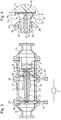
- ✔ La
figure 1 est une vue schématique de profil d'un mode de réalisation préférentiel d'un réacteur à plasma tournant selon l'invention. - ✔ la
figure 2 est une vue schématique de face du réacteur à plasma tournant de lafigure 1 . - ✔ la
figure 3 est une coupe longitudinale selon un plan B'B, tel que repéré sur lafigure 2 , du réacteur à plasma de lafigure 1 . - ✔ La
figure 4 est un agrandissement d'une portion du réacteur à plasma de lafigure 3 , - ✔ la
figure 5 est une vue schématique de face d'un disque de contrôle selon l'invention, - ✔ la
figure 6 est une coupe longitudinale du disque de contrôle de lafigure 5 .
- ✔ The
figure 1 is a schematic side view of a preferred embodiment of a rotating plasma reactor according to the invention. - ✔ the
figure 2 is a schematic front view of the rotating plasma reactor of thefigure 1 . - ✔ the
figure 3 is a longitudinal section along a plane B'B, as marked on thefigure 2 , the plasma reactor of thefigure 1 . - ✔ The
figure 4 is an enlargement of a portion of the plasma reactor of thefigure 3 , - ✔ the
figure 5 is a schematic front view of a control disk according to the invention, - ✔ the
figure 6 is a longitudinal section of the control disk of thefigure 5 .
Conformément à la version préférée de l'invention, le réacteur illustré sur les
L'enceinte 10 comprend une portion d'enceinte 11 délimitant une chambre de réaction 19, une portion d'enceinte 12 formant rallonge, un embout d'entrée 13 formé par un raccord normalisé de type DN 16, par lequel le fluide (réactifs) est introduit axialement dans le réacteur, et un embout de sortie 14 formé par un raccord normalisé de type DN 16, par lequel le fluide (produits de réaction et éventuels réactifs n'ayant pas réagi) sort axialement du réacteur. L'enceinte 10 est symétrique de révolution autour d'un axe central 1. Les portions d'enceinte 11 et 12 sont essentiellement cylindriques -de section circulaire- à l'exception de leurs extrémités axiales qui sont en forme de collerette. Ces portions d'enceintes 11 et 12 sont en un matériau structurant, de préférence transparent et léger, tel que le polyméthacrylate de méthyle connu sous le nom commercial Plexiglas®. L'utilisation de raccords normalisés pour la réalisation des embouts d'entrée 13 et de sortie 14 facilite l'intégration du réacteur selon l'invention dans un système et facilite également le raccordement en série de plusieurs réacteurs selon l'invention.The
Dans toute la description, les termes « amont » et « aval » font référence à la direction axiale définie par l'axe central 1 du réacteur et au sens de circulation globale du fluide 5. Sur les
La bougie d'allumage 2 est une bougie d'allumage traditionnelle pour véhicule automobile à essence, dans laquelle on peut reconnaître une électrode centrale 21 à tige (dite tige centrale 21 par la suite), un isolateur 23 en céramique et un corps de bougie 22 métallique. De façon usuelle, la tige centrale 21 présente une extrémité aval 25 qui s'étend axialement en saillie de l'isolateur 23, et une extrémité opposée qui est elle aussi « dénudée » (c'est-à-dire dépourvue d'isolateur à sa périphérie) de façon à offrir une zone de connexion 24.
En raison de la présence d'un épaulement dans l'isolateur 23, un espace cylindrique 28, appelé ici espace cylindrique de circulation, apparaît entre l'isolateur 23 et le corps de bougie 22 à proximité de l'extrémité aval 25 de la tige centrale 21.Due to the presence of a shoulder in the
La tige centrale 21 de la bougie d'allumage 2 fait partie d'une première électrode du réacteur à plasma, tandis que le corps de bougie 22 fait partie d'une seconde électrode du réacteur à plasma.The
La bougie d'allumage 2 est agencée à l'intérieur de l'enceinte 10 de façon à ce que son axe central coïncide avec l'axe central 1 du réacteur et à ce que l'extrémité aval 25 de son électrode centrale 21 soit située dans la chambre de réaction 19 du réacteur.The
La bougie d'allumage 2 traditionnelle a subi deux modifications :
- ✔ des trous de
circulation 26 d'axes radiaux et débouchant dans l'espace cylindrique decirculation 28 ont été ménagés dans le corps de bougie 22 ; - ✔ l'électrode de masse qui prolonge usuellement le corps de bougie en formant une patte saillante en regard de l'extrémité aval 25 de l'électrode centrale a été sectionnée (elle n'apparaît donc pas sur les figures) de sorte que le corps de bougie 22 présente une face
extrême 27, appelée ici extrémité de décharge, qui est plane (elle s'étend dans un plan transversal orthogonal à l'axe central 1).
- ✔ circulation holes 26 of radial axes and opening into the
cylindrical circulation space 28 have been formed in thecandle body 22; - ✔ the ground electrode which usually extends the candle body by forming a protruding tab facing the
downstream end 25 of the central electrode has been cut off (so it does not appear in the figures) so that thebody spark plug 22 has anend face 27, here called discharge end, which is flat (it extends in a transverse plane orthogonal to the central axis 1).
L'aimant permanent 3 est un aimant en forme de disque dont l'axe coïncide avec l'axe central 1 du réacteur. Il s'agit avantageusement d'un aimant en néodyme.The
Le disque de contrôle 4 est en un matériau conducteur d'électricité, par exemple en cuivre. Il présente une face avant 40 décrite plus en détail plus loin, et une face arrière qui est accolée à l'aimant permanent 3 et est de même diamètre que ce dernier. À l'instar de l'aimant permanent 3, le disque de contrôle 4 est centré sur l'axe central 1 du réacteur.The
En son centre, la face avant 40 du disque de contrôle 4 présente un ergot 41 qui la relie à l'extrémité aval 25 de la tige centrale 21 de la bougie d'allumage. Le disque de contrôle 4 prolonge ainsi la tige centrale 21 et fait partie de la première électrode du réacteur.At its center, the
La face avant 40 du disque de contrôle présente des zones en creux concentriques, obtenues par gravure par exemple : une première zone centrale 42 à fond plat et angles adoucis, trois rainures circulaires 43 et un chanfrein externe 44. Ces zones gravées forment quatre nervures circulaires concentriques 45 définissant quatre cercles de départ d'arc électriques.The
En fonctionnement, des arcs électriques sont produits sous l'effet de la différence de potentiels entre les deux électrodes, entre l'extrémité de décharge 27 du corps de bougie (seconde électrode du réacteur) et la face avant 40 du disque de contrôle (première électrode du réacteur). Ces arcs électriques forment un cône de réaction 6 générant un rideau tubulaire de plasma. La référence 6 désigne aussi bien le cône de réaction (en tant que forme géométrique sur laquelle s'inscrivent les arcs électriques générés) que le rideau tubulaire de plasma (résultant de l'effet des arcs électriques sur le fluide en circulation).In operation, electric arcs are produced under the effect of the potential difference between the two electrodes, between the discharge end 27 of the spark plug body (second electrode of the reactor) and the
La forme circulaire des nervures 45 prévues sur la face avant 40 du disque de contrôle est avantageuse compte tenu de la symétrie de révolution de l'aimant permanent 3 et du champ magnétique qu'il génère. Cette forme circulaire permet d'obtenir un arc électrique tournant se déplaçant à vitesse constante. Elle limite les risques d'interruption du rideau tubulaire de plasma 6 obtenu.The circular shape of the
La présence, sur la face avant 40 du disque 4 de plusieurs nervures circulaires 45 de diamètres différents permet de disposer de plusieurs cercles de départ d'arc électrique situés à différentes distances de l'autre électrode (extrémité de décharge 27 du corps de bougie). Les chances de déclencher aisément un arc électrique et d'entretenir un rideau de plasma tournant sont ainsi multipliées et un même disque peut, de surcroît, être utilisé pour différentes applications. Selon l'invention, il suffit donc que la face avant du disque de contrôle présente au moins une nervure circulaire.The presence on the
En l'exemple non limitatif illustré, la distance selon la direction axiale entre l'extrémité de décharge 27 du corps de bougie et la face avant 40 du disque de contrôle et de 5,2 mm. La distance entre un point de l'arête circulaire externe de l'extrémité de décharge 27 du corps de bougie et un point du disque de contrôle 4 situé dans le même plan longitudinal et sur la nervure 45 de plus petit diamètre est de 5,5 mm. Le diamètre du disque de contrôle 4 et de l'aimant permanent 3 est de 22 mm. La profondeur des zone gravée 42 et rainures 43 est de 0,5 mm. La pente des nervures 45 est de 45°.In the nonlimiting example illustrated, the distance in the axial direction between the discharge end 27 of the candle body and the
Parmi les paramètres les plus influents sur le fonctionnement du réacteur, on peut citer : le rayon de la nervure du disque de contrôle 4, la distance entre cette nervure et l'extrémité de décharge 27 du corps de bougie, les caractéristiques de l'aimant permanent 3, le débit et la pression des réactifs en présence, la tension (et donc de la différence de potentiels entre les deux électrodes du réacteur) et la fréquence de la source électrique 7. Ces divers paramètres sont à optimiser en fonction de l'application concernée. Les dimensions précédemment indiquées à titre d'exemples peuvent ne pas être optimales selon l'application envisagée.Among the most influential parameters on the operation of the reactor, mention may be made of: the radius of the rib of the
Le réacteur comprend de plus une rondelle plate 29, reliée en son centre à la zone de connexion 24 de la tige centrale 21 et fixée, d'un côté, à une extrémité aval de l'embout d'entrée 13 et, de l'autre côté, à une extrémité amont de la portion d'enceinte 12 formant rallonge. Une tige filetée 31 est vissée dans un alésage radial de cette rondelle plate 29. Cette tige filetée 31 sert de fiche pour la connexion électrique de la première électrode du réacteur à la source de tension alternative 7. La rondelle plate 29 est percée d'une pluralité d'ouvertures 30 selon la direction axiale, qui permettent le passage du fluide depuis l'embout d'entrée 13 vers la rallonge 12.The reactor further comprises a
Le réacteur comprend de plus une rondelle conique 32 dont le sommet percé du cône enserre le corps de bougie 22 en aval des trous de circulation 26, et dont la base du cône est prolongée par une collerette fixée, d'un côté, à une extrémité aval de la portion d'enceinte 12 formant rallonge et, de l'autre côté, à une extrémité amont de la portion d'enceinte 11 délimitant la chambre de réaction. Un alésage radial est ménagé dans cette collerette pour la réception d'une tige filetée 33 servant de fiche pour la connexion électrique de la seconde électrode du réacteur à la source de tension alternative. La forme conique de la rondelle 32 contraint le fluide arrivant axialement depuis l'embout d'entrée 13 et la rallonge 12 vers les trous de circulation 26. La façon (moyens utilisés, tels que pompe, débit choisi, etc.) dont la circulation du fluide est assurée dans le système dans lequel le réacteur est intégré dépend de l'application considérée et est indifférente à la présente invention. Le fluide peut par exemple être introduit dans le réacteur à l'aide d'une pompe (non représentée) agencée en amont ou en en aval de celui-ci. A l'intérieur du réacteur, le trajet de circulation du fluide peut être observé à la
Comme on peut le constater, l'ensemble du réacteur peut être fabriqué à partir d'éléments simples et courants, disponibles dans le commerce à des prix abordables voir faibles. L'ensemble obtenu est très compact : l'exemple illustré (hors source d'alimentation 7) a diamètre externe maximal de 55 mm (diamètre externe de la rondelle plate 29 et de la collerette de la rondelle conique 32) et une longueur de 153 mm. Le réacteur fournit un très bon rendement qui peut facilement être optimisé notamment en adaptant la distance entre l'extrémité de décharge 27 de la seconde électrode et le disque de contrôle 4 ainsi que le motif en relief prévu sur la face avant 40 de ce dernier, en fonction notamment de la réaction souhaitée et du débit du fluide.As can be seen, the entire reactor can be made from simple and common items, commercially available at affordable or low prices. The set obtained is very compact: the illustrated example (excluding power source 7) has a maximum outer diameter of 55 mm (external diameter of the
L'invention peut faire l'objet de nombreuses variantes par rapport aux modes de réalisation décrits ci-dessus et illustrés, par exemple dans le choix des matériaux utilisés, dans les dimensions, etc., dès lors que celles-ci restent dans le cadre défini par les revendications annexées.The invention can be the subject of numerous variants with respect to the embodiments described above and illustrated, for example in the choice of materials used, in dimensions, etc., as long as they remain in the frame. defined by the appended claims.
Claims (11)
- A plasma reactor for forming a plasma in a flowing fluid, the reactor comprising:✔ a first (21, 4, 29, 31) and a second electrode (22, 32, 33) connected to a source of alternating voltage (7), for the creation of electric arcs between said first and second electrodes for the purposes of generating a plasma in the flowing fluid,✔ a portion of vessel (11) delimiting a reaction chamber (19) within which the plasma is generated,✔ the first electrode comprises a central rod (21) arranged on a central axis (1) of the reactor, which rod is enveloped with an insulator (23) except for a downstream end (25), which projects from the insulator, and a connection region (24),✔ the second electrode comprises a tubular body (22) surrounding the insulator (23) and having a discharge end (27) situated in the reaction chamber (19),✔ the reactor comprises a control disk (4), which is a conductor and which has a front face (40) linked to the downstream end (25) of the central rod of the first electrode,✔ the reactor comprises a permanent magnet (3) juxtaposed against a back face of the control disk (4),✔ one or more grooves (42, 43, 44) or ribs (45) are formed on the front face (40) of the control disk according to a pattern in relief defining successive electric arc starting points (45) distributed around the central axis (1) of the reactor so as to generate electric arcs which are situated on a reaction cone (6) and appear to turn around the central axis (1),✔ the reactor has a cylindrical space (28) for flow between the tubular body (22) of the second electrode and the insulator (23), into which cylindrical space (28) the fluid is introduced and from which it leaves again within the reaction cone (6).
- A plasma reactor according to claim 1, characterized in that the pattern in relief on the front face (40) of the control disk comprises at least one circular rib (45).
- A plasma reactor according to claim 1 or 2, characterized in that the discharge end (27) of the tubular body of the second electrode is planar.
- A plasma reactor according to one of the preceding claims, characterized in that the tubular body (22) of the second electrode is perforated with flow holes (26) open to the cylindrical flow space (28).
- A plasma reactor according to one of the preceding claims, characterized in that the control disk (4) and the permanent magnet (3) each have a greater diameter than an outside diameter of the discharge end (27) of the tubular body of the second electrode.
- A plasma reactor according to one of the preceding claims, characterized in that the portion of vessel (11) delimiting the reaction chamber is of a transparent material.
- A plasma reactor according to one of the preceding claims, characterized in that the reactor comprises a portion of vessel (12) forming an extension, which extends axially and upstream the portion of vessel (11) delimiting the reaction chamber.
- A plasma reactor according to one of the preceding claims, characterized in that it comprises:✔ a flat conducting washer (29) attached to the connection region (24) of the central rod of the first electrode, and✔ a first jack (30) in contact with said flat conducting washer (29) for the connection of the first electrode to the source of alternating voltage (7), the flat conducting washer (29) being furthermore configured to enable its fastening to the portion of vessel (12) forming an extension.✔ the flat conducting washer (29) being axially perforated with openings (30) for the passage of the fluid.
- A plasma reactor according to one of the preceding claims, characterized in that it comprises:✔ a conical conducting washer (32) having an apex joined to the tubular body (22) of the second electrode downstream of the flow holes (26) of said body and a base situated upstream of said flow holes, which base is extended by a connection rim configured to enable its fastening to the portion of vessel (11) delimiting the reaction chamber, and✔ a second jack (33) in contact with the connection rim of the conical conducting washer (32) for the connection of the second electrode to the source of alternating voltage (7).
- A plasma reactor according to claim 7, characterized in that it comprises:✔ an inlet end formation (13) formed by a standard connector, arranged upstream of the portion of vessel (12) forming an extension and fastened thereto,✔ an outlet end formation (14) formed by a standard connector, arranged downstream of the portion of vessel (11) delimiting the reaction chamber and fastened thereto.
- A plasma reactor according to one of the preceding claims, characterized in that it comprises a spark plug (2), comprising a central rod electrode and a plug body lacking any projecting ground electrode, the central rod electrode of the spark plug forming the central rod (21) of the first electrode of the reactor, the plug body of the spark plug forming the tubular body (22) of the second electrode of the reactor, the insulator of the spark plug corresponding to the insulator (23) of the reactor.
Applications Claiming Priority (1)
| Application Number | Priority Date | Filing Date | Title |
|---|---|---|---|
| FR1555106A FR3037209B1 (en) | 2015-06-04 | 2015-06-04 | COLD PLASMA ROTATING AND FLOW FORCING REACTOR |
Publications (2)
| Publication Number | Publication Date |
|---|---|
| EP3102008A1 EP3102008A1 (en) | 2016-12-07 |
| EP3102008B1 true EP3102008B1 (en) | 2017-11-22 |
Family
ID=54066029
Family Applications (1)
| Application Number | Title | Priority Date | Filing Date |
|---|---|---|---|
| EP16171896.0A Active EP3102008B1 (en) | 2015-06-04 | 2016-05-30 | Rotary, forced-flow cold plasma reactor |
Country Status (4)
| Country | Link |
|---|---|
| US (1) | US9744517B2 (en) |
| EP (1) | EP3102008B1 (en) |
| ES (1) | ES2659070T3 (en) |
| FR (1) | FR3037209B1 (en) |
Family Cites Families (5)
| Publication number | Priority date | Publication date | Assignee | Title |
|---|---|---|---|---|
| US3378713A (en) * | 1965-06-08 | 1968-04-16 | Westinghouse Electric Corp | High-intensity radiation source comprising rotating arc |
| CA1323670C (en) * | 1988-05-17 | 1993-10-26 | Subramania Ramakrishnan | Electric arc reactor |
| WO2000001047A1 (en) * | 1998-06-29 | 2000-01-06 | Witherspoon Chris W | Corona wind spark plug |
| WO2014130697A1 (en) * | 2013-02-20 | 2014-08-28 | University Of Southern California | Transient plasma electrode for radical generation |
| JP6761342B2 (en) * | 2013-04-10 | 2020-09-23 | アムリカ メルサンタイル プライベート リミテッド | Cold plasma generators and methods for producing related chemicals |
-
2015
- 2015-06-04 FR FR1555106A patent/FR3037209B1/en not_active Expired - Fee Related
-
2016
- 2016-05-30 EP EP16171896.0A patent/EP3102008B1/en active Active
- 2016-05-30 ES ES16171896.0T patent/ES2659070T3/en active Active
- 2016-06-02 US US15/171,576 patent/US9744517B2/en active Active
Non-Patent Citations (1)
| Title |
|---|
| None * |
Also Published As
| Publication number | Publication date |
|---|---|
| ES2659070T3 (en) | 2018-03-13 |
| FR3037209A1 (en) | 2016-12-09 |
| US9744517B2 (en) | 2017-08-29 |
| FR3037209B1 (en) | 2017-07-21 |
| EP3102008A1 (en) | 2016-12-07 |
| US20160354755A1 (en) | 2016-12-08 |
Similar Documents
| Publication | Publication Date | Title |
|---|---|---|
| EP3089836B1 (en) | Method for fixing a metal ring in a frame and induction coil obtained by said method | |
| FR2932318A1 (en) | BRUSH HOLDER TIP AND ITS APPLICATION TO THE PRODUCTION OF A STARTER FOR A MOTOR VEHICLE | |
| EP3102008B1 (en) | Rotary, forced-flow cold plasma reactor | |
| FR2656163A1 (en) | MAIN EXCITATION COIL CONNECTOR ALLOWING A HIGH NUMBER OF STARTING / STOPPING CYCLES. | |
| FR2947416A1 (en) | DEVICE FOR TRANSMITTING A PLASMA JET FROM ATMOSPHERIC AIR AT TEMPERATURE AND AMBIENT PRESSURE AND USE OF SUCH A DEVICE | |
| FR3058661B1 (en) | MAGNETIC IMPULSE WELDING METHOD OF A STACK OF SHEETS | |
| FR2863817A1 (en) | TUYERE WITH DEFLECTOR FOR PLASMA ARC TORCH | |
| EP0185226B1 (en) | Gas flow laser and functioning method of such a laser | |
| EP0750449A1 (en) | Plasma torch head and plasma torch equipped with it | |
| FR2987288A1 (en) | HEAD OF AN ELECTROHYDRAULIC WIRE DISCHARGE DEVICE | |
| EP1152445B1 (en) | Vacuum tube for an electrical protection apparatus such as a switch or a circuit breaker | |
| EP3560299B1 (en) | Dbd plasma reactor | |
| FR2887696A1 (en) | IGNITION CANDLE FOR INTERNAL COMBUSTION ENGINE | |
| EP3046665A1 (en) | Fluidized bed catalytic reactor comprising a surface plasma generator | |
| WO2015055626A1 (en) | Method for crimping using magnetic pulses | |
| EP3384566B1 (en) | Ion-generating device | |
| WO2016066939A1 (en) | Device for converting mechanical energy from sound waves into electricity | |
| FR2895291A1 (en) | Production of a support component comprising a plate and a perpendicular pin linked by a simple mechanical method, notably for the mass produced support components of frames | |
| FR2508268A1 (en) | ARC HEATER HAVING AN IMPROVED SELF-PRIMING CHARACTERISTIC FOR A GAS FLOWING AT A HIGH FLOW | |
| FR2632785A1 (en) | SEMI-SUPERFICIAL DISCHARGE IGNITION CANDLE FOR INTERNAL COMBUSTION ENGINE, AND PROCESS FOR PRODUCING THE MASS ELECTRODES OF SAID CANDLE | |
| FR2750286A1 (en) | PLASMA TORCH HEAD | |
| FR2627018A1 (en) | ELECTRICAL CONNECTION TIP | |
| WO2023143816A1 (en) | Downstream nozzle for a plasma cutting torch | |
| WO2023143817A1 (en) | Improved electrode for a plasma cutting torch | |
| FR2731833A1 (en) | Induction coil for use in magneto-forming equipment |
Legal Events
| Date | Code | Title | Description |
|---|---|---|---|
| PUAI | Public reference made under article 153(3) epc to a published international application that has entered the european phase |
Free format text: ORIGINAL CODE: 0009012 |
|
| STAA | Information on the status of an ep patent application or granted ep patent |
Free format text: STATUS: THE APPLICATION HAS BEEN PUBLISHED |
|
| AK | Designated contracting states |
Kind code of ref document: A1 Designated state(s): AL AT BE BG CH CY CZ DE DK EE ES FI FR GB GR HR HU IE IS IT LI LT LU LV MC MK MT NL NO PL PT RO RS SE SI SK SM TR |
|
| AX | Request for extension of the european patent |
Extension state: BA ME |
|
| STAA | Information on the status of an ep patent application or granted ep patent |
Free format text: STATUS: REQUEST FOR EXAMINATION WAS MADE |
|
| 17P | Request for examination filed |
Effective date: 20170510 |
|
| RBV | Designated contracting states (corrected) |
Designated state(s): AL AT BE BG CH CY CZ DE DK EE ES FI FR GB GR HR HU IE IS IT LI LT LU LV MC MK MT NL NO PL PT RO RS SE SI SK SM TR |
|
| GRAP | Despatch of communication of intention to grant a patent |
Free format text: ORIGINAL CODE: EPIDOSNIGR1 |
|
| STAA | Information on the status of an ep patent application or granted ep patent |
Free format text: STATUS: GRANT OF PATENT IS INTENDED |
|
| INTG | Intention to grant announced |
Effective date: 20170623 |
|
| GRAS | Grant fee paid |
Free format text: ORIGINAL CODE: EPIDOSNIGR3 |
|
| GRAA | (expected) grant |
Free format text: ORIGINAL CODE: 0009210 |
|
| STAA | Information on the status of an ep patent application or granted ep patent |
Free format text: STATUS: THE PATENT HAS BEEN GRANTED |
|
| AK | Designated contracting states |
Kind code of ref document: B1 Designated state(s): AL AT BE BG CH CY CZ DE DK EE ES FI FR GB GR HR HU IE IS IT LI LT LU LV MC MK MT NL NO PL PT RO RS SE SI SK SM TR |
|
| REG | Reference to a national code |
Ref country code: GB Ref legal event code: FG4D Free format text: NOT ENGLISH |
|
| REG | Reference to a national code |
Ref country code: CH Ref legal event code: EP |
|
| REG | Reference to a national code |
Ref country code: IE Ref legal event code: FG4D Free format text: LANGUAGE OF EP DOCUMENT: FRENCH |
|
| REG | Reference to a national code |
Ref country code: AT Ref legal event code: REF Ref document number: 949525 Country of ref document: AT Kind code of ref document: T Effective date: 20171215 |
|
| REG | Reference to a national code |
Ref country code: DE Ref legal event code: R096 Ref document number: 602016000875 Country of ref document: DE |
|
| REG | Reference to a national code |
Ref country code: ES Ref legal event code: FG2A Ref document number: 2659070 Country of ref document: ES Kind code of ref document: T3 Effective date: 20180313 |
|
| REG | Reference to a national code |
Ref country code: NL Ref legal event code: MP Effective date: 20171122 |
|
| REG | Reference to a national code |
Ref country code: LT Ref legal event code: MG4D |
|
| REG | Reference to a national code |
Ref country code: AT Ref legal event code: MK05 Ref document number: 949525 Country of ref document: AT Kind code of ref document: T Effective date: 20171122 |
|
| PG25 | Lapsed in a contracting state [announced via postgrant information from national office to epo] |
Ref country code: NL Free format text: LAPSE BECAUSE OF FAILURE TO SUBMIT A TRANSLATION OF THE DESCRIPTION OR TO PAY THE FEE WITHIN THE PRESCRIBED TIME-LIMIT Effective date: 20171122 Ref country code: FI Free format text: LAPSE BECAUSE OF FAILURE TO SUBMIT A TRANSLATION OF THE DESCRIPTION OR TO PAY THE FEE WITHIN THE PRESCRIBED TIME-LIMIT Effective date: 20171122 Ref country code: NO Free format text: LAPSE BECAUSE OF FAILURE TO SUBMIT A TRANSLATION OF THE DESCRIPTION OR TO PAY THE FEE WITHIN THE PRESCRIBED TIME-LIMIT Effective date: 20180222 Ref country code: LT Free format text: LAPSE BECAUSE OF FAILURE TO SUBMIT A TRANSLATION OF THE DESCRIPTION OR TO PAY THE FEE WITHIN THE PRESCRIBED TIME-LIMIT Effective date: 20171122 Ref country code: SE Free format text: LAPSE BECAUSE OF FAILURE TO SUBMIT A TRANSLATION OF THE DESCRIPTION OR TO PAY THE FEE WITHIN THE PRESCRIBED TIME-LIMIT Effective date: 20171122 |
|
| REG | Reference to a national code |
Ref country code: FR Ref legal event code: PLFP Year of fee payment: 3 |
|
| PG25 | Lapsed in a contracting state [announced via postgrant information from national office to epo] |
Ref country code: LV Free format text: LAPSE BECAUSE OF FAILURE TO SUBMIT A TRANSLATION OF THE DESCRIPTION OR TO PAY THE FEE WITHIN THE PRESCRIBED TIME-LIMIT Effective date: 20171122 Ref country code: AT Free format text: LAPSE BECAUSE OF FAILURE TO SUBMIT A TRANSLATION OF THE DESCRIPTION OR TO PAY THE FEE WITHIN THE PRESCRIBED TIME-LIMIT Effective date: 20171122 Ref country code: RS Free format text: LAPSE BECAUSE OF FAILURE TO SUBMIT A TRANSLATION OF THE DESCRIPTION OR TO PAY THE FEE WITHIN THE PRESCRIBED TIME-LIMIT Effective date: 20171122 Ref country code: GR Free format text: LAPSE BECAUSE OF FAILURE TO SUBMIT A TRANSLATION OF THE DESCRIPTION OR TO PAY THE FEE WITHIN THE PRESCRIBED TIME-LIMIT Effective date: 20180223 Ref country code: HR Free format text: LAPSE BECAUSE OF FAILURE TO SUBMIT A TRANSLATION OF THE DESCRIPTION OR TO PAY THE FEE WITHIN THE PRESCRIBED TIME-LIMIT Effective date: 20171122 Ref country code: BG Free format text: LAPSE BECAUSE OF FAILURE TO SUBMIT A TRANSLATION OF THE DESCRIPTION OR TO PAY THE FEE WITHIN THE PRESCRIBED TIME-LIMIT Effective date: 20180222 |
|
| PG25 | Lapsed in a contracting state [announced via postgrant information from national office to epo] |
Ref country code: CZ Free format text: LAPSE BECAUSE OF FAILURE TO SUBMIT A TRANSLATION OF THE DESCRIPTION OR TO PAY THE FEE WITHIN THE PRESCRIBED TIME-LIMIT Effective date: 20171122 Ref country code: SK Free format text: LAPSE BECAUSE OF FAILURE TO SUBMIT A TRANSLATION OF THE DESCRIPTION OR TO PAY THE FEE WITHIN THE PRESCRIBED TIME-LIMIT Effective date: 20171122 Ref country code: EE Free format text: LAPSE BECAUSE OF FAILURE TO SUBMIT A TRANSLATION OF THE DESCRIPTION OR TO PAY THE FEE WITHIN THE PRESCRIBED TIME-LIMIT Effective date: 20171122 Ref country code: CY Free format text: LAPSE BECAUSE OF FAILURE TO SUBMIT A TRANSLATION OF THE DESCRIPTION OR TO PAY THE FEE WITHIN THE PRESCRIBED TIME-LIMIT Effective date: 20171122 Ref country code: DK Free format text: LAPSE BECAUSE OF FAILURE TO SUBMIT A TRANSLATION OF THE DESCRIPTION OR TO PAY THE FEE WITHIN THE PRESCRIBED TIME-LIMIT Effective date: 20171122 |
|
| REG | Reference to a national code |
Ref country code: DE Ref legal event code: R097 Ref document number: 602016000875 Country of ref document: DE |
|
| PG25 | Lapsed in a contracting state [announced via postgrant information from national office to epo] |
Ref country code: SM Free format text: LAPSE BECAUSE OF FAILURE TO SUBMIT A TRANSLATION OF THE DESCRIPTION OR TO PAY THE FEE WITHIN THE PRESCRIBED TIME-LIMIT Effective date: 20171122 Ref country code: PL Free format text: LAPSE BECAUSE OF FAILURE TO SUBMIT A TRANSLATION OF THE DESCRIPTION OR TO PAY THE FEE WITHIN THE PRESCRIBED TIME-LIMIT Effective date: 20171122 |
|
| PG25 | Lapsed in a contracting state [announced via postgrant information from national office to epo] |
Ref country code: MT Free format text: LAPSE BECAUSE OF FAILURE TO SUBMIT A TRANSLATION OF THE DESCRIPTION OR TO PAY THE FEE WITHIN THE PRESCRIBED TIME-LIMIT Effective date: 20171122 |
|
| PLBE | No opposition filed within time limit |
Free format text: ORIGINAL CODE: 0009261 |
|
| STAA | Information on the status of an ep patent application or granted ep patent |
Free format text: STATUS: NO OPPOSITION FILED WITHIN TIME LIMIT |
|
| 26N | No opposition filed |
Effective date: 20180823 |
|
| PG25 | Lapsed in a contracting state [announced via postgrant information from national office to epo] |
Ref country code: SI Free format text: LAPSE BECAUSE OF FAILURE TO SUBMIT A TRANSLATION OF THE DESCRIPTION OR TO PAY THE FEE WITHIN THE PRESCRIBED TIME-LIMIT Effective date: 20171122 |
|
| REG | Reference to a national code |
Ref country code: BE Ref legal event code: MM Effective date: 20180531 |
|
| PG25 | Lapsed in a contracting state [announced via postgrant information from national office to epo] |
Ref country code: MC Free format text: LAPSE BECAUSE OF FAILURE TO SUBMIT A TRANSLATION OF THE DESCRIPTION OR TO PAY THE FEE WITHIN THE PRESCRIBED TIME-LIMIT Effective date: 20171122 |
|
| REG | Reference to a national code |
Ref country code: IE Ref legal event code: MM4A |
|
| PG25 | Lapsed in a contracting state [announced via postgrant information from national office to epo] |
Ref country code: LU Free format text: LAPSE BECAUSE OF NON-PAYMENT OF DUE FEES Effective date: 20180530 |
|
| PG25 | Lapsed in a contracting state [announced via postgrant information from national office to epo] |
Ref country code: IE Free format text: LAPSE BECAUSE OF NON-PAYMENT OF DUE FEES Effective date: 20180530 |
|
| PG25 | Lapsed in a contracting state [announced via postgrant information from national office to epo] |
Ref country code: BE Free format text: LAPSE BECAUSE OF NON-PAYMENT OF DUE FEES Effective date: 20180531 |
|
| REG | Reference to a national code |
Ref country code: CH Ref legal event code: PL |
|
| PG25 | Lapsed in a contracting state [announced via postgrant information from national office to epo] |
Ref country code: LI Free format text: LAPSE BECAUSE OF NON-PAYMENT OF DUE FEES Effective date: 20190531 Ref country code: CH Free format text: LAPSE BECAUSE OF NON-PAYMENT OF DUE FEES Effective date: 20190531 |
|
| PG25 | Lapsed in a contracting state [announced via postgrant information from national office to epo] |
Ref country code: TR Free format text: LAPSE BECAUSE OF FAILURE TO SUBMIT A TRANSLATION OF THE DESCRIPTION OR TO PAY THE FEE WITHIN THE PRESCRIBED TIME-LIMIT Effective date: 20171122 |
|
| PG25 | Lapsed in a contracting state [announced via postgrant information from national office to epo] |
Ref country code: PT Free format text: LAPSE BECAUSE OF FAILURE TO SUBMIT A TRANSLATION OF THE DESCRIPTION OR TO PAY THE FEE WITHIN THE PRESCRIBED TIME-LIMIT Effective date: 20171122 |
|
| PG25 | Lapsed in a contracting state [announced via postgrant information from national office to epo] |
Ref country code: HU Free format text: LAPSE BECAUSE OF FAILURE TO SUBMIT A TRANSLATION OF THE DESCRIPTION OR TO PAY THE FEE WITHIN THE PRESCRIBED TIME-LIMIT; INVALID AB INITIO Effective date: 20160530 Ref country code: MK Free format text: LAPSE BECAUSE OF NON-PAYMENT OF DUE FEES Effective date: 20171122 Ref country code: RO Free format text: LAPSE BECAUSE OF FAILURE TO SUBMIT A TRANSLATION OF THE DESCRIPTION OR TO PAY THE FEE WITHIN THE PRESCRIBED TIME-LIMIT Effective date: 20171122 |
|
| PG25 | Lapsed in a contracting state [announced via postgrant information from national office to epo] |
Ref country code: AL Free format text: LAPSE BECAUSE OF FAILURE TO SUBMIT A TRANSLATION OF THE DESCRIPTION OR TO PAY THE FEE WITHIN THE PRESCRIBED TIME-LIMIT Effective date: 20171122 Ref country code: IS Free format text: LAPSE BECAUSE OF FAILURE TO SUBMIT A TRANSLATION OF THE DESCRIPTION OR TO PAY THE FEE WITHIN THE PRESCRIBED TIME-LIMIT Effective date: 20180322 |
|
| P01 | Opt-out of the competence of the unified patent court (upc) registered |
Effective date: 20230517 |
|
| PGFP | Annual fee paid to national office [announced via postgrant information from national office to epo] |
Ref country code: IT Payment date: 20230531 Year of fee payment: 8 Ref country code: FR Payment date: 20230519 Year of fee payment: 8 Ref country code: ES Payment date: 20230621 Year of fee payment: 8 Ref country code: DE Payment date: 20230519 Year of fee payment: 8 |
|
| PGFP | Annual fee paid to national office [announced via postgrant information from national office to epo] |
Ref country code: GB Payment date: 20230523 Year of fee payment: 8 |