EP3101418B1 - Gas analyzing apparatus comprising a temperature controlling system for the capillary sampling device - Google Patents
Gas analyzing apparatus comprising a temperature controlling system for the capillary sampling device Download PDFInfo
- Publication number
- EP3101418B1 EP3101418B1 EP15875162.8A EP15875162A EP3101418B1 EP 3101418 B1 EP3101418 B1 EP 3101418B1 EP 15875162 A EP15875162 A EP 15875162A EP 3101418 B1 EP3101418 B1 EP 3101418B1
- Authority
- EP
- European Patent Office
- Prior art keywords
- ion mobility
- spectrum analysis
- analysis device
- analyzing apparatus
- capillary column
- Prior art date
- Legal status (The legal status is an assumption and is not a legal conclusion. Google has not performed a legal analysis and makes no representation as to the accuracy of the status listed.)
- Not-in-force
Links
Images
Classifications
-
- G—PHYSICS
- G01—MEASURING; TESTING
- G01N—INVESTIGATING OR ANALYSING MATERIALS BY DETERMINING THEIR CHEMICAL OR PHYSICAL PROPERTIES
- G01N27/00—Investigating or analysing materials by the use of electric, electrochemical, or magnetic means
- G01N27/62—Investigating or analysing materials by the use of electric, electrochemical, or magnetic means by investigating the ionisation of gases, e.g. aerosols; by investigating electric discharges, e.g. emission of cathode
- G01N27/622—Ion mobility spectrometry
-
- G—PHYSICS
- G01—MEASURING; TESTING
- G01N—INVESTIGATING OR ANALYSING MATERIALS BY DETERMINING THEIR CHEMICAL OR PHYSICAL PROPERTIES
- G01N27/00—Investigating or analysing materials by the use of electric, electrochemical, or magnetic means
- G01N27/62—Investigating or analysing materials by the use of electric, electrochemical, or magnetic means by investigating the ionisation of gases, e.g. aerosols; by investigating electric discharges, e.g. emission of cathode
- G01N27/64—Investigating or analysing materials by the use of electric, electrochemical, or magnetic means by investigating the ionisation of gases, e.g. aerosols; by investigating electric discharges, e.g. emission of cathode using wave or particle radiation to ionise a gas, e.g. in an ionisation chamber
-
- G—PHYSICS
- G01—MEASURING; TESTING
- G01N—INVESTIGATING OR ANALYSING MATERIALS BY DETERMINING THEIR CHEMICAL OR PHYSICAL PROPERTIES
- G01N30/00—Investigating or analysing materials by separation into components using adsorption, absorption or similar phenomena or using ion-exchange, e.g. chromatography or field flow fractionation
- G01N30/02—Column chromatography
- G01N30/26—Conditioning of the fluid carrier; Flow patterns
- G01N30/28—Control of physical parameters of the fluid carrier
- G01N30/30—Control of physical parameters of the fluid carrier of temperature
-
- G—PHYSICS
- G01—MEASURING; TESTING
- G01N—INVESTIGATING OR ANALYSING MATERIALS BY DETERMINING THEIR CHEMICAL OR PHYSICAL PROPERTIES
- G01N30/00—Investigating or analysing materials by separation into components using adsorption, absorption or similar phenomena or using ion-exchange, e.g. chromatography or field flow fractionation
- G01N30/02—Column chromatography
- G01N30/26—Conditioning of the fluid carrier; Flow patterns
- G01N30/38—Flow patterns
- G01N30/46—Flow patterns using more than one column
- G01N30/466—Flow patterns using more than one column with separation columns in parallel
-
- G—PHYSICS
- G01—MEASURING; TESTING
- G01N—INVESTIGATING OR ANALYSING MATERIALS BY DETERMINING THEIR CHEMICAL OR PHYSICAL PROPERTIES
- G01N30/00—Investigating or analysing materials by separation into components using adsorption, absorption or similar phenomena or using ion-exchange, e.g. chromatography or field flow fractionation
- G01N30/02—Column chromatography
- G01N30/26—Conditioning of the fluid carrier; Flow patterns
- G01N30/28—Control of physical parameters of the fluid carrier
- G01N30/30—Control of physical parameters of the fluid carrier of temperature
- G01N2030/3038—Control of physical parameters of the fluid carrier of temperature temperature control of column exit, e.g. of restrictors
Definitions
- the present application relates to the field of safety detecting technology, and in particular, to a gas analyzing apparatus comprising a sampling device.
- GC-IMS Gas chromatography
- IMS ion mobility spectrometry
- IMS is currently widely equipped with radioactivity ⁇ source, which may radiate high-energy primary electron ( 63 Ni: 67keV, 3 H: 18keV).
- the existing apparatus is configured to directly introduce a separated sample into an ionization area, where part of the sample is broken by the high-energy ⁇ ray into fragment ions, or is ionized as molecular ions with positive charge.
- the fragment ions may result in an increased wave crest of reactive ion (by monitoring RIP, it may be mainly (H 2 O) n H + in a positive mode, or it may be mainly O 2 - (H 2 O) 2 in a negative mode), which may disturb base line and decrease resolution of IMS detection.
- CN203798779U discloses gas chromatograph and ion mobility spectrometer combined equipment.
- EP0891543A1 discloses a recirculating filtration system for use with a transportable ion mobility spectrometer.
- US2007/029477A1 discusses ion mobility based systems, methods and devices for analyzing samples.
- US2007/256474A1 discloses a gas chromatograph for the analysis of gas samples.
- US5228514A discloses a gas trap apparatus for trapping gaseous fraction of mixtures.
- US 6333088 B1 discusses capillary assemblies for separative transport such as electrophoresis and gas solid partition chromatography, and in particular a single conduit that contains multiple capillary sized passages.
- US 2010/089811 A1 discloses a preparative column design used in high performance liquid chromatography technology.
- a gas analyzing apparatus as recited by claim 1. Preferred features are set out in the dependent claims.
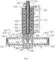
- Fig. 1 is an overall structural schematic of a gas analyzing apparatus 400 according to the present invention.
- the gas analyzing apparatus 400 comprises a sampling device and an ion mobility spectrum analysis device.
- the sampling device includes: a multi-capillary column 401 that comprises a plurality of capillary columns.
- the multi-capillary column 401 may be formed by clustering a plurality of independent capillary columns in parallel into a bundle.
- the multi-capillary column 401 may be formed by defining a plurality of capillary pores in parallel in one column.
- the multi-capillary column 401 may be formed of non-metallic material.
- the capillary column may be formed of glass material.
- the capillary column may be also formed of other materials.
- the multi-capillary column 401 is configured to have an inlet end and an outlet end substantially aligned with each other.
- a multi-capillary column is consisted of hundreds of capillary columns in parallel.
- each of the capillary columns coated with a layer of stationary phase on its inner surface. Any types of the stationary phase will be used relying on the demands. Due to its great separation ability, the multi-capillary column 401 is generally formed in a form of pen-shaped column having relatively shorter size (of 40 ⁇ 250mm), to achieve the separation function. The column having a relatively greater size may be coiled into a disc. Components of the mixed sample interact with the stationary phases of the capillary columns for different retention times so as to be separated from one another. Retention times for these capillary columns are in order of magnitude of seconds to minutes (generally, tens of seconds to several minutes, and the minimum peak width is several seconds).
- Structure of the multi-capillary column 401 owns the following advantages. Firstly, thousands of capillary columns are clustered so that the multi-capillary column 401 has greater capacity, which makes it to have a greater sensibility. Secondly, the capillary column in the multi-capillary column 401 is much finer in diameter, for example, the capillary column's inner diameter may be 20 ⁇ 100 ⁇ m, while conventional capillary column has an inner diameter of 0.25 ⁇ 0.53mm, that is, these capillary columns in the multi-capillary column 401 have greater separation effect, thus shorter capillary columns may achieve a better separation effect.
- the pen-shaped multi-capillary column 401 (of 40 ⁇ 250mm) has less pressure gradients than conventional capillary columns (generally of 30m), so the flow rate through the multi-capillary column 401 is greater in 2-3 orders of magnitude than that through the conventional capillary columns, and may be in a greater flow-rate range (of 20 ⁇ 150ml/min), accordingly, the multi-capillary column 401 enables not only fast separation but also isothermal separation.
- the multi-capillary column-IMS obtain an ability of approximately real-time separation and detection, and on the other hand, the multi-capillary column having shorter size helps to achieve a portable multi-capillary column-IMS.
- the sampling device further comprises a metallic sleeve 420 configured to enclose and protect the multi-capillary column 401.
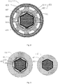
- Fig. 1 of the present disclosure shows a situation in which one metallic sleeve 420 is coupled around a regular hexagonal glass column, that is, the pen-shaped multi-capillary column 401 has a cross-section of regular hexagon.
- the multi-capillary column 401 may have a cross-section of any other shape, e.g., circular.
- the sampling device further comprises a temperature controlling system configured to couple with the multi-capillary column 401 so as to control a temperature within the multi-capillary column 401.
- the temperature controlling system of the sampling device comprises a thermal conductor casing 402 configured to be in a direct contact with the metallic sleeve 420 by which the multi-capillary column 401 is enclosed.
- the temperature controlling system may further comprise at least one heater 404 and at least one sensor 405 embedded within the thermal conductor casing 402. Cooperation of the at least one heater 404 and the at least one sensor 405 may achieve control of a temperature of the thermal conductor casing 402.
- Various types of heaters may be used.
- a plurality of heating rods 404 i.e., one or more heating rods 404 are embedded in the thermal conductor casing 402.
- the plurality of heating rods 404 may be distributed uniformly within the thermal conductor casing 402, so as to increase rapidly and evenly the temperature of the thermal conductor casing 402.
- Fig. 1 shows a situation in which one heating rod is used.
- Heating filaments may be embedded therein the thermal conductor casing 402 and arranged to facilitate the uniform heating.
- the thermal conductor casing 402 itself may be a kind of heating element for heating up.
- the sensor 405 may be provided adjacent to the metallic sleeve 420, so that the temperature measured by the sensor 405 is much closer to the temperature within the capillary columns.
- a plurality of the sensors 405 may be distributed uniformly with the thermal conductor casing 402 around the metallic sleeve 420.
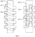
- the thermal conductor casing 402 comprises a plurality of protrusions 430 on an outer circumference of the thermal conductor casing 402 and spaces 403 defined among the plurality of protrusions 430. These spaces are served as grooves 403, or as fluid passages 403 through which a fluid passes, as shown in Fig. 2 .
- Sizes of these protrusions 430 may be the same as or different from one another. Spacings between adjacent protrusions 430 may be the same as or different from one another. For example, some of the protrusions 430 have relative greater size(s) while the rest of the protrusions 430 have relative smaller size(s). For example, if every two columns of protrusions 430 constitute a group, the spacing between every two groups of protrusions 430 is greater than that between two columns of protrusions 430 in each of the two groups. Also, the protrusions 430 may be arranged non-uniformly. It should be understood for those skilled in the art that the protrusions 430 may have other sizes and spacings and also may be arranged in other manners.
- the thermal conductor casing402 may be regarded as including two portions, one is a base of the thermal conductor casing 402 while the other one is a protrusion 430 of the thermal conductor casing 402.
- the base may have a relatively smaller radial thickness
- the protrusion 430 may have a relatively greater height. Provision of the plurality of protrusions 430 on the thermal conductor 402 helps the fluid to flow among the protrusions 430, so as to exchange heat with the thermal conductor casing 402 For example, gas may be introduced and flows among the plurality of protrusions 430, accelerating heat exchange between the plurality of protrusions 430 on the thermal conductor casing 402 and the introduced gas.
- the plurality of protrusions 430 can be served as heat sinks. Conduits through which the fluid passes may be wound around the plurality of protrusions 430. By the heat exchange between high-temperature fluid or low-temperature fluid within the conduits and the thermal conductor casing 402, temperature of the thermal conductor casing 402 is controllable.
- the base of the thermal conductor casing 402 has a relatively smaller thickness, and a heating film is disposed among the plurality of protrusions 430 and is configured for rise heating up the thermal conductor casing 402. Meanwhile, heat medium fluid conduits are disposed among the plurality of protrusions 430, for achieve drop in temperature via thermal transmission. With this arrangement in combination with the sensors 405, the temperature of the thermal conductor casing 402 may be controlled rapidly.
- the thermal conductor casing 402 has trenches where flowing heat medium fluid or heat medium fluid conduits are received, for thermal transmission.
- Fig. 4 shows a situation where fluid conduits are wound among the plurality of protrusions 430.
- the heat medium fluid conduits may sinuously extend among the plurality of protrusions 430, or the heat medium fluid conduits are spirally located around the plurality of protrusions 430 of the thermal conductor casing 402, so that a thermal transmission is implemented between the heat medium fluid conduits and the thermal conductor casing 402.
- the fluid conduits may be arranged in the passages or trenches defined by the plurality of protrusions 430 in any manner; here, the protrusions 430 not only are used to implement heat exchange with the heat medium fluid conduits, but also act to support the conduits.
- the plurality of protrusions 430 may be regarded as thermal dissipation protrusions 430 where heat is taken away directly by fluids.
- the plurality of protrusions 430 may be used as an arrangement for defining fluid passages among the plurality of protrusions and for fixation of the fluid passages.
- the sampling device may further comprise a housing 406 enclosing the temperature controlling system.
- the sampling device may further comprise a thermal insulation layer 408 disposed between the housing 406 and the thermal conductor casing 402.
- the housing 406 may enclose around the outer surface of the thermal conductor casing 402 in a sealing manner.
- the plurality of protrusions on the thermal conductor casing402 may be used to support the thermal insulation layer 408 and the housing 406.
- a plurality of passages is formed between the plurality of protrusions and the thermal insulation layer 408.
- Heat medium fluid conduits may be arranged at the outer circumference of the thermal conductor 402 to pass through these passages or the abovementioned trenches, for sufficiently thermal transmission.
- An air pump 418 may be provided to communicate with the abovementioned trenches 403 through conduits 417. Through the conduits 417, pressured gas is pumped by the air pump 418 into the trenches 403 among the plurality of protrusions 430, facilitating cooling or heating up the thermal conductor casing 402. In one embodiment, fluids may be introduced directly into the trenches formed among the plurality of protrusions 430, for heat exchange.
- the inlet end of the multi-capillary column 401 extends out of the housing 406 of the sampling device to a feeder.
- interfaces of the sampling device and the ion mobility spectrum analysis device are particularly important.
- the interfaces of the sampling device with the ion mobility spectrum analysis device function to introduce smoothly, without any quality degradation, the sample separated rapidly from the multi-capillary column 401 into the reaction region of the ion mobility spectrum analysis device.
- the gas analyzing apparatus 400 may further comprise a thermal insulation positioning device 411 located on a reaction region base 419 and configured for connection between the sampling device and the ion mobility spectrum analysis device, and for isolating a thermal transmission between the sampling device and the ion mobility spectrum analysis device, so that the sampling device and the ion mobility spectrum analysis device are independently controlled respectively in temperature.
- a thermal insulation positioning device 411 located on a reaction region base 419 and configured for connection between the sampling device and the ion mobility spectrum analysis device, and for isolating a thermal transmission between the sampling device and the ion mobility spectrum analysis device, so that the sampling device and the ion mobility spectrum analysis device are independently controlled respectively in temperature.
- the thermal insulation positioning device 411 comprises a first connection end connected to the outlet end of the sampling device, and a second connection end connected to the ion mobility spectrum analysis device. Specifically, the first connection end is connected and sealed at one end of the multi-capillary column. The second connection end has a shape that complements a shape of an opening in the reaction region base 419 of the ion mobility analysis device. Shape of the thermal insulation positioning device 411 is shown in the cross-sectional views of Fig. 1 and Fig. 3 .
- the thermal insulation positioning device 411 has a stepped shape, and, Fig. 3 shows the cross-sectional views along line B-B and line C-C, respectively.
- a gasket may be provided on an outer surface of a section of the thermal insulation positioning device 411.
- the gasket 413 may act in a sealing function.
- the thermal insulation positioning device 411 is connected there between.
- a good sealing is necessary to avoid leakage of the particles within the reaction region 414 or to prevent ambient gas from entering the reaction region 414 to adversely affect accuracy of the measurement.
- the thermal insulation positioning device 411 may be made of a plastic material, for example, PEEK, or Teflon.
- the thermal insulation positioning device 411 may be made of other non-metallic materials having high temperature resistant performance and thermal insulation performance. For example, it is made of a material such as refractory material, asbestos or the like.
- the metallic sleeve 420 is prevented from being close to the ionization region of the ion mobility spectrum analysis device, avoiding the metallic sleeve 420 from interfering zero electric field in the ionization region.
- the metallic sleeve 420 is kept out of the sample leading-in opening of the ion mobility spectrum analysis device.
- the metallic sleeve 420 is kept away from the sample leading-in opening of the ion mobility spectrum analysis device.
- the sample is fed directly into the reaction region 414 of the ion mobility spectrum analysis device, avoiding the problem in prior arts that gaseous material introduced into the ionization region 415 is broken, e.g., by high-energy ray beams, into ion fragments. Meanwhile, the gaseous material can be separated by the capillary columns, for meeting analytical requirements, and is fed into the reaction region 414, for analysis.
- the thermal insulation positioning device 411 may be integrated with the sampling device, which is advantageous in practice use.
- one end of the sampling device is sealed up by the thermal insulation positioning device 411, while the outlet end of the sampling device runs out of the thermal insulation positioning device 411, as shown in Fig. 1 .
- the outlet end of the sampling device including the thermal insulation positioning device 411 is shown in Fig. 1 . That is, the multi-capillary column 401 is enwrapped by the end of the thermal insulation positioning device 411, and, a part of the multi-capillary column is directly enwrapped by the non-metallic material of the thermal insulation positioning device 411.
- the thermal insulation positioning device 411 enables a convenient and direct insertion of the sampling device into the reaction cavity, namely the reaction region 414, of the ion mobility spectrum analysis device. It is especially important in a situation where a rapid analysis of the gas sample is required.
- the sampling device may be temperature-controlled independently. The temperature of the sampling device may be controlled independently in a preparation time. When the sampling device is in a desired temperature condition, it is inserted into the ion mobility spectrum analysis device. Connection and relative positions between the sampling device and the ion mobility spectrum analysis device are achieved by use of the thermal insulation positioning device 411.
- connection and disconnection between the sampling device and the ion mobility spectrum analysis device may be implemented conveniently, which has a positive significance in the practical inspection process, greatly facilitates inspections on different samples, facilitate transportation, and, achieves a reduced volume of the whole inspection system.
- a plurality of sampling devices may be equipped, which facilitates inspections on different samples and increase speed and accuracy of the inspection.
- a length of the metallic sleeve 420 of the multi-capillary column 401 is configured so that the metallic sleeve 420 does not extend into the ionization region 415 of the ion mobility spectrum analysis device when the multi-capillary column 401 is inserted into the reaction cavity 414 of the ion mobility spectrum analysis device.
- the end of the metallic sleeve 420 is terminated in the thermal insulation positioning device 411, for example, at a position shown in Fig. 1 .
- the location of the metallic sleeve 420 may be changed as long as the metallic sleeve 420 is kept out of the reaction region 414 where the ions are contained.
- the metallic sleeve 420 is kept out of, or is kept away from the sample leading-in opening of the ion mobility spectrum analysis device.
- the gas analyzing apparatus 400 further comprises an ion mobility spectrum analysis device adapted for analyzing a sample leaded-in by the sampling device.
- the ion mobility spectrum analysis device comprises a reaction cavity 414 for gas reaction between molecules of the sample and reaction ions, and the reaction cavity 414 has a sample leading-in opening for leading-in of the sample.
- the ion mobility spectrum analysis device further comprises an ionization region 415.
- the sampling device is positioned at an upper side of the ion mobility spectrum analysis device, and, the ionization region 415 is positioned at a lower side of the ion mobility spectrum analysis device. It is advantageous to arrange the sampling device to be opposed to the ionization region 415 of the ion mobility spectrum analysis device. Being different from the prior art technical concept that the sample is ionized after being introduced into the ionization region 415, the sampling device of the present invention is configured to keep the sample to be analyzed away from the ionization region 415 but to directly introduce the sample to be analyzed into the reaction region 414.
- the sample introduced into the ionization region 415 is broken into ion fragments, e.g., due to turbulence caused by non-linear gas passage. That is, the sample is introduced smoothly into the ion mobility spectrum analysis device while being separated rapidly.
- the ion mobility spectrum analysis device 412 comprises positive and negative dual mode migration tubes 422, 423, the reaction region 414 is located between the positive mode migration tube 422 and the negative mode migration tube 423, and, the ionization region 415 and the reaction region 414 are arranged separately and are communicated via an opening that can be closed and opened, as the arrangement shown in Fig. 1 .
- the ionization region 415 is located adjacent to a side of the reaction region 414.
- Carrier gas 416 such as air is introduced into the ionization region 415, and is ionized in ionization region 415 to generate positive reaction ion H + (H 2 O) n and negative reaction ion O 2 - (H 2 O) n .
- the electrically charged reaction ions are transmitted into the reaction region 414 and are collided with the sample molecules in the reaction region 414, so that the sample molecules are ionized to generate product ions.
- the sample gas is ionized together with the carrier gas. For example, bio-macromolecule is combined with hydrated proton or hydrated oxygen ion to form molecules with positive or negative charge.
- the positive mode migration tube 422 and the negative mode migration tube 423 each comprises an ion gate 424, a migration area, a suppressor grid 427 and a Faraday's disc 428.
- the migration area may be defined by stainless steel protective rings 425 and ceramic insulating rings 426 which are arranged in series. Sample particles with positive charge are detected in the positive mode migration tube, and sample particles with negative charge are detected in the negative mode migration tube.
- the carrier gas 416 is ionized in the ionization region 415 of the ion mobility spectrum analysis device to generate reactive ions.
- the reactive ions are swept, by the carrier gas 416 from the ion mobility spectrum analysis device, into the reaction region 414 through the carrier gas inlet of the ionization region 415.
- the reactive ions encounter the sample separated by the multi-capillary column 401 to produce an electrophilic reaction of adsorption, so that the sample molecules adsorb the reactive ions to generate charged product ions, and the positive and negative charged productions are guided into and separated in the positive mode migration tube 422 and the negative mode migration tube 423, respectively, with the promotions of positive and negative electrical fields within the migration tubes, and are detected by the Faraday's discs 428 at either end of the migration tubes.
- Other designs and principles of the ion mobility spectrum analysis device 412 may refer to a Chinese patent application No. 200810119974.6 .
Description
- The present application relates to the field of safety detecting technology, and in particular, to a gas analyzing apparatus comprising a sampling device.
- Currently, Gas chromatography (GC) and ion mobility spectrometry (IMS) combination technology (GC-IMS) is used to pre-separate a sample, based on prominent separating performance of GC for complex components, to separate a mixture into single components, and transfer them to an IMS detector for detection. It has been confirmed that such combination technology extends resolution of IMS detection for chemical component by increase retention time information of GC, achieves higher detection limit and widens linear dynamic range. The GC-IMS combination technology is thus rapidly developed in recent years. However, conventional GC analysis process is hard to meet requirements of fast detection in situ as a complete GC analysis spends more than ten minutes and needs a huge oven to obtain high temperature condition.
- In addition, IMS is currently widely equipped with radioactivity β source, which may radiate high-energy primary electron (63Ni: 67keV, 3H: 18keV).The existing apparatus is configured to directly introduce a separated sample into an ionization area, where part of the sample is broken by the high-energy β ray into fragment ions, or is ionized as molecular ions with positive charge. On one hand, the fragment ions may result in an increased wave crest of reactive ion (by monitoring RIP, it may be mainly (H2O)nH+ in a positive mode, or it may be mainly O2 -(H2O)2 in a negative mode), which may disturb base line and decrease resolution of IMS detection. Particularly, during detection of biomacromolecule such as protein molecular or nucleic acid, election ionization source will render more complex fragments, which will form a map that is hard to be identified. For this reason, it is difficult for a GC-IMS spectrometer to be applied in the field of detecting organic macromoleculars. On the other hand, the fragment ions or molecular ions with positive charge may be reacted with reactive ions to obtain an unresolvable ion spectrum, in which the lines in the spectrum are disordered and bring troublesome to analysis. It is desired to provide an accurate IMS detection.
-
CN203798779U discloses gas chromatograph and ion mobility spectrometer combined equipment.EP0891543A1 discloses a recirculating filtration system for use with a transportable ion mobility spectrometer.US2007/029477A1 discusses ion mobility based systems, methods and devices for analyzing samples.US2007/256474A1 discloses a gas chromatograph for the analysis of gas samples.US5228514A discloses a gas trap apparatus for trapping gaseous fraction of mixtures.US 6333088 B1 discusses capillary assemblies for separative transport such as electrophoresis and gas solid partition chromatography, and in particular a single conduit that contains multiple capillary sized passages.US 2010/089811 A1 discloses a preparative column design used in high performance liquid chromatography technology. - It is an object of the present invention to provide a gas analyzing apparatus, which at least partially overcomes or eliminates disadvantages, including inconvenient use, large volume and easy-introduced analytical error, of analyzing apparatuses in prior arts. In accordance with the present invention, there is provided a gas analyzing apparatus as recited by
claim 1. Preferred features are set out in the dependent claims. - The gas analyzing apparatus of the present invention may achieve at least the following advantages:
- 1) Components separated by the multi-capillary column are guided directly into the reaction region in the middle of the dual-mode migration tubes (i.e. at the same time has positive mode migration tube and negative mode migration tube respectively analyses cation and anion), instead of into the ionization region, which achieves the purpose of avoiding generations of fragment ions, and also enables the GC-IMS to identify positive and negative ions. As a result, the spectrometer is able to be responsive to both positive and negative electrical affinity of macromolecules, which makes up for shortcomings of the prior art technologies and broadens range of materials selectable for detection by the multi-capillary column-IMS device.
- 2) No switching element is required for interfaces of the multi-capillary column-IMS device, and the ports of the multi-capillary column are coupled directly with the IMS device, which avoids turbulent flow induced due to turn around of the switching element, and effectively improves detection sensitivity and resolution rate of the IMS device. Provided between the multi-capillary column and a reaction region base of the IMS device may be a thermal insulation positioning device, which has both positioning and thermal insulation functions, is simple in structure, and is easy to be mounted and operated, thereby omitting additional provision of the switching element and temperature controlling system design there for.
- 3) The heating elements of the multi-capillary column are embedded evenly within the thermal conductor casing, and the benefits of this design are in that rapid heating of the multi-capillary column is achieved, uniform heating of the multi-capillary column is ensured, the sample gasification and separation are ensured and separation discrimination is reduced.
- 4) A plurality of protrusions are provided on the thermal conductor casing such that heat radiating conduits may be embedded and wrapped in spaces among the plurality of protrusions. The coolant flowing within the conduits may bring heat away to quickly cool the multi-capillary column, which is useful for the multi-capillary column -ion mobility spectrum analysis device to quickly cope with variations in boiling point of the matters when performing a next measurement during a successive measurement period.
- 5) Cooperation and control of the thermal conductor casing, heat radiating conduits, heating elements, pumps and controllers achieve a programmed heating effect of the multi-capillary column. The application field of the multi-capillary column -ion mobility spectrum analysis device combined spectrometer can be extended to cope with separation of components of samples in a wide range of boiling points, which improves selective range of the substances to be analyzed.
-
-
Fig. 1 is a schematic sectional view of a gas analyzing apparatus according to the present invention; -
Fig. 2 is a sectional view of a gas analyzing apparatus according to the present invention along a line A-A; -
Fig. 3 is a sectional view of a gas analyzing apparatus according the present invention along a line B-B and a line C-C; and -
Fig. 4 shows an arrangement of a plurality of protrusions on a thermal conductor and fluid conduits located between the plurality of protrusions of a gas analyzing apparatus according to the present invention. - The present invention will be explained hereafter with reference to the attached drawings.
-
Fig. 1 is an overall structural schematic of a gas analyzing apparatus 400 according to the present invention. The gas analyzing apparatus 400 comprises a sampling device and an ion mobility spectrum analysis device. - The sampling device includes: a
multi-capillary column 401 that comprises a plurality of capillary columns. Themulti-capillary column 401 may be formed by clustering a plurality of independent capillary columns in parallel into a bundle. Themulti-capillary column 401 may be formed by defining a plurality of capillary pores in parallel in one column. Themulti-capillary column 401 may be formed of non-metallic material. For example, generally, the capillary column may be formed of glass material. The capillary column may be also formed of other materials. Themulti-capillary column 401 is configured to have an inlet end and an outlet end substantially aligned with each other. A multi-capillary column is consisted of hundreds of capillary columns in parallel. For example, 500∼5000 capillary columns, each having an inner diameter of 20∼100µm, preferably of about 40µm, in parallel are clustered within a glass column having a cross-section of regular hexagon. Each of the capillary columns coated with a layer of stationary phase on its inner surface. Any types of the stationary phase will be used relying on the demands. Due to its great separation ability, themulti-capillary column 401 is generally formed in a form of pen-shaped column having relatively shorter size (of 40∼250mm), to achieve the separation function. The column having a relatively greater size may be coiled into a disc. Components of the mixed sample interact with the stationary phases of the capillary columns for different retention times so as to be separated from one another. Retention times for these capillary columns are in order of magnitude of seconds to minutes (generally, tens of seconds to several minutes, and the minimum peak width is several seconds). - Structure of the
multi-capillary column 401 owns the following advantages. Firstly, thousands of capillary columns are clustered so that themulti-capillary column 401 has greater capacity, which makes it to have a greater sensibility. Secondly, the capillary column in themulti-capillary column 401 is much finer in diameter, for example, the capillary column's inner diameter may be 20∼100µm, while conventional capillary column has an inner diameter of 0.25∼0.53mm, that is, these capillary columns in themulti-capillary column 401 have greater separation effect, thus shorter capillary columns may achieve a better separation effect. Thirdly, the pen-shaped multi-capillary column 401 (of 40∼250mm) has less pressure gradients than conventional capillary columns (generally of 30m), so the flow rate through themulti-capillary column 401 is greater in 2-3 orders of magnitude than that through the conventional capillary columns, and may be in a greater flow-rate range (of 20∼150ml/min), accordingly, themulti-capillary column 401 enables not only fast separation but also isothermal separation. With the above advantages, on one hand, the multi-capillary column-IMS obtain an ability of approximately real-time separation and detection, and on the other hand, the multi-capillary column having shorter size helps to achieve a portable multi-capillary column-IMS. - In order for strengthening protection for the glass column, enhancing whole strength of the multi-capillary column and preventing them from accidentally cracking, the sampling device further comprises a
metallic sleeve 420 configured to enclose and protect themulti-capillary column 401.Fig. 1 of the present disclosure shows a situation in which onemetallic sleeve 420 is coupled around a regular hexagonal glass column, that is, the pen-shapedmulti-capillary column 401 has a cross-section of regular hexagon. Themulti-capillary column 401 may have a cross-section of any other shape, e.g., circular. - The sampling device further comprises a temperature controlling system configured to couple with the
multi-capillary column 401 so as to control a temperature within themulti-capillary column 401. - The temperature controlling system of the sampling device comprises a thermal conductor casing 402 configured to be in a direct contact with the
metallic sleeve 420 by which themulti-capillary column 401 is enclosed. The temperature controlling system may further comprise at least oneheater 404 and at least onesensor 405 embedded within thethermal conductor casing 402. Cooperation of the at least oneheater 404 and the at least onesensor 405 may achieve control of a temperature of thethermal conductor casing 402. Various types of heaters may be used. For example, a plurality ofheating rods 404, i.e., one ormore heating rods 404 are embedded in thethermal conductor casing 402. The plurality ofheating rods 404 may be distributed uniformly within thethermal conductor casing 402, so as to increase rapidly and evenly the temperature of thethermal conductor casing 402.Fig. 1 shows a situation in which one heating rod is used. Heating filaments may be embedded therein thethermal conductor casing 402 and arranged to facilitate the uniform heating. For example, thethermal conductor casing 402 itself may be a kind of heating element for heating up. - The
sensor 405 may be provided adjacent to themetallic sleeve 420, so that the temperature measured by thesensor 405 is much closer to the temperature within the capillary columns. A plurality of thesensors 405 may be distributed uniformly with thethermal conductor casing 402 around themetallic sleeve 420. - The
thermal conductor casing 402 comprises a plurality ofprotrusions 430 on an outer circumference of thethermal conductor casing 402 andspaces 403 defined among the plurality ofprotrusions 430. These spaces are served asgrooves 403, or asfluid passages 403 through which a fluid passes, as shown inFig. 2 . - Sizes of these
protrusions 430 may be the same as or different from one another. Spacings betweenadjacent protrusions 430 may be the same as or different from one another. For example, some of theprotrusions 430 have relative greater size(s) while the rest of theprotrusions 430 have relative smaller size(s). For example, if every two columns ofprotrusions 430 constitute a group, the spacing between every two groups ofprotrusions 430 is greater than that between two columns ofprotrusions 430 in each of the two groups. Also, theprotrusions 430 may be arranged non-uniformly. It should be understood for those skilled in the art that theprotrusions 430 may have other sizes and spacings and also may be arranged in other manners. - In other words, the thermal conductor casing402 may be regarded as including two portions, one is a base of the
thermal conductor casing 402 while the other one is aprotrusion 430 of thethermal conductor casing 402. In one embodiment, the base may have a relatively smaller radial thickness, and theprotrusion 430 may have a relatively greater height. Provision of the plurality ofprotrusions 430 on thethermal conductor 402 helps the fluid to flow among theprotrusions 430, so as to exchange heat with thethermal conductor casing 402 For example, gas may be introduced and flows among the plurality ofprotrusions 430, accelerating heat exchange between the plurality ofprotrusions 430 on thethermal conductor casing 402 and the introduced gas. Here, the plurality ofprotrusions 430 can be served as heat sinks. Conduits through which the fluid passes may be wound around the plurality ofprotrusions 430. By the heat exchange between high-temperature fluid or low-temperature fluid within the conduits and thethermal conductor casing 402, temperature of thethermal conductor casing 402 is controllable. - The base of the
thermal conductor casing 402 has a relatively smaller thickness, and a heating film is disposed among the plurality ofprotrusions 430 and is configured for rise heating up thethermal conductor casing 402. Meanwhile, heat medium fluid conduits are disposed among the plurality ofprotrusions 430, for achieve drop in temperature via thermal transmission. With this arrangement in combination with thesensors 405, the temperature of thethermal conductor casing 402 may be controlled rapidly. - With arrangement of the plurality of
protrusions 430, thethermal conductor casing 402 has trenches where flowing heat medium fluid or heat medium fluid conduits are received, for thermal transmission. Specifically,Fig. 4 shows a situation where fluid conduits are wound among the plurality ofprotrusions 430. The heat medium fluid conduits may sinuously extend among the plurality ofprotrusions 430, or the heat medium fluid conduits are spirally located around the plurality ofprotrusions 430 of thethermal conductor casing 402, so that a thermal transmission is implemented between the heat medium fluid conduits and thethermal conductor casing 402. It should be understood that, the fluid conduits may be arranged in the passages or trenches defined by the plurality ofprotrusions 430 in any manner; here, theprotrusions 430 not only are used to implement heat exchange with the heat medium fluid conduits, but also act to support the conduits. - A provision of the plurality of
protrusions 430 is advantageous. The plurality ofprotrusions 430 may be regarded asthermal dissipation protrusions 430 where heat is taken away directly by fluids. The plurality ofprotrusions 430 may be used as an arrangement for defining fluid passages among the plurality of protrusions and for fixation of the fluid passages. - The sampling device may further comprise a
housing 406 enclosing the temperature controlling system. In one embodiment, the sampling device may further comprise athermal insulation layer 408 disposed between thehousing 406 and thethermal conductor casing 402. Thehousing 406 may enclose around the outer surface of thethermal conductor casing 402 in a sealing manner. When thethermal conductor casing 402 is enclosed by thethermal insulation layer 408 and thehousing 406, the plurality of protrusions on the thermal conductor casing402 may be used to support thethermal insulation layer 408 and thehousing 406. As shown inFig. 1 , a plurality of passages is formed between the plurality of protrusions and thethermal insulation layer 408. Heat medium fluid conduits may be arranged at the outer circumference of thethermal conductor 402 to pass through these passages or the abovementioned trenches, for sufficiently thermal transmission. - An
air pump 418 may be provided to communicate with theabovementioned trenches 403 throughconduits 417. Through theconduits 417, pressured gas is pumped by theair pump 418 into thetrenches 403 among the plurality ofprotrusions 430, facilitating cooling or heating up thethermal conductor casing 402. In one embodiment, fluids may be introduced directly into the trenches formed among the plurality ofprotrusions 430, for heat exchange. - The inlet end of the multi-capillary column 401extends out of the
housing 406 of the sampling device to a feeder. A portion of themetallic sleeve 420, along with themulti-capillary column 401, may also extend out of thehousing 406. - Since a flow velocity of the sample in the
multi-capillary column 401 is greater than conventional capillary column, interfaces of the sampling device and the ion mobility spectrum analysis device are particularly important. The interfaces of the sampling device with the ion mobility spectrum analysis device function to introduce smoothly, without any quality degradation, the sample separated rapidly from themulti-capillary column 401 into the reaction region of the ion mobility spectrum analysis device. - The gas analyzing apparatus 400 may further comprise a thermal
insulation positioning device 411 located on areaction region base 419 and configured for connection between the sampling device and the ion mobility spectrum analysis device, and for isolating a thermal transmission between the sampling device and the ion mobility spectrum analysis device, so that the sampling device and the ion mobility spectrum analysis device are independently controlled respectively in temperature. - The thermal
insulation positioning device 411 comprises a first connection end connected to the outlet end of the sampling device, and a second connection end connected to the ion mobility spectrum analysis device. Specifically, the first connection end is connected and sealed at one end of the multi-capillary column. The second connection end has a shape that complements a shape of an opening in thereaction region base 419 of the ion mobility analysis device. Shape of the thermalinsulation positioning device 411 is shown in the cross-sectional views ofFig. 1 andFig. 3 . The thermalinsulation positioning device 411 has a stepped shape, and,Fig. 3 shows the cross-sectional views along line B-B and line C-C, respectively. In one embodiment, a gasket may be provided on an outer surface of a section of the thermalinsulation positioning device 411. Thegasket 413 may act in a sealing function. When the sampling device is inserted into the ion mobility spectrum analysis device, the thermalinsulation positioning device 411 is connected there between. Here, a good sealing is necessary to avoid leakage of the particles within thereaction region 414 or to prevent ambient gas from entering thereaction region 414 to adversely affect accuracy of the measurement. - The thermal
insulation positioning device 411 may be made of a plastic material, for example, PEEK, or Teflon. The thermalinsulation positioning device 411 may be made of other non-metallic materials having high temperature resistant performance and thermal insulation performance. For example, it is made of a material such as refractory material, asbestos or the like. With the thermalinsulation positioning device 411, the outlet end of themulti-capillary column 401 made of non-metallic material is inserted directly into a reaction cavity of the ion mobility spectrum analysis device, namely, into thereaction region 414 of the ion mobility spectrum analysis device, through a sample leading-in opening of the ion mobility spectrum analysis device. Meanwhile, themetallic sleeve 420 is prevented from being close to the ionization region of the ion mobility spectrum analysis device, avoiding themetallic sleeve 420 from interfering zero electric field in the ionization region. Themetallic sleeve 420 is kept out of the sample leading-in opening of the ion mobility spectrum analysis device. Themetallic sleeve 420 is kept away from the sample leading-in opening of the ion mobility spectrum analysis device. - With this arrangement, the sample is fed directly into the
reaction region 414 of the ion mobility spectrum analysis device, avoiding the problem in prior arts that gaseous material introduced into theionization region 415 is broken, e.g., by high-energy ray beams, into ion fragments. Meanwhile, the gaseous material can be separated by the capillary columns, for meeting analytical requirements, and is fed into thereaction region 414, for analysis. - The thermal
insulation positioning device 411 may be integrated with the sampling device, which is advantageous in practice use. In this case, one end of the sampling device is sealed up by the thermalinsulation positioning device 411, while the outlet end of the sampling device runs out of the thermalinsulation positioning device 411, as shown inFig. 1 . Here, the outlet end of the sampling device including the thermalinsulation positioning device 411 is shown inFig. 1 . That is, themulti-capillary column 401 is enwrapped by the end of the thermalinsulation positioning device 411, and, a part of the multi-capillary column is directly enwrapped by the non-metallic material of the thermalinsulation positioning device 411. - Arrangement of the thermal
insulation positioning device 411 enables a convenient and direct insertion of the sampling device into the reaction cavity, namely thereaction region 414, of the ion mobility spectrum analysis device. It is especially important in a situation where a rapid analysis of the gas sample is required. The sampling device may be temperature-controlled independently. The temperature of the sampling device may be controlled independently in a preparation time. When the sampling device is in a desired temperature condition, it is inserted into the ion mobility spectrum analysis device. Connection and relative positions between the sampling device and the ion mobility spectrum analysis device are achieved by use of the thermalinsulation positioning device 411. Due to thermal insulation property and rigidity of the thermalinsulation positioning device 411, accuracy of the measurement of the ion mobility spectrum analysis device will not be affected by the temperature of the sampling device, and, a positional relationship between the sampling device and the ion mobility spectrum analysis device may be determined. With this arrangement, connection and disconnection between the sampling device and the ion mobility spectrum analysis device may be implemented conveniently, which has a positive significance in the practical inspection process, greatly facilitates inspections on different samples, facilitate transportation, and, achieves a reduced volume of the whole inspection system. For example, a plurality of sampling devices may be equipped, which facilitates inspections on different samples and increase speed and accuracy of the inspection. - A length of the
metallic sleeve 420 of themulti-capillary column 401 is configured so that themetallic sleeve 420 does not extend into theionization region 415 of the ion mobility spectrum analysis device when themulti-capillary column 401 is inserted into thereaction cavity 414 of the ion mobility spectrum analysis device. The end of themetallic sleeve 420 is terminated in the thermalinsulation positioning device 411, for example, at a position shown inFig. 1 . However, it should be noted that the location of themetallic sleeve 420 may be changed as long as themetallic sleeve 420 is kept out of thereaction region 414 where the ions are contained. For example, themetallic sleeve 420 is kept out of, or is kept away from the sample leading-in opening of the ion mobility spectrum analysis device. - The gas analyzing apparatus 400 further comprises an ion mobility spectrum analysis device adapted for analyzing a sample leaded-in by the sampling device. The ion mobility spectrum analysis device comprises a
reaction cavity 414 for gas reaction between molecules of the sample and reaction ions, and thereaction cavity 414 has a sample leading-in opening for leading-in of the sample. The ion mobility spectrum analysis device further comprises anionization region 415. - Referring to
Fig. 1 , the sampling device is positioned at an upper side of the ion mobility spectrum analysis device, and, theionization region 415 is positioned at a lower side of the ion mobility spectrum analysis device. It is advantageous to arrange the sampling device to be opposed to theionization region 415 of the ion mobility spectrum analysis device. Being different from the prior art technical concept that the sample is ionized after being introduced into theionization region 415, the sampling device of the present invention is configured to keep the sample to be analyzed away from theionization region 415 but to directly introduce the sample to be analyzed into thereaction region 414. It advantageously prevents generation of fragment ions, and avoids the problem in the prior arts that the sample introduced into theionization region 415 is broken into ion fragments, e.g., due to turbulence caused by non-linear gas passage. That is, the sample is introduced smoothly into the ion mobility spectrum analysis device while being separated rapidly. - The ion mobility
spectrum analysis device 412 comprises positive and negative dualmode migration tubes reaction region 414 is located between the positivemode migration tube 422 and the negativemode migration tube 423, and, theionization region 415 and thereaction region 414 are arranged separately and are communicated via an opening that can be closed and opened, as the arrangement shown inFig. 1 . For example, theionization region 415 is located adjacent to a side of thereaction region 414. -
Carrier gas 416 such as air is introduced into theionization region 415, and is ionized inionization region 415 to generate positive reaction ion H+(H2O)n and negative reaction ion O2 -(H2O)n. The electrically charged reaction ions are transmitted into thereaction region 414 and are collided with the sample molecules in thereaction region 414, so that the sample molecules are ionized to generate product ions. It is different from the prior art where the sample gas is ionized together with the carrier gas. For example, bio-macromolecule is combined with hydrated proton or hydrated oxygen ion to form molecules with positive or negative charge. The positivemode migration tube 422 and the negativemode migration tube 423 each comprises anion gate 424, a migration area, asuppressor grid 427 and a Faraday'sdisc 428. The migration area may be defined by stainless steelprotective rings 425 and ceramicinsulating rings 426 which are arranged in series. Sample particles with positive charge are detected in the positive mode migration tube, and sample particles with negative charge are detected in the negative mode migration tube. - Specifically, the
carrier gas 416 is ionized in theionization region 415 of the ion mobility spectrum analysis device to generate reactive ions. The reactive ions are swept, by thecarrier gas 416 from the ion mobility spectrum analysis device, into thereaction region 414 through the carrier gas inlet of theionization region 415. In thereaction region 414, the reactive ions encounter the sample separated by themulti-capillary column 401 to produce an electrophilic reaction of adsorption, so that the sample molecules adsorb the reactive ions to generate charged product ions, and the positive and negative charged productions are guided into and separated in the positivemode migration tube 422 and the negativemode migration tube 423, respectively, with the promotions of positive and negative electrical fields within the migration tubes, and are detected by the Faraday'sdiscs 428 at either end of the migration tubes. Other designs and principles of the ion mobilityspectrum analysis device 412 may refer to a Chinese patent application No.200810119974.6
Claims (12)
- A gas analyzing apparatus (400), comprising:a sampling device, comprising: a multi-capillary column (401) consisting of a plurality of capillary columns and having an inlet end and an outlet end, and a temperature controlling system configured to couple with the multi-capillary column so as to control a temperature within the multi-capillary column; andan ion mobility spectrum analysis device adapted for analyzing a gas leaded-in by the sampling device and comprising a reaction cavity (414) for gas reaction between sample molecules and reaction ions, the reaction cavity having a sampling opening for leading-in of the gas;wherein, the outlet end of the multi-capillary column is inserted directly into the reaction cavity of the ion mobility spectrum analysis device through the sampling opening of the ion mobility spectrum analysis device;characterised in that, the sampling device further comprises a metallic sleeve (420) configured to enclose and protect the multi-capillary column (401), wherein a length of the metallic sleeve for the multi-capillary column is configured so that the metallic sleeve does not extend into the sampling opening of the ion mobility spectrum analysis device when the multi-capillary column is inserted into the reaction cavity (414) of the ion mobility spectrum analysis device;the temperature controlling system further comprises a thermal conductor casing (402) configured to be in a direct contact with the metallic sleeve by which the multi-capillary column is enclosed; andthe thermal conductor casing comprises a plurality of protrusions (430) on an outer circumference of the thermal conductor casing, the plurality of protrusions being configured to define spaces (403) there among in which fluid passages are arranged or through which a fluid passes.
- The gas analyzing apparatus according to claim 1,
wherein the temperature controlling system further comprises at least one heater (404) and at least one sensor (405) which are embedded within the thermal conductor casing. - The gas analyzing apparatus according to either claim 1 or 2, wherein, the gas analyzing apparatus further comprises a thermal insulation positioning device (411) configured for connection between the sampling device and the ion mobility spectrum analysis device, and for isolating a thermal transmission between the sampling device and the ion mobility spectrum analysis device, and wherein the sampling device and the ion mobility spectrum analysis device are independently controllable respectively in temperature.
- The gas analyzing apparatus according to claim 3, wherein, the thermal insulation positioning device comprises a first connection end connected to the outlet end of the sampling device and sealed at one end of the multi-capillary column, and a second connection end connected to the ion mobility spectrum analysis device and having a shape that complements a shape of the opening of the reaction cavity of the ion mobility analysis device.
- The gas analyzing apparatus according to claim 3, wherein, the thermal insulation positioning device is formed of a non-metallic material with high temperature resistance and thermal insulation performances.
- The gas analyzing apparatus according to either claim 1 or 2, wherein, the capillary columns are formed of non-metallic material.
- The gas analyzing apparatus according to either claim 1 or 2, wherein, the capillary columns have a diameter in a range from 40µm to 100µm.
- The gas analyzing apparatus according to claim 1, wherein, heat medium fluid conduits goes through the plurality of protrusions in a zigzag manner or in a manner that the heat medium fluid conduits goes through the plurality of protrusions spirally around the thermal conductor, so that heat is transferred between the heat medium fluid conduits and the thermal conductor casing.
- The gas analyzing apparatus according to either claim 1 or 2, wherein the sampling device further comprises a housing (406) enclosing the temperature controlling system.
- The gas analyzing apparatus according to claim 9, wherein, the sampling device further comprises a thermal insulation layer (408) disposed between the housing and the thermal conductor casing.
- The gas analyzing apparatus according to claim 10, wherein, the thermal insulation layer is supported by the plurality of protrusions on the thermal conductor casing.
- The gas analyzing apparatus according to either claim 1 or 2, wherein, the ion mobility spectrum analysis device is a positive and negative ion dual mode migration tube comprising a positive ion migration tube and a negative ion migration tube, and, the ion mobility spectrum analysis device comprises an ionization region configured to ionize the leading-in carrier gas into reactive ions and feed the reactive ions to a reaction region, wherein, the ionization region is provided at a side of the ion mobility spectrum analysis device opposite to the outlet end of the multi-capillary column.
Priority Applications (1)
| Application Number | Priority Date | Filing Date | Title |
|---|---|---|---|
| PL15875162T PL3101418T3 (en) | 2014-12-31 | 2015-12-24 | Gas analyzing apparatus comprising a temperature controlling system for the capillary sampling device |
Applications Claiming Priority (2)
| Application Number | Priority Date | Filing Date | Title |
|---|---|---|---|
| CN201410855715.5A CN104515824B (en) | 2014-12-31 | 2014-12-31 | Gaseous substance analytical equipment and gas phase gatherer |
| PCT/CN2015/098665 WO2016107484A1 (en) | 2014-12-31 | 2015-12-24 | Gas phase substance analysis apparatus and gas phase importing apparatus |
Publications (3)
| Publication Number | Publication Date |
|---|---|
| EP3101418A1 EP3101418A1 (en) | 2016-12-07 |
| EP3101418A4 EP3101418A4 (en) | 2017-08-09 |
| EP3101418B1 true EP3101418B1 (en) | 2019-10-02 |
Family
ID=52791443
Family Applications (1)
| Application Number | Title | Priority Date | Filing Date |
|---|---|---|---|
| EP15875162.8A Not-in-force EP3101418B1 (en) | 2014-12-31 | 2015-12-24 | Gas analyzing apparatus comprising a temperature controlling system for the capillary sampling device |
Country Status (7)
| Country | Link |
|---|---|
| US (1) | US9772306B2 (en) |
| EP (1) | EP3101418B1 (en) |
| JP (1) | JP6359109B2 (en) |
| CN (1) | CN104515824B (en) |
| HK (1) | HK1209480A1 (en) |
| PL (1) | PL3101418T3 (en) |
| WO (1) | WO2016107484A1 (en) |
Families Citing this family (10)
| Publication number | Priority date | Publication date | Assignee | Title |
|---|---|---|---|---|
| CN104515824B (en) | 2014-12-31 | 2016-08-24 | 同方威视技术股份有限公司 | Gaseous substance analytical equipment and gas phase gatherer |
| CN106645472A (en) * | 2016-12-08 | 2017-05-10 | 同方威视技术股份有限公司 | Gas chromatography-ion mobility spectrometry device |
| DE102017201677A1 (en) | 2017-02-02 | 2018-08-02 | bentekk GmbH | Portable gas analyzer with compact measuring device |
| CN108614050A (en) * | 2018-05-14 | 2018-10-02 | 清华大学 | The preparation method of sampling tube bank, sampling analysis equipment and sampling tube bank |
| CN110243664B (en) * | 2019-06-24 | 2020-09-08 | 北京大学 | Online enrichment device and application of atmospheric gas phase volatile/semi-volatile organic compounds |
| CN112285216A (en) * | 2019-07-23 | 2021-01-29 | 同方威视技术股份有限公司 | Fumigant detector and detection method |
| CN111337598B (en) * | 2020-05-18 | 2020-09-11 | 同方威视技术股份有限公司 | Trace detection device |
| CN112539970B (en) * | 2020-12-03 | 2022-10-11 | 安徽德鑫源食品有限公司 | Flour sampling device |
| CN112683835A (en) * | 2020-12-18 | 2021-04-20 | 上海集成电路研发中心有限公司 | Mixed gas detection device and system |
| JPWO2022254523A1 (en) * | 2021-05-31 | 2022-12-08 |
Citations (3)
| Publication number | Priority date | Publication date | Assignee | Title |
|---|---|---|---|---|
| US6333088B1 (en) * | 1999-01-13 | 2001-12-25 | Uop Llc | Compound capillary assembly and use in separative transport |
| US20100089811A1 (en) * | 2008-10-14 | 2010-04-15 | Yury Zelechonok | HPLC preparative column design |
| EP3242316A1 (en) * | 2014-12-31 | 2017-11-08 | Nuctech Company Limited | Detection device and detection method |
Family Cites Families (24)
| Publication number | Priority date | Publication date | Assignee | Title |
|---|---|---|---|---|
| JPS6479652A (en) * | 1987-09-21 | 1989-03-24 | Shimadzu Corp | Gas chromatograph mass spectrometer |
| US5228514A (en) * | 1992-11-19 | 1993-07-20 | Ruska Laboratories, Inc. | Gas trap apparatus |
| DE69637079T2 (en) * | 1995-10-16 | 2008-01-24 | Thermo Orion Inc., Beverly | HOCHGESCHWINDIGKEITSCHROMATOGRAPHIE |
| WO1997038302A1 (en) * | 1996-04-04 | 1997-10-16 | Mine Safety Appliances Company | Recirculating filtration system for use with a transportable ion mobility spectrometer |
| AU2668099A (en) * | 1998-02-11 | 1999-08-30 | Lawrence V. Haley | Hand-held detection system using gc/ims |
| JP2000314731A (en) * | 1999-05-06 | 2000-11-14 | Shimadzu Corp | Gas chromatograph device |
| US6815668B2 (en) * | 1999-07-21 | 2004-11-09 | The Charles Stark Draper Laboratory, Inc. | Method and apparatus for chromatography-high field asymmetric waveform ion mobility spectrometry |
| JP2003045451A (en) * | 2001-07-31 | 2003-02-14 | Toyota Motor Corp | Fuel cell |
| FI117179B (en) * | 2004-01-23 | 2006-07-14 | Environics Oy | Gas chromatograph |
| US7608818B2 (en) * | 2005-04-29 | 2009-10-27 | Sionex Corporation | Compact gas chromatography and ion mobility based sample analysis systems, methods, and devices |
| US7351960B2 (en) * | 2005-05-16 | 2008-04-01 | Thermo Finnigan Llc | Enhanced ion desolvation for an ion mobility spectrometry device |
| US9523657B2 (en) | 2006-02-14 | 2016-12-20 | Excellims Corporation | Practical ion mobility spectrometer apparatus and methods for chemical and/or biological detection |
| CN101382526A (en) * | 2007-09-05 | 2009-03-11 | 中国科学院大连化学物理研究所 | Directly heating rapid programmed temperature gas chromatography column |
| DE102007052801B4 (en) | 2007-11-06 | 2010-10-07 | Bruker Daltonik Gmbh | Ion mobility spectrometer with substance collector |
| CN101728208B (en) | 2008-10-20 | 2012-09-26 | 同方威视技术股份有限公司 | Ion gate and method of bipolar ion mobility spectrometry |
| CN201917559U (en) * | 2010-11-30 | 2011-08-03 | 中国科学院大连化学物理研究所 | Gas chromatography and bipolar ion mobility spectrometry combination device |
| US20130180405A1 (en) * | 2012-01-13 | 2013-07-18 | Ron W. Currie | Gas Chromatography Capillary Devices and Methods |
| US8841611B2 (en) * | 2012-11-30 | 2014-09-23 | Agilent Technologies, Inc. | Multi-capillary column and high-capacity ionization interface for GC-MS |
| CN203798779U (en) | 2013-12-27 | 2014-08-27 | 同方威视技术股份有限公司 | Gas chromatograph and ion mobility spectrometer combined equipment |
| CN104749264B (en) * | 2013-12-27 | 2016-08-17 | 同方威视技术股份有限公司 | Gas chromatograph is combined equipment with ionic migration spectrometer |
| CN104020237B (en) * | 2014-06-24 | 2016-01-20 | 武汉矽感科技有限公司 | Can with the FastGC post modifying device of ionic migration spectrometer coupling |
| CN204424206U (en) * | 2014-12-31 | 2015-06-24 | 同方威视技术股份有限公司 | Checkout equipment |
| CN204389459U (en) * | 2014-12-31 | 2015-06-10 | 同方威视技术股份有限公司 | Gaseous substance analytical equipment and gas phase gatherer |
| CN104515824B (en) * | 2014-12-31 | 2016-08-24 | 同方威视技术股份有限公司 | Gaseous substance analytical equipment and gas phase gatherer |
-
2014
- 2014-12-31 CN CN201410855715.5A patent/CN104515824B/en active Active
-
2015
- 2015-10-13 HK HK15109958.4A patent/HK1209480A1/en not_active IP Right Cessation
- 2015-12-24 PL PL15875162T patent/PL3101418T3/en unknown
- 2015-12-24 US US15/115,217 patent/US9772306B2/en active Active
- 2015-12-24 JP JP2016548034A patent/JP6359109B2/en not_active Expired - Fee Related
- 2015-12-24 EP EP15875162.8A patent/EP3101418B1/en not_active Not-in-force
- 2015-12-24 WO PCT/CN2015/098665 patent/WO2016107484A1/en active Application Filing
Patent Citations (3)
| Publication number | Priority date | Publication date | Assignee | Title |
|---|---|---|---|---|
| US6333088B1 (en) * | 1999-01-13 | 2001-12-25 | Uop Llc | Compound capillary assembly and use in separative transport |
| US20100089811A1 (en) * | 2008-10-14 | 2010-04-15 | Yury Zelechonok | HPLC preparative column design |
| EP3242316A1 (en) * | 2014-12-31 | 2017-11-08 | Nuctech Company Limited | Detection device and detection method |
Also Published As
| Publication number | Publication date |
|---|---|
| EP3101418A1 (en) | 2016-12-07 |
| PL3101418T3 (en) | 2020-03-31 |
| EP3101418A4 (en) | 2017-08-09 |
| CN104515824A (en) | 2015-04-15 |
| JP6359109B2 (en) | 2018-07-18 |
| US9772306B2 (en) | 2017-09-26 |
| CN104515824B (en) | 2016-08-24 |
| WO2016107484A1 (en) | 2016-07-07 |
| JP2017504804A (en) | 2017-02-09 |
| HK1209480A1 (en) | 2016-04-01 |
| US20160341695A1 (en) | 2016-11-24 |
Similar Documents
| Publication | Publication Date | Title |
|---|---|---|
| EP3101418B1 (en) | Gas analyzing apparatus comprising a temperature controlling system for the capillary sampling device | |
| US10539531B2 (en) | Detection apparatus and detection method | |
| US5611846A (en) | Portable gas chromatograph | |
| US5808178A (en) | High speed gas chromatography | |
| US4438070A (en) | Packed column thermal reactor for an analytical instrument | |
| US8191435B2 (en) | Method and apparatus for concentrating vapors for analysis | |
| CN101384339A (en) | Ion mobility spectrometer apparatus and methods | |
| US9389207B2 (en) | Portable gas analyzer | |
| KR20150132553A (en) | Ion mobility spectrometry (ims) device with charged material transportation chamber | |
| EP2404170B1 (en) | System and method for a gas chromatograph to mass spectrometer interface | |
| CN102192959B (en) | Thermal cracker, thermal cracking gas chromatograph and thermal cracking analysis method | |
| US8808629B2 (en) | Transfer unit for analysis devices | |
| US20160310869A1 (en) | Apparatus and methods for cooling samples | |
| EP1719958B1 (en) | Direct heating tube and method of heating fluid using the same | |
| CN105319284B (en) | A kind of method for combined use of gas-chromatography and ion mobility spectrometry | |
| CN102103126B (en) | On-line continuous detection sample injector for mass spectrometer and application thereof | |
| US3115766A (en) | Gas chromatography apparatus | |
| Swann et al. | New Technique for Pyrolyzing Samples for Gas Chromatographic Analysis | |
| US5728586A (en) | Photoionization detector and process | |
| CN204389459U (en) | Gaseous substance analytical equipment and gas phase gatherer | |
| Keim et al. | New system for preparative electrochromatography of proteins | |
| Pankow et al. | Interface for the direct coupling of a second gas chromatograph to a gas chromatograph/mass spectrometer for use with a fused silica capillary column | |
| JP5050592B2 (en) | Pyrolysis gas chromatograph | |
| US20210356440A1 (en) | Gas Chromatography System and Method | |
| KR20060000407A (en) | Tube oven of gas chromatography and apparatus for analysing of gas using the same |
Legal Events
| Date | Code | Title | Description |
|---|---|---|---|
| PUAI | Public reference made under article 153(3) epc to a published international application that has entered the european phase |
Free format text: ORIGINAL CODE: 0009012 |
|
| STAA | Information on the status of an ep patent application or granted ep patent |
Free format text: STATUS: REQUEST FOR EXAMINATION WAS MADE |
|
| 17P | Request for examination filed |
Effective date: 20160721 |
|
| AK | Designated contracting states |
Kind code of ref document: A1 Designated state(s): AL AT BE BG CH CY CZ DE DK EE ES FI FR GB GR HR HU IE IS IT LI LT LU LV MC MK MT NL NO PL PT RO RS SE SI SK SM TR |
|
| AX | Request for extension of the european patent |
Extension state: BA ME |
|
| RIC1 | Information provided on ipc code assigned before grant |
Ipc: G01N 30/46 20060101ALI20170628BHEP Ipc: G01N 30/30 20060101AFI20170628BHEP Ipc: G01N 27/62 20060101ALI20170628BHEP |
|
| A4 | Supplementary search report drawn up and despatched |
Effective date: 20170706 |
|
| STAA | Information on the status of an ep patent application or granted ep patent |
Free format text: STATUS: EXAMINATION IS IN PROGRESS |
|
| DAV | Request for validation of the european patent (deleted) | ||
| DAX | Request for extension of the european patent (deleted) | ||
| 17Q | First examination report despatched |
Effective date: 20180326 |
|
| GRAP | Despatch of communication of intention to grant a patent |
Free format text: ORIGINAL CODE: EPIDOSNIGR1 |
|
| STAA | Information on the status of an ep patent application or granted ep patent |
Free format text: STATUS: GRANT OF PATENT IS INTENDED |
|
| INTG | Intention to grant announced |
Effective date: 20190418 |
|
| GRAS | Grant fee paid |
Free format text: ORIGINAL CODE: EPIDOSNIGR3 |
|
| GRAA | (expected) grant |
Free format text: ORIGINAL CODE: 0009210 |
|
| STAA | Information on the status of an ep patent application or granted ep patent |
Free format text: STATUS: THE PATENT HAS BEEN GRANTED |
|
| AK | Designated contracting states |
Kind code of ref document: B1 Designated state(s): AL AT BE BG CH CY CZ DE DK EE ES FI FR GB GR HR HU IE IS IT LI LT LU LV MC MK MT NL NO PL PT RO RS SE SI SK SM TR |
|
| REG | Reference to a national code |
Ref country code: GB Ref legal event code: FG4D |
|
| REG | Reference to a national code |
Ref country code: CH Ref legal event code: EP Ref country code: AT Ref legal event code: REF Ref document number: 1186754 Country of ref document: AT Kind code of ref document: T Effective date: 20191015 |
|
| REG | Reference to a national code |
Ref country code: DE Ref legal event code: R096 Ref document number: 602015039292 Country of ref document: DE |
|
| REG | Reference to a national code |
Ref country code: IE Ref legal event code: FG4D |
|
| REG | Reference to a national code |
Ref country code: NL Ref legal event code: FP |
|
| REG | Reference to a national code |
Ref country code: LT Ref legal event code: MG4D |
|
| REG | Reference to a national code |
Ref country code: AT Ref legal event code: MK05 Ref document number: 1186754 Country of ref document: AT Kind code of ref document: T Effective date: 20191002 |
|
| PG25 | Lapsed in a contracting state [announced via postgrant information from national office to epo] |
Ref country code: LT Free format text: LAPSE BECAUSE OF FAILURE TO SUBMIT A TRANSLATION OF THE DESCRIPTION OR TO PAY THE FEE WITHIN THE PRESCRIBED TIME-LIMIT Effective date: 20191002 Ref country code: NO Free format text: LAPSE BECAUSE OF FAILURE TO SUBMIT A TRANSLATION OF THE DESCRIPTION OR TO PAY THE FEE WITHIN THE PRESCRIBED TIME-LIMIT Effective date: 20200102 Ref country code: GR Free format text: LAPSE BECAUSE OF FAILURE TO SUBMIT A TRANSLATION OF THE DESCRIPTION OR TO PAY THE FEE WITHIN THE PRESCRIBED TIME-LIMIT Effective date: 20200103 Ref country code: AT Free format text: LAPSE BECAUSE OF FAILURE TO SUBMIT A TRANSLATION OF THE DESCRIPTION OR TO PAY THE FEE WITHIN THE PRESCRIBED TIME-LIMIT Effective date: 20191002 Ref country code: FI Free format text: LAPSE BECAUSE OF FAILURE TO SUBMIT A TRANSLATION OF THE DESCRIPTION OR TO PAY THE FEE WITHIN THE PRESCRIBED TIME-LIMIT Effective date: 20191002 Ref country code: PT Free format text: LAPSE BECAUSE OF FAILURE TO SUBMIT A TRANSLATION OF THE DESCRIPTION OR TO PAY THE FEE WITHIN THE PRESCRIBED TIME-LIMIT Effective date: 20200203 Ref country code: LV Free format text: LAPSE BECAUSE OF FAILURE TO SUBMIT A TRANSLATION OF THE DESCRIPTION OR TO PAY THE FEE WITHIN THE PRESCRIBED TIME-LIMIT Effective date: 20191002 Ref country code: SE Free format text: LAPSE BECAUSE OF FAILURE TO SUBMIT A TRANSLATION OF THE DESCRIPTION OR TO PAY THE FEE WITHIN THE PRESCRIBED TIME-LIMIT Effective date: 20191002 Ref country code: BG Free format text: LAPSE BECAUSE OF FAILURE TO SUBMIT A TRANSLATION OF THE DESCRIPTION OR TO PAY THE FEE WITHIN THE PRESCRIBED TIME-LIMIT Effective date: 20200102 Ref country code: ES Free format text: LAPSE BECAUSE OF FAILURE TO SUBMIT A TRANSLATION OF THE DESCRIPTION OR TO PAY THE FEE WITHIN THE PRESCRIBED TIME-LIMIT Effective date: 20191002 |
|
| PG25 | Lapsed in a contracting state [announced via postgrant information from national office to epo] |
Ref country code: IS Free format text: LAPSE BECAUSE OF FAILURE TO SUBMIT A TRANSLATION OF THE DESCRIPTION OR TO PAY THE FEE WITHIN THE PRESCRIBED TIME-LIMIT Effective date: 20200224 Ref country code: HR Free format text: LAPSE BECAUSE OF FAILURE TO SUBMIT A TRANSLATION OF THE DESCRIPTION OR TO PAY THE FEE WITHIN THE PRESCRIBED TIME-LIMIT Effective date: 20191002 Ref country code: CZ Free format text: LAPSE BECAUSE OF FAILURE TO SUBMIT A TRANSLATION OF THE DESCRIPTION OR TO PAY THE FEE WITHIN THE PRESCRIBED TIME-LIMIT Effective date: 20191002 Ref country code: RS Free format text: LAPSE BECAUSE OF FAILURE TO SUBMIT A TRANSLATION OF THE DESCRIPTION OR TO PAY THE FEE WITHIN THE PRESCRIBED TIME-LIMIT Effective date: 20191002 |
|
| PG25 | Lapsed in a contracting state [announced via postgrant information from national office to epo] |
Ref country code: AL Free format text: LAPSE BECAUSE OF FAILURE TO SUBMIT A TRANSLATION OF THE DESCRIPTION OR TO PAY THE FEE WITHIN THE PRESCRIBED TIME-LIMIT Effective date: 20191002 |
|
| REG | Reference to a national code |
Ref country code: DE Ref legal event code: R097 Ref document number: 602015039292 Country of ref document: DE |
|
| PG2D | Information on lapse in contracting state deleted |
Ref country code: IS |
|
| PG25 | Lapsed in a contracting state [announced via postgrant information from national office to epo] |
Ref country code: RO Free format text: LAPSE BECAUSE OF FAILURE TO SUBMIT A TRANSLATION OF THE DESCRIPTION OR TO PAY THE FEE WITHIN THE PRESCRIBED TIME-LIMIT Effective date: 20191002 Ref country code: EE Free format text: LAPSE BECAUSE OF FAILURE TO SUBMIT A TRANSLATION OF THE DESCRIPTION OR TO PAY THE FEE WITHIN THE PRESCRIBED TIME-LIMIT Effective date: 20191002 Ref country code: DK Free format text: LAPSE BECAUSE OF FAILURE TO SUBMIT A TRANSLATION OF THE DESCRIPTION OR TO PAY THE FEE WITHIN THE PRESCRIBED TIME-LIMIT Effective date: 20191002 Ref country code: IS Free format text: LAPSE BECAUSE OF FAILURE TO SUBMIT A TRANSLATION OF THE DESCRIPTION OR TO PAY THE FEE WITHIN THE PRESCRIBED TIME-LIMIT Effective date: 20200202 |
|
| REG | Reference to a national code |
Ref country code: CH Ref legal event code: PL |
|
| PLBE | No opposition filed within time limit |
Free format text: ORIGINAL CODE: 0009261 |
|
| STAA | Information on the status of an ep patent application or granted ep patent |
Free format text: STATUS: NO OPPOSITION FILED WITHIN TIME LIMIT |
|
| REG | Reference to a national code |
Ref country code: BE Ref legal event code: MM Effective date: 20191231 |
|
| PG25 | Lapsed in a contracting state [announced via postgrant information from national office to epo] |
Ref country code: IT Free format text: LAPSE BECAUSE OF FAILURE TO SUBMIT A TRANSLATION OF THE DESCRIPTION OR TO PAY THE FEE WITHIN THE PRESCRIBED TIME-LIMIT Effective date: 20191002 Ref country code: SM Free format text: LAPSE BECAUSE OF FAILURE TO SUBMIT A TRANSLATION OF THE DESCRIPTION OR TO PAY THE FEE WITHIN THE PRESCRIBED TIME-LIMIT Effective date: 20191002 Ref country code: SK Free format text: LAPSE BECAUSE OF FAILURE TO SUBMIT A TRANSLATION OF THE DESCRIPTION OR TO PAY THE FEE WITHIN THE PRESCRIBED TIME-LIMIT Effective date: 20191002 Ref country code: MC Free format text: LAPSE BECAUSE OF FAILURE TO SUBMIT A TRANSLATION OF THE DESCRIPTION OR TO PAY THE FEE WITHIN THE PRESCRIBED TIME-LIMIT Effective date: 20191002 |
|
| 26N | No opposition filed |
Effective date: 20200703 |
|
| PG25 | Lapsed in a contracting state [announced via postgrant information from national office to epo] |
Ref country code: LU Free format text: LAPSE BECAUSE OF NON-PAYMENT OF DUE FEES Effective date: 20191224 Ref country code: IE Free format text: LAPSE BECAUSE OF NON-PAYMENT OF DUE FEES Effective date: 20191224 |
|
| PG25 | Lapsed in a contracting state [announced via postgrant information from national office to epo] |
Ref country code: LI Free format text: LAPSE BECAUSE OF NON-PAYMENT OF DUE FEES Effective date: 20191231 Ref country code: CH Free format text: LAPSE BECAUSE OF NON-PAYMENT OF DUE FEES Effective date: 20191231 Ref country code: BE Free format text: LAPSE BECAUSE OF NON-PAYMENT OF DUE FEES Effective date: 20191231 Ref country code: SI Free format text: LAPSE BECAUSE OF FAILURE TO SUBMIT A TRANSLATION OF THE DESCRIPTION OR TO PAY THE FEE WITHIN THE PRESCRIBED TIME-LIMIT Effective date: 20191002 |
|
| PGFP | Annual fee paid to national office [announced via postgrant information from national office to epo] |
Ref country code: GB Payment date: 20201216 Year of fee payment: 6 Ref country code: DE Payment date: 20201208 Year of fee payment: 6 Ref country code: FR Payment date: 20201112 Year of fee payment: 6 |
|
| PGFP | Annual fee paid to national office [announced via postgrant information from national office to epo] |
Ref country code: PL Payment date: 20201113 Year of fee payment: 6 |
|
| PGFP | Annual fee paid to national office [announced via postgrant information from national office to epo] |
Ref country code: NL Payment date: 20201223 Year of fee payment: 6 |
|
| PG25 | Lapsed in a contracting state [announced via postgrant information from national office to epo] |
Ref country code: CY Free format text: LAPSE BECAUSE OF FAILURE TO SUBMIT A TRANSLATION OF THE DESCRIPTION OR TO PAY THE FEE WITHIN THE PRESCRIBED TIME-LIMIT Effective date: 20191002 |
|
| PG25 | Lapsed in a contracting state [announced via postgrant information from national office to epo] |
Ref country code: MT Free format text: LAPSE BECAUSE OF FAILURE TO SUBMIT A TRANSLATION OF THE DESCRIPTION OR TO PAY THE FEE WITHIN THE PRESCRIBED TIME-LIMIT Effective date: 20191002 Ref country code: HU Free format text: LAPSE BECAUSE OF FAILURE TO SUBMIT A TRANSLATION OF THE DESCRIPTION OR TO PAY THE FEE WITHIN THE PRESCRIBED TIME-LIMIT; INVALID AB INITIO Effective date: 20151224 |
|
| PG25 | Lapsed in a contracting state [announced via postgrant information from national office to epo] |
Ref country code: TR Free format text: LAPSE BECAUSE OF FAILURE TO SUBMIT A TRANSLATION OF THE DESCRIPTION OR TO PAY THE FEE WITHIN THE PRESCRIBED TIME-LIMIT Effective date: 20191002 |
|
| PG25 | Lapsed in a contracting state [announced via postgrant information from national office to epo] |
Ref country code: MK Free format text: LAPSE BECAUSE OF FAILURE TO SUBMIT A TRANSLATION OF THE DESCRIPTION OR TO PAY THE FEE WITHIN THE PRESCRIBED TIME-LIMIT Effective date: 20191002 |
|
| REG | Reference to a national code |
Ref country code: DE Ref legal event code: R119 Ref document number: 602015039292 Country of ref document: DE |
|
| REG | Reference to a national code |
Ref country code: NL Ref legal event code: MM Effective date: 20220101 |
|
| GBPC | Gb: european patent ceased through non-payment of renewal fee |
Effective date: 20211224 |
|
| PG25 | Lapsed in a contracting state [announced via postgrant information from national office to epo] |
Ref country code: NL Free format text: LAPSE BECAUSE OF NON-PAYMENT OF DUE FEES Effective date: 20220101 |
|
| PG25 | Lapsed in a contracting state [announced via postgrant information from national office to epo] |
Ref country code: GB Free format text: LAPSE BECAUSE OF NON-PAYMENT OF DUE FEES Effective date: 20211224 Ref country code: DE Free format text: LAPSE BECAUSE OF NON-PAYMENT OF DUE FEES Effective date: 20220701 |
|
| PG25 | Lapsed in a contracting state [announced via postgrant information from national office to epo] |
Ref country code: FR Free format text: LAPSE BECAUSE OF NON-PAYMENT OF DUE FEES Effective date: 20211231 |
|
| PG25 | Lapsed in a contracting state [announced via postgrant information from national office to epo] |
Ref country code: PL Free format text: LAPSE BECAUSE OF NON-PAYMENT OF DUE FEES Effective date: 20211224 |