EP3101403B1 - Überwachungssystem zum feststellen von fehlerstellen in rohrleitungen - Google Patents
Überwachungssystem zum feststellen von fehlerstellen in rohrleitungen Download PDFInfo
- Publication number
- EP3101403B1 EP3101403B1 EP16165031.2A EP16165031A EP3101403B1 EP 3101403 B1 EP3101403 B1 EP 3101403B1 EP 16165031 A EP16165031 A EP 16165031A EP 3101403 B1 EP3101403 B1 EP 3101403B1
- Authority
- EP
- European Patent Office
- Prior art keywords
- measuring
- measuring line
- line
- switch position
- monitoring system
- Prior art date
- Legal status (The legal status is an assumption and is not a legal conclusion. Google has not performed a legal analysis and makes no representation as to the accuracy of the status listed.)
- Active
Links
Images


Classifications
-
- G—PHYSICS
- G01—MEASURING; TESTING
- G01M—TESTING STATIC OR DYNAMIC BALANCE OF MACHINES OR STRUCTURES; TESTING OF STRUCTURES OR APPARATUS, NOT OTHERWISE PROVIDED FOR
- G01M3/00—Investigating fluid-tightness of structures
-
- G—PHYSICS
- G01—MEASURING; TESTING
- G01M—TESTING STATIC OR DYNAMIC BALANCE OF MACHINES OR STRUCTURES; TESTING OF STRUCTURES OR APPARATUS, NOT OTHERWISE PROVIDED FOR
- G01M3/00—Investigating fluid-tightness of structures
- G01M3/02—Investigating fluid-tightness of structures by using fluid or vacuum
- G01M3/04—Investigating fluid-tightness of structures by using fluid or vacuum by detecting the presence of fluid at the leakage point
- G01M3/16—Investigating fluid-tightness of structures by using fluid or vacuum by detecting the presence of fluid at the leakage point using electric detection means
- G01M3/165—Investigating fluid-tightness of structures by using fluid or vacuum by detecting the presence of fluid at the leakage point using electric detection means by means of cables or similar elongated devices, e.g. tapes
-
- G—PHYSICS
- G01—MEASURING; TESTING
- G01M—TESTING STATIC OR DYNAMIC BALANCE OF MACHINES OR STRUCTURES; TESTING OF STRUCTURES OR APPARATUS, NOT OTHERWISE PROVIDED FOR
- G01M3/00—Investigating fluid-tightness of structures
- G01M3/02—Investigating fluid-tightness of structures by using fluid or vacuum
- G01M3/04—Investigating fluid-tightness of structures by using fluid or vacuum by detecting the presence of fluid at the leakage point
- G01M3/16—Investigating fluid-tightness of structures by using fluid or vacuum by detecting the presence of fluid at the leakage point using electric detection means
-
- G—PHYSICS
- G01—MEASURING; TESTING
- G01M—TESTING STATIC OR DYNAMIC BALANCE OF MACHINES OR STRUCTURES; TESTING OF STRUCTURES OR APPARATUS, NOT OTHERWISE PROVIDED FOR
- G01M3/00—Investigating fluid-tightness of structures
- G01M3/02—Investigating fluid-tightness of structures by using fluid or vacuum
- G01M3/04—Investigating fluid-tightness of structures by using fluid or vacuum by detecting the presence of fluid at the leakage point
- G01M3/16—Investigating fluid-tightness of structures by using fluid or vacuum by detecting the presence of fluid at the leakage point using electric detection means
- G01M3/18—Investigating fluid-tightness of structures by using fluid or vacuum by detecting the presence of fluid at the leakage point using electric detection means for pipes, cables or tubes; for pipe joints or seals; for valves; for welds; for containers, e.g. radiators
-
- G—PHYSICS
- G01—MEASURING; TESTING
- G01M—TESTING STATIC OR DYNAMIC BALANCE OF MACHINES OR STRUCTURES; TESTING OF STRUCTURES OR APPARATUS, NOT OTHERWISE PROVIDED FOR
- G01M3/00—Investigating fluid-tightness of structures
- G01M3/02—Investigating fluid-tightness of structures by using fluid or vacuum
- G01M3/04—Investigating fluid-tightness of structures by using fluid or vacuum by detecting the presence of fluid at the leakage point
- G01M3/16—Investigating fluid-tightness of structures by using fluid or vacuum by detecting the presence of fluid at the leakage point using electric detection means
- G01M3/18—Investigating fluid-tightness of structures by using fluid or vacuum by detecting the presence of fluid at the leakage point using electric detection means for pipes, cables or tubes; for pipe joints or seals; for valves; for welds; for containers, e.g. radiators
- G01M3/182—Investigating fluid-tightness of structures by using fluid or vacuum by detecting the presence of fluid at the leakage point using electric detection means for pipes, cables or tubes; for pipe joints or seals; for valves; for welds; for containers, e.g. radiators for tubes
-
- F—MECHANICAL ENGINEERING; LIGHTING; HEATING; WEAPONS; BLASTING
- F16—ENGINEERING ELEMENTS AND UNITS; GENERAL MEASURES FOR PRODUCING AND MAINTAINING EFFECTIVE FUNCTIONING OF MACHINES OR INSTALLATIONS; THERMAL INSULATION IN GENERAL
- F16L—PIPES; JOINTS OR FITTINGS FOR PIPES; SUPPORTS FOR PIPES, CABLES OR PROTECTIVE TUBING; MEANS FOR THERMAL INSULATION IN GENERAL
- F16L2201/00—Special arrangements for pipe couplings
- F16L2201/30—Detecting leaks
-
- F—MECHANICAL ENGINEERING; LIGHTING; HEATING; WEAPONS; BLASTING
- F16—ENGINEERING ELEMENTS AND UNITS; GENERAL MEASURES FOR PRODUCING AND MAINTAINING EFFECTIVE FUNCTIONING OF MACHINES OR INSTALLATIONS; THERMAL INSULATION IN GENERAL
- F16L—PIPES; JOINTS OR FITTINGS FOR PIPES; SUPPORTS FOR PIPES, CABLES OR PROTECTIVE TUBING; MEANS FOR THERMAL INSULATION IN GENERAL
- F16L59/00—Thermal insulation in general
- F16L59/14—Arrangements for the insulation of pipes or pipe systems
- F16L59/143—Pre-insulated pipes
Definitions
- the invention relates to a monitoring system for determining the location of a pipe burst of a pipeline filled with a transport medium, comprising an outer plastic tube with an inner metal tube surrounded by insulating material, wherein in the insulating material at least a first measuring line and a second measuring line are provided and, wherein the monitoring system a measuring device which is connected to a first end of the first measuring line and a first end of the second measuring line and formed by applying a supply voltage and measuring a measuring voltage to the measuring lines for determining the location of the pipe breakage of the pipeline.
- a pipe break forms a fault and can occur both in the filled with the transport medium pipe, or the medium pipe, as well as in the outer plastic pipe, or the jacket tube.
- the document EP 1 031 826 A2 discloses a method for determining the location of a pipe burst of a pipeline filled with a transport medium, by means of measuring lines laid along the pipeline. In this case, two test leads based on resistance wires are introduced into the insulating material between the medium-holding inner metal tube and the outer plastic tube.
- Such pipelines are used, for example, in district heating piping systems. If a pipe break occurs in such a pipe system or the like, it must be identified promptly and the location of the pipe break must be located.
- a grounded diode in order to determine the location of a pipe break at the end of each measuring line, a grounded diode has to be in the reverse direction, with the aid of which and by applying corresponding supply voltages and measuring associated measuring voltages to the respective measuring lines, the occurrence of a pipe book and / or or the occurrence of a wire break can be detected. Occurs for example, by damaging the plastic pipe and / or the metal tube, moisture from the outside or from the inside into the insulation space, forms an electrically conductive connection between the measuring line and the grounded metal tube, which can be detected by a measuring device.
- a defect (insulation fault, wire breakage, pipe break) is detected, by applying a supply voltage to one of the test leads, which become established Measuring voltages between the first and second ends of the measuring line and hiss the first end of the measuring line and the metal tube determined.
- the location of the pipe break is determined from the measured values via the voltage divider, which adjusts itself to the pipe break, and with the aid of the lengths of measuring line and metal pipe.
- the invention has for its object to provide a monitoring system for detecting defects in which the above disadvantages do not occur, and in which the pipeline is monitored fully automated, and any defects occurring (insulation fault, wire breakage, pipe break) can be identified and localized promptly.
- this task is solved in that an end switch connected to a second end of the first measuring line and at a second end of the second measuring line and controlled by the measuring device between a first switch position and a second switch position is switchable, wherein the second ends of the measuring lines in the first switch position for determining the location of the pipe rupture are connected, and wherein each of the second ends of the test leads is connected in the second switch position via a reverse-biased diode with the inner metal tube or ground potential.
- a further advantage of the monitoring system is that very long pipelines or all pipelines of a widely branched and extended pipeline system-such as, for example, in the case of a district heating piping system-can also be monitored fully automatically.
- the monitoring system according to the invention provides for such piping systems, between measuring device and end switch (also: “Connection Endswitch”) at least one intermediate switch (also “Connection Sideswitch "), which is also switchable by the measuring device, whereby the intermediate switch basically has the same technical possibilities as the limit switch, with the additional option of switching the subsequent measuring lines from the previous part of the monitoring system.
- Up to four wires can be connected and monitored per changeover unit, which are provided by the pipelines of the supply lines (also: “flow (VL)” or the pipes of the discharge lines (also: “return line (RL)”) for district heating pipes.
- an intermediate changeover switch has the advantage that the length of the pipeline to be measured is reduced, which in turn reduces the inaccuracy of determining the location of the pipe rupture - in this case the removal of the pipe rupture to the measuring device. This is because the absolute magnitude of the inaccuracy of determining the location of the pipe break depends on the overall length of the pipeline, and increases at a constant ratio approximately linearly with increasing total length.
- the invention offers the advantage that the pipeline from the heating plant to a single house connection can be metrologically isolated in order to determine and locate any pipe break at this connection.
- the monitoring system makes it possible to fully automatically monitor the pipes of the supply lines as well as the pipes of the discharge lines, and to use each of the existing measuring lines as control means.
- any number of connection units for example, in each house, can be installed, which allow the connection of a measuring device and / or further measuring lines to the measuring lines of the monitoring system.
- FIG. 1 schematically shows a cross section of a pipe R, wherein a first measuring line 1 and a second measuring line 2 are introduced into an insulating material 3 between a, a transport medium 4 seizing, inner metal tube 5 and an outer plastic tube 6.
- Such pipelines R come, for example, in district heating piping systems 7 (here in FIG FIG. 4 shown in a further embodiment of the invention) are used.
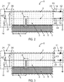
- FIGS. 2 and 3 schematically show a monitoring system 8 according to an embodiment of the invention is designed such that a filled with the transport medium 4 pipe R is automatically monitored and any occurring pipe break 9 is identified and located in a timely manner.
- the monitoring system 8 comprises a measuring device 10, which is connected via a second end 22 of the first measuring line 1 and a second end 23 of the second measuring line 2 to an end switch 11.
- the limit switch 11 includes two grounded blocking diodes 12, wherein in its first switch position 13, it connects the first measuring line 1 at its second end 22 to the second measuring line 2 at its second end 23 ( FIG. 3 ), and in its second switch position 14, the first measuring line 1 at its second end 22 and the second measuring line 2 at its second end 23 with one of the blocking diodes 12 connects ( FIG. 2 ).
- the limit switch 11 is in this case controlled by the measuring device 10 via the first measuring line 1 and / or the second measuring line 2.
- a corresponding detection is based on the fact that for determining the Pipe rupture 9 a threshold resistance at the first measuring line 1 and / or the second measuring line 2 is exceeded, and for detecting a wire break a threshold resistance on the measuring line 1 and / or the measuring line 2 is exceeded.
- the pipe break 9 is in this case detected insofar as due to damage of the plastic pipe 6 and / or the metal tube 5, moisture from the outside or from the inside enters the insulation material 3, and between the first measuring line 1 and / or the second measuring line 2 and grounded metal tube 5 forms an electrically conductive connection.
- the limit switch 11 is controlled to its first switch position 13, thereby connecting the first measuring line 1 to the second measuring line 2 at its second ends 22 and 23.
- the corresponding block diagram is in FIG. 3 shown.
- the pipe break 9 adjusting voltage divider From the measuring voltage 18 and the measuring voltage 20 is then on the pipe break 9 adjusting voltage divider, and with the aid of the lengths of the first measuring line 1, the second measuring line 2 and the metal tube 5, the location of the pipe crack 9, so the distance of the pipe crack 9 determined by the measuring device 10.
- This distance corresponds to the length component L of the measuring line 1 from its first end 19 to the location of the pipe break 9 and is proportional to the measuring voltage 18 that arises.
- the remaining length fraction from the location of the raw fracture 9 to the second end of the first measuring line 22, as well as the length of second measuring line 2 corresponds to the self-adjusting measuring voltage 20.
- the self-adjusting current can be, for example, 5 amperes.
- the accuracy of this distance location for determining the location of the pipe crack 9 is substantially three percent of the total length of the measuring lines used for the measurement.
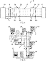
- FIG. 4 shows the monitoring system 8 according to a further embodiment, in which along the filled with the transport medium 4 pipe R in addition to the measuring device 10 and the Endumschalter 11 two intermediate changeover 24 are provided, which are also each controlled by the measuring device 10 and between a first switch position 25 and a second switch position 26 are switchable.
- each of the intermediate changeover switches 24 in the first switch position 25 connects all of the measuring lines coming from the measuring device 10 or another intermediate changeover switch 24 each with the Endumschalter 11, and includes in the second switch position 26 at least two, coming from the measuring device 10 or another intermediate switch 24 measuring lines short.
- FIG. 6 shows a further embodiment of the invention, wherein it allows the monitoring system 8 in the specific case of a district heating piping system 7, the first measuring line 1 and the second measuring line 2 of the pipes R of the supply lines as well as a third measuring line 27 and a fourth measuring line 28 of the pipes R of the derivatives fully automated and at selectable time intervals - for example, preferably 120 seconds - to monitor, and to use each of these test leads as a control means.
- any number of connection units 29, for example in each house can be installed, which permit the connection of a measuring device and / or at least two further measuring lines to at least two of the measuring lines 1 to 2 or 27 to 28 of the monitoring system 8.
- a portable measuring device such as a measuring case, respectively from both sides of the assumed location of the pipe crack 9, so for example, by the measuring device 10 and of the measuring device 10 closest to the connection unit 29, carried out a distance location.
- the respectively adjusting measuring voltages 18 correspond in each case to the length component L from the location of the rough fracture 9 to the portable measuring device. It is measured in each case in positive and negative polarity of the supply voltage 17.
- a positive polarity, or negative polarity, of the supply voltage 17 is present when the first end 19 of the first measuring line 1 is designed as a positive pole, or as a negative pole, and the first end 21 of the second measuring line 2 as a negative pole, or as a positive pole.
- a voltage U1 + With a positive polarity, or negative polarity, of the supply voltage 17, a voltage U1 + , or a voltage U1 - , is established between the first end 19 of the first measuring line 1 and the metal tube 5.
- the voltage U1 + or the voltage U1 - , thus corresponds to the measuring voltage 18 at positive polarity, or negative polarity, the supply voltage 17.
- measuring voltage 18 (U1 + + U1 - ) / 2 is an "external voltage correction" of the measuring voltage 18 performed.
- a "Fehlerwiderstandskorrektur" of each adjusting measuring voltages 18 is carried out with respect to the internal resistance of the pipeline.
- the monitoring system according to the invention can also be used for monitoring other pipelines.
- piping of a cooling system or even an oil or gas line could be monitored.
Landscapes
- Physics & Mathematics (AREA)
- General Physics & Mathematics (AREA)
- Pipeline Systems (AREA)
- Measuring Volume Flow (AREA)
Priority Applications (2)
| Application Number | Priority Date | Filing Date | Title |
|---|---|---|---|
| PL16165031T PL3101403T3 (pl) | 2015-04-24 | 2016-04-13 | Układ monitorowania do wykrywania uszkodzeń w rurociągach |
| SI201630012T SI3101403T1 (en) | 2015-04-24 | 2016-04-13 | Control system for identifying faulty pipeline locations |
Applications Claiming Priority (1)
| Application Number | Priority Date | Filing Date | Title |
|---|---|---|---|
| ATGM50072/2015U AT14914U1 (de) | 2015-04-24 | 2015-04-24 | Überwachungssystem zum Feststellen von Fehlerstellen in Rohrleitungen |
Publications (2)
| Publication Number | Publication Date |
|---|---|
| EP3101403A1 EP3101403A1 (de) | 2016-12-07 |
| EP3101403B1 true EP3101403B1 (de) | 2017-09-13 |
Family
ID=56564978
Family Applications (1)
| Application Number | Title | Priority Date | Filing Date |
|---|---|---|---|
| EP16165031.2A Active EP3101403B1 (de) | 2015-04-24 | 2016-04-13 | Überwachungssystem zum feststellen von fehlerstellen in rohrleitungen |
Country Status (5)
| Country | Link |
|---|---|
| EP (1) | EP3101403B1 (pl) |
| AT (1) | AT14914U1 (pl) |
| HU (1) | HUE035161T2 (pl) |
| PL (1) | PL3101403T3 (pl) |
| SI (1) | SI3101403T1 (pl) |
Families Citing this family (2)
| Publication number | Priority date | Publication date | Assignee | Title |
|---|---|---|---|---|
| WO2022224221A1 (en) * | 2021-04-23 | 2022-10-27 | Danfoss Power Solutions Ii Technology A/S | Hose sensor assembly including direct sensor integration integration with monitoring circuitry |
| AT18529U1 (de) * | 2025-02-20 | 2025-09-15 | Wundara Gmbh | Überwachungssystem zum Feststellen von Fehlerstellen in Rohrleitungen |
Family Cites Families (5)
| Publication number | Priority date | Publication date | Assignee | Title |
|---|---|---|---|---|
| AT388430B (de) * | 1987-05-06 | 1989-06-26 | Scheuermann Herbert Dipl Ing | Vorrichtung zur feststellung und ortung von leckstellen in einer ein feuchtes medium fuehrenden rohrleitung |
| EP0417061B1 (de) * | 1989-09-05 | 1994-03-02 | Brandes, Bernd | Verfahren und Vorrichtung zur Ortung des wahren Ortes einer Leckstelle in einer ein feuchtes Medium führenden Rohrleitung |
| DE4003788A1 (de) * | 1990-02-08 | 1991-08-14 | Salzgitter Elektronik Gmbh | Verfahren und vorrichtung zur ueberwachung einer zweidrahtleitung |
| DE19908056A1 (de) * | 1999-02-25 | 2000-08-31 | Curt Reichert | Leckstellenbestimmungsverfahren |
| KR20090116035A (ko) * | 2008-05-06 | 2009-11-11 | 최준수 | 키패드용 회전축을 이용한 다중키 버튼구조 |
-
2015
- 2015-04-24 AT ATGM50072/2015U patent/AT14914U1/de not_active IP Right Cessation
-
2016
- 2016-04-13 PL PL16165031T patent/PL3101403T3/pl unknown
- 2016-04-13 EP EP16165031.2A patent/EP3101403B1/de active Active
- 2016-04-13 SI SI201630012T patent/SI3101403T1/en unknown
- 2016-04-13 HU HUE16165031A patent/HUE035161T2/en unknown
Non-Patent Citations (1)
| Title |
|---|
| None * |
Also Published As
| Publication number | Publication date |
|---|---|
| EP3101403A1 (de) | 2016-12-07 |
| HUE035161T2 (en) | 2018-05-02 |
| SI3101403T1 (en) | 2018-01-31 |
| AT14914U1 (de) | 2016-08-15 |
| PL3101403T3 (pl) | 2018-02-28 |
Similar Documents
| Publication | Publication Date | Title |
|---|---|---|
| EP2669694B1 (de) | Verfahren und Vorrichtung zum Lokalisieren eines Kabelfehlers eines verlegten Kabels | |
| DE3930530C2 (pl) | ||
| EP0533960A1 (de) | Einrichtung und Verfahren zur Ermittlung von Undichtigkeiten an doppelwandigen Leitungsrohren für flüssige Medien | |
| DE102012019996A1 (de) | Leitungsnetz, insbesondere Gleichspannungs-Bordnetz für ein Kraftfahrzeug sowie Verfahren zur Überwachung eines Leitungsnetzes auf das Entstehen eines Lichtbogens | |
| EP0060552B1 (de) | Anordnung zur Überwachung eines Rohrleitungssystems, insbesondere aus wärmegedämmten Fernwärmerohren | |
| EP2112491B1 (de) | Vorrichtung, System und Verfahren zur Detektion und Ortung von Undichtigkeiten | |
| EP3492188B1 (de) | Vorrichtung mit verschleissteil und messeinrichtung für verschleiss | |
| DE2337983C2 (de) | Ortungs- und Überwachungsschaltung | |
| EP2988139A1 (de) | Überwachungssystem für ein stromkabel, stromkabel für ein solches überwachungssystem sowie verfahren zur überwachung eines stromkabels mit hilfe eines solchen überwachungssystems | |
| EP3872503A1 (de) | Überwachungsvorrichtung und verfahren zur isolationsüberwachung eines ungeerdeten elektrischen systems mit geerdet betriebener flüssigkeitskühlung | |
| EP3247984B1 (de) | Vorrichtung und verfahren zur temperaturerfassung sowie verwendung der vorrichtung | |
| DE19519650C2 (de) | Verfahren zur Ortung undichter Stellen in Rohrleitungen und Rohrleitungssystem, insbesondere für die Übertragung von Fernwärme | |
| EP3101403A1 (de) | Überwachungssystem zum feststellen von fehlerstellen in rohrleitungen | |
| WO2019154584A1 (de) | Verfahren zur vorhersage einer bevorstehenden beschädigung einer verbindungsstelle zwischen zwei elektrischen leitern in einem kraftfahrzeugbordnetz, vorrichtung und kraftfahrzeug | |
| AT511991B1 (de) | Verfahren und einrichtung zum versorgen wenigstens eines elektrischen verbrauchers eines bohrgestänges mit einer betriebsspannung | |
| EP3776780A1 (de) | Verfahren und vorrichtung zur erkennung eines windungsschlusses bei parallel angeordneten wicklungen | |
| AT18529U1 (de) | Überwachungssystem zum Feststellen von Fehlerstellen in Rohrleitungen | |
| WO2016142205A1 (de) | VERFAHREN ZUR ZUSTANDSBESTIMMUNG UND FEHLERORTUNG AN INSTALLIERTEN ISOLIERTEN ABLEITUNGEN IM ÄUßEREN BLITZSCHUTZ | |
| WO2010000247A2 (de) | Verfahren und vorrichtung zur messung der temperatur in einer leitung oder einem leitungsbündel und mit einer solchen vorrichtung ausgerüstetes fahrzeug | |
| DE102014219537A1 (de) | Verfahren und Anordnung für die Ermittlung eines Fehlerortes bei einem Kurzschluss entlang einer Energieversorgungsstrecke | |
| EP3336508A1 (de) | Zählereinrichtung, zählersystem und verfahren zum betrieb einer zählereinrichtung | |
| AT528102B1 (de) | System und Verfahren zum Überwachen von Teilentladungsaktivität | |
| EP1728895A1 (de) | Ein Überwachungsverfahren zum Feststellen einer Annäherung eines leitfähigen Körpers an eine mit einem kathodischen Schutzstrom beaufschlagte Fluid-Transportpipeline | |
| DE202008006899U1 (de) | Vorrichtung zum Detektieren von Temperaturen in Bereichen einer technischen Anlage | |
| DE102018133423A1 (de) | Proportionale Erkennung des Verschleißgrades von Stromabnehmern |
Legal Events
| Date | Code | Title | Description |
|---|---|---|---|
| PUAI | Public reference made under article 153(3) epc to a published international application that has entered the european phase |
Free format text: ORIGINAL CODE: 0009012 |
|
| STAA | Information on the status of an ep patent application or granted ep patent |
Free format text: STATUS: THE APPLICATION HAS BEEN PUBLISHED |
|
| AK | Designated contracting states |
Kind code of ref document: A1 Designated state(s): AL AT BE BG CH CY CZ DE DK EE ES FI FR GB GR HR HU IE IS IT LI LT LU LV MC MK MT NL NO PL PT RO RS SE SI SK SM TR |
|
| AX | Request for extension of the european patent |
Extension state: BA ME |
|
| STAA | Information on the status of an ep patent application or granted ep patent |
Free format text: STATUS: REQUEST FOR EXAMINATION WAS MADE |
|
| 17P | Request for examination filed |
Effective date: 20161230 |
|
| RBV | Designated contracting states (corrected) |
Designated state(s): AL AT BE BG CH CY CZ DE DK EE ES FI FR GB GR HR HU IE IS IT LI LT LU LV MC MK MT NL NO PL PT RO RS SE SI SK SM TR |
|
| GRAP | Despatch of communication of intention to grant a patent |
Free format text: ORIGINAL CODE: EPIDOSNIGR1 |
|
| STAA | Information on the status of an ep patent application or granted ep patent |
Free format text: STATUS: GRANT OF PATENT IS INTENDED |
|
| RIC1 | Information provided on ipc code assigned before grant |
Ipc: G01M 3/16 20060101AFI20170221BHEP Ipc: F16L 59/14 20060101ALI20170221BHEP Ipc: G01M 3/18 20060101ALI20170221BHEP |
|
| INTG | Intention to grant announced |
Effective date: 20170328 |
|
| GRAS | Grant fee paid |
Free format text: ORIGINAL CODE: EPIDOSNIGR3 |
|
| GRAA | (expected) grant |
Free format text: ORIGINAL CODE: 0009210 |
|
| STAA | Information on the status of an ep patent application or granted ep patent |
Free format text: STATUS: THE PATENT HAS BEEN GRANTED |
|
| AK | Designated contracting states |
Kind code of ref document: B1 Designated state(s): AL AT BE BG CH CY CZ DE DK EE ES FI FR GB GR HR HU IE IS IT LI LT LU LV MC MK MT NL NO PL PT RO RS SE SI SK SM TR |
|
| REG | Reference to a national code |
Ref country code: GB Ref legal event code: FG4D Free format text: NOT ENGLISH |
|
| REG | Reference to a national code |
Ref country code: CH Ref legal event code: EP |
|
| REG | Reference to a national code |
Ref country code: IE Ref legal event code: FG4D Free format text: LANGUAGE OF EP DOCUMENT: GERMAN |
|
| REG | Reference to a national code |
Ref country code: AT Ref legal event code: REF Ref document number: 928628 Country of ref document: AT Kind code of ref document: T Effective date: 20171015 |
|
| REG | Reference to a national code |
Ref country code: DE Ref legal event code: R096 Ref document number: 502016000133 Country of ref document: DE |
|
| REG | Reference to a national code |
Ref country code: CH Ref legal event code: NV Representative=s name: BOHEST AG, CH |
|
| REG | Reference to a national code |
Ref country code: NL Ref legal event code: MP Effective date: 20170913 |
|
| REG | Reference to a national code |
Ref country code: LT Ref legal event code: MG4D |
|
| PG25 | Lapsed in a contracting state [announced via postgrant information from national office to epo] |
Ref country code: HR Free format text: LAPSE BECAUSE OF FAILURE TO SUBMIT A TRANSLATION OF THE DESCRIPTION OR TO PAY THE FEE WITHIN THE PRESCRIBED TIME-LIMIT Effective date: 20170913 Ref country code: LT Free format text: LAPSE BECAUSE OF FAILURE TO SUBMIT A TRANSLATION OF THE DESCRIPTION OR TO PAY THE FEE WITHIN THE PRESCRIBED TIME-LIMIT Effective date: 20170913 Ref country code: SE Free format text: LAPSE BECAUSE OF FAILURE TO SUBMIT A TRANSLATION OF THE DESCRIPTION OR TO PAY THE FEE WITHIN THE PRESCRIBED TIME-LIMIT Effective date: 20170913 Ref country code: FI Free format text: LAPSE BECAUSE OF FAILURE TO SUBMIT A TRANSLATION OF THE DESCRIPTION OR TO PAY THE FEE WITHIN THE PRESCRIBED TIME-LIMIT Effective date: 20170913 Ref country code: NO Free format text: LAPSE BECAUSE OF FAILURE TO SUBMIT A TRANSLATION OF THE DESCRIPTION OR TO PAY THE FEE WITHIN THE PRESCRIBED TIME-LIMIT Effective date: 20171213 |
|
| PG25 | Lapsed in a contracting state [announced via postgrant information from national office to epo] |
Ref country code: GR Free format text: LAPSE BECAUSE OF FAILURE TO SUBMIT A TRANSLATION OF THE DESCRIPTION OR TO PAY THE FEE WITHIN THE PRESCRIBED TIME-LIMIT Effective date: 20171214 Ref country code: ES Free format text: LAPSE BECAUSE OF FAILURE TO SUBMIT A TRANSLATION OF THE DESCRIPTION OR TO PAY THE FEE WITHIN THE PRESCRIBED TIME-LIMIT Effective date: 20170913 Ref country code: BG Free format text: LAPSE BECAUSE OF FAILURE TO SUBMIT A TRANSLATION OF THE DESCRIPTION OR TO PAY THE FEE WITHIN THE PRESCRIBED TIME-LIMIT Effective date: 20171213 Ref country code: LV Free format text: LAPSE BECAUSE OF FAILURE TO SUBMIT A TRANSLATION OF THE DESCRIPTION OR TO PAY THE FEE WITHIN THE PRESCRIBED TIME-LIMIT Effective date: 20170913 Ref country code: RS Free format text: LAPSE BECAUSE OF FAILURE TO SUBMIT A TRANSLATION OF THE DESCRIPTION OR TO PAY THE FEE WITHIN THE PRESCRIBED TIME-LIMIT Effective date: 20170913 |
|
| PG25 | Lapsed in a contracting state [announced via postgrant information from national office to epo] |
Ref country code: NL Free format text: LAPSE BECAUSE OF FAILURE TO SUBMIT A TRANSLATION OF THE DESCRIPTION OR TO PAY THE FEE WITHIN THE PRESCRIBED TIME-LIMIT Effective date: 20170913 |
|
| REG | Reference to a national code |
Ref country code: FR Ref legal event code: PLFP Year of fee payment: 3 |
|
| PG25 | Lapsed in a contracting state [announced via postgrant information from national office to epo] |
Ref country code: CZ Free format text: LAPSE BECAUSE OF FAILURE TO SUBMIT A TRANSLATION OF THE DESCRIPTION OR TO PAY THE FEE WITHIN THE PRESCRIBED TIME-LIMIT Effective date: 20170913 |
|
| REG | Reference to a national code |
Ref country code: HU Ref legal event code: AG4A Ref document number: E035161 Country of ref document: HU |
|
| PG25 | Lapsed in a contracting state [announced via postgrant information from national office to epo] |
Ref country code: SM Free format text: LAPSE BECAUSE OF FAILURE TO SUBMIT A TRANSLATION OF THE DESCRIPTION OR TO PAY THE FEE WITHIN THE PRESCRIBED TIME-LIMIT Effective date: 20170913 Ref country code: IS Free format text: LAPSE BECAUSE OF FAILURE TO SUBMIT A TRANSLATION OF THE DESCRIPTION OR TO PAY THE FEE WITHIN THE PRESCRIBED TIME-LIMIT Effective date: 20180113 Ref country code: SK Free format text: LAPSE BECAUSE OF FAILURE TO SUBMIT A TRANSLATION OF THE DESCRIPTION OR TO PAY THE FEE WITHIN THE PRESCRIBED TIME-LIMIT Effective date: 20170913 Ref country code: EE Free format text: LAPSE BECAUSE OF FAILURE TO SUBMIT A TRANSLATION OF THE DESCRIPTION OR TO PAY THE FEE WITHIN THE PRESCRIBED TIME-LIMIT Effective date: 20170913 |
|
| REG | Reference to a national code |
Ref country code: DE Ref legal event code: R097 Ref document number: 502016000133 Country of ref document: DE |
|
| PLBE | No opposition filed within time limit |
Free format text: ORIGINAL CODE: 0009261 |
|
| STAA | Information on the status of an ep patent application or granted ep patent |
Free format text: STATUS: NO OPPOSITION FILED WITHIN TIME LIMIT |
|
| PG25 | Lapsed in a contracting state [announced via postgrant information from national office to epo] |
Ref country code: DK Free format text: LAPSE BECAUSE OF FAILURE TO SUBMIT A TRANSLATION OF THE DESCRIPTION OR TO PAY THE FEE WITHIN THE PRESCRIBED TIME-LIMIT Effective date: 20170913 |
|
| 26N | No opposition filed |
Effective date: 20180614 |
|
| PG25 | Lapsed in a contracting state [announced via postgrant information from national office to epo] |
Ref country code: MT Free format text: LAPSE BECAUSE OF FAILURE TO SUBMIT A TRANSLATION OF THE DESCRIPTION OR TO PAY THE FEE WITHIN THE PRESCRIBED TIME-LIMIT Effective date: 20170913 |
|
| PG25 | Lapsed in a contracting state [announced via postgrant information from national office to epo] |
Ref country code: MC Free format text: LAPSE BECAUSE OF FAILURE TO SUBMIT A TRANSLATION OF THE DESCRIPTION OR TO PAY THE FEE WITHIN THE PRESCRIBED TIME-LIMIT Effective date: 20170913 |
|
| REG | Reference to a national code |
Ref country code: BE Ref legal event code: MM Effective date: 20180430 |
|
| REG | Reference to a national code |
Ref country code: IE Ref legal event code: MM4A |
|
| PG25 | Lapsed in a contracting state [announced via postgrant information from national office to epo] |
Ref country code: LU Free format text: LAPSE BECAUSE OF NON-PAYMENT OF DUE FEES Effective date: 20180413 |
|
| PG25 | Lapsed in a contracting state [announced via postgrant information from national office to epo] |
Ref country code: BE Free format text: LAPSE BECAUSE OF NON-PAYMENT OF DUE FEES Effective date: 20180430 |
|
| PG25 | Lapsed in a contracting state [announced via postgrant information from national office to epo] |
Ref country code: IE Free format text: LAPSE BECAUSE OF NON-PAYMENT OF DUE FEES Effective date: 20180413 |
|
| PG25 | Lapsed in a contracting state [announced via postgrant information from national office to epo] |
Ref country code: TR Free format text: LAPSE BECAUSE OF FAILURE TO SUBMIT A TRANSLATION OF THE DESCRIPTION OR TO PAY THE FEE WITHIN THE PRESCRIBED TIME-LIMIT Effective date: 20170913 |
|
| PG25 | Lapsed in a contracting state [announced via postgrant information from national office to epo] |
Ref country code: PT Free format text: LAPSE BECAUSE OF FAILURE TO SUBMIT A TRANSLATION OF THE DESCRIPTION OR TO PAY THE FEE WITHIN THE PRESCRIBED TIME-LIMIT Effective date: 20170913 |
|
| PG25 | Lapsed in a contracting state [announced via postgrant information from national office to epo] |
Ref country code: RO Free format text: LAPSE BECAUSE OF FAILURE TO SUBMIT A TRANSLATION OF THE DESCRIPTION OR TO PAY THE FEE WITHIN THE PRESCRIBED TIME-LIMIT Effective date: 20170913 Ref country code: MK Free format text: LAPSE BECAUSE OF NON-PAYMENT OF DUE FEES Effective date: 20170913 Ref country code: CY Free format text: LAPSE BECAUSE OF FAILURE TO SUBMIT A TRANSLATION OF THE DESCRIPTION OR TO PAY THE FEE WITHIN THE PRESCRIBED TIME-LIMIT Effective date: 20170913 |
|
| PG25 | Lapsed in a contracting state [announced via postgrant information from national office to epo] |
Ref country code: AL Free format text: LAPSE BECAUSE OF FAILURE TO SUBMIT A TRANSLATION OF THE DESCRIPTION OR TO PAY THE FEE WITHIN THE PRESCRIBED TIME-LIMIT Effective date: 20170913 |
|
| GBPC | Gb: european patent ceased through non-payment of renewal fee |
Effective date: 20200413 |
|
| PG25 | Lapsed in a contracting state [announced via postgrant information from national office to epo] |
Ref country code: GB Free format text: LAPSE BECAUSE OF NON-PAYMENT OF DUE FEES Effective date: 20200413 |
|
| REG | Reference to a national code |
Ref country code: AT Ref legal event code: MM01 Ref document number: 928628 Country of ref document: AT Kind code of ref document: T Effective date: 20210413 |
|
| PG25 | Lapsed in a contracting state [announced via postgrant information from national office to epo] |
Ref country code: AT Free format text: LAPSE BECAUSE OF NON-PAYMENT OF DUE FEES Effective date: 20210413 |
|
| PGFP | Annual fee paid to national office [announced via postgrant information from national office to epo] |
Ref country code: SI Payment date: 20250401 Year of fee payment: 10 |
|
| PGFP | Annual fee paid to national office [announced via postgrant information from national office to epo] |
Ref country code: PL Payment date: 20250404 Year of fee payment: 10 Ref country code: DE Payment date: 20250417 Year of fee payment: 10 |
|
| PGFP | Annual fee paid to national office [announced via postgrant information from national office to epo] |
Ref country code: HU Payment date: 20250404 Year of fee payment: 10 |
|
| PGFP | Annual fee paid to national office [announced via postgrant information from national office to epo] |
Ref country code: IT Payment date: 20250430 Year of fee payment: 10 |
|
| PGFP | Annual fee paid to national office [announced via postgrant information from national office to epo] |
Ref country code: FR Payment date: 20250422 Year of fee payment: 10 |
|
| PGFP | Annual fee paid to national office [announced via postgrant information from national office to epo] |
Ref country code: CH Payment date: 20250501 Year of fee payment: 10 |
|
| REG | Reference to a national code |
Ref country code: CH Ref legal event code: U11 Free format text: ST27 STATUS EVENT CODE: U-0-0-U10-U11 (AS PROVIDED BY THE NATIONAL OFFICE) Effective date: 20260501 |