EP3101255A1 - Betriebsverfahren für eine abgasreinigungsanlage und entsprechendes antriebssystem - Google Patents
Betriebsverfahren für eine abgasreinigungsanlage und entsprechendes antriebssystem Download PDFInfo
- Publication number
- EP3101255A1 EP3101255A1 EP16001015.3A EP16001015A EP3101255A1 EP 3101255 A1 EP3101255 A1 EP 3101255A1 EP 16001015 A EP16001015 A EP 16001015A EP 3101255 A1 EP3101255 A1 EP 3101255A1
- Authority
- EP
- European Patent Office
- Prior art keywords
- catalytic converter
- engine
- cleaning effect
- internal combustion
- combustion engine
- Prior art date
- Legal status (The legal status is an assumption and is not a legal conclusion. Google has not performed a legal analysis and makes no representation as to the accuracy of the status listed.)
- Granted
Links
Images


Classifications
-
- F—MECHANICAL ENGINEERING; LIGHTING; HEATING; WEAPONS; BLASTING
- F01—MACHINES OR ENGINES IN GENERAL; ENGINE PLANTS IN GENERAL; STEAM ENGINES
- F01N—GAS-FLOW SILENCERS OR EXHAUST APPARATUS FOR MACHINES OR ENGINES IN GENERAL; GAS-FLOW SILENCERS OR EXHAUST APPARATUS FOR INTERNAL-COMBUSTION ENGINES
- F01N3/00—Exhaust or silencing apparatus having means for purifying, rendering innocuous, or otherwise treating exhaust
- F01N3/08—Exhaust or silencing apparatus having means for purifying, rendering innocuous, or otherwise treating exhaust for rendering innocuous
- F01N3/10—Exhaust or silencing apparatus having means for purifying, rendering innocuous, or otherwise treating exhaust for rendering innocuous by thermal or catalytic conversion of noxious components of exhaust
- F01N3/101—Three-way catalysts
-
- F—MECHANICAL ENGINEERING; LIGHTING; HEATING; WEAPONS; BLASTING
- F01—MACHINES OR ENGINES IN GENERAL; ENGINE PLANTS IN GENERAL; STEAM ENGINES
- F01N—GAS-FLOW SILENCERS OR EXHAUST APPARATUS FOR MACHINES OR ENGINES IN GENERAL; GAS-FLOW SILENCERS OR EXHAUST APPARATUS FOR INTERNAL-COMBUSTION ENGINES
- F01N11/00—Monitoring or diagnostic devices for exhaust-gas treatment apparatus
-
- F—MECHANICAL ENGINEERING; LIGHTING; HEATING; WEAPONS; BLASTING
- F01—MACHINES OR ENGINES IN GENERAL; ENGINE PLANTS IN GENERAL; STEAM ENGINES
- F01N—GAS-FLOW SILENCERS OR EXHAUST APPARATUS FOR MACHINES OR ENGINES IN GENERAL; GAS-FLOW SILENCERS OR EXHAUST APPARATUS FOR INTERNAL-COMBUSTION ENGINES
- F01N3/00—Exhaust or silencing apparatus having means for purifying, rendering innocuous, or otherwise treating exhaust
- F01N3/08—Exhaust or silencing apparatus having means for purifying, rendering innocuous, or otherwise treating exhaust for rendering innocuous
- F01N3/10—Exhaust or silencing apparatus having means for purifying, rendering innocuous, or otherwise treating exhaust for rendering innocuous by thermal or catalytic conversion of noxious components of exhaust
- F01N3/18—Exhaust or silencing apparatus having means for purifying, rendering innocuous, or otherwise treating exhaust for rendering innocuous by thermal or catalytic conversion of noxious components of exhaust characterised by methods of operation; Control
- F01N3/20—Exhaust or silencing apparatus having means for purifying, rendering innocuous, or otherwise treating exhaust for rendering innocuous by thermal or catalytic conversion of noxious components of exhaust characterised by methods of operation; Control specially adapted for catalytic conversion
-
- F—MECHANICAL ENGINEERING; LIGHTING; HEATING; WEAPONS; BLASTING
- F01—MACHINES OR ENGINES IN GENERAL; ENGINE PLANTS IN GENERAL; STEAM ENGINES
- F01N—GAS-FLOW SILENCERS OR EXHAUST APPARATUS FOR MACHINES OR ENGINES IN GENERAL; GAS-FLOW SILENCERS OR EXHAUST APPARATUS FOR INTERNAL-COMBUSTION ENGINES
- F01N9/00—Electrical control of exhaust gas treating apparatus
-
- F—MECHANICAL ENGINEERING; LIGHTING; HEATING; WEAPONS; BLASTING
- F02—COMBUSTION ENGINES; HOT-GAS OR COMBUSTION-PRODUCT ENGINE PLANTS
- F02D—CONTROLLING COMBUSTION ENGINES
- F02D37/00—Non-electrical conjoint control of two or more functions of engines, not otherwise provided for
- F02D37/02—Non-electrical conjoint control of two or more functions of engines, not otherwise provided for one of the functions being ignition
-
- F—MECHANICAL ENGINEERING; LIGHTING; HEATING; WEAPONS; BLASTING
- F02—COMBUSTION ENGINES; HOT-GAS OR COMBUSTION-PRODUCT ENGINE PLANTS
- F02D—CONTROLLING COMBUSTION ENGINES
- F02D41/00—Electrical control of supply of combustible mixture or its constituents
- F02D41/02—Circuit arrangements for generating control signals
- F02D41/021—Introducing corrections for particular conditions exterior to the engine
- F02D41/0235—Introducing corrections for particular conditions exterior to the engine in relation with the state of the exhaust gas treating apparatus
-
- F—MECHANICAL ENGINEERING; LIGHTING; HEATING; WEAPONS; BLASTING
- F02—COMBUSTION ENGINES; HOT-GAS OR COMBUSTION-PRODUCT ENGINE PLANTS
- F02D—CONTROLLING COMBUSTION ENGINES
- F02D41/00—Electrical control of supply of combustible mixture or its constituents
- F02D41/02—Circuit arrangements for generating control signals
- F02D41/021—Introducing corrections for particular conditions exterior to the engine
- F02D41/0235—Introducing corrections for particular conditions exterior to the engine in relation with the state of the exhaust gas treating apparatus
- F02D41/024—Introducing corrections for particular conditions exterior to the engine in relation with the state of the exhaust gas treating apparatus to increase temperature of the exhaust gas treating apparatus
-
- F—MECHANICAL ENGINEERING; LIGHTING; HEATING; WEAPONS; BLASTING
- F02—COMBUSTION ENGINES; HOT-GAS OR COMBUSTION-PRODUCT ENGINE PLANTS
- F02D—CONTROLLING COMBUSTION ENGINES
- F02D41/00—Electrical control of supply of combustible mixture or its constituents
- F02D41/02—Circuit arrangements for generating control signals
- F02D41/14—Introducing closed-loop corrections
- F02D41/1438—Introducing closed-loop corrections using means for determining characteristics of the combustion gases; Sensors therefor
- F02D41/1444—Introducing closed-loop corrections using means for determining characteristics of the combustion gases; Sensors therefor characterised by the characteristics of the combustion gases
- F02D41/1454—Introducing closed-loop corrections using means for determining characteristics of the combustion gases; Sensors therefor characterised by the characteristics of the combustion gases the characteristics being an oxygen content or concentration or the air-fuel ratio
- F02D41/1456—Introducing closed-loop corrections using means for determining characteristics of the combustion gases; Sensors therefor characterised by the characteristics of the combustion gases the characteristics being an oxygen content or concentration or the air-fuel ratio with sensor output signal being linear or quasi-linear with the concentration of oxygen
-
- F—MECHANICAL ENGINEERING; LIGHTING; HEATING; WEAPONS; BLASTING
- F02—COMBUSTION ENGINES; HOT-GAS OR COMBUSTION-PRODUCT ENGINE PLANTS
- F02D—CONTROLLING COMBUSTION ENGINES
- F02D41/00—Electrical control of supply of combustible mixture or its constituents
- F02D41/24—Electrical control of supply of combustible mixture or its constituents characterised by the use of digital means
- F02D41/2406—Electrical control of supply of combustible mixture or its constituents characterised by the use of digital means using essentially read only memories
- F02D41/2425—Particular ways of programming the data
- F02D41/2429—Methods of calibrating or learning
- F02D41/2451—Methods of calibrating or learning characterised by what is learned or calibrated
-
- F—MECHANICAL ENGINEERING; LIGHTING; HEATING; WEAPONS; BLASTING
- F01—MACHINES OR ENGINES IN GENERAL; ENGINE PLANTS IN GENERAL; STEAM ENGINES
- F01N—GAS-FLOW SILENCERS OR EXHAUST APPARATUS FOR MACHINES OR ENGINES IN GENERAL; GAS-FLOW SILENCERS OR EXHAUST APPARATUS FOR INTERNAL-COMBUSTION ENGINES
- F01N2430/00—Influencing exhaust purification, e.g. starting of catalytic reaction, filter regeneration, or the like, by controlling engine operating characteristics
- F01N2430/04—Influencing exhaust purification, e.g. starting of catalytic reaction, filter regeneration, or the like, by controlling engine operating characteristics by adding non-fuel substances to combustion air or fuel, e.g. additives
-
- F—MECHANICAL ENGINEERING; LIGHTING; HEATING; WEAPONS; BLASTING
- F01—MACHINES OR ENGINES IN GENERAL; ENGINE PLANTS IN GENERAL; STEAM ENGINES
- F01N—GAS-FLOW SILENCERS OR EXHAUST APPARATUS FOR MACHINES OR ENGINES IN GENERAL; GAS-FLOW SILENCERS OR EXHAUST APPARATUS FOR INTERNAL-COMBUSTION ENGINES
- F01N2430/00—Influencing exhaust purification, e.g. starting of catalytic reaction, filter regeneration, or the like, by controlling engine operating characteristics
- F01N2430/08—Influencing exhaust purification, e.g. starting of catalytic reaction, filter regeneration, or the like, by controlling engine operating characteristics by modifying ignition or injection timing
-
- F—MECHANICAL ENGINEERING; LIGHTING; HEATING; WEAPONS; BLASTING
- F01—MACHINES OR ENGINES IN GENERAL; ENGINE PLANTS IN GENERAL; STEAM ENGINES
- F01N—GAS-FLOW SILENCERS OR EXHAUST APPARATUS FOR MACHINES OR ENGINES IN GENERAL; GAS-FLOW SILENCERS OR EXHAUST APPARATUS FOR INTERNAL-COMBUSTION ENGINES
- F01N2900/00—Details of electrical control or of the monitoring of the exhaust gas treating apparatus
- F01N2900/04—Methods of control or diagnosing
- F01N2900/0416—Methods of control or diagnosing using the state of a sensor, e.g. of an exhaust gas sensor
-
- F—MECHANICAL ENGINEERING; LIGHTING; HEATING; WEAPONS; BLASTING
- F01—MACHINES OR ENGINES IN GENERAL; ENGINE PLANTS IN GENERAL; STEAM ENGINES
- F01N—GAS-FLOW SILENCERS OR EXHAUST APPARATUS FOR MACHINES OR ENGINES IN GENERAL; GAS-FLOW SILENCERS OR EXHAUST APPARATUS FOR INTERNAL-COMBUSTION ENGINES
- F01N2900/00—Details of electrical control or of the monitoring of the exhaust gas treating apparatus
- F01N2900/06—Parameters used for exhaust control or diagnosing
- F01N2900/08—Parameters used for exhaust control or diagnosing said parameters being related to the engine
-
- F—MECHANICAL ENGINEERING; LIGHTING; HEATING; WEAPONS; BLASTING
- F01—MACHINES OR ENGINES IN GENERAL; ENGINE PLANTS IN GENERAL; STEAM ENGINES
- F01N—GAS-FLOW SILENCERS OR EXHAUST APPARATUS FOR MACHINES OR ENGINES IN GENERAL; GAS-FLOW SILENCERS OR EXHAUST APPARATUS FOR INTERNAL-COMBUSTION ENGINES
- F01N2900/00—Details of electrical control or of the monitoring of the exhaust gas treating apparatus
- F01N2900/06—Parameters used for exhaust control or diagnosing
- F01N2900/16—Parameters used for exhaust control or diagnosing said parameters being related to the exhaust apparatus, e.g. particulate filter or catalyst
- F01N2900/1602—Temperature of exhaust gas apparatus
-
- F—MECHANICAL ENGINEERING; LIGHTING; HEATING; WEAPONS; BLASTING
- F01—MACHINES OR ENGINES IN GENERAL; ENGINE PLANTS IN GENERAL; STEAM ENGINES
- F01N—GAS-FLOW SILENCERS OR EXHAUST APPARATUS FOR MACHINES OR ENGINES IN GENERAL; GAS-FLOW SILENCERS OR EXHAUST APPARATUS FOR INTERNAL-COMBUSTION ENGINES
- F01N2900/00—Details of electrical control or of the monitoring of the exhaust gas treating apparatus
- F01N2900/06—Parameters used for exhaust control or diagnosing
- F01N2900/16—Parameters used for exhaust control or diagnosing said parameters being related to the exhaust apparatus, e.g. particulate filter or catalyst
- F01N2900/1624—Catalyst oxygen storage capacity
-
- F—MECHANICAL ENGINEERING; LIGHTING; HEATING; WEAPONS; BLASTING
- F02—COMBUSTION ENGINES; HOT-GAS OR COMBUSTION-PRODUCT ENGINE PLANTS
- F02D—CONTROLLING COMBUSTION ENGINES
- F02D2200/00—Input parameters for engine control
- F02D2200/02—Input parameters for engine control the parameters being related to the engine
- F02D2200/08—Exhaust gas treatment apparatus parameters
- F02D2200/0802—Temperature of the exhaust gas treatment apparatus
-
- F—MECHANICAL ENGINEERING; LIGHTING; HEATING; WEAPONS; BLASTING
- F02—COMBUSTION ENGINES; HOT-GAS OR COMBUSTION-PRODUCT ENGINE PLANTS
- F02D—CONTROLLING COMBUSTION ENGINES
- F02D2200/00—Input parameters for engine control
- F02D2200/02—Input parameters for engine control the parameters being related to the engine
- F02D2200/08—Exhaust gas treatment apparatus parameters
- F02D2200/0814—Oxygen storage amount
-
- F—MECHANICAL ENGINEERING; LIGHTING; HEATING; WEAPONS; BLASTING
- F02—COMBUSTION ENGINES; HOT-GAS OR COMBUSTION-PRODUCT ENGINE PLANTS
- F02D—CONTROLLING COMBUSTION ENGINES
- F02D2200/00—Input parameters for engine control
- F02D2200/02—Input parameters for engine control the parameters being related to the engine
- F02D2200/08—Exhaust gas treatment apparatus parameters
- F02D2200/0816—Oxygen storage capacity
-
- Y—GENERAL TAGGING OF NEW TECHNOLOGICAL DEVELOPMENTS; GENERAL TAGGING OF CROSS-SECTIONAL TECHNOLOGIES SPANNING OVER SEVERAL SECTIONS OF THE IPC; TECHNICAL SUBJECTS COVERED BY FORMER USPC CROSS-REFERENCE ART COLLECTIONS [XRACs] AND DIGESTS
- Y02—TECHNOLOGIES OR APPLICATIONS FOR MITIGATION OR ADAPTATION AGAINST CLIMATE CHANGE
- Y02A—TECHNOLOGIES FOR ADAPTATION TO CLIMATE CHANGE
- Y02A50/00—TECHNOLOGIES FOR ADAPTATION TO CLIMATE CHANGE in human health protection, e.g. against extreme weather
- Y02A50/20—Air quality improvement or preservation, e.g. vehicle emission control or emission reduction by using catalytic converters
-
- Y—GENERAL TAGGING OF NEW TECHNOLOGICAL DEVELOPMENTS; GENERAL TAGGING OF CROSS-SECTIONAL TECHNOLOGIES SPANNING OVER SEVERAL SECTIONS OF THE IPC; TECHNICAL SUBJECTS COVERED BY FORMER USPC CROSS-REFERENCE ART COLLECTIONS [XRACs] AND DIGESTS
- Y02—TECHNOLOGIES OR APPLICATIONS FOR MITIGATION OR ADAPTATION AGAINST CLIMATE CHANGE
- Y02T—CLIMATE CHANGE MITIGATION TECHNOLOGIES RELATED TO TRANSPORTATION
- Y02T10/00—Road transport of goods or passengers
- Y02T10/10—Internal combustion engine [ICE] based vehicles
- Y02T10/12—Improving ICE efficiencies
-
- Y—GENERAL TAGGING OF NEW TECHNOLOGICAL DEVELOPMENTS; GENERAL TAGGING OF CROSS-SECTIONAL TECHNOLOGIES SPANNING OVER SEVERAL SECTIONS OF THE IPC; TECHNICAL SUBJECTS COVERED BY FORMER USPC CROSS-REFERENCE ART COLLECTIONS [XRACs] AND DIGESTS
- Y02—TECHNOLOGIES OR APPLICATIONS FOR MITIGATION OR ADAPTATION AGAINST CLIMATE CHANGE
- Y02T—CLIMATE CHANGE MITIGATION TECHNOLOGIES RELATED TO TRANSPORTATION
- Y02T10/00—Road transport of goods or passengers
- Y02T10/10—Internal combustion engine [ICE] based vehicles
- Y02T10/40—Engine management systems
Definitions
- the invention relates to an operating method for an exhaust gas purification system having an exhaust gas catalytic converter (for example a three-way catalytic converter) for purifying exhaust gas in an internal combustion engine, in particular in a motor vehicle. Furthermore, the invention relates to a drive system, in particular for a motor vehicle with an internal combustion engine and an exhaust gas catalyst.
- an exhaust gas catalytic converter for example a three-way catalytic converter
- the oxygen storage capacity (OSC: O xygen S torage C apacity) of the exhaust gas catalyst As a measure of the catalyst state is usually the oxygen storage capacity (OSC: O xygen S torage C apacity) of the exhaust gas catalyst.
- OSC value oxygen storage capacity
- This OSC value is measured regularly in the on-board diagnostics anyway and is therefore available as a measured variable in the engine control unit. It is therefore known from the prior art to determine a catalyst parameter (OSC value) of the catalytic converter, which represents the cleaning effect of the exhaust gas catalytic converter. Furthermore, it is known from the prior art to carry out engine measures in dependence on the determined catalyst parameter of the exhaust gas catalytic converter (eg ignition angle adjustment) in order to improve the cleaning effect of the exhaust gas catalytic converter, if the determined catalyst parameter (OSC value) indicates an insufficient cleaning effect of the catalytic converter.
- OSC value oxygen storage capacity
- a disadvantage of this known method is the fact that the engine measures (eg, retardation of the ignition angle) result in increased fuel consumption and correspondingly increased CO 2 emissions in order to improve the cleaning effect of the exhaust gas catalytic converter. So there is a conflict of objectives between the
- the invention is therefore based on the object to solve this problem.
- the invention is based on the technical and physical knowledge that the increase in the "light-off temperature" associated with the aging of the catalytic converter is problematic only in parts of the engine map if the actual exhaust gas temperature does not increase the "light-off temperature" due to aging exceeds.
- the exhaust gas temperature in full-load operation (eg in a fast highway ride) is usually sufficiently large to exceed an age-related increased "light-off temperature", so that no motor measures are required in this operating point to improve the cleaning effect of the catalytic converter. Rather, such consumption-increasing motor measures should be omitted in such an operating point, since they are not required to improve the cleaning effect, but would increase fuel consumption and thus the CO 2 emissions.
- the engine measures (for example, ignition angle adjustment) for improving the cleaning effect of the catalytic converter are not only carried out as in the prior art as a function of the determined catalyst parameter (eg OSC value) but also depending on the operating point of the internal combustion engine.
- the engine measures for improving the cleaning effect of the catalytic converter are preferably carried out only if two conditions are met.
- the determined catalyst parameter (eg OSC value) indicate that the cleaning effect of the catalytic converter has dropped.
- the operating point of the internal combustion engine within the engine map must be in a range in which an improvement in the cleaning effect is currently required, so that then corresponding motor measures to improve the cleaning effect of the catalytic converter must be initiated. For example, in high-load operation at high exhaust gas temperatures usually no engine measures are required to improve the cleaning effect of the catalytic converter, whereas a partial load operation (eg in city traffic) with correspondingly low exhaust gas temperatures may make it necessary to improve the cleaning effect.
- the implementation of the engine measures (eg ignition angle adjustment) to improve the cleaning effect of the catalytic converter depends not only qualitatively on the current operating point of the internal combustion engine, in the sense that either motor measures are initiated or not. Rather, in the preferred embodiment of the invention, it is also provided that the intensity of the motor measure to improve the cleaning effect in dependence on the operating point of the internal combustion engine and in dependence of the determined catalyst parameter is set quantitatively flexible.
- the adjustment angle as a function of the determined catalyst characteristic and / or as a function of the current operating point of the internal combustion engine can be set flexibly, i. with operating point dependent different adjustment angles.
- the engine measures for improving the cleaning effect of the exhaust gas catalytic converter are introduced only in a specific subarea of the engine map, wherein this subarea can be set flexibly as a function of the determined catalyst parameter.
- the engine measures for improving the cleaning effect of the catalytic converter are then released only in a small portion of the engine map, whereas the engine measures to improve the cleaning effect of the catalytic converter in an exhaust gas catalyst with a low oxygen storage capacity due to aging in a correspondingly larger area of the engine map are released.
- the engine measures (eg ignition angle adjustment) to improve the cleaning effect of the catalytic converter usually lead to increased fuel consumption and correspondingly increased CO 2 emissions.
- the increase in fuel consumption by the engine measures (eg, ignition timing adjustment) also depends on the current operating point of the internal combustion engine within the engine map.
- the engine measures (eg ignition angle adjustment) for improving the cleaning effect of the exhaust gas catalytic converter only lead to relatively low additional fuel consumption in some operating points and to relatively high additional fuel consumption in other operating points.
- the invention therefore preferably provides that the subarea of the engine map for the implementation of the engine measures for improving the cleaning effect of the exhaust gas catalyst is increasingly extended with increasing deterioration of the determined catalyst parameter (eg OSC value), starting from one area with a relatively small increase in fuel consumption to a region with a relatively large increase in fuel consumption.
- the engine measures to improve the cleaning effect of the catalytic converter are then carried out only in a portion of the engine map, in which cause the engine measures only a low fuel consumption.
- the engine measures for improving the cleaning effect of the catalytic converter are also released in subregions of the engine map, in that the engine measures lead to a higher fuel consumption.
- the determined catalyst parameter can be the oxygen storage capacity of the catalytic converter. This is advantageous because the so-called OSC value is measured regularly in the context of the on-board diagnosis anyway and therefore is available as a measured variable in the engine control unit.
- the invention is not limited to the determination of the OSC value of the catalytic converter with regard to the catalyst parameter. Rather, the invention can in principle also be realized by determining a different catalyst parameter which reflects the cleaning effect of the catalytic converter.
- the catalyst characteristic is preferably determined only once during a driving cycle, wherein a driving cycle from switching on the Ignition and the subsequent engine start until the subsequent engine stop and switching off the ignition extends.
- the measurement of the current operating point of the internal combustion engine is preferably carried out continuously during operation, ie at frequent intervals during a driving cycle.
- the engine map is two-dimensional, with the operating point representing the rotational speed of the crankshaft or camshaft and the load torque.
- the motor measure for improving the cleaning effect of the catalytic converter can be an ignition angle adjustment, wherein the ignition angle is preferably adjusted in the direction of a later ignition point.
- ignition angle adjustment in the prior art is performed only as a function of the OSC value, but not as a function of the current operating point of the internal combustion engine.
- the lambda value is then preferably adjusted to a richer fuel-air mixture.
- the two aforementioned motor measures can be used in the context of the invention alone or in combination with each other.
- other motor Measures are used to improve the cleaning effect of the catalytic converter.
- the invention also claims protection for a corresponding drive system that can be used, for example, in a motor vehicle (for example, a truck, omnibus) to drive the motor vehicle.
- a motor vehicle for example, a truck, omnibus
- the drive system according to the invention initially has an internal combustion engine, which may be, for example, an Otto engine, in particular a gas engine operated by gasoline engine.
- an internal combustion engine which may be, for example, an Otto engine, in particular a gas engine operated by gasoline engine.
- the internal combustion engine is a diesel engine.
- the drive system according to the invention comprises an exhaust gas catalytic converter (eg three-way catalytic converter), which is arranged in the exhaust gas line of the internal combustion engine.
- an exhaust gas catalytic converter eg three-way catalytic converter
- the drive system comprises a control unit which determines a catalyst parameter (eg OSC value) of the exhaust gas catalytic converter, which represents the cleaning effect of the exhaust gas catalytic converter.
- a catalyst parameter eg OSC value
- this catalyst parameter is determined only once during a drive cycle between engine start and engine stop.
- control unit determines an operating point of the internal combustion engine within an engine map, wherein the operating point can reproduce, for example, speed and load torque.
- control unit then performs engine measures to improve the cleaning effect of the catalytic converter when the determined catalyst parameter (eg OSC value) indicates that the cleaning effect of the catalytic converter is insufficient.
- the determined catalyst parameter eg OSC value
- control unit performs the motor measure for improving the cleaning effect of the exhaust gas catalytic converter as a function of the operating point of the internal combustion engine, as has already been described in detail above with respect to the inventive method ,
- the invention also claims protection for a motor vehicle (eg commercial vehicle, such as, for example, a truck or bus), which is equipped with such a drive system according to the invention.
- a motor vehicle eg commercial vehicle, such as, for example, a truck or bus
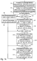
- Figure 1A shows a flowchart for illustrating a part of the operating method according to the invention, this part being run only once during a driving cycle, ie between switching on the ignition and engine start on the one hand and switching off the ignition and engine stop on the other.
- a first step S1 initially smaller limit values OSC1, OSC2,..., OSCn for the oxygen storage capacity (OSC: O xygen S torage C apacity) of the exhaust gas catalytic converter are set. It is OSC1>OSC2>...> OSCn.
- step S2 increasingly larger subareas A1, A2,... An are determined within the engine map, the engine map in FIG. 2 is shown schematically.
- A1 ⁇ A2 ⁇ ... ⁇ An applies.
- a step S3 the current value OSC of the oxygen storage capacity of the catalytic converter is then determined. This can be done, for example, by simply reading from the corresponding measured value memory of the engine control unit, since the OSC value is determined in any case as part of the on-board diagnosis.
- step S4 it is then checked whether the current value OSC is smaller than the largest OSC value OSC1.
- step S5 it is determined in steps S5 and S6 that no engine measures for improving the cleaning effect of the catalytic converter are initiated, i. neither ignition timing (step S5) nor lambda calibration (step S6). This then applies independently of the current operating point P of the internal combustion engine.
- a lambda adjustment for the partial regions A1, A2, A3 is then also set in a step S8, the lambda adjustment also being restricted to the partial region A1.
- a step S9 it is then checked whether the current OSC value falls below the next lower limit value OSC2, which indicates a further deterioration of the oxygen storage capacity of the catalytic converter.
- steps S10 and S11 another determination of the ignition retard adjustments and the lambda adjustments for the individual parts areas takes place A1, A2, A3 of the engine map.
- motor measures for improving the cleaning effect of the exhaust gas catalytic converter are then also provided for the partial area A2.
- the ignition angle adjustment and the lambda adjustment for the individual subareas A1, A2, A3 of the engine map are determined in steps S13 and S14. This means that motor measures for improving the cleaning effect of the catalytic converter can then be carried out in all sections A1, A2, A3.
- the flowchart according to FIG. 1 This clarifies the determination of the intensity of the engine measures as a function of the OSC value, which is measured only once within a driving cycle.
- the flowchart defined in accordance with Figure 1A the subregions of the engine map in which any engine measures to improve the cleaning effect of the catalytic converter are performed.
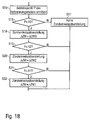
- the flowchart according to FIG. 1B shows the current operation of the internal combustion engine, wherein the steps S15-S22 are continuously repeated during operation of the motor vehicle.
- the flowchart will be according to Figure 1 B so go through during operation of the motor vehicle again at short intervals.
- a first step S15 the current operating point P of the internal combustion engine within the engine map is first determined according to FIG FIG. 2 determined, the operating point P in this embodiment, load torque M and speed n represents.
- a step S16 it is then checked whether the current operating point P lies within the comprehensive subarea A3 of the engine map. If this is not the case, the operating point P does not lie in any of the subareas A1, A2, A3, so that it is then determined in a step S17 that no retardation of the ignition angle takes place.
- an ignition retard ⁇ ZW is set to the value ⁇ ZW3 previously described in the flowchart of FIG Figure 1A was determined.
- step S19 it is then checked whether the operating point P is also within the narrower subarea A2.
- the ignition retard ⁇ ZW is set to the value ⁇ ZW2 in the flowchart shown in FIG Figure 1A for sub-area A2.
- step S22 the ignition retard ⁇ ZW is set to the value ⁇ ZW1 previously described in the flowchart of FIG Figure 1A was intended for the subarea A1.
- the flowchart according to Figure 1C shows the lambda adjustment, which is repeated during ongoing operation of the internal combustion engine also at small intervals.
- the current operating point of the internal combustion engine is first determined in a step S23.
- step S25 it is determined in step S25 that no lambda adjustment takes place.
- the lambda adjustment ⁇ is set to the value ⁇ 3 previously described in the flowchart of FIG Figure 1A for the sub-area A3.
- the lambda adjustment ⁇ is set to the value ⁇ 2 in the step S28, which in the flowchart according to FIG Figure 1A for sub-area A2.
- step S29 it is then checked in a step S29 whether the current operating point P of the internal combustion engine is even in the narrowest subarea A1.
- the lambda adjustment ⁇ is set to the value ⁇ in the step S30, which in the flowchart according to FIG Figure 1A was intended for the subarea A1.
- FIG. 3 shows a simplified schematic representation of a drive system according to the invention with an internal combustion engine 1 with an injection system 2, an ignition system 3 and an exhaust gas catalyst 4, which is arranged in the exhaust line 5 of the internal combustion engine 1.
- the drive system also has a control unit 6, which is controlled by numerous sensor variables and controls the injection system 2 with a lambda value, the control unit 6 allowing a corresponding lambda adjustment in order to improve the cleaning effect of the exhaust gas catalytic converter 4.
- control unit 6 also controls the ignition system 3 and allows a corresponding Zündwinkels Georgtvergna, as has already been described in detail above.
Landscapes
- Engineering & Computer Science (AREA)
- Chemical & Material Sciences (AREA)
- Combustion & Propulsion (AREA)
- Mechanical Engineering (AREA)
- General Engineering & Computer Science (AREA)
- Chemical Kinetics & Catalysis (AREA)
- Health & Medical Sciences (AREA)
- Toxicology (AREA)
- Materials Engineering (AREA)
- Exhaust Gas After Treatment (AREA)
Abstract
Description
- Die Erfindung betrifft ein Betriebsverfahren für eine Abgasreinigungsanlage mit einem Abgaskatalysator (z. B. Dreiwegekatalysator) zur Abgasreinigung an einem Verbrennungsmotor, insbesondere in einem Kraftfahrzeug. Weiterhin betrifft die Erfindung ein Antriebssystem, insbesondere für ein Kraftfahrzeug mit einem Verbrennungsmotor und einem Abgaskatalysator.
- Aus dem Stand der Technik sind zur Abgasreinigung an einem Verbrennungsmotor Abgasreinigungsanlagen bekannt, die Dreiwegekatalysatoren einsetzen. Derartige Dreiwegekatalysatoren unterliegen jedoch einer natürlichen und durch Umwelteinflüsse beeinflussten Alterung, wodurch die sogenannte "Light-off-Temperatur" zunimmt, ab welcher der Abgaskatalysator wirksam ist und eine ausreichende Reinigungswirkung bietet. Bei Verbrennungsmotoren mit relativ geringer Abgastemperatur besteht daher die Gefahr, dass in Teilen des Motorenkennfelds keine ausreichende Schadstoffkonvertierung in dem Dreiwegekatalysator stattfindet, da die "Light-off-Temperatur" des Abgaskatalysators im Betrieb nicht erreicht wird. Um dem entgegenzuwirken, wird in Abhängigkeit von dem Katalysatorzustand die Abgastemperatur erhöht, was beispielsweise durch eine Zündwinkelverstellung erfolgen kann. Als Maß für den Katalysatorzustand wird üblicherweise die Sauerstoffspeicherfähigkeit (OSC: Oxygen Storage Capacity) des Abgaskatalysators verwendet. Dieser OSC-Wert wird im Rahmen der On-Board-Diagnose ohnehin regelmäßig gemessen und steht daher als Messgröße im Motorsteuergerät zur Verfügung. Es ist also aus dem Stand der Technik bekannt, eine Katalysator-Kenngröße (OSC-Wert) des Abgaskatalysators zu ermitteln, welche die Reinigungswirkung des Abgaskatalysators wiedergibt. Weiterhin ist es aus dem Stand der Technik bekannt, in Abhängigkeit von der ermittelten Katalysator-Kenngröße des Abgaskatalysators motorische Maßnahmen durchzuführen (z. B. Zündwinkelverstellung), um die Reinigungswirkung des Abgaskatalysators zu verbessern, wenn die ermittelte Katalysator-Kenngröße (OSC-Wert) eine unzureichende Reinigungswirkung des Abgaskatalysators anzeigt.
- Nachteilig an diesem bekannten Verfahren ist die Tatsache, dass die motorischen Maßnahmen (z. B. Zündwinkelspätverstellung) zur Verbesserung der Reinigungswirkung des Abgaskatalysators einen Kraftstoffmehrverbrauch und entsprechend erhöhte CO2-Emissionen zur Folge haben. Es besteht also bei diesem bekannten Verfahren ein Zielkonflikt zwischen der
- Optimierung der Reinigungswirkung des Abgaskatalysators einerseits und der Minimierung des Kraftstoffverbrauchs und der CO2-Emission andererseits.
- Der Erfindung liegt deshalb die Aufgabe zugrunde, dieses Problem zu lösen.
- Diese Aufgabe wird durch ein erfindungsgemäßes Betriebsverfahren für eine Abgasreinigungsanlage bzw. durch ein entsprechendes Antriebssystem gemäß den unabhängigen Ansprüchen gelöst.
- Die Erfindung beruht auf der technisch-physikalischen Erkenntnis, dass der mit der Alterung des Abgaskatalysators verbundene Anstieg der "Light-off-Temperatur" nur in Teilen des Motorenkennfeldes problematisch ist, wenn die tatsächliche Abgastemperatur die alterungsbedingt angestiegene "Light-off-Temperatur" nicht übersteigt.
- Beispielsweise ist die Abgastemperatur im Volllastbetrieb (z. B. bei einer schnellen Autobahnfahrt) in der Regel hinreichend groß, um auch eine altersbedingt angestiegene "Light-off-Temperatur" zu übersteigen, so dass in diesem Betriebspunkt auch keine motorischen Maßnahmen erforderlich sind, um die Reinigungswirkung des Abgaskatalysators zu verbessern. Vielmehr sollten solche verbrauchssteigernden motorischen Maßnahmen in einem solchen Betriebspunkt unterbleiben, da sie zur Verbesserung der Reinigungswirkung nicht erforderlich sind, aber den Kraftstoffverbrauch und damit die CO2-Emissionen erhöhen würden.
- In einem anderen Betriebspunkt (z. B. im Teillastbetrieb im Stadtverkehr) sind die Abgastemperaturen dagegen relativ niedrig und unterschreiten deshalb möglicherweise die altersbedingt angestiegene "Light-off-Temperatur" des Abgaskatalysators. In einem solchen Betriebspunkt ist es dann erforderlich, motorische Maßnahmen (z. B. Zündwinkelverstellung) zu ergreifen, um die Reinigungswirkung des Abgaskatalysators zu verbessern, wobei dann auch ein Kraftstoffmehrverbrauch und entsprechend erhöhte CO2-Emissionen in Kauf genommen werden.
- Die Erfindung sieht deshalb vor, dass die motorischen Maßnahmen (z. B. Zündwinkelverstellung) zur Verbesserung der Reinigungswirkung des Abgaskatalysators nicht nur - wie beim Stand der Technik - in Abhängigkeit von der ermittelten Katalysator-Kenngröße (z. B. OSC-Wert) durchgeführt werden, sondern auch in Abhängigkeit von dem Betriebspunkt des Verbrennungsmotors. Vorzugsweise werden die motorischen Maßnahmen zur Verbesserung der Reinigungswirkung des Abgaskatalysators im Rahmen der Erfindung nur dann durchgeführt, wenn zwei Bedingungen erfüllt sind. Zum einen muss die ermittelte Katalysator-Kenngröße (z. B. OSC-Wert) anzeigen, dass die Reinigungswirkung des Abgaskatalysators abgesunken ist. Zum anderen muss der Betriebspunkt des Verbrennungsmotors innerhalb des Motorkennfeldes in einem Bereich liegen, in dem aktuell eine Verbesserung der Reinigungswirkung erforderlich ist, so dass dann entsprechend motorische Maßnahmen zur Verbesserung der Reinigungswirkung des Abgaskatalysators eingeleitet werden müssen. Beispielsweise sind im Volllastbetrieb bei hohen Abgastemperaturen in der Regel keine motorischen Maßnahmen erforderlich, um die Reinigungswirkung des Abgaskatalysators zu verbessern, wohingegen ein Teillastbetrieb (z. B. im Stadtverkehr) mit entsprechend niedrigen Abgastemperaturen die Verbesserung der Reinigungswirkung erforderlich machen kann.
- In einem bevorzugten Ausführungsbeispiel der Erfindung hängt die Durchführung der motorischen Maßnahmen (z. B. Zündwinkelverstellung) zur Verbesserung der Reinigungswirkung des Abgaskatalysators nicht nur qualitativ von dem aktuellen Betriebspunkt des Verbrennungsmotors ab, in dem Sinne, dass entweder motorische Maßnahmen eingeleitet werden oder nicht. Vielmehr ist in dem bevorzugten Ausführungsbeispiel der Erfindung auch vorgesehen, dass die Intensität der motorischen Maßnahme zur Verbesserung der Reinigungswirkung in Abhängigkeit von dem Betriebspunkt des Verbrennungsmotors und in Abhängigkeit der ermittelten Katalysator-Kenngröße quantitativ flexibel festgelegt wird.
- Bei einer Zündwinkelverstellung kann beispielsweise der Verstellwinkel als Funktion der ermittelten Katalysator-Kenngröße und/oder als Funktion des aktuellen Betriebspunktes des Verbrennungsmotors flexibel festgelegt werden, d.h. mit betriebspunktabhängig unterschiedlichen Verstellwinkeln.
- Weiterhin besteht die Möglichkeit, dass die motorischen Maßnahmen zur Verbesserung der Reinigungswirkung des Abgaskatalysators nur in einem bestimmten Teilbereich des Motorkennfeldes eingeleitet werden, wobei dieser Teilbereich in Abhängigkeit von der ermittelten Katalysator-Kenngröße flexibel festgelegt werden kann. Bei einem Abgaskatalysator mit einer großen Sauerstoffspeicherfähigkeit werden die motorischen Maßnahmen zur Verbesserung der Reinigungswirkung des Abgaskatalysators dann nur in einem kleinen Teilbereich des Motorkennfeldes freigegeben, wohingegen die motorischen Maßnahmen zur Verbesserung der Reinigungswirkung des Abgaskatalysators bei einem Abgaskatalysator mit einer alterungsbedingt geringen Sauerstoffspeicherfähigkeit in einem entsprechend größeren Teilbereich des Motorkennfeldes freigegeben werden.
- Es wurde bereits vorstehend darauf hingewiesen, dass die motorischen Maßnahmen (z. B. Zündwinkelverstellung) zur Verbesserung der Reinigungswirkung des Abgaskatalysators in der Regel zu einem Kraftstoffmehrverbrauch und zu entsprechend erhöhten CO2-Emissionen führen. Die Erhöhung des Kraftstoffverbrauchs durch die motorischen Maßnahmen (z. B. Zündwinkelverstellung) hängt auch von dem aktuellen Betriebspunkt des Verbrennungsmotors innerhalb des Motorkennfeldes ab. So führen die motorischen Maßnahmen (z. B. Zündwinkelverstellung) zur Verbesserung der Reinigungswirkung des Abgaskatalysators in einigen Betriebspunkten nur zu einem relativ geringen Kraftstoffmehrverbrauch und in anderen Betriebspunkten zu einem relativ hohen Kraftstoffmehrverbrauch. Die Erfindung sieht deshalb vorzugsweise vor, dass der Teilbereich des Motorenkennfeldes für die Durchführung der motorischen Maßnahmen zur Verbesserung der Reinigungswirkung des Abgaskatalysators mit zunehmender Verschlechterung der ermittelten Katalysator-Kenngröße (z. B. OSC-Wert) zunehmend ausgedehnt wird und zwar ausgehend von einem Bereich mit einer relativ geringen Erhöhung des Kraftstoffverbrauchs hin zu einem Bereich mit einer relativ großen Erhöhung des Kraftstoffverbrauchs. Bei einer geringfügigen Verschlechterung der Reinigungswirkung des Abgaskatalysators werden die motorischen Maßnahmen zur Verbesserung der Reinigungswirkung des Abgaskatalysators dann auch nur in einem Teilbereich des Motorkennfeldes durchgeführt, in dem die motorischen Maßnahmen nur einen geringen Kraftstoffmehrverbrauch verursachen. Bei einer größeren Verschlechterung der Reinigungswirkung des Abgaskatalysators werden die motorischen Maßnahmen (z. B. Zündwinkelverstellung) zur Verbesserung der Reinigungswirkung des Abgaskatalysators dagegen auch in Teilbereichen des Motorkennfeldes freigegeben, indem die motorischen Maßnahmen zu einem größeren Kraftstoffmehrverbrauch führen.
- Es wurde bereits vorstehend erwähnt, dass es sich bei der ermittelten Katalysator-Kenngröße um die Sauerstoffspeicherfähigkeit des Abgaskatalysators handeln kann. Dies ist vorteilhaft, weil der sogenannte OSC-Wert im Rahmen der On-Board-Diagnose ohnehin regelmäßig gemessen wird und deshalb im Motorsteuergerät als Messgröße zur Verfügung steht. Die Erfindung ist jedoch hinsichtlich der Katalysator-Kenngröße nicht auf die Ermittlung des OSC-Werts des Abgaskatalysators beschränkt. Vielmehr kann die Erfindung grundsätzlich auch realisiert werden, indem eine andere Katalysator-Kenngröße ermittelt wird, welche die Reinigungswirkung des Abgaskatalysators wiedergibt.
- Weiterhin ist zu der Katalysator-Kenngröße zu erwähnen, dass diese vorzugsweise nur einmal während eines Fahrzyklus ermittelt wird, wobei sich ein Fahrzyklus vom Einschalten der Zündung und dem anschließenden Motorstart bis zum anschließenden Motorstopp und dem Ausschalten der Zündung erstreckt. Die Messung des aktuellen Betriebspunktes des Verbrennungsmotors erfolgt dagegen vorzugsweise laufend während des Betriebs, d.h. in kurzen Zeitabständen vielfach während eines Fahrzyklus.
- Der vorstehend erwähnte Betriebspunkt des Verbrennungsmotors gibt vorzugsweise mindestens zwei der folgenden Größen wieder:
- Drehzahl der Kurbelwelle,
- Drehzahl der Nockenwelle,
- Lastmoment,
- Luftmassenstrom,
- Druck im Saugrohr.
- In dem bevorzugten Ausführungsbeispiel der Erfindung ist das Motorkennfeld jedoch zweidimensional, wobei der Betriebspunkt die Drehzahl von Kurbelwelle bzw. Nockenwelle und das Lastmoment wiedergibt.
- Weiterhin wurde vorstehend bereits erwähnt, dass es sich bei der motorischen Maßnahme zur Verbesserung der Reinigungswirkung des Abgaskatalysators um eine Zündwinkelverstellung handeln kann, wobei der Zündwinkel vorzugsweise in Richtung eines späteren Zündzeitpunkts verstellt wird. Eine derartige Zündwinkelverstellung zur Verbesserung der Reinigungswirkung des Abgaskatalysators ist an sich aus dem Stand der Technik bekannt und muss deshalb nicht weiter beschrieben werden. Zur Vermeidung von Missverständnissen ist jedoch darauf hinzuweisen, dass die Zündwinkelverstellung im Stand der Technik nur in Abhängigkeit von dem OSC-Wert durchgeführt wird, nicht dagegen in Abhängigkeit von dem aktuellen Betriebspunkt des Verbrennungsmotors.
- Darüber hinaus besteht im Rahmen der Erfindung die Möglichkeit, dass es sich bei der motorischen Maßnahme zur Verbesserung der Reinigungswirkung des Abgaskatalysators um eine Veränderung des Lambda-Wertes handelt, d.h. des Verhältnisses von Luft und Kraftstoff im Vergleich zu einem stöchiometrischen Gemisch mit λ=1. Zur Verbesserung der Reinigungswirkung des Abgaskatalysators wird der Lambda-Wert dann vorzugsweise hin zu einem fetteren Kraftstoff-Luft-Gemisch verstellt.
- Die beiden vorstehend genannten motorischen Maßnahmen (Zündwinkelverstellung, Lambda-Verstellung) können im Rahmen der Erfindung allein oder in Kombination miteinander eingesetzt werden. Darüber hinaus können im Rahmen der Erfindung auch andere motorische Maßnahmen eingesetzt werden, um die Reinigungswirkung des Abgaskatalysators zu verbessern.
- Neben dem vorstehend beschriebenen Betriebsverfahren beansprucht die Erfindung auch Schutz für ein entsprechendes Antriebssystem, das beispielsweise in einem Kraftfahrzeug (z. B. Lastkraftwagen, Omnibus) eingesetzt werden kann, um das Kraftfahrzeug anzutreiben.
- Das erfindungsgemäße Antriebssystem weist zunächst einen Verbrennungsmotor auf, wobei es sich beispielsweise um einen Otto-Motor handeln kann, insbesondere um einen Ottomotorisch betriebenen Gasmotor. Es besteht jedoch im Rahmen der Erfindung auch die Möglichkeit, dass der Verbrennungsmotor ein Dieselmotor ist.
- Weiterhin umfasst das erfindungsgemäße Antriebssystem einen Abgaskatalysator (z. B. Dreiwegekatalysator), der im Abgasstrang des Verbrennungsmotors angeordnet ist.
- Darüber hinaus umfasst das erfindungsgemäße Antriebssystem eine Steuereinheit, die eine Katalysator-Kenngröße (z. B. OSC-Wert) des Abgaskatalysators ermittelt, welche die Reinigungswirkung des Abgaskatalysators wiedergibt. Vorzugsweise wird diese Katalysator-Kenngröße (z. B. OSC-Wert) nur einmal während eines Fahrzyklus zwischen Motorstart und Motorstopp ermittelt.
- Ferner ermittelt die Steuereinheit einen Betriebspunkt des Verbrennungsmotors innerhalb eines Motorkennfeldes, wobei der Betriebspunkt beispielsweise Drehzahl und Lastmoment wiedergegeben kann.
- Darüber hinaus führt die Steuereinheit dann motorische Maßnahmen zur Verbesserung der Reinigungswirkung des Abgaskatalysators durch, wenn die ermittelte Katalysator-Kenngröße (z. B. OSC-Wert) anzeigt, dass die Reinigungswirkung des Abgaskatalysators unzureichend ist.
- Das erfindungsgemäße Antriebssystem zeichnet sich nun gegenüber dem Stand der Technik dadurch aus, dass die Steuereinheit die motorische Maßnahme zur Verbesserung der Reinigungswirkung des Abgaskatalysators auch in Abhängigkeit von dem Betriebspunkt des Verbrennungsmotors durchführt, wie es bereits vorstehend in Bezug auf das erfindungsgemäße Verfahren ausführlich beschrieben worden ist.
- Schließlich ist noch zu erwähnen, dass die Erfindung auch Schutz beansprucht für ein Kraftfahrzeug (z. B. Nutzfahrzeug, wie beispielsweise Lastkraftwagen oder Omnibus), das mit einem solchen erfindungsgemäßen Antriebssystem ausgestattet ist.
- Andere vorteilhafte Weiterbildungen der Erfindung sind in den Unteransprüchen gekennzeichnet oder werden nachstehend zusammen mit der Beschreibung des bevorzugten Ausführungsbeispiels der Erfindung anhand der Figuren näher erläutert. Es zeigen:
- Figur 1A
- ein Flussdiagramm zur Ermittlung des OSC-Werts und der Intensität der motorischen Maßnahmen zur Verbesserung der Reinigungswirkung des Abgaskatalysators,
- Figur 1B
- ein Flussdiagramm zur Verdeutlichung der Zündwinkelverstellung in Abhängigkeit von dem aktuellen Betriebspunkt des Verbrennungsmotors,
- Figur 1C
- ein Flussdiagramm zur Verdeutlichung der Lambdaverstellung in Abhängigkeit von dem aktuellen Betriebspunkt des Verbrennungsmotors,
- Figur 2
- ein exemplarisches Motorkennfeld mit verschiedenen Teilbereichen zur Betriebspunktabhängigen Festlegung der motorischen Maßnahmen (z. B. Zündwinkelverstellung, Lambdaverstellung) zur Verbesserung der Reinigungswirkung des Abgaskatalysators sowie
- Figur 3
- ein erfindungsgemäßes Antriebssystem für ein Kraftfahrzeug.
-
Figur 1A zeigt ein Flussdiagramm zur Verdeutlichung eines Teils des erfindungsgemäßen Betriebsverfahrens, wobei dieser Teil nur einmal während eines Fahrzyklus durchlaufen wird, d.h. zwischen Einschalten der Zündung und Motorstart einerseits und Ausschalten der Zündung und Motorstopp andererseits. - In einem ersten Schritt S1 werden zunächst zunehmend kleinere Grenzwerte OSC1, OSC2, ... , OSCn für die Sauerstoffspeicherfähigkeit (OSC: Oxygen Storage Capacity) des Abgaskatalysators festgelegt. Es gilt OSC1>OSC2>...>OSCn.
- In einem weiteren Schritt S2 werden dann zunehmend größere Teilbereiche A1, A2, ... An innerhalb des Motorkennfeldes festgelegt, wobei das Motorkennfeld in
Figur 2 schematisch dargestellt ist. Für die Teilbereiche A1, A2, ...An gilt also A1 <A2<... <An. - Die folgende Beschreibung und die Figuren zeigt Beispielhaft ein System mit drei Teilbereichen und drei OSC-Grenzwerten.
- In einem Schritt S3 wird dann der aktuelle Wert OSC der Sauerstoffspeicherfähigkeit des Abgaskatalysators ermittelt. Dies kann beispielsweise durch einfaches Auslesen aus dem entsprechenden Messwertspeicher des Motorsteuergeräts geschehen, da der OSC-Wert ohnehin im Rahmen der On-Board-Diagnose ermittelt wird.
- In einem weiteren Schritt S4 wird dann geprüft, ob der aktuelle Wert OSC kleiner ist als der größte OSC-Wert OSC1.
- Falls dies nicht der Fall ist, so wird in den Schritten S5 und S6 festgelegt, dass keine motorischen Maßnahmen zur Verbesserung der Reinigungswirkung des Abgaskatalysators eingeleitet werden, d.h. weder eine Zündwinkelverstellung (Schritt S5) noch eine LambdaVerstellung (Schritt S6). Dies gilt dann unabhängig von dem aktuellen Betriebspunkt P des Verbrennungsmotors.
- Falls der aktuelle OSC-Wert jedoch den größten Grenzwert OSC1 unterschreitet, so wird in einem Schritt S7 eine Zündwinkelverstellung ΔZWi für die verschiedenen Teilbereiche A1, A2, A3 eingestellt. Hierbei beschränkt sich die Zündwinkelverstellung zunächst auf den kleinsten Teilbereich A1 des Motorkennfeldes, wohingegen für die anderen Teilbereiche A2, A3 noch keine Zündwinkelverstellung eingestellt wird. Dies ist zunächst sinnvoll, da bei einem OSC-Wert OSC2<OSC<OSC1 nur relativ geringfügige motorische Maßnahmen erforderlich sind, um die Reinigungswirkung zu verbessern. Es wäre deshalb nicht sinnvoll, die Zündwinkelverstellung auch in den Teilbereichen A2 und A3 durchzuführen, da dies dort nur zu einem unerwünschten Kraftstoffmehrverbrauch führen würde.
- Darüber hinaus wird dann auch in einem Schritt S8 eine Lambdaverstellung für die Teilbereiche A1, A2, A3 eingestellt, wobei auch die Lambdaverstellung auf den Teilbereich A1 beschränkt ist.
- In einem Schritt S9 wird dann geprüft, ob der aktuelle OSC-Wert den nächstkleineren Grenzwert OSC2 unterschreitet, was auf eine weitergehende Verschlechterung der Sauerstoffspeicherfähigkeit des Abgaskatalysators hindeutet.
- Falls dies der Fall ist, so erfolgt in den Schritten S10 und S11 eine andere Festlegung der Zündwinkelspätverstellungen und der Lambdaverstellungen für die einzelnen Teilebereiche A1, A2, A3 des Motorkennfeldes. Bei dieser weitergehenden Verschlechterung der Sauerstoffspeicherfähigkeit werden dann auch für den Teilbereich A2 motorische Maßnahmen zur Verbesserung der Reinigungswirkung des Abgaskatalysators vorgesehen.
- Schließlich wird dann in einem Schritt S12 geprüft, ob der aktuelle OSC-Wert OSC auch den kleinsten Grenzwert OSC3 unterschreitet.
- Falls dies der Fall ist, so wird in den Schritten S13 und S14 die Zündwinkelverstellung und die Lambdaverstellung für die einzelnen Teilbereiche A1, A2, A3 des Motorkennfeldes festgelegt. Dies bedeutet, dass dann in allen Teilbereichen A1, A2, A3 motorische Maßnahmen zur Verbesserung der Reinigungswirkung des Abgaskatalysators durchgeführt werden können.
- Das Flussdiagramm gemäß
Figur 1 verdeutlicht also die Festlegung der Intensität der motorischen Maßnahmen in Abhängigkeit von dem OSC-Wert, der innerhalb eines Fahrzyklus nur einmal gemessen wird. Darüber hinaus definiert das Flussdiagramm gemäßFigur 1A die Teilbereiche des Motorkennfeldes, in denen überhaupt motorische Maßnahmen zur Verbesserung der Reinigungswirkung des Abgaskatalysators durchgeführt werden. - Das Flussdiagramm gemäß
Figur 1B zeigt den laufenden Betrieb des Verbrennungsmotors, wobei die Schritte S15-S22 während des Betriebs des Kraftfahrzeugs laufend wiederholt werden. Im Gegensatz zu dem Flussdiagramm gemäßFigur 1B wird das Flussdiagramm gemäßFigur 1 B also während des Betriebs des Kraftfahrzeugs immer wieder in kurzen Zeitabständen durchlaufen. - In einem ersten Schritt S15 wird zunächst der aktuelle Betriebspunkt P des Verbrennungsmotors innerhalb des Motorkennfeldes gemäß
Figur 2 ermittelt, wobei der Betriebspunkt P in diesem Ausführungsbeispiel Lastmoment M und Drehzahl n wiedergibt. - In einem Schritt S16 wird dann geprüft, ob der aktuelle Betriebspunkt P innerhalb des umfassenden Teilbereichs A3 des Motorkennfeldes liegt. Falls dies nicht der Fall ist, so liegt der Betriebspunkt P in keinem der Teilbereiche A1, A2, A3, so dass dann in einem Schritt S17 festgelegt wird, dass keine Zündwinkelspätverstellung erfolgt.
- Andernfalls wird dagegen in einem Schritt S18 eine Zündwinkelspätverstellung ΔZW auf den Wert ΔZW3 festgelegt, der zuvor in dem Flussdiagramm gemäß
Figur 1A festgelegt wurde. - In einem weiteren Schritt S19 wird dann geprüft, ob der Betriebspunkt P auch innerhalb des engeren Teilbereichs A2 liegt.
- Falls dies der Fall ist, so wird in einem Schritt S20 die Zündwinkelspätverstellung ΔZW auf den Wert ΔZW2 festgesetzt, der in dem Flussdiagramm gemäß
Figur 1A für den Teilbereich A2 vorgesehen wurde. - Anschließend wird dann in einem Schritt S21 geprüft, ob der aktuelle Betriebspunkt P innerhalb des engeren Teilbereichs A1 liegt.
- Falls dies der Fall ist, so wird in dem Schritt S22 die Zündwinkelspätverstellung ΔZW auf den Wert ΔZW1 festgesetzt, der zuvor in dem Flussdiagramm gemäß
Figur 1A für den Teilbereich A1 vorgesehen wurde. - Das Flussdiagramm gemäß
Figur 1C zeigt die Lambdaverstellung, die während des laufenden Betriebs des Verbrennungsmotors ebenfalls in geringen Zeitabständen wiederholt wird. - Auch hierbei wird in einem Schritt S23 zunächst der aktuelle Betriebspunkt des Verbrennungsmotors ermittelt.
- Anschließend wird dann in einem Schritt S24 geprüft, ob der aktuelle Betriebspunkt P innerhalb des umfassenden Teilbereichs A3 liegt.
- Falls dies nicht der Fall ist, so wird in dem Schritt S25 festgelegt, dass keine Lambdaverstellung erfolgt.
- Andernfalls wird in einem Schritt S26 die Lambdaverstellung Δλ auf den Wert Δλ3 festgesetzt, der zuvor in dem Flussdiagramm gemäß
Figur 1A für den Teilbereich A3 festgelegt wurde. - Anschließend wird in einem Schritt S27 geprüft, ob sich der aktuelle Betriebspunkt P des Verbrennungsmotors in dem kleineren Teilbereich A2 befindet.
- Falls dies der Fall ist, so wird die Lambdaverstellung Δλ in dem Schritt S28 auf den Wert Δλ2 festgesetzt, der in dem Flussdiagramm gemäß
Figur 1A für den Teilbereich A2 vorgesehen wurde. - Anschließend wird dann in einem Schritt S29 geprüft, ob der aktuelle Betriebspunkt P des Verbrennungsmotors sogar in dem engsten Teilbereich A1 liegt.
- Falls dies der Fall ist, so wird die Lambdaverstellung Δλ in dem Schritt S30 auf den Wert Δλ festgesetzt, der in dem Flussdiagramm gemäß
Figur 1A für den Teilbereich A1 vorgesehen wurde. -
Figur 3 zeigt eine vereinfachte schematische Darstellung eines erfindungsgemäßen Antriebssystems mit einem Verbrennungsmotor 1 mit einer Einspritzanlage 2, einer Zündanlage 3 und einem Abgaskatalysator 4, der im Abgasstrang 5 des Verbrennungsmotors 1 angeordnet ist. - Darüber hinaus weist das Antriebssystem noch ein Steuergerät 6 auf, das von zahlreichen Sensorgrößen angesteuert wird und die Einspritzanlage 2 mit einem Lambda-Wert ansteuert, wobei das Steuergerät 6 eine entsprechende Lambdaverstellung ermöglicht, um die Reinigungswirkung des Abgaskatalysators 4 zu verbessern.
- Darüber hinaus steuert das Steuergerät 6 auch die Zündanlage 3 an und ermöglicht eine entsprechende Zündwinkelspätverstellung, wie bereits vorstehend ausführlich beschrieben worden ist.
- Die Erfindung ist nicht auf das vorstehend beschriebene bevorzugte Ausführungsbeispiel beschränkt. Vielmehr ist eine Vielzahl von Varianten und Abwandlungen möglich, die ebenfalls von dem Erfindungsgedanken Gebrauch machen und deshalb in den Schutzbereich fallen. Insbesondere beansprucht die Erfindung auch Schutz für den Gegenstand der Unteransprüche unabhängig von den jeweils in Bezug genommenen Ansprüchen und insbesondere ohne die Merkmale des Hauptanspruchs.
-
- 1
- Verbrennungsmotor
- 2
- Einspritzanlage
- 3
- Zündanlage
- 4
- Abgaskatalysator
- 5
- Abgasstrang
- ZWSOLL
- Sollwert des Zündwinkels
- ΔZW
- Verstellwinkel des Zündwinkels zur Verbesserung der Reinigungswirkung des Abgaskatalysators
- ΔZW1
- Verstellwinkel des Zündwinkels im Teilbereich A1
- ΔZW2
- Verstellwinkel des Zündwinkels im Teilbereich A2
- ΔZW3
- Verstellwinkel des Zündwinkels im Teilbereich A3
- λSOLL
- Sollwert des Lambdawerts
- Δλ
- Verstellwert des Lambdawerts zur Verbesserung der Reinigungswirkung des Abgaskatalysators
- Δλ1
- Verstellwert des Lambdawerts im Teilbereich A1
- Δλ2
- Verstellwert des Lambdawerts im Teilbereich A2
- Δλ3
- Verstellwert des Lambdawerts im Teilbereich A3
- P
- Betriebspunkt des Verbrennungsmotors
- M
- Lastmoment des Verbrennungsmotors
- n
- Drehzahl des Verbrennungsmotors
- A1, A2, A3
- Teilbereiche des Motorkennfeldes
- OSC
- Sauerstoffspeicherfähigkeit des Abgaskatalysators
Claims (12)
- Betriebsverfahren für eine Abgasreinigungsanlage mit einem Abgaskatalysator (4), insbesondere mit einem Dreiwegekatalysator, zur Abgasreinigung an einem Verbrennungsmotor (1), insbesondere in einem Kraftfahrzeug, mit den folgenden Schritten:a) Ermitteln einer Katalysator-Kenngröße (OSC) des Abgaskatalysators (4), wobei die Katalysator-Kenngröße (OSC) die Reinigungswirkung des Abgaskatalysators (4) wiedergibt, undb) Durchführen einer motorischen Maßnahme zur Verbesserung der Reinigungswirkung des Abgaskatalysators (4), wenn die Katalysator-Kenngröße (OSC) eine unzureichende Reinigungswirkung des Abgaskatalysators (4) anzeigt, undc) Ermitteln eines Betriebspunkts (P) des Verbrennungsmotors (1) in einem Motorkennfeld, dadurch gekennzeichnet,d) dass die motorische Maßnahme zur Verbesserung der Reinigungswirkung des Abgaskatalysators (4) in Abhängigkeit von dem Betriebspunkt (P) des Verbrennungsmotors (1) eingeleitet wird.
- Betriebsverfahren nach Anspruch 1, dadurch gekennzeichnet, dass die Intensität der motorischen Maßnahme zur Verbesserung der Reinigungswirkung des Abgaskatalysators (4) in Abhängigkeit von dem Betriebspunkt (P) des Verbrennungsmotors (1) und in Abhängigkeit von der ermittelten Katalysator-Kenngröße (OSC) flexibel festgelegt wird.
- Betriebsverfahren nach einem der vorhergehenden Ansprüche, gekennzeichnet durch folgende Schritte:a) Festlegen eines Teilbereichs (A1, A2,..., An) des Motorkennfelds für die motorische Maßnahme zur Verbesserung der Reinigungswirkung des Abgaskatalysators (4),b) Prüfung, ob der Betriebspunkt (P) des Verbrennungsmotors (1) innerhalb des Teilbereichs (A1, A2, ..., An) liegt, undc) Durchführen der motorischen Maßnahme zur Verbesserung der Reinigungswirkung des Abgaskatalysators (4) nur dann, wenn der Betriebspunkt (P) des Verbrennungsmotors (1) innerhalb des festgelegten Teilbereichs (A1, A2,..., An) des Motorkennfeldes liegt.
- Betriebsverfahren nach Anspruch 3, dadurch gekennzeichnet, dass der Teilbereich (A1, A2,..., An) des Motorkennfeldes für die motorische Maßnahme zur Verbesserung der Reinigungswirkung des Abgaskatalysators (4) in Abhängigkeit von der ermittelten Katalysator-Kenngröße (OSC) festgelegt wird.
- Betriebsverfahren nach Anspruch 4, gekennzeichnet durch folgende Schritte:a) Ermitteln der Position des Betriebspunkts (P) des Verbrennungsmotors (1) innerhalb des Teilbereichs (A1, A2, ..., An) des Motorkennfelds, undb) Festlegen der Intensität der motorischen Maßnahme zur Verbesserung der Reinigungswirkung des Abgaskatalysators (4) in Abhängigkeit von der Position des Betriebspunktes innerhalb des Teilbereichs (A1, A2, ..., An) des Motorkennfelds.
- Betriebsverfahren nach einem der Ansprüche 3 bis 5, dadurch gekennzeichnet,a) dass die motorische Maßnahme zur Verbesserung der Reinigungswirkung des Abgaskatalysators (4) den Kraftstoffverbrauch des Verbrennungsmotors (1) erhöht, undb) dass die Erhöhung des Kraftstoffverbrauchs von dem Betriebspunkt (P) abhängt, in dem die motorische Maßnahme zur Verbesserung der Reinigungswirkung des Abgaskatalysators (4) durchgeführt wird, undc) dass der Teilbereich (A1, A2, ..., An) des Motorkennfeldes für die Durchführung der motorischen Maßnahme zur Verbesserung der Reinigungswirkung des Abgaskatalysators (4) mit zunehmender Verschlechterung der Katalysator-Kenngröße (OSC) zunehmend ausgedehnt wird, undd) dass die Ausdehnung des Teilbereichs (A1, A2, ..., An) des Motorkennfeldes für die Durchführung der motorischen Maßnahme zur Verbesserung der Reinigungswirkung des Abgaskatalysators (4) ausgeht von einem Bereich (A1) mit einer relativ geringen Erhöhung des Kraftstoffverbrauchs hin zu einem Bereich (An) mit einer relativ großen Erhöhung des Kraftstoffverbrauchs.
- Betriebsverfahren nach einem der vorhergehenden Ansprüche, dadurch gekennzeichnet, dass die ermittelte Katalysator-Kenngröße (OSC) die Sauerstoffspeicherfähigkeit des Abgaskatalysators (4) ist.
- Betriebsverfahren nach einem der vorhergehenden Ansprüche, dadurch gekennzeichnet, dass der Betriebspunkt (P) des Verbrennungsmotors (1) mindestens zwei der folgenden Größen wiedergibt:a) Drehzahl (n) der Kurbelwelle,b) Drehzahl der Nockenwelle,c) Lastmoment (M),d) Luftmassenstrom,e) Druck im Saugrohr.
- Betriebsverfahren nach einem der vorhergehenden Ansprüche,
dadurch gekennzeichnet,a) dass in dem Verbrennungsmotor (1) ein Kraftstoff-Luft-Gemisch jeweils an einem bestimmten Zündwinkel (ZW) gezündet wird, undb) dass die motorische Maßnahme zur Verbesserung der Reinigungswirkung des Abgaskatalysators (4) eine Verstellung des Zündwinkels (ZW) umfasst, insbesondere in Richtung eines späteren Zündzeitpunkts. - Betriebsverfahren nach einem der vorhergehenden Ansprüche,
dadurch gekennzeichnet,a) dass im Abgas ein bestimmter Lambdawert (λ) eingestellt wird, der das Verhältnis von Luft zu Brennstoff im Vergleich zu einem stöchiometrischen Gemisch wiedergibt, undb) dass die motorische Maßnahme zur Verbesserung der Reinigungswirkung des Abgaskatalysators (4) eine Veränderung des Lambdawerts (λ) umfasst, insbesondere hin zu einem fetteren Kraftstoff-Luft-Gemisch. - Antriebssystem, insbesondere für ein Kraftfahrzeug, mita) einem Verbrennungsmotor (1), insbesondere einem Ottomotor, insbesondere einem ottomotorisch betriebenen Gasmotor,b) einem Abgaskatalysator (4), insbesondere einem Dreiwegekatalysator, im Abgasstrang des Verbrennungsmotors (1), undc) einer Steuereinheit (6),dadurch gekennzeichnet,c1) die eine Katalysator-Kenngröße (OSC) des Abgaskatalysators (4) ermittelt, welche die Reinigungswirkung des Abgaskatalysators (4) wiedergibt,
wobei die Katalysator-Kenngröße (OSC) vorzugsweise nur einmal während eines Fahrzyklus zwischen Motorstart und Motorstopp ermittelt wird, undc2) die einen Betriebspunkt (P) des Verbrennungsmotors (1) innerhalb eines Motorkennfelds ermittelt, undc3) die motorische Maßnahmen zur Verbesserung der Reinigungswirkung des Abgaskatalysators (4) durchführt, wenn die Katalysator-Kenngröße (OSC) eine unzureichende Reinigungswirkung des Abgaskatalysators (4) anzeigt,d) dass die Steuereinheit (6) die motorische Maßnahme zur Verbesserung der Reinigungswirkung des Abgaskatalysators (4) in Abhängigkeit von dem Betriebspunkt (P) des Verbrennungsmotors (1) durchführt. - Kraftfahrzeug, insbesondere Nutzfahrzeug, insbesondere Lastkraftwagen oder Omnibus, mit einem Antriebssystem nach Anspruch 11.
Applications Claiming Priority (1)
| Application Number | Priority Date | Filing Date | Title |
|---|---|---|---|
| DE102015007163.7A DE102015007163A1 (de) | 2015-06-03 | 2015-06-03 | Betriebsverfahren für eine Abgasreinigungsanlage und entsprechendes Antriebssystem |
Publications (2)
| Publication Number | Publication Date |
|---|---|
| EP3101255A1 true EP3101255A1 (de) | 2016-12-07 |
| EP3101255B1 EP3101255B1 (de) | 2018-04-18 |
Family
ID=55966968
Family Applications (1)
| Application Number | Title | Priority Date | Filing Date |
|---|---|---|---|
| EP16001015.3A Active EP3101255B1 (de) | 2015-06-03 | 2016-05-04 | Betriebsverfahren für eine abgasreinigungsanlage und entsprechendes antriebssystem |
Country Status (5)
| Country | Link |
|---|---|
| EP (1) | EP3101255B1 (de) |
| CN (1) | CN106246305B (de) |
| BR (1) | BR102016012448B1 (de) |
| DE (1) | DE102015007163A1 (de) |
| RU (1) | RU2721071C2 (de) |
Citations (4)
| Publication number | Priority date | Publication date | Assignee | Title |
|---|---|---|---|---|
| DE19843859A1 (de) * | 1998-09-25 | 2000-03-30 | Bosch Gmbh Robert | Katalysatorregenerationsverfahren |
| DE10141842A1 (de) * | 2001-08-27 | 2003-04-03 | Bosch Gmbh Robert | Verfahren, Computerprogramm, Steuer- und/oder Regelgerät zum Betreiben einer Brennkraftmaschine, sowie Brennkraftmaschine |
| DE10162115A1 (de) * | 2001-11-16 | 2003-06-26 | Volkswagen Ag | Verfahren und Vorrichtung zur Katalysatoraufheizung |
| DE10338181A1 (de) * | 2003-06-30 | 2005-07-07 | Volkswagen Ag | Verfahren und Vorrichtung zur Temperaturbeeinflussung eines Katalysatorsystems |
Family Cites Families (4)
| Publication number | Priority date | Publication date | Assignee | Title |
|---|---|---|---|---|
| JP4253294B2 (ja) * | 2004-11-15 | 2009-04-08 | 株式会社日立製作所 | エンジンの自己診断装置 |
| JP5754512B2 (ja) * | 2011-10-24 | 2015-07-29 | 日産自動車株式会社 | 火花点火式内燃機関及び火花点火式内燃機関の制御方法 |
| EP2808508B1 (de) * | 2012-01-27 | 2017-05-31 | Toyota Jidosha Kabushiki Kaisha | Steuerungsvorrichtung für einen verbrennungsmotor |
| WO2013179373A1 (ja) * | 2012-05-28 | 2013-12-05 | トヨタ自動車株式会社 | 触媒劣化判定システム |
-
2015
- 2015-06-03 DE DE102015007163.7A patent/DE102015007163A1/de not_active Withdrawn
-
2016
- 2016-05-04 EP EP16001015.3A patent/EP3101255B1/de active Active
- 2016-05-31 BR BR102016012448-4A patent/BR102016012448B1/pt active IP Right Grant
- 2016-06-02 RU RU2016121866A patent/RU2721071C2/ru active
- 2016-06-02 CN CN201610384000.5A patent/CN106246305B/zh active Active
Patent Citations (4)
| Publication number | Priority date | Publication date | Assignee | Title |
|---|---|---|---|---|
| DE19843859A1 (de) * | 1998-09-25 | 2000-03-30 | Bosch Gmbh Robert | Katalysatorregenerationsverfahren |
| DE10141842A1 (de) * | 2001-08-27 | 2003-04-03 | Bosch Gmbh Robert | Verfahren, Computerprogramm, Steuer- und/oder Regelgerät zum Betreiben einer Brennkraftmaschine, sowie Brennkraftmaschine |
| DE10162115A1 (de) * | 2001-11-16 | 2003-06-26 | Volkswagen Ag | Verfahren und Vorrichtung zur Katalysatoraufheizung |
| DE10338181A1 (de) * | 2003-06-30 | 2005-07-07 | Volkswagen Ag | Verfahren und Vorrichtung zur Temperaturbeeinflussung eines Katalysatorsystems |
Also Published As
| Publication number | Publication date |
|---|---|
| RU2016121866A3 (de) | 2019-11-14 |
| BR102016012448A2 (pt) | 2016-12-06 |
| CN106246305B (zh) | 2020-03-03 |
| RU2016121866A (ru) | 2017-12-07 |
| EP3101255B1 (de) | 2018-04-18 |
| BR102016012448B1 (pt) | 2022-07-12 |
| CN106246305A (zh) | 2016-12-21 |
| RU2721071C2 (ru) | 2020-05-15 |
| DE102015007163A1 (de) | 2016-12-08 |
Similar Documents
| Publication | Publication Date | Title |
|---|---|---|
| DE3408215C2 (de) | ||
| DE19630053B4 (de) | Verfahren und Vorrichtung zur kontinuierlichen und variablen Regelung einer Ventileinstellung eines Verbrennungsmotors | |
| DE3408223C2 (de) | ||
| DE102008003581B4 (de) | Verfahren und Vorrichtung zur Verringerung der Abgastemperatur bei einem Kraftfahrzeug | |
| DE102011011371B4 (de) | Adaptive Dieselmotorsteuerung bei Cetanzahlschwankungen | |
| DE112016004369B4 (de) | Motorsteuervorrichtung | |
| DE102018251720A1 (de) | Verfahren zur Ermittlung einer maximalen Speicherfähigkeit eines Abgaskomponentenspeichers eines Katalysators | |
| DE102005009104B3 (de) | Verfahren und Vorrichtung zum Steuern einer Brennkraftmaschine | |
| DE102016110632A1 (de) | Verfahren zur Regeneration eines Partikelfilters | |
| DE10026359B4 (de) | Abgasreinigungsanlage für eine fremdgezündete, aufgeladene Verbrennungskraftmaschine und Verfahren zum Betrieb derselben | |
| EP1086741A2 (de) | Verfahren zur Steuerung einer Regeneration eines Partikelfilters und einer Entschwefelung eines NOx-Speicherkatalysators | |
| DE10142669B4 (de) | Motorsteuerung und Verfahren zum Reinigen eines Katalysators in einer Abgasanlage einer Mehrzylinderbrennkraftmaschine | |
| DE4325307C2 (de) | Verfahren zur Steuerung der Kraftstoffzufuhr bei einer gemischverdichtenden Brennkraftmaschine | |
| DE102005061876A1 (de) | Verfahren und Vorrichtung zur Steuerung eines Abgasnachbehandlungssystems | |
| DE10003903B4 (de) | Vorrichtung und Verfahren zur Steuerung eines Betriebes eines Mehrzylindermotors für Kraftfahrzeuge mit einer mehrflutigen Abgasreinigungsanlage | |
| EP3101255B1 (de) | Betriebsverfahren für eine abgasreinigungsanlage und entsprechendes antriebssystem | |
| DE10101593B4 (de) | Verfahren zum Betreiben eines mit direkter Kraftstoffeinspritzung in den Brennraum versehenen Verbrennungsmotors | |
| DE10029504A1 (de) | Mehrstufiges Brennverfahren für Dieselmotoren mit niedriger Luftzahl | |
| DE102006014249A1 (de) | Verfahren zur Vorsteuerung eines Lambda-Wertes | |
| DE10305878B4 (de) | Verfahren zum Betreiben einer Brennkraftmaschine, Steuer- und/oder Regelgerät für eine Brennkraftmaschine, Computerprogramm und elektrisches Speichermedium einer Brennkraftmaschine | |
| DE4326464C2 (de) | Luft-Kraftstoff-Verhältnis-Regeleinrichtung für eine Brennkraftmaschine | |
| DE102009021793B4 (de) | Verfahren zum Bestimmen der Stickoxidemission im Brennraum eines Dieselmotors | |
| AT520760B1 (de) | Verfahren zur begrenzung eines motormoments | |
| WO2011117123A1 (de) | Verfahren und vorrichtung zur regelung der abgasrückführungsrate für verbrennungsmotoren im magerbetrieb | |
| DE10053674A1 (de) | Verfahren zur Temperierung eines in einem Abgasstrang von einer Verbrennungskraftmaschine zu einem Katalysator geführten Abgasstroms und entsprechendes Abgastemperiersystem |
Legal Events
| Date | Code | Title | Description |
|---|---|---|---|
| PUAI | Public reference made under article 153(3) epc to a published international application that has entered the european phase |
Free format text: ORIGINAL CODE: 0009012 |
|
| STAA | Information on the status of an ep patent application or granted ep patent |
Free format text: STATUS: THE APPLICATION HAS BEEN PUBLISHED |
|
| AK | Designated contracting states |
Kind code of ref document: A1 Designated state(s): AL AT BE BG CH CY CZ DE DK EE ES FI FR GB GR HR HU IE IS IT LI LT LU LV MC MK MT NL NO PL PT RO RS SE SI SK SM TR |
|
| AX | Request for extension of the european patent |
Extension state: BA ME |
|
| STAA | Information on the status of an ep patent application or granted ep patent |
Free format text: STATUS: REQUEST FOR EXAMINATION WAS MADE |
|
| 17P | Request for examination filed |
Effective date: 20170224 |
|
| RBV | Designated contracting states (corrected) |
Designated state(s): AL AT BE BG CH CY CZ DE DK EE ES FI FR GB GR HR HU IE IS IT LI LT LU LV MC MK MT NL NO PL PT RO RS SE SI SK SM TR |
|
| STAA | Information on the status of an ep patent application or granted ep patent |
Free format text: STATUS: EXAMINATION IS IN PROGRESS |
|
| 17Q | First examination report despatched |
Effective date: 20170704 |
|
| GRAP | Despatch of communication of intention to grant a patent |
Free format text: ORIGINAL CODE: EPIDOSNIGR1 |
|
| STAA | Information on the status of an ep patent application or granted ep patent |
Free format text: STATUS: GRANT OF PATENT IS INTENDED |
|
| INTG | Intention to grant announced |
Effective date: 20180119 |
|
| GRAS | Grant fee paid |
Free format text: ORIGINAL CODE: EPIDOSNIGR3 |
|
| GRAA | (expected) grant |
Free format text: ORIGINAL CODE: 0009210 |
|
| STAA | Information on the status of an ep patent application or granted ep patent |
Free format text: STATUS: THE PATENT HAS BEEN GRANTED |
|
| AK | Designated contracting states |
Kind code of ref document: B1 Designated state(s): AL AT BE BG CH CY CZ DE DK EE ES FI FR GB GR HR HU IE IS IT LI LT LU LV MC MK MT NL NO PL PT RO RS SE SI SK SM TR |
|
| REG | Reference to a national code |
Ref country code: GB Ref legal event code: FG4D Free format text: NOT ENGLISH |
|
| REG | Reference to a national code |
Ref country code: CH Ref legal event code: EP |
|
| REG | Reference to a national code |
Ref country code: AT Ref legal event code: REF Ref document number: 990746 Country of ref document: AT Kind code of ref document: T Effective date: 20180515 |
|
| REG | Reference to a national code |
Ref country code: IE Ref legal event code: FG4D Free format text: LANGUAGE OF EP DOCUMENT: GERMAN |
|
| REG | Reference to a national code |
Ref country code: DE Ref legal event code: R096 Ref document number: 502016000846 Country of ref document: DE |
|
| REG | Reference to a national code |
Ref country code: FR Ref legal event code: PLFP Year of fee payment: 3 |
|
| REG | Reference to a national code |
Ref country code: NL Ref legal event code: FP |
|
| REG | Reference to a national code |
Ref country code: SE Ref legal event code: TRGR |
|
| REG | Reference to a national code |
Ref country code: LT Ref legal event code: MG4D |
|
| PG25 | Lapsed in a contracting state [announced via postgrant information from national office to epo] |
Ref country code: BG Free format text: LAPSE BECAUSE OF FAILURE TO SUBMIT A TRANSLATION OF THE DESCRIPTION OR TO PAY THE FEE WITHIN THE PRESCRIBED TIME-LIMIT Effective date: 20180718 Ref country code: LT Free format text: LAPSE BECAUSE OF FAILURE TO SUBMIT A TRANSLATION OF THE DESCRIPTION OR TO PAY THE FEE WITHIN THE PRESCRIBED TIME-LIMIT Effective date: 20180418 Ref country code: FI Free format text: LAPSE BECAUSE OF FAILURE TO SUBMIT A TRANSLATION OF THE DESCRIPTION OR TO PAY THE FEE WITHIN THE PRESCRIBED TIME-LIMIT Effective date: 20180418 Ref country code: PL Free format text: LAPSE BECAUSE OF FAILURE TO SUBMIT A TRANSLATION OF THE DESCRIPTION OR TO PAY THE FEE WITHIN THE PRESCRIBED TIME-LIMIT Effective date: 20180418 Ref country code: NO Free format text: LAPSE BECAUSE OF FAILURE TO SUBMIT A TRANSLATION OF THE DESCRIPTION OR TO PAY THE FEE WITHIN THE PRESCRIBED TIME-LIMIT Effective date: 20180718 Ref country code: AL Free format text: LAPSE BECAUSE OF FAILURE TO SUBMIT A TRANSLATION OF THE DESCRIPTION OR TO PAY THE FEE WITHIN THE PRESCRIBED TIME-LIMIT Effective date: 20180418 Ref country code: ES Free format text: LAPSE BECAUSE OF FAILURE TO SUBMIT A TRANSLATION OF THE DESCRIPTION OR TO PAY THE FEE WITHIN THE PRESCRIBED TIME-LIMIT Effective date: 20180418 |
|
| PG25 | Lapsed in a contracting state [announced via postgrant information from national office to epo] |
Ref country code: GR Free format text: LAPSE BECAUSE OF FAILURE TO SUBMIT A TRANSLATION OF THE DESCRIPTION OR TO PAY THE FEE WITHIN THE PRESCRIBED TIME-LIMIT Effective date: 20180719 Ref country code: RS Free format text: LAPSE BECAUSE OF FAILURE TO SUBMIT A TRANSLATION OF THE DESCRIPTION OR TO PAY THE FEE WITHIN THE PRESCRIBED TIME-LIMIT Effective date: 20180418 Ref country code: HR Free format text: LAPSE BECAUSE OF FAILURE TO SUBMIT A TRANSLATION OF THE DESCRIPTION OR TO PAY THE FEE WITHIN THE PRESCRIBED TIME-LIMIT Effective date: 20180418 Ref country code: LV Free format text: LAPSE BECAUSE OF FAILURE TO SUBMIT A TRANSLATION OF THE DESCRIPTION OR TO PAY THE FEE WITHIN THE PRESCRIBED TIME-LIMIT Effective date: 20180418 |
|
| PG25 | Lapsed in a contracting state [announced via postgrant information from national office to epo] |
Ref country code: PT Free format text: LAPSE BECAUSE OF FAILURE TO SUBMIT A TRANSLATION OF THE DESCRIPTION OR TO PAY THE FEE WITHIN THE PRESCRIBED TIME-LIMIT Effective date: 20180820 |
|
| REG | Reference to a national code |
Ref country code: DE Ref legal event code: R097 Ref document number: 502016000846 Country of ref document: DE |
|
| REG | Reference to a national code |
Ref country code: BE Ref legal event code: MM Effective date: 20180531 |
|
| PG25 | Lapsed in a contracting state [announced via postgrant information from national office to epo] |
Ref country code: DK Free format text: LAPSE BECAUSE OF FAILURE TO SUBMIT A TRANSLATION OF THE DESCRIPTION OR TO PAY THE FEE WITHIN THE PRESCRIBED TIME-LIMIT Effective date: 20180418 Ref country code: EE Free format text: LAPSE BECAUSE OF FAILURE TO SUBMIT A TRANSLATION OF THE DESCRIPTION OR TO PAY THE FEE WITHIN THE PRESCRIBED TIME-LIMIT Effective date: 20180418 Ref country code: CZ Free format text: LAPSE BECAUSE OF FAILURE TO SUBMIT A TRANSLATION OF THE DESCRIPTION OR TO PAY THE FEE WITHIN THE PRESCRIBED TIME-LIMIT Effective date: 20180418 Ref country code: SK Free format text: LAPSE BECAUSE OF FAILURE TO SUBMIT A TRANSLATION OF THE DESCRIPTION OR TO PAY THE FEE WITHIN THE PRESCRIBED TIME-LIMIT Effective date: 20180418 Ref country code: RO Free format text: LAPSE BECAUSE OF FAILURE TO SUBMIT A TRANSLATION OF THE DESCRIPTION OR TO PAY THE FEE WITHIN THE PRESCRIBED TIME-LIMIT Effective date: 20180418 Ref country code: MC Free format text: LAPSE BECAUSE OF FAILURE TO SUBMIT A TRANSLATION OF THE DESCRIPTION OR TO PAY THE FEE WITHIN THE PRESCRIBED TIME-LIMIT Effective date: 20180418 |
|
| REG | Reference to a national code |
Ref country code: IE Ref legal event code: MM4A |
|
| PLBE | No opposition filed within time limit |
Free format text: ORIGINAL CODE: 0009261 |
|
| STAA | Information on the status of an ep patent application or granted ep patent |
Free format text: STATUS: NO OPPOSITION FILED WITHIN TIME LIMIT |
|
| PG25 | Lapsed in a contracting state [announced via postgrant information from national office to epo] |
Ref country code: SM Free format text: LAPSE BECAUSE OF FAILURE TO SUBMIT A TRANSLATION OF THE DESCRIPTION OR TO PAY THE FEE WITHIN THE PRESCRIBED TIME-LIMIT Effective date: 20180418 |
|
| 26N | No opposition filed |
Effective date: 20190121 |
|
| PG25 | Lapsed in a contracting state [announced via postgrant information from national office to epo] |
Ref country code: LU Free format text: LAPSE BECAUSE OF NON-PAYMENT OF DUE FEES Effective date: 20180504 |
|
| PG25 | Lapsed in a contracting state [announced via postgrant information from national office to epo] |
Ref country code: IE Free format text: LAPSE BECAUSE OF NON-PAYMENT OF DUE FEES Effective date: 20180504 |
|
| PG25 | Lapsed in a contracting state [announced via postgrant information from national office to epo] |
Ref country code: SI Free format text: LAPSE BECAUSE OF FAILURE TO SUBMIT A TRANSLATION OF THE DESCRIPTION OR TO PAY THE FEE WITHIN THE PRESCRIBED TIME-LIMIT Effective date: 20180418 Ref country code: BE Free format text: LAPSE BECAUSE OF NON-PAYMENT OF DUE FEES Effective date: 20180531 |
|
| REG | Reference to a national code |
Ref country code: DE Ref legal event code: R081 Ref document number: 502016000846 Country of ref document: DE Owner name: MAN TRUCK & BUS SE, DE Free format text: FORMER OWNER: MAN TRUCK & BUS AG, 80995 MUENCHEN, DE |
|
| REG | Reference to a national code |
Ref country code: CH Ref legal event code: PL |
|
| PG25 | Lapsed in a contracting state [announced via postgrant information from national office to epo] |
Ref country code: LI Free format text: LAPSE BECAUSE OF NON-PAYMENT OF DUE FEES Effective date: 20190531 Ref country code: CH Free format text: LAPSE BECAUSE OF NON-PAYMENT OF DUE FEES Effective date: 20190531 Ref country code: MT Free format text: LAPSE BECAUSE OF FAILURE TO SUBMIT A TRANSLATION OF THE DESCRIPTION OR TO PAY THE FEE WITHIN THE PRESCRIBED TIME-LIMIT Effective date: 20180418 |
|
| PG25 | Lapsed in a contracting state [announced via postgrant information from national office to epo] |
Ref country code: TR Free format text: LAPSE BECAUSE OF FAILURE TO SUBMIT A TRANSLATION OF THE DESCRIPTION OR TO PAY THE FEE WITHIN THE PRESCRIBED TIME-LIMIT Effective date: 20180418 |
|
| PG25 | Lapsed in a contracting state [announced via postgrant information from national office to epo] |
Ref country code: HU Free format text: LAPSE BECAUSE OF FAILURE TO SUBMIT A TRANSLATION OF THE DESCRIPTION OR TO PAY THE FEE WITHIN THE PRESCRIBED TIME-LIMIT; INVALID AB INITIO Effective date: 20160504 Ref country code: CY Free format text: LAPSE BECAUSE OF FAILURE TO SUBMIT A TRANSLATION OF THE DESCRIPTION OR TO PAY THE FEE WITHIN THE PRESCRIBED TIME-LIMIT Effective date: 20180418 Ref country code: MK Free format text: LAPSE BECAUSE OF NON-PAYMENT OF DUE FEES Effective date: 20180418 |
|
| PG25 | Lapsed in a contracting state [announced via postgrant information from national office to epo] |
Ref country code: IS Free format text: LAPSE BECAUSE OF FAILURE TO SUBMIT A TRANSLATION OF THE DESCRIPTION OR TO PAY THE FEE WITHIN THE PRESCRIBED TIME-LIMIT Effective date: 20180818 |
|
| GBPC | Gb: european patent ceased through non-payment of renewal fee |
Effective date: 20200504 |
|
| PG25 | Lapsed in a contracting state [announced via postgrant information from national office to epo] |
Ref country code: GB Free format text: LAPSE BECAUSE OF NON-PAYMENT OF DUE FEES Effective date: 20200504 |
|
| REG | Reference to a national code |
Ref country code: AT Ref legal event code: MM01 Ref document number: 990746 Country of ref document: AT Kind code of ref document: T Effective date: 20210504 |
|
| PG25 | Lapsed in a contracting state [announced via postgrant information from national office to epo] |
Ref country code: AT Free format text: LAPSE BECAUSE OF NON-PAYMENT OF DUE FEES Effective date: 20210504 |
|
| PGFP | Annual fee paid to national office [announced via postgrant information from national office to epo] |
Ref country code: NL Payment date: 20250526 Year of fee payment: 10 |
|
| PGFP | Annual fee paid to national office [announced via postgrant information from national office to epo] |
Ref country code: DE Payment date: 20250528 Year of fee payment: 10 |
|
| PGFP | Annual fee paid to national office [announced via postgrant information from national office to epo] |
Ref country code: IT Payment date: 20250522 Year of fee payment: 10 |
|
| PGFP | Annual fee paid to national office [announced via postgrant information from national office to epo] |
Ref country code: FR Payment date: 20250526 Year of fee payment: 10 |
|
| PGFP | Annual fee paid to national office [announced via postgrant information from national office to epo] |
Ref country code: SE Payment date: 20250526 Year of fee payment: 10 |