EP3101240A1 - Klemmvorrichtung zum verbinden von flanschstegen - Google Patents
Klemmvorrichtung zum verbinden von flanschstegen Download PDFInfo
- Publication number
- EP3101240A1 EP3101240A1 EP16167824.8A EP16167824A EP3101240A1 EP 3101240 A1 EP3101240 A1 EP 3101240A1 EP 16167824 A EP16167824 A EP 16167824A EP 3101240 A1 EP3101240 A1 EP 3101240A1
- Authority
- EP
- European Patent Office
- Prior art keywords
- flange
- clamping device
- webs
- wedge
- component
- Prior art date
- Legal status (The legal status is an assumption and is not a legal conclusion. Google has not performed a legal analysis and makes no representation as to the accuracy of the status listed.)
- Granted
Links
Images


Classifications
-
- F—MECHANICAL ENGINEERING; LIGHTING; HEATING; WEAPONS; BLASTING
- F16—ENGINEERING ELEMENTS AND UNITS; GENERAL MEASURES FOR PRODUCING AND MAINTAINING EFFECTIVE FUNCTIONING OF MACHINES OR INSTALLATIONS; THERMAL INSULATION IN GENERAL
- F16L—PIPES; JOINTS OR FITTINGS FOR PIPES; SUPPORTS FOR PIPES, CABLES OR PROTECTIVE TUBING; MEANS FOR THERMAL INSULATION IN GENERAL
- F16L23/00—Flanged joints
- F16L23/02—Flanged joints the flanges being connected by members tensioned axially
- F16L23/036—Flanged joints the flanges being connected by members tensioned axially characterised by the tensioning members, e.g. specially adapted bolts or C-clamps
-
- F—MECHANICAL ENGINEERING; LIGHTING; HEATING; WEAPONS; BLASTING
- F01—MACHINES OR ENGINES IN GENERAL; ENGINE PLANTS IN GENERAL; STEAM ENGINES
- F01D—NON-POSITIVE DISPLACEMENT MACHINES OR ENGINES, e.g. STEAM TURBINES
- F01D25/00—Component parts, details, or accessories, not provided for in, or of interest apart from, other groups
- F01D25/24—Casings; Casing parts, e.g. diaphragms, casing fastenings
- F01D25/243—Flange connections; Bolting arrangements
-
- F—MECHANICAL ENGINEERING; LIGHTING; HEATING; WEAPONS; BLASTING
- F16—ENGINEERING ELEMENTS AND UNITS; GENERAL MEASURES FOR PRODUCING AND MAINTAINING EFFECTIVE FUNCTIONING OF MACHINES OR INSTALLATIONS; THERMAL INSULATION IN GENERAL
- F16B—DEVICES FOR FASTENING OR SECURING CONSTRUCTIONAL ELEMENTS OR MACHINE PARTS TOGETHER, e.g. NAILS, BOLTS, CIRCLIPS, CLAMPS, CLIPS OR WEDGES; JOINTS OR JOINTING
- F16B5/00—Joining sheets or plates, e.g. panels, to one another or to strips or bars parallel to them
- F16B5/06—Joining sheets or plates, e.g. panels, to one another or to strips or bars parallel to them by means of clamps or clips
- F16B5/0607—Joining sheets or plates, e.g. panels, to one another or to strips or bars parallel to them by means of clamps or clips joining sheets or plates to each other
- F16B5/0621—Joining sheets or plates, e.g. panels, to one another or to strips or bars parallel to them by means of clamps or clips joining sheets or plates to each other in parallel relationship
- F16B5/0635—Joining sheets or plates, e.g. panels, to one another or to strips or bars parallel to them by means of clamps or clips joining sheets or plates to each other in parallel relationship fastened over the edges of the sheets or plates
-
- F—MECHANICAL ENGINEERING; LIGHTING; HEATING; WEAPONS; BLASTING
- F01—MACHINES OR ENGINES IN GENERAL; ENGINE PLANTS IN GENERAL; STEAM ENGINES
- F01D—NON-POSITIVE DISPLACEMENT MACHINES OR ENGINES, e.g. STEAM TURBINES
- F01D25/00—Component parts, details, or accessories, not provided for in, or of interest apart from, other groups
- F01D25/24—Casings; Casing parts, e.g. diaphragms, casing fastenings
- F01D25/26—Double casings; Measures against temperature strain in casings
- F01D25/265—Vertically split casings; Clamping arrangements therefor
-
- F—MECHANICAL ENGINEERING; LIGHTING; HEATING; WEAPONS; BLASTING
- F16—ENGINEERING ELEMENTS AND UNITS; GENERAL MEASURES FOR PRODUCING AND MAINTAINING EFFECTIVE FUNCTIONING OF MACHINES OR INSTALLATIONS; THERMAL INSULATION IN GENERAL
- F16B—DEVICES FOR FASTENING OR SECURING CONSTRUCTIONAL ELEMENTS OR MACHINE PARTS TOGETHER, e.g. NAILS, BOLTS, CIRCLIPS, CLAMPS, CLIPS OR WEDGES; JOINTS OR JOINTING
- F16B2/00—Friction-grip releasable fastenings
- F16B2/02—Clamps, i.e. with gripping action effected by positive means other than the inherent resistance to deformation of the material of the fastening
- F16B2/14—Clamps, i.e. with gripping action effected by positive means other than the inherent resistance to deformation of the material of the fastening using wedges
-
- F—MECHANICAL ENGINEERING; LIGHTING; HEATING; WEAPONS; BLASTING
- F16—ENGINEERING ELEMENTS AND UNITS; GENERAL MEASURES FOR PRODUCING AND MAINTAINING EFFECTIVE FUNCTIONING OF MACHINES OR INSTALLATIONS; THERMAL INSULATION IN GENERAL
- F16B—DEVICES FOR FASTENING OR SECURING CONSTRUCTIONAL ELEMENTS OR MACHINE PARTS TOGETHER, e.g. NAILS, BOLTS, CIRCLIPS, CLAMPS, CLIPS OR WEDGES; JOINTS OR JOINTING
- F16B35/00—Screw-bolts; Stay-bolts; Screw-threaded studs; Screws; Set screws
- F16B35/04—Screw-bolts; Stay-bolts; Screw-threaded studs; Screws; Set screws with specially-shaped head or shaft in order to fix the bolt on or in an object
- F16B35/06—Specially-shaped heads
Definitions
- the present invention relates to a clamping device for connecting two adjoining flange webs of components, and a flange connection with a clamping device.
- a flange (or flange web) of a component forms a contact surface on which another component, e.g. screwed, clamped or can be welded and which serves in many applications, a power transmission and / or a seal.
- the components to be joined may have similar flanges, which can be positioned against each other during assembly and connected to each other.
- Such flange connections are used in a variety of applications.
- composite tubes or housings can be made with them, or various elements, e.g. a motor and a housing, are fastened together.
- Flanges used in conventional flange connections usually have through holes. Through these holes screws are passed and clamped with nuts. Here, the screws are in the operating force flow and determine the full clamping force.
- connection concept is to clamp flanges with the aid of wedge elements.
- a screw can be used for fixing the wedge element.
- the document discloses DE 10 159 667 A1 a connecting device for releasably connecting two components, of which a substantially cylindrical recess of a first of the components and a substantially cylindrical projection of a second of the components are clamped together.
- the publication DE 196 04 702 discloses a non-positive and positive connection arrangement for rotationally symmetrical components, in which a sleeve engages over two adjoining flange collars. With the help of lag screws wedge-shaped clamping elements are pulled into the sleeve. The clamping elements are thereby pressed against one of the bundles. Depending on the type of components to be connected, however, the positioning and mounting of such a connection arrangement can be complicated.
- the sleeve is formed on the one of the two components. On a thus integrated into the component sleeve, which overlaps over the adjacent flange of the other component, act by the tension and with appropriate use of the connected components high bending forces by which the material claimed and the connection can be relaxed.
- the present invention has the object to provide a technique for connecting flange webs, with which the aforementioned disadvantages can be overcome.
- a clamping device serves to connect two abutting flange webs of two components, that is to say connecting a first flange web of a first component to a second web of a second component, the flange webs being positioned adjacent to one another.
- the clamping device forms a frame, which is adapted or suitable, of the two together to be pierced adjacent flange webs; In this way, the frame surrounds the two flange webs.
- the clamping device further comprises a bracing device, which is adapted to brace the two adjoining flange webs in the frame.
- a flange connection according to the invention connects a first and a second component.
- the first component has at least one first flange web, which bears against a second flange web of the second component.
- the first and the second flange web pierce a frame of a clamping device according to the invention.
- the first and the second component are preferably two housing components of a turbomachine, in particular an aircraft gas turbine or a stationary industrial gas turbine.
- the two housing components are not segmented in the circumferential direction.
- the two components are preferably arranged concentrically to the machine axis of the turbomachine in the assembled state of the turbomachine.
- the term "pierced” in this document is preferably but not necessarily to be understood that the piercing flange webs completely project through the frame or must emerge from this or on one or both sides of the frame. It refers in particular to a relationship between a frame plane in which the frame surrounds the flange webs (ie, revolves), and a (puncturing) direction in which the two flange webs protrude into the frame (ie pierce the frame): This direction and the frame plane are angled against each other, preferably arranged substantially perpendicular to each other.
- a piercing direction of the flange webs preferably corresponds to a flange direction, that is to say a direction in which the flange webs protrude from the respective component.
- the flange webs can thus be firmly connected to each other by means of a clamping device according to the invention (or in a flange connection according to the invention) without bending moments being generated.
- the bracing device is only loaded on train.
- the external loads such as the effects of forces, must withstand a clamping device according to the invention therefore ensures a permanently stable connection.
- the frame can have a base surface, which is provided to lie in the clamped state of the clamping device facing the connected components or even to rest on at least one of the components.
- the base may have an outer edge with one or more polygonal (e.g., rectangular) or curved portions.
- the base is perpendicular to the flange and / or perpendicular to a contact surface of the first and second flange web.
- the base can define a frame plane in which the base lies.
- the flange webs are preferably substantially cuboid or at least comprise a cuboid portion.
- the first and the second component are adjacent to one another along a connecting edge, and the frame crosses the connecting edge of the components at least twice when bordering the flange webs.
- the bracing device may comprise a screw and a wedge positionable with the screw.
- the wedge is configured to be driven or pulled in a bracing direction during bracing; the bracing direction is preferably identical to a screw axis of the screw.
- an inner circumference of the frame in a clamped state has a diameter which is at most three times, more preferably at most twice, more preferably at most 1.5 times or substantially the same size as a diameter of a substantially cylindrically shaped threaded part of a screw the bracing device.
- the bracing device may comprise a clamping wedge and a tension screw, with which the clamping wedge can be tightened through an enclosure in the clamping device in order to clamp the two flange webs together.
- the bracing device comprises a wedge pin.
- the bracing device may comprise a wedge screw and a nut.
- the wedge of the wedge screw can be pulled into a (e.g., narrowing) housing to produce tension.
- the two flange webs can thus according to this embodiment braced by tightening or loosening the nut with each other or detached from each other.
- the use of a wedge screw, to which only the nut must be screwed for clamping, ensures a particularly easy to implement connection and assembly.
- the bracing device comprises a wedge with a pressing surface which is adapted to press against one of the two adjoining flange webs during clamping of the flange webs.
- a clamping element with such a bracing device Due to the direct engagement with the one of the flange webs, a clamping element with such a bracing device on a particularly favorable force transmission and thus ensures a low-loss bracing.
- such a pressing surface extends in a direction (parallel) to a stressing direction of the wedge, that is in a plane having a directional vector in the direction in which the wedge can be pulled or driven for bracing;
- the bracing element comprises a wedge screw
- the pressing surface preferably extends in the direction (parallel to) a screw axis of the wedge screw.
- Their wedge can thus have a one-sided bevel on only one side facing away from the flange webs.
- Such an embodiment may be advantageous depending on a geometric configuration of the two components to be connected or their flange webs.
- it allows an alignment of the clamping device, in which a screw axis of a wedge-tightening lag screw or screwed onto a wedge screw nut arranged parallel to a flange and thus, if appropriate, easily accessible.
- the wedge on a side facing the flange webs is substantially shaped as well as on a side facing away from the flange webs;
- a pressing surface with respect to a screw axis (a wedge screw that forms the wedge, or a lag screw that attracts the wedge) may be formed inclined at the same angle as a surface of the wedge facing away from the flange webs.
- such a wedge may have a longitudinal section along a screw axis (a wedge screw which forms the wedge, or a lag screw which attracts the wedge) which is formed symmetrically to the screw axis; alternatively or additionally, the wedge may have at least one cross section orthogonal to the screw axis, which is point symmetrical to a piercing point of the screw axis; particularly preferred is an embodiment in which each such cross-section is so point-symmetrical (e.g., rectangular, especially square).
- Such a similar geometric shape of the wedge on the flange webs facing side and the flange webs facing away allows a particularly balanced balance of forces of screw and clamping force of the bracing device. Uneven forces in the tension are thus avoided, whereby the clamping can be made very solid.
- a first of the flange webs comprises at least one securing projection on a side facing away from the component.
- the frame of the clamping device is arranged at least in a portion between a component surface, from which projects the first flange web, and the at least one securing projection on the flange web.
- Such a securing projection may be formed, for example, as a web. He prevents one Slipping the clamping device of the strained by them flange webs, so serves to secure the flange.
- the clamping device comprises an enclosure with a through hole for the bracing device.
- a wedge screw of a tension screw of the bracing device can be guided through the enclosure;
- a wedge of the wedge screw and a nut on the wedge screw or a tension screw to be tightened wedge and a head of the lag screw are arranged on mutually different sides of the enclosure.
- such a skirt is formed integrally with the frame. This allows a particularly good stability of the clamping device can be ensured even at high voltage of the voltage device.
- one of the flange webs may have an enclosure with a through bore for the bracing device.
- the enclosure in the flange web for example, a wedge screw of the bracing device;
- a wedge of the wedge screw and a nut on the wedge screw or a tension screw to be tightened wedge and a head of the lag screw are arranged on mutually different sides of the enclosure.
- Such a flange web is preferably formed angled in itself with a first portion which passes through the frame of the clamping connection, and a second portion which forms an overhang over the second flange web and forms the enclosure for the bracing device.
- the one flange web is screwed to the clamping device, which means a particularly good assurance of the flange connection against slipping of the clamping device.
- first and the second component connected by the flange connection abut one another along a connecting edge of the two components
- the first and the second component along the connecting edge have a plurality of (preferably similar) flange webs.
- a distance between two adjacent flange webs of the same component is preferably at most twice, more preferably at most 1.5 times an extension of a flange web along (ie parallel to the direction) of the connecting edge; more preferably, said distance and said extent are substantially equal.
- the flange webs of the first component are preferably connected in each case by means of a clamping device according to an embodiment of the present invention with a flange web of the second component.
- the said distances ensure a secure and tight connection of the two components by non-strained portions against mutually strained sections have the indicated, relatively small extent. This is for example particularly advantageous if the connection of the two components to be sealed against a fluid passage.
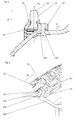
- FIG. 1 schematically shows a flange connection with a plurality of clamping devices according to the present invention, which connect a first component 100 and a second component 200 with each other.
- a front clamping device 10 in the illustration is shown in a longitudinal section.
- the components 100, 200 each have (in particular) a substantially cuboid flange web 110 or 210, which protrudes in a flange direction R from the respective component 100, 200.
- the flange webs each have three side surfaces angled relative to the respective component and a contact surface on which the flange webs 110, 210 are arranged adjacent to one another.
- the clamping device 10 is arranged locally in a section of a connecting edge of the first and second component 100, 200 and forms therefrom a frame 11, which in the illustration of FIG. 1 the two adjoining flange webs 110, 210 surrounded. He rotates the side and contact surfaces of the flange webs and crosses the connecting edge twice (not shown), in the perspective of the representation FIG. 1 namely once in front of and behind the flange webs 110, 210.
- the two flange webs 110, 210 pierce the frame 11;
- the illustrated frame surrounds the two flange webs along a frame plane which is substantially perpendicular to the piercing direction of the two flange webs provided by the flange direction R.
- the frame plane is angled relative to a contact surface of the two flange webs, in the example shown also by 90 °.
- the clamping device 10 furthermore has a bracing device, which in the example shown comprises a wedge screw 12 with a wedge 13 and a nut 15.
- the wedge screw 12 is guided through a through hole of a skirt 16 of the clamping device 10.
- the mounted on the wedge screw nut 15 braces the wedge 13 against the enclosure.
- a pressing surface 14 of the wedge 13 presses against the Flanschsteg 210.
- a tensioning force is exerted, which acts in the direction of the edged flange webs.
- the flange web 110 has a securing projection 111 on a side facing away from the remaining component 100 (that is, on an end face of the flange web 110).
- the frame is arranged in a section on the right side in the illustration between a component surface 101 of the component 100 and the securing projection 111 on the flange web.
- the wedge 13 has the same shape on the side facing the flange webs (on the right in the figure) as on the side facing away from the flange webs (on the left in the figure); in the illustrated longitudinal section of the wedge screw of the wedge 13 is therefore formed symmetrically to the screw axis A 1 , which is angled relative to the pressing surface 14 (ie not in a plane parallel to the pressing surface).
- the symmetrical design of the wedge allows a balanced balance of forces of screw and clamping force of the bracing device and thus a particularly solid connection of the two flange webs 110, 210th
- the two flange webs 110, 210 are connected to an alternative embodiment of a clamping device 20 according to the invention.
- the clamping device 20 also forms a frame 21, which surrounds the flange webs 110, 210 and is thereby punctured by them.
- the clamping device 20 also has a bracing device comprising a wedge screw 22 and a nut 25.
- a pressing surface 24 of the wedge 23 of the wedge screw 22 presses against the flange web 210.
- the bracing direction runs parallel to the pressing surface 24.
- components can be interconnected in which a diagonally oriented nut would be problematic because of the geometric configuration of the components.
- FIG. 3 an alternative flange connection according to an embodiment of the present invention is shown.
- the flange web 210 of the component 200 is here connected by means of a clamping device 30 with an inwardly angled flange web 310 of a component 300.
- the clamping device 30 forms a frame 31 which the flange webs 210 and 310 pierce; a base portion of a frame portion facing the connected components comprises two parallel, rectangular portions which are connected by a central surface arranged perpendicular to these two portions.
- the frame thus frames the flange web 210 and a first portion of the flange web 310; a second, angled portion of the flange web 310 forms an overhang over the other flange web 210 and a mount 311 for the tensioning device of the clamping device 30.
- this tensioning device comprises a tension screw 32 and a tensioning wedge 33, which presses against the flange web 210 in the tensioned state with a pressing surface 34.
- the clamping device is particularly well secured against slipping.
- a flange connection is shown in a first perspective view.
- the flange connection comprises a plurality of clamping devices 10, 10a, 10b arranged side by side along a connecting edge 400 of a first and second component 100, 200, in accordance with FIG FIG. 1 shown embodiment, each forming a frame 11, 11a.
- the frame 11a of the clamping device 10a extends along a frame plane E, which is perpendicular to a flange, in which the frame 11a rimmed flange webs protrude from the respective component and in which they pierce the frame.
- a base surface facing the connected components of a portion of the frame which lies in the frame plane E comprises two parallel, rectangular sections which are connected by a central surface arranged perpendicular to these two sections.
- the flange webs are in the in FIG. 4 illustrated embodiment, each similarly shaped.
- the flange webs 110, 110a, 110b each have an extension d 2 .
- Adjacent flange webs 110a, 110b of a component are each spaced apart by a distance d 1 .
- d 1 is at most twice as large as d 2 , more preferably at most one and a half times as large, or substantially the same size as d 2 , as is the case in particular in FIG FIG. 4 illustrated exemplary embodiment is the case.
- a substantially cylindrically shaped threaded portion of the wedge screw 12 has a diameter D.
- the respective extent d 2 of the individual flange webs 110, 110 a, 110 b is preferably at most twice, more preferably at most 1.5 times as large as a diameter of a substantially cylindrically shaped threaded part of a screw of the bracing device.
- FIG. 5 is the arrangement of FIG. 4 shown from a different perspective.
- the wedges 13 of the wedge screw in the illustrated embodiment each have a square base.
Landscapes
- Engineering & Computer Science (AREA)
- General Engineering & Computer Science (AREA)
- Mechanical Engineering (AREA)
- Clamps And Clips (AREA)
- Flanged Joints, Insulating Joints, And Other Joints (AREA)
- Mutual Connection Of Rods And Tubes (AREA)
- Connection Of Plates (AREA)
Abstract
Description
- Die vorliegende Erfindung betrifft eine Klemmvorrichtung zum Verbinden zweier aneinander anliegender Flanschstege von Bauteilen, und eine Flanschverbindung mit einer Klemmvorrichtung.
- Bauteile, die als Komponenten dazu vorgesehen sind, mit anderen Bauteilen zusammengesetzt zu werden, werden häufig mit Flanschen hergestellt. Ein Flansch (bzw. Flanschsteg) eines Bauteils bildet dabei eine Kontaktfläche aus, an der ein anderes Bauteil z.B. verschraubt, verklemmt oder festgeschweißt werden kann und die in vielen Anwendungen auch einer Kraftübertragung und/oder einer Abdichtung dient. Insbesondere können die zu verbindenden Bauteile gleichartige Flansche aufweisen, die bei einer Montage aneinander positioniert und miteinander verbunden werden können.
- Derartige Flanschverbindungen finden in vielfältigen Bereichen Anwendung. Mit ihnen können beispielsweise zusammengesetzte Rohre oder Gehäuse hergestellt werden, oder es können verschiedenartige Elemente, wie z.B. ein Motor und ein Gehäuse, aneinander befestigt werden.
- In herkömmlichen Flanschverbindungen verwendete Flansche weisen zumeist Durchgangsbohrungen auf. Durch diese Bohrungen werden Schrauben hindurchgeführt und mit Muttern verspannt. Hierbei liegen die Schrauben im Betriebskraftfluss und bestimmen die volle Klemmkraft.
- Ein alternatives Verbindungskonzept sieht vor, Flansche mit Hilfe von Keilelementen zu verklemmen. Dabei kann eine Schraube zur Fixierung des Keilelements verwendet werden.
- Beispielsweise offenbart die Druckschrift
DE 10 159 667 A1 eine Verbindungsvorrichtung zur lösbaren Verbindung zweier Bauteile, von denen eine im Wesentlichen zylindrische Ausnehmung eines ersten der Bauteile und ein im Wesentlichen zylindrischer Ansatz eines zweiten der Bauteile miteinander verspannt werden. - Aus der
US 2013/0039749 A1 sind ein Verfahren und eine Vorrichtung zum Ausrichten eines inneren Turbinengehäuses in Bezug auf ein äußeres Turbinengehäuse bekannt. - Die Druckschrift
DE 196 04 702 offenbart eine kraft- und formschlüssige Verbindungsanordnung für rotationssymmetrische Bauteile, bei der eine Hülse zwei aneinander anstoßende Flanschbunde übergreift. Mit Hilfe von Zugschrauben werden keilförmige Spannelemente in die Hülse hineingezogen. Die Spannelemente werden dadurch gegen einen der Bunde gepresst. Je nach Art der zu verbindenden Bauteile kann die Positionierung und Montage einer derartigen Verbindungsanordnung jedoch aufwendig sein. - Gemäß einer ebenfalls in der Druckschrift offenbarten Ausführungsform ist die Hülse an dem einen der beiden Bauteile ausgebildet. Auf eine derartig in das Bauteil integrierte Hülse, die über den anliegenden Flansch des anderen Bauteils hinübergreift, wirken durch die Verspannung und bei entsprechender Verwendung der verbundenen Bauteile hohe Biegekräfte, durch die das Material beansprucht und die Verbindung gelockert werden kann.
- Ähnliches gilt für eine in der Druckschrift
DE 10 2012 007 145 A1 offenbarte lösbare Verbindung von rotationssymmetrischen Bauteilen, die eine Hülse umfasst, die zwei aneinanderliegende Flanschbunde axial übergreift. - Die vorliegende Erfindung hat die Aufgabe, eine Technik zum Verbinden von Flanschstegen bereitzustellen, mit der die vorgenannten Nachteile überwunden werden können.
- Die Aufgabe wird gelöst durch eine Klemmvorrichtung gemäß Anspruch 1 und eine Flanschverbindung gemäß Anspruch 6. Bevorzugte Ausführungsformen sind in den Unteransprüchen offenbart.
- Eine Klemmvorrichtung gemäß der vorliegenden Erfindung dient einem Verbinden zweier aneinander anliegender Flanschstege zweier Bauteile, also dem Verbinden eines ersten Flanschsteges eines ersten Bauteils mit einem zweiten Flanschsteg eines zweiten Bauteils, wobei die Flanschstege aneinander anliegend positioniert sind. Die Klemmvorrichtung bildet einen Rahmen aus, der dazu eingerichtet bzw. geeignet ist, von den beiden aneinander anliegenden Flanschstegen durchstoßen zu werden; auf diese Weise umrandet der Rahmen die beiden Flanschstege.
- Die Klemmvorrichtung weist weiterhin eine Verspannungsvorrichtung auf, die dazu eingerichtet ist, die beiden aneinander anliegenden Flanschstege im Rahmen zu verspannen.
- Eine erfindungsgemäße Flanschverbindung verbindet ein erstes mit einem zweiten Bauteil. Das erste Bauteil weist dabei mindestens einen ersten Flanschsteg auf, der an einem zweiten Flanschsteg des zweiten Bauteils anliegt. Der erste und der zweite Flanschsteg durchstoßen einen Rahmen einer erfindungsgemäßen Klemmvorrichtung.
- Bei dem ersten und dem zweiten Bauteil handelt es sich vorzugsweise um zwei Gehäusebauteile einer Strömungsmaschine, insbesondere einer Fluggasturbine oder einer stationären Industuegasturbine. Vorzugsweise sind die beiden Gehäusebauteile in Umfangsrichtung nicht segmentiert ausgebildet. Ferner sind die beiden Bauteile im montierten Zustand der Strömungsmaschine vorzugsweise konzentrisch zur Maschinenachse der Strömungsmaschine angeordnet.
- Der Terminus "durchstoßen" ist in dieser Schrift vorzugsweise aber nicht zwingend so zu verstehen, dass die durchstoßenden Flanschstege vollständig durch den Rahmen ragen oder auf einer oder beiden Seiten des Rahmens aus diesem hervortreten müssen. Er bezieht sich insbesondere auf ein Verhältnis zwischen einer Rahmenebene, in der der Rahmen die Flanschstege umrandet (also umläuft), und einer (Durchstoß-)Richtung, in der die beiden Flanschstege in den Rahmen hineinragen (also den Rahmen durchstoßen): Diese Richtung und die Rahmenebene sind dabei gegeneinander abgewinkelt, vorzugsweise im Wesentlichen senkrecht zueinander angeordnet. Eine Durchstoßrichtung der Flanschstege entspricht vorzugsweise einer Flanschrichtung, also einer Richtung, in der die Flanschstege vom jeweiligen Bauteil abstehen.
- Mit Hilfe des umrandenden Rahmens können die Flanschstege somit mittels einer erfindungsgemäßen Klemmvorrichtung (bzw. in einer erfindungsgemäßen Flanschverbindung) fest miteinander verbunden werden, ohne dass Biegemomente erzeugt werden. Zudem wird die Verspannungsvorrichtung lediglich auf Zug belastet. Insbesondere bei verbundenen Bauteilen, die äußeren Belastungen, wie beispielsweise Einwirkungen hebelnder Kräfte, standhalten müssen, gewährleistet eine erfindungsgemäße Klemmvorrichtung daher eine dauerhaft stabile Verbindung.
- Der Rahmen kann mindestens in einem Abschnitt eine Grundfläche aufweisen, die dazu vorgesehen ist, im verspannten Zustand der Klemmvorrichtung den verbundenen Bauteilen zugewandt angeordnet zu liegen oder sogar auf mindestens einem der Bauteile aufzuliegen. Die Grundfläche kann einen Außenrand mit einem oder mehreren polygonförmigen (z.B. rechtwinkligen) oder geschwungenen Abschnitt(en) aufweisen. Vorzugsweise liegt die Grundfläche senkrecht zur Flanschrichtung und/oder senkrecht zu einer Kontaktfläche von erstem und zweitem Flanschsteg. Insbesondere kann die Grundfläche eine Rahmenebene definieren, in der die Grundfläche liegt.
- Die Flanschstege sind vorzugsweise im Wesentlichen quaderförmig oder umfassen zumindest einen quaderförmigen Abschnitt.
- Vorzugsweise liegen das erste und das zweite Bauteil entlang einer Verbindungskante aneinander an und kreuzt der Rahmen beim Umranden der Flanschstege mindestens zweimal die Verbindungskante der Bauteile.
- Die Verspannungsvorrichtung kann eine Schraube und einen mit der Schraube positionierbaren Keil umfassen. Der Keil ist dabei dazu eingerichtet, beim Verspannen in eine Verspannungsrichtung getrieben oder gezogen zu werden; die Verspannungsrichtung stimmt dabei vorzugsweise mit einer Schraubachse der Schraube überein. Gemäß einer bevorzugten Ausführungsform weist ein Innenumfang des Rahmens in einem verspannten Zustand einen Durchmesser auf, der höchstens dreimal, bevorzugter höchstens doppelt, noch bevorzugter höchstens 1,5 mal oder im Wesentlichen genauso so groß ist wie ein Durchmesser eines im Wesentlichen zylindrisch geformten Gewindeteils einer Schraube der Verspannungsvorrichtung. Diese Größenverhältnisse bieten den Vorteil einer besonders gleichmäßigen Krafteinwirkung der Verspannungsvorrichtung.
- Insbesondere kann die Verspannungsvorrichtung einen Spannkeil und eine Zugschraube aufweisen, mit welcher der Spannkeil durch eine Einfassung in der Klemmvorrichtung hindurch angezogen werden kann, um die beiden Flanschstege miteinander zu verspannen.
- Besonders bevorzugt ist eine Ausführungsform, bei der die Verspannungsvorrichtung einen Keilbolzen umfasst. Insbesondere kann die Verspannungsvorrichtung eine Keilschraube und eine Mutter umfassen. Beispielsweise kann bei einem Anziehen der Mutter der Keil der Keilschraube in ein (z.B. sich verengendes) Gehäuse gezogen und so die Spannung hergestellt werden. Insbesondere können die beiden Flanschstege gemäß dieser Ausführungsform somit durch Anziehen oder Lösen der Mutter miteinander verspannt bzw. voneinander gelöst werden. Die Verwendung einer Keilschraube, auf die zum Verspannen lediglich die Mutter aufgeschraubt werden muss, gewährleistet eine besonders einfach zu realisierende Verbindung und Montage.
- Gemäß einer bevorzugten Ausführungsform einer erfindungsgemäßen Klemmvorrichtung umfasst die Verspannungsvorrichtung einen Keil mit einer Pressfläche, die dazu eingerichtet ist, beim Verspannen der Flanschstege gegen einen der beiden aneinander anliegenden Flanschstege zu drücken.
- Aufgrund des unmittelbaren Angreifens an den einen der Flanschstege weist ein Klemmelement mit einer derartigen Verspannungsvorrichtung eine besonders günstige Kraftübertragung auf und gewährleistet damit ein verlustarmes Verspannen.
- Gemäß einer Ausführungsform einer erfindungsgemäßen Klemmvorrichtung erstreckt sich eine derartige Pressfläche in eine Richtung (parallel) zu einer Verspannungsrichtung des Keils, liegt also in einer Ebene, die einen Richtungsvektor in die Richtung hat, in die der Keil zum Verspannen gezogen oder getrieben werden kann; in einer Ausführungsform, bei der das Verspannungselement eine Keilschraube umfasst, erstreckt sich die Pressfläche somit vorzugsweise in Richtung (parallel zu) einer Schraubachse der Keilschraube. Deren Keil kann somit eine einseitige Schräge an lediglich einer den Flanschstegen abgewandten Seite aufweisen.
- Eine derartige Ausführungsform kann je nach einer geometrischen Ausgestaltung der beiden zu verbindenden Bauteile oder ihrer Flanschstege vorteilhaft sein. Insbesondere erlaubt sie eine Ausrichtung der Klemmvorrichtung, bei der eine Schraubachse einer den Keil anziehenden Zugschraube oder einer auf einer Keilschraube verschraubten Mutter parallel zu einer Flanschrichtung angeordnet und somit gegebenenfalls gut zugänglich ist.
- Gemäß einer bevorzugten Ausführungsform ist der Keil an einer den Flanschstegen zugewandten Seite im Wesentlichen ebenso geformt wie an einer den Flanschstegen abgewandten Seite; beispielsweise kann eine Pressfläche in Bezug auf eine Schraubachse (einer Keilschraube, die den Keil ausbildet, oder einer Zugschraube, die den Keil anzieht) in gleichem Winkel geneigt ausgebildet sein wie eine den Flanschstegen abgewandte Oberfläche des Keils. Insbesondere kann ein derartiger Keil einen Längsschnitt entlang einer Schraubachse (einer Keilschraube, die den Keil ausbildet, oder einer Zugschraube, die den Keil anzieht) aufweisen, der symmetrisch zur Schraubachse ausgebildet ist; alternativ oder zusätzlich kann der Keil mindestens einen Querschnitt orthogonal zur Schraubachse aufweisen, der punktsymmetrisch zu einem Durchstoßpunkt der Schraubachse ist; besonders bevorzugt ist eine Ausführungsform, bei der jeder derartige Querschnitt derart punktsymmetrisch ist (z.B. rechteckig, insbesondere quadratisch).
- Eine solche gleichartige geometrische Form des Keils an der den Flanschstegen zugewandten Seite und der den Flanschstegen abgewandten Seite (zwischen denen beispielsweise die Schraubachse der Keilschraube oder der Zugschraube angeordnet sein kann) ermöglicht ein besonders ausgewogenes Kräfteverhältnis von Schraub- und Klemmkraft der Verspannungsvorrichtung. Ungleichmäßige Kräfte in der Verspannung werden somit vermieden, wodurch die Klemmung besonders solide ausgebildet werden kann.
- Gemäß einer Ausführungsform einer erfindungsgemäßen Flanschverbindung umfasst ein erster der Flanschstege mindestens einen Sicherungsvorsprung an einer vom Bauteil abgewandten Seite. Der Rahmen der Klemmvorrichtung ist dabei mindestens in einem Abschnitt zwischen einer Bauteiloberfläche, von welcher der erste Flanschsteg absteht, und dem mindestens einen Sicherungsvorsprung am Flanschsteg angeordnet. Ein derartiger Sicherungsvorsprung kann beispielsweise als ein Steg ausgebildet sein. Er verhindert ein Abrutschen der Klemmvorrichtung von den durch sie miteinander verspannten Flanschstegen, dient also einer Sicherung der Flanschverbindung.
- Gemäß einer bevorzugten Ausführungsform der vorliegenden Erfindung umfasst die Klemmvorrichtung eine Einfassung mit einer Durchgangsbohrung für die Verspannungsvorrichtung. Durch die Einfassung kann beispielsweise eine Keilschraube der eine Zugschraube der Verspannungsvorrichtung geführt sein; dabei sind vorzugsweise ein Keil der Keilschraube und eine Mutter auf der Keilschraube bzw. ein der Zugschraube anzuziehender Keil und ein Kopf der Zugschraube an voneinander verschiedenen Seiten der Einfassung angeordnet. Vorzugsweise ist eine derartige Einfassung einteilig mit dem Rahmen ausgebildet. Dadurch kann eine besonders gute Stabilität der Klemmvorrichtung auch bei großer Spannung der Spannungsvorrichtung gewährleistet werden.
- Alternativ oder zusätzlich kann in einer erfindungsgemäßen Flanschverbindung einer der Flanschstege eine Einfassung mit einer Durchgangsbohrung für die Verspannungsvorrichtung aufweisen. Analog zum Obigen kann durch die Einfassung in dem Flanschsteg beispielsweise eine Keilschraube der Verspannungsvorrichtung geführt sein; dabei sind vorzugsweise ein Keil der Keilschraube und eine Mutter auf der Keilschraube bzw. ein der Zugschraube anzuziehender Keil und ein Kopf der Zugschraube an voneinander verschiedenen Seiten der Einfassung angeordnet.
- Ein derartiger Flanschsteg ist vorzugsweise in sich abgewinkelt ausgebildet mit einem ersten Abschnitt, der durch den Rahmen der Klemmverbindung verläuft, und einem zweiten Abschnitt, der einen Überhang über den zweiten Flanschsteg ausbildet und die Einfassung für die Verspannungsvorrichtung ausbildet.
- Bei dieser Ausführungsform ist der eine Flanschsteg mit der Klemmvorrichtung verschraubt, was eine besonders gute Sicherung der Flanschverbindung gegen ein Abrutschen der Klemmvorrichtung bedeutet.
- Vorteilhaft ist eine Ausführungsform, bei der das erste und das zweite mittels der Flanschverbindung verbundene Bauteil entlang einer Verbindungskante der beiden Bauteile aneinander anstoßen, wobei das erste und das zweite Bauteil entlang der Verbindungskante eine Mehrzahl an (vorzugsweise gleichartigen) Flanschstegen aufweisen. Ein Abstand zwischen zwei benachbarten Flanschstegen desselben Bauteils beträgt dabei vorzugsweise jeweils höchstens das Doppelte, bevorzugter höchstens das 1,5-fache einer Ausdehnung eines Flanschsteges entlang (also parallel zur Richtung) der Verbindungskante; noch bevorzugter sind der genannte Abstand und die genannte Ausdehnung im Wesentlichen gleich groß. Die Flanschstege des ersten Bauteils sind vorzugsweise jeweils mittels einer Klemmvorrichtung gemäß einer Ausführungsform der vorliegenden Erfindung mit einem Flanschsteg des zweiten Bauteils verbunden.
- Die genannten Abstände gewährleisten eine sichere und dichte Verbindung der beiden Bauteile, indem nicht miteinander verspannte Abschnitte gegenüber miteinander verspannten Abschnitten die angegebene, relativ geringe Ausdehnung haben. Dies ist beispielsweise besonders vorteilhaft, wenn die Verbindung der beiden Bauteile gegen einen Fluiddurchlass abgedichtet sein soll.
- Im Folgenden werden bevorzugte Ausführungsbeispiele der Erfindung anhand von Zeichnungen näher erläutert. Es versteht sich, dass einzelne Elemente und Komponenten auch anders kombiniert werden können als dargestellt.
- Es zeigen schematisch:
- Figur 1
- eine Flanschverbindung mit Klemmvorrichtung gemäß einer beispielhaften Ausführungsform der vorliegenden Erfindung;
- Figur 2
- eine Flanschverbindung eine Klemmvorrichtung gemäß einer alternativen Ausführungsform der vorliegenden Erfindung;
- Figur 3
- eine Flanschverbindung eine Klemmvorrichtung gemäß einer weiteren alternativen Ausführungsform der vorliegenden Erfindung;
- Figur 4
- eine Flanschverbindung gemäß
Figur 1 in einer ersten perspektivischen Ansicht; - Figur 5
- eine Flanschverbindung gemäß
Figur 1 in einer zweiten perspektivischen Ansicht. -
Figur 1 zeigt schematisch eine Flanschverbindung mit mehreren Klemmvorrichtungen gemäß der vorliegenden Erfindung, die ein erstes Bauteil 100 und ein zweites Bauteil 200 miteinander verbinden. Zur Kenntlichmachung eines inneren Aufbaus der Klemmvorrichtung ist eine in der Darstellung vorderste Klemmvorrichtung 10 in einem Längsschnitt gezeigt. - Die Bauteile 100, 200 weisen jeweils (insbesondere) einen im Wesentlichen quaderförmigen Flanschsteg 110 bzw. 210 auf, der in eine Flanschrichtung R vom jeweiligen Bauteil 100, 200 absteht. Insbesondere weisen die Flanschstege jeweils drei gegenüber dem jeweiligen Bauteil abgewinkelte Seitenflächen und eine Kontaktfläche auf, an der die Flanschstege 110, 210 aneinander anliegend angeordnet sind.
- Die Klemmvorrichtung 10 ist lokal in einem Abschnitt einer Verbindungskante von erstem und zweitem Bauteil 100, 200 angeordnet und bildet dort einen Rahmen 11 aus, der in der Darstellung der
Figur 1 die beiden aneinander anliegenden Flanschstege 110, 210 umrandet. Dabei umläuft er die Seiten- und Kontaktflächen der Flanschstege und kreuzt die Verbindungskante zweimal (nicht dargestellt), in der Darstellungsperspektive derFigur 1 nämlich je einmal vor und hinter den Flanschstegen 110, 210. - Die beiden Flanschstege 110, 210 durchstoßen den Rahmen 11; insbesondere umrandet der dargestellte Rahmen die beiden Flanschstege entlang einer Rahmenebene, die im Wesentlichen senkrecht zur durch die Flanschrichtung R gegebenen Durchstoßrichtung der beiden Flanschstege liegt. Zudem ist die Rahmenebene gegenüber einer Kontaktfläche der beiden Flanschstege abgewinkelt, im dargestellten Beispiel ebenfalls um 90°.
- Die Klemmvorrichtung 10 weist weiterhin eine Verspannungsvorrichtung auf, die im gezeigten Beispiel eine Keilschraube 12 mit Keil 13 sowie eine Mutter 15 umfasst. Die Keilschraube 12 ist durch eine Durchgangsbohrung einer Einfassung 16 der Klemmvorrichtung 10 geführt. Die auf die Keilschraube aufgezogene Mutter 15 verspannt den Keil 13 gegen die Einfassung. Dabei drückt eine Pressfläche 14 des Keils 13 gegen den Flanschsteg 210. Dadurch wird eine Verspannungskraft ausgeübt, die in Richtung der umrandeten Flanschstege wirkt.
- Der Flanschsteg 110 weist an einer dem übrigen Bauteil 100 abgewandten Seite (also an einer Stirnfläche des Flanschstegs 110) einen Sicherungsvorsprung 111 auf. Der Rahmen ist in einem Abschnitt an der in der Darstellung rechten Seite zwischen einer Bauteiloberfläche 101 des Bauteils 100 und dem Sicherungsvorsprung 111 am Flanschsteg angeordnet. Dadurch ist die Klemmvorrichtung 10 gegen ein Abrutschen von den aneinander anliegenden Flanschstegen gesichert.
- In dem in
Figur 1 gezeigten Ausführungsbeispiel weist der Keil 13 an der den Flanschstegen zugewandten (in der Figur rechten) Seite die gleiche Form auf wie an der den Flanschstegen abgewandten (in der Figur linken) Seite; im dargestellten Längsschnitt der Keilschraube ist der Keil 13 daher symmetrisch zur Schraubachse A1 ausgebildet, die gegenüber der Pressfläche 14 abgewinkelt ist (also nicht in einer Ebene parallel zur Pressfläche verläuft). - Die symmetrische Ausbildung des Keils ermöglicht ein ausgewogenes Kräfteverhältnis von Schraub- und Klemmkraft der Verspannungsvorrichtung und damit eine besonders solide Verbindung der beiden Flanschstege 110, 210.
- In der
Figur 2 sind die beiden Flanschstege 110, 210 mit einer alternativen Ausführungsform einer erfindungsgemäßen Klemmvorrichtung 20 verbunden. Analog zur Klemmvorrichtung 10 bildet auch die Klemmvorrichtung 20 einen Rahmen 21 aus, der die Flanschstege 110, 210 umrandet und dabei von ihnen durchstoßen wird. Die Klemmvorrichtung 20 weist zudem eine Verspannungsvorrichtung auf, die eine Keilschraube 22 und eine Mutter 25 umfasst. Eine Pressfläche 24 des Keils 23 der Keilschraube 22 drückt dabei gegen den Flanschsteg 210. Beim Verspannen der Mutter auf der Keilschraube wird deren Keil 23 in eine Verspannungsrichtung parallel zu einer Schraubachse A2 gezogen. Die Verspannungsrichtung verläuft dabei parallel zur Pressfläche 24. - Aufgrund dieser Ausführung ist es möglich, die Klemmvorrichtung 20 so auf die aneinander anliegenden Flanschstege 110, 210 aufzusetzen, dass die Schraubachse A2 parallel zur Flanschrichtung R verläuft. Insbesondere ist die Klemmvorrichtung gegenüber den Flanschstegen daher nicht geneigt.
- Dadurch können beispielsweise Bauteile miteinander verbunden werden, bei denen eine schräg ausgerichtete Mutter wegen der geometrischen Ausgestaltung der Bauteile problematisch wäre.
- In
Figur 3 ist eine alternative Flanschverbindung gemäß einer Ausführungsform der vorliegenden Erfindung dargestellt. Der Flanschsteg 210 des Bauteils 200 ist hier mittels einer Klemmvorrichtung 30 mit einem in sich abgewinkelten Flanschsteg 310 eines Bauteils 300 verbunden. Die Klemmvorrichtung 30 bildet einen Rahmen 31, den die Flanschstege 210 und 310 durchstoßen; eine den verbundenen Bauteilen zugewandte Grundfläche eines Rahmenabschnitts umfasst zwei parallele, rechteckige Abschnitte, die von einer senkrecht zu diesen beiden Abschnitten angeordneten Mittelfläche verbunden werden. - Der Rahmen umrandet auf diese Weise den Flanschsteg 210 sowie einen ersten Abschnitt des Flanschstegs 310; ein zweiter, abgewinkelter Abschnitt des Flanschstegs 310 bildet einen Überhang über den anderen Flanschsteg 210 und eine Einfassung 311 für die Spannungsvorrichtung der Klemmvorrichtung 30 aus. Diese Spannungsvorrichtung umfasst im dargestellten Beispiel eine Zugschraube 32 und einen Spannkeil 33, der im verspannten Zustand mit einer Pressfläche 34 gegen den Flanschsteg 210 drückt.
- Bei einer derartigen Ausführungsform ist die Klemmvorrichtung besonders gut gegen ein Abrutschen gesichert.
- In
Figur 4 ist eine Flanschverbindung in einer ersten perspektivischen Ansicht dargestellt. Die Flanschverbindung umfasst dabei eine Mehrzahl an nebeneinander entlang einer Verbindungskante 400 eines ersten und zweiten Bauteils 100, 200 angeordneten Klemmvorrichtungen 10, 10a, 10b entsprechend der inFigur 1 gezeigten Ausführungsform, die jeweils einen Rahmen 11, 11a ausbilden. - Beispielsweise der Rahmen 11a der Klemmvorrichtung 10a verläuft dabei entlang einer Rahmenebene E, die senkrecht zu einer Flanschrichtung liegt, in der die vom Rahmen 11a umrandeten Flanschstege vom jeweiligen Bauteil abstehen und in der sie den Rahmen durchstoßen. Eine den verbundenen Bauteilen zugewandte Grundfläche eines Abschnitts des Rahmens, die in der Rahmenebene E liegt, umfasst zwei parallele, rechteckige Abschnitte, die von einer senkrecht zu diesen beiden Abschnitten angeordneten Mittelfläche verbunden werden.
- Die Flanschstege sind in der in
Figur 4 dargestellten Ausführungsform jeweils gleichartig geformt. Entlang der Verbindungskante 400 (und in Richtung der Verbindungskante) haben die Flanschstege 110, 110a, 110b jeweils eine Ausdehnung d2. Benachbarte Flanschstege 110a, 110b eines Bauteils sind dabei jeweils um einen Abstand d1 voneinander beabstandet. Vorzugsweise ist dabei d1 maximal doppelt so groß wie d2, noch bevorzugter maximal anderthalb mal so groß oder im Wesentlichen genauso groß wie d2, wie es insbesondere in der inFigur 4 dargestellten beispielhaften Ausführungsform der Fall ist. Diese Abstände gewährleisten eine besonders gute Dichtheit der verbundenen Bauteile. - Wie ebenfalls in der
Figur 4 gezeigt ist, weist ein im Wesentlichen zylindrisch geformter Gewindeteil der Keilschraube 12 einen Durchmesser D auf. Die jeweilige Ausdehnung d2 der einzelnen Flanschstege 110, 110a, 110b ist vorzugsweise höchstens doppelt, noch bevorzugter höchstens 1,5 mal so groß ist wie ein Durchmesser eines im Wesentlichen zylindrisch geformten Gewindeteils einer Schraube der Verspannungsvorrichtung. Diese Größenverhältnisse bieten den Vorteil einer besonders gleichmäßigen Krafteinwirkung der Verspannungsvorrichtung. - In
Figur 5 ist die Anordnung derFigur 4 aus einer anderen Perspektive gezeigt. Wie in der Figur ersichtlich, haben die Keile 13 der Keilschraube in der dargestellten Ausführungsform jeweils eine quadratische Grundfläche. Insbesondere ist in dieser Ausführungsform jeder in einer Ebene orthogonal zur Schraubachse A1 verlaufende Querschnitt der Keile 13 punktsymmetrisch zu einem Durchstoßpunkt P der Schraubachse A1. -
- 10, 20
- Klemmvorrichtung
- 11a, 11b, 21, 31
- Rahmen
- 12, 22
- Keilschraube
- 13
- Keil
- 14, 24, 34
- Pressfläche
- 15, 25
- Mutter
- 16
- Einfassung
- 32
- Zugschraube
- 33
- Spannkeil
- 100, 200, 300
- Bauteil
- 101
- Bauteiloberfläche
- 110, 110a, 110b, 210, 310
- Flanschsteg
- 111
- Sicherungsvorsprung
- 311
- Einfassung
- 400
- Verbindungskante
- A1, A2
- Schraubenachse
- d1
- Abstand zwischen zwei benachbarten Flanschstegen
- d2
- Erstreckung eines Flanschstegs
- E
- Rahmenebene
- D
- Durchmesser einer Keilschraube
- P
- Durchstoßpunkt
- R
- Flanschrichtung
Claims (10)
- Klemmvorrichtung (10, 10a, 10b, 20, 30) zum Verbinden zweier aneinander anliegender Flanschstege (110, 210, 310) von Bauteilen,
wobei die Klemmvorrichtung einen Rahmen (11, 21, 31) ausbildet, der dazu eingerichtet ist, von den beiden aneinander anliegenden Flanschstegen durchstoßen zu werden;
und wobei die Klemmvorrichtung eine Verspannungsvorrichtung (12, 13, 22, 23, 32, 33) umfasst, die dazu eingerichtet ist, die beiden aneinander anliegenden Flanschstege im Rahmen zu verspannen. - Klemmvorrichtung gemäß Anspruch 1, wobei die Verspannungsvorrichtung einen Keil (13, 23, 33) mit einer Pressfläche (14, 24, 34) umfasst, die dazu eingerichtet ist, beim Verspannen der Flanschstege gegen einen (210) der beiden aneinander anliegenden Flanschstege zu drücken.
- Klemmvorrichtung gemäß Anspruch 2, wobei der Keil dazu eingerichtet ist, beim Verspannen in eine Verspannungsrichtung getrieben oder gezogen zu werden, und wobei die Pressfläche (24) sich parallel zur Verspannungsrichtung erstreckt.
- Klemmvorrichtung gemäß einem der vorherigen Ansprüche, wobei der Keil an einer den Flanschstegen zugewandten Seite und an einer den Flanschstegen abgewandten Seite im Wesentlichen gleichartig geformt ist.
- Klemmvorrichtung gemäß einem der vorherigen Ansprüche, wobei die Verspannungsvorrichtung eine Keilschraube (22) und eine Mutter (25) umfasst.
- Klemmvorrichtung gemäß einem der vorherigen Ansprüche, die eine Einfassung (16) mit Durchgangsbohrung für die Verspannungsvorrichtung aufweist.
- Flanschverbindung eines ersten mit einem zweiten Bauteils, wobei das erste Bauteil (100) mindestens einen ersten Flanschsteg (110) aufweist, der in der Flanschverbindung an einem zweiten Flanschsteg (210) des zweiten Bauteils (200) anliegt, und wobei die Flanschverbindung eine Klemmvorrichtung (10, 10a, 10b, 20, 30) gemäß einem der Ansprüche 1 bis 6 aufweist, deren Rahmen der erste und der zweite Flanschsteg durchstoßen.
- Flanschverbindung gemäß Anspruch 7, wobei der Rahmen mindestens in einem Abschnitt zwischen einer Bauteiloberfläche (101), von der einer der Flanschstege (110) absteht, und einem Sicherungsvorsprung (111) am Flanschsteg angeordnet ist.
- Flanschverbindung gemäß Anspruch 7, wobei der erste Flanschsteg eine Einfassung (311) für die Verspannungsvorrichtung ausbildet.
- Flanschverbindung gemäß einem der Ansprüche 7 bis 9, wobei das erste und das zweite Bauteil jeweils entlang einer Verbindungskante (400) eine Mehrzahl an Flanschstegen aufweisen, wobei ein Abstand (d1) zwischen zwei benachbarten Flanschstegen jeweils maximal das Doppelte einer Ausdehnung (d2) eines Flanschsteges entlang der Verbindungskante beträgt oder diese Ausdehnung (d2) im Wesentlichen entspricht.
Applications Claiming Priority (1)
| Application Number | Priority Date | Filing Date | Title |
|---|---|---|---|
| DE102015209568.1A DE102015209568B4 (de) | 2015-05-26 | 2015-05-26 | Flanschverbindung mit einer Klemmvorrichtung zum Verbinden von Flanschstegen |
Publications (2)
| Publication Number | Publication Date |
|---|---|
| EP3101240A1 true EP3101240A1 (de) | 2016-12-07 |
| EP3101240B1 EP3101240B1 (de) | 2020-04-01 |
Family
ID=55910796
Family Applications (1)
| Application Number | Title | Priority Date | Filing Date |
|---|---|---|---|
| EP16167824.8A Active EP3101240B1 (de) | 2015-05-26 | 2016-04-29 | Klemmvorrichtung zum verbinden von flanschstegen |
Country Status (4)
| Country | Link |
|---|---|
| US (1) | US10584816B2 (de) |
| EP (1) | EP3101240B1 (de) |
| DE (1) | DE102015209568B4 (de) |
| ES (1) | ES2792862T3 (de) |
Families Citing this family (1)
| Publication number | Priority date | Publication date | Assignee | Title |
|---|---|---|---|---|
| DK181075B1 (en) | 2021-05-17 | 2022-11-22 | Stiesdal Offshore As | Method of connecting tubular members in offshore structures |
Citations (7)
| Publication number | Priority date | Publication date | Assignee | Title |
|---|---|---|---|---|
| DE19604702A1 (de) | 1995-11-25 | 1997-06-05 | Gutehoffnungshuette Man | Kraft- und formschlüssige Verbindung von rotationssymmetrischen Bauteilen |
| DE10159667A1 (de) | 2001-12-05 | 2003-06-18 | Rolls Royce Deutschland | Verbindungsvorrichtung |
| EP1995415A1 (de) * | 2007-05-24 | 2008-11-26 | Rolls-Royce plc | Abgaskanalanordnung für eine Gasturbine |
| EP2096272A1 (de) * | 2008-02-27 | 2009-09-02 | Siemens Aktiengesellschaft | Geteiltes Turbomaschinengehäuse mit optimierten Teilfugenflanschen |
| EP2336474A1 (de) * | 2009-12-16 | 2011-06-22 | OTLAV SpA | Klemme |
| US20130039749A1 (en) | 2011-08-12 | 2013-02-14 | Matthew Stephen Casavant | Methods and apparatus to facilitate turbine casing assembly |
| DE102012007145A1 (de) | 2012-04-12 | 2013-10-17 | Alfred W. Schlemenat | Lösbare Verbindung von rotationssymmetrischen Bauteilen |
Family Cites Families (12)
| Publication number | Priority date | Publication date | Assignee | Title |
|---|---|---|---|---|
| GB189524094A (en) * | 1895-12-16 | 1896-09-12 | Charles John Young | An Improved Joint for Taps, Pipes, and the like. |
| US1089859A (en) * | 1912-11-27 | 1914-03-10 | Haynes Automobile Company | Flexible coupling. |
| US1160462A (en) * | 1914-11-16 | 1915-11-16 | Cecil Hamelin Taylor | Shaft connection. |
| CH370604A (fr) * | 1961-09-14 | 1963-07-15 | Lapidor Sa | Dispositif d'assemblage d'éléments tubulaires, notamment pour la réalisation de canaux de ventilation |
| DE1252483B (de) * | 1962-02-01 | 1967-10-19 | Aktiebolaget Atomenergi Stockholm | Flanschverbindung fur Druckbehälter oder Rohre mit abwechselnd in entgegengesetzter Richtung geneigten Spannschrauben |
| US3744367A (en) * | 1970-05-06 | 1973-07-10 | L Lerich | Expansion bolt |
| US4243213A (en) * | 1979-01-18 | 1981-01-06 | Georgian Michael T | Adjustable precision grinding and machinist vise |
| EP0082319B1 (de) * | 1981-12-15 | 1986-10-15 | J. Weck GmbH & Co. | Verschlussanordnung für Einkochglas |
| US4519590A (en) * | 1983-01-05 | 1985-05-28 | Ford Motor Company | Axle clamp for filament reinforced synthetic material leaf springs |
| DE19857554A1 (de) * | 1998-12-14 | 2000-06-15 | Rolls Royce Deutschland | Verbindungsanordnung zweier Laufscheiben einer Axial-Strömungsmaschine |
| DE29921714U1 (de) | 1998-12-16 | 2000-03-09 | Schlemenat, Alfred, 45701 Herten | Lösbare Verbindung von rotationssymmetrischen Bauteilen |
| DE10342907A1 (de) * | 2003-09-17 | 2005-04-21 | Pfeiffer Vacuum Gmbh | Vakuumpumpe mit schnelldrehendem Rotor |
-
2015
- 2015-05-26 DE DE102015209568.1A patent/DE102015209568B4/de not_active Expired - Fee Related
-
2016
- 2016-04-29 EP EP16167824.8A patent/EP3101240B1/de active Active
- 2016-04-29 ES ES16167824T patent/ES2792862T3/es active Active
- 2016-05-16 US US15/155,976 patent/US10584816B2/en not_active Expired - Fee Related
Patent Citations (7)
| Publication number | Priority date | Publication date | Assignee | Title |
|---|---|---|---|---|
| DE19604702A1 (de) | 1995-11-25 | 1997-06-05 | Gutehoffnungshuette Man | Kraft- und formschlüssige Verbindung von rotationssymmetrischen Bauteilen |
| DE10159667A1 (de) | 2001-12-05 | 2003-06-18 | Rolls Royce Deutschland | Verbindungsvorrichtung |
| EP1995415A1 (de) * | 2007-05-24 | 2008-11-26 | Rolls-Royce plc | Abgaskanalanordnung für eine Gasturbine |
| EP2096272A1 (de) * | 2008-02-27 | 2009-09-02 | Siemens Aktiengesellschaft | Geteiltes Turbomaschinengehäuse mit optimierten Teilfugenflanschen |
| EP2336474A1 (de) * | 2009-12-16 | 2011-06-22 | OTLAV SpA | Klemme |
| US20130039749A1 (en) | 2011-08-12 | 2013-02-14 | Matthew Stephen Casavant | Methods and apparatus to facilitate turbine casing assembly |
| DE102012007145A1 (de) | 2012-04-12 | 2013-10-17 | Alfred W. Schlemenat | Lösbare Verbindung von rotationssymmetrischen Bauteilen |
Also Published As
| Publication number | Publication date |
|---|---|
| DE102015209568B4 (de) | 2017-07-06 |
| US20160348815A1 (en) | 2016-12-01 |
| US10584816B2 (en) | 2020-03-10 |
| EP3101240B1 (de) | 2020-04-01 |
| DE102015209568A1 (de) | 2016-12-01 |
| ES2792862T3 (es) | 2020-11-12 |
Similar Documents
| Publication | Publication Date | Title |
|---|---|---|
| EP3673181B1 (de) | Schnellverschraubung zum verbinden von mehrteiligen baugruppen | |
| EP3479002B1 (de) | Verfahren zum fügen von rohrstücken | |
| EP1396644A1 (de) | Vorrichtung zum Verbinden von Montageschienen | |
| DE102015118505B4 (de) | Befestigungsvorrichtung | |
| DE102015209568B4 (de) | Flanschverbindung mit einer Klemmvorrichtung zum Verbinden von Flanschstegen | |
| EP1583683A1 (de) | Anordnung zum verbinden eines rohrförmigen ersten bauteils mit einem zweiten bauteil | |
| EP3560809A1 (de) | Vorbau-verbindungseinrichtung sowie fahrrad-element | |
| EP2095004B1 (de) | Aggregat-anschlussvorrichtung für medienleitungen | |
| WO2013050171A1 (de) | Verbindungselement für ein tragrahmensystem | |
| DE69305423T2 (de) | Verkehrszeichen | |
| DE102012008748B4 (de) | Kettenlaschenpositionierhilfe, Kettentrenn- und -vernietwerkzeug sowie Verfahren zum Positionieren von Laschen und Bolzen einer Bolzen-Laschen-Kette | |
| DE102008035069B4 (de) | Kfz-Verbrennungsmotor-Ansauganordnung | |
| EP1507996A1 (de) | Rohrschelle | |
| DE102022127308B3 (de) | Verbindungsanordnung, Maschinengestell sowie Transportsystem | |
| EP3101318B1 (de) | Ventilmodul | |
| DE10105390C1 (de) | Plattenschieber | |
| EP2327886A1 (de) | Lösbare Verbindung zwischen einem Hohlprofil und einem weiteren Profil | |
| EP3640484A1 (de) | Verbindungsanordnung für mindestens zwei profilelemente | |
| DE202015107055U1 (de) | Kupplungselement | |
| EP1306280B1 (de) | Abstützelement bei einem Spannring | |
| DE3405631C2 (de) | ||
| DE1708005C (de) | Knotenpunktverbindung für Stahlrohrfachwerke | |
| DE202010006854U1 (de) | Verbindungssystem | |
| EP3517793A1 (de) | Rohrverbindungsvorrichtung | |
| DE112013002789T5 (de) | Halterung |
Legal Events
| Date | Code | Title | Description |
|---|---|---|---|
| PUAI | Public reference made under article 153(3) epc to a published international application that has entered the european phase |
Free format text: ORIGINAL CODE: 0009012 |
|
| STAA | Information on the status of an ep patent application or granted ep patent |
Free format text: STATUS: THE APPLICATION HAS BEEN PUBLISHED |
|
| AK | Designated contracting states |
Kind code of ref document: A1 Designated state(s): AL AT BE BG CH CY CZ DE DK EE ES FI FR GB GR HR HU IE IS IT LI LT LU LV MC MK MT NL NO PL PT RO RS SE SI SK SM TR |
|
| AX | Request for extension of the european patent |
Extension state: BA ME |
|
| STAA | Information on the status of an ep patent application or granted ep patent |
Free format text: STATUS: REQUEST FOR EXAMINATION WAS MADE |
|
| 17P | Request for examination filed |
Effective date: 20170601 |
|
| RBV | Designated contracting states (corrected) |
Designated state(s): AL AT BE BG CH CY CZ DE DK EE ES FI FR GB GR HR HU IE IS IT LI LT LU LV MC MK MT NL NO PL PT RO RS SE SI SK SM TR |
|
| RIC1 | Information provided on ipc code assigned before grant |
Ipc: F16B 2/14 20060101ALI20190920BHEP Ipc: F01D 25/24 20060101AFI20190920BHEP Ipc: F01D 25/26 20060101ALI20190920BHEP Ipc: F16B 5/06 20060101ALI20190920BHEP Ipc: F16B 35/06 20060101ALI20190920BHEP |
|
| GRAP | Despatch of communication of intention to grant a patent |
Free format text: ORIGINAL CODE: EPIDOSNIGR1 |
|
| STAA | Information on the status of an ep patent application or granted ep patent |
Free format text: STATUS: GRANT OF PATENT IS INTENDED |
|
| INTG | Intention to grant announced |
Effective date: 20191104 |
|
| GRAS | Grant fee paid |
Free format text: ORIGINAL CODE: EPIDOSNIGR3 |
|
| GRAA | (expected) grant |
Free format text: ORIGINAL CODE: 0009210 |
|
| STAA | Information on the status of an ep patent application or granted ep patent |
Free format text: STATUS: THE PATENT HAS BEEN GRANTED |
|
| AK | Designated contracting states |
Kind code of ref document: B1 Designated state(s): AL AT BE BG CH CY CZ DE DK EE ES FI FR GB GR HR HU IE IS IT LI LT LU LV MC MK MT NL NO PL PT RO RS SE SI SK SM TR |
|
| REG | Reference to a national code |
Ref country code: GB Ref legal event code: FG4D Free format text: NOT ENGLISH |
|
| REG | Reference to a national code |
Ref country code: CH Ref legal event code: EP Ref country code: AT Ref legal event code: REF Ref document number: 1251591 Country of ref document: AT Kind code of ref document: T Effective date: 20200415 |
|
| REG | Reference to a national code |
Ref country code: DE Ref legal event code: R096 Ref document number: 502016009342 Country of ref document: DE |
|
| REG | Reference to a national code |
Ref country code: IE Ref legal event code: FG4D Free format text: LANGUAGE OF EP DOCUMENT: GERMAN |
|
| REG | Reference to a national code |
Ref country code: DE Ref legal event code: R082 Ref document number: 502016009342 Country of ref document: DE |
|
| PG25 | Lapsed in a contracting state [announced via postgrant information from national office to epo] |
Ref country code: BG Free format text: LAPSE BECAUSE OF FAILURE TO SUBMIT A TRANSLATION OF THE DESCRIPTION OR TO PAY THE FEE WITHIN THE PRESCRIBED TIME-LIMIT Effective date: 20200701 |
|
| REG | Reference to a national code |
Ref country code: NL Ref legal event code: MP Effective date: 20200401 |
|
| REG | Reference to a national code |
Ref country code: LT Ref legal event code: MG4D |
|
| PG25 | Lapsed in a contracting state [announced via postgrant information from national office to epo] |
Ref country code: PT Free format text: LAPSE BECAUSE OF FAILURE TO SUBMIT A TRANSLATION OF THE DESCRIPTION OR TO PAY THE FEE WITHIN THE PRESCRIBED TIME-LIMIT Effective date: 20200817 Ref country code: NL Free format text: LAPSE BECAUSE OF FAILURE TO SUBMIT A TRANSLATION OF THE DESCRIPTION OR TO PAY THE FEE WITHIN THE PRESCRIBED TIME-LIMIT Effective date: 20200401 Ref country code: LT Free format text: LAPSE BECAUSE OF FAILURE TO SUBMIT A TRANSLATION OF THE DESCRIPTION OR TO PAY THE FEE WITHIN THE PRESCRIBED TIME-LIMIT Effective date: 20200401 Ref country code: FI Free format text: LAPSE BECAUSE OF FAILURE TO SUBMIT A TRANSLATION OF THE DESCRIPTION OR TO PAY THE FEE WITHIN THE PRESCRIBED TIME-LIMIT Effective date: 20200401 Ref country code: NO Free format text: LAPSE BECAUSE OF FAILURE TO SUBMIT A TRANSLATION OF THE DESCRIPTION OR TO PAY THE FEE WITHIN THE PRESCRIBED TIME-LIMIT Effective date: 20200701 Ref country code: SE Free format text: LAPSE BECAUSE OF FAILURE TO SUBMIT A TRANSLATION OF THE DESCRIPTION OR TO PAY THE FEE WITHIN THE PRESCRIBED TIME-LIMIT Effective date: 20200401 Ref country code: GR Free format text: LAPSE BECAUSE OF FAILURE TO SUBMIT A TRANSLATION OF THE DESCRIPTION OR TO PAY THE FEE WITHIN THE PRESCRIBED TIME-LIMIT Effective date: 20200702 Ref country code: IS Free format text: LAPSE BECAUSE OF FAILURE TO SUBMIT A TRANSLATION OF THE DESCRIPTION OR TO PAY THE FEE WITHIN THE PRESCRIBED TIME-LIMIT Effective date: 20200801 Ref country code: CZ Free format text: LAPSE BECAUSE OF FAILURE TO SUBMIT A TRANSLATION OF THE DESCRIPTION OR TO PAY THE FEE WITHIN THE PRESCRIBED TIME-LIMIT Effective date: 20200401 |
|
| REG | Reference to a national code |
Ref country code: ES Ref legal event code: FG2A Ref document number: 2792862 Country of ref document: ES Kind code of ref document: T3 Effective date: 20201112 |
|
| PG25 | Lapsed in a contracting state [announced via postgrant information from national office to epo] |
Ref country code: LV Free format text: LAPSE BECAUSE OF FAILURE TO SUBMIT A TRANSLATION OF THE DESCRIPTION OR TO PAY THE FEE WITHIN THE PRESCRIBED TIME-LIMIT Effective date: 20200401 Ref country code: RS Free format text: LAPSE BECAUSE OF FAILURE TO SUBMIT A TRANSLATION OF THE DESCRIPTION OR TO PAY THE FEE WITHIN THE PRESCRIBED TIME-LIMIT Effective date: 20200401 Ref country code: HR Free format text: LAPSE BECAUSE OF FAILURE TO SUBMIT A TRANSLATION OF THE DESCRIPTION OR TO PAY THE FEE WITHIN THE PRESCRIBED TIME-LIMIT Effective date: 20200401 |
|
| REG | Reference to a national code |
Ref country code: CH Ref legal event code: PL |
|
| PG25 | Lapsed in a contracting state [announced via postgrant information from national office to epo] |
Ref country code: AL Free format text: LAPSE BECAUSE OF FAILURE TO SUBMIT A TRANSLATION OF THE DESCRIPTION OR TO PAY THE FEE WITHIN THE PRESCRIBED TIME-LIMIT Effective date: 20200401 |
|
| REG | Reference to a national code |
Ref country code: DE Ref legal event code: R097 Ref document number: 502016009342 Country of ref document: DE |
|
| PG25 | Lapsed in a contracting state [announced via postgrant information from national office to epo] |
Ref country code: IT Free format text: LAPSE BECAUSE OF FAILURE TO SUBMIT A TRANSLATION OF THE DESCRIPTION OR TO PAY THE FEE WITHIN THE PRESCRIBED TIME-LIMIT Effective date: 20200401 Ref country code: MC Free format text: LAPSE BECAUSE OF FAILURE TO SUBMIT A TRANSLATION OF THE DESCRIPTION OR TO PAY THE FEE WITHIN THE PRESCRIBED TIME-LIMIT Effective date: 20200401 Ref country code: LU Free format text: LAPSE BECAUSE OF NON-PAYMENT OF DUE FEES Effective date: 20200429 Ref country code: EE Free format text: LAPSE BECAUSE OF FAILURE TO SUBMIT A TRANSLATION OF THE DESCRIPTION OR TO PAY THE FEE WITHIN THE PRESCRIBED TIME-LIMIT Effective date: 20200401 Ref country code: SM Free format text: LAPSE BECAUSE OF FAILURE TO SUBMIT A TRANSLATION OF THE DESCRIPTION OR TO PAY THE FEE WITHIN THE PRESCRIBED TIME-LIMIT Effective date: 20200401 Ref country code: DK Free format text: LAPSE BECAUSE OF FAILURE TO SUBMIT A TRANSLATION OF THE DESCRIPTION OR TO PAY THE FEE WITHIN THE PRESCRIBED TIME-LIMIT Effective date: 20200401 Ref country code: CH Free format text: LAPSE BECAUSE OF NON-PAYMENT OF DUE FEES Effective date: 20200430 Ref country code: LI Free format text: LAPSE BECAUSE OF NON-PAYMENT OF DUE FEES Effective date: 20200430 Ref country code: RO Free format text: LAPSE BECAUSE OF FAILURE TO SUBMIT A TRANSLATION OF THE DESCRIPTION OR TO PAY THE FEE WITHIN THE PRESCRIBED TIME-LIMIT Effective date: 20200401 |
|
| REG | Reference to a national code |
Ref country code: BE Ref legal event code: MM Effective date: 20200430 |
|
| PLBE | No opposition filed within time limit |
Free format text: ORIGINAL CODE: 0009261 |
|
| STAA | Information on the status of an ep patent application or granted ep patent |
Free format text: STATUS: NO OPPOSITION FILED WITHIN TIME LIMIT |
|
| PG25 | Lapsed in a contracting state [announced via postgrant information from national office to epo] |
Ref country code: BE Free format text: LAPSE BECAUSE OF NON-PAYMENT OF DUE FEES Effective date: 20200430 Ref country code: PL Free format text: LAPSE BECAUSE OF FAILURE TO SUBMIT A TRANSLATION OF THE DESCRIPTION OR TO PAY THE FEE WITHIN THE PRESCRIBED TIME-LIMIT Effective date: 20200401 Ref country code: SK Free format text: LAPSE BECAUSE OF FAILURE TO SUBMIT A TRANSLATION OF THE DESCRIPTION OR TO PAY THE FEE WITHIN THE PRESCRIBED TIME-LIMIT Effective date: 20200401 |
|
| 26N | No opposition filed |
Effective date: 20210112 |
|
| PG25 | Lapsed in a contracting state [announced via postgrant information from national office to epo] |
Ref country code: IE Free format text: LAPSE BECAUSE OF NON-PAYMENT OF DUE FEES Effective date: 20200429 |
|
| PG25 | Lapsed in a contracting state [announced via postgrant information from national office to epo] |
Ref country code: SI Free format text: LAPSE BECAUSE OF FAILURE TO SUBMIT A TRANSLATION OF THE DESCRIPTION OR TO PAY THE FEE WITHIN THE PRESCRIBED TIME-LIMIT Effective date: 20200401 |
|
| PG25 | Lapsed in a contracting state [announced via postgrant information from national office to epo] |
Ref country code: TR Free format text: LAPSE BECAUSE OF FAILURE TO SUBMIT A TRANSLATION OF THE DESCRIPTION OR TO PAY THE FEE WITHIN THE PRESCRIBED TIME-LIMIT Effective date: 20200401 Ref country code: MT Free format text: LAPSE BECAUSE OF FAILURE TO SUBMIT A TRANSLATION OF THE DESCRIPTION OR TO PAY THE FEE WITHIN THE PRESCRIBED TIME-LIMIT Effective date: 20200401 Ref country code: CY Free format text: LAPSE BECAUSE OF FAILURE TO SUBMIT A TRANSLATION OF THE DESCRIPTION OR TO PAY THE FEE WITHIN THE PRESCRIBED TIME-LIMIT Effective date: 20200401 |
|
| REG | Reference to a national code |
Ref country code: AT Ref legal event code: MM01 Ref document number: 1251591 Country of ref document: AT Kind code of ref document: T Effective date: 20210429 |
|
| PG25 | Lapsed in a contracting state [announced via postgrant information from national office to epo] |
Ref country code: MK Free format text: LAPSE BECAUSE OF FAILURE TO SUBMIT A TRANSLATION OF THE DESCRIPTION OR TO PAY THE FEE WITHIN THE PRESCRIBED TIME-LIMIT Effective date: 20200401 |
|
| PG25 | Lapsed in a contracting state [announced via postgrant information from national office to epo] |
Ref country code: AT Free format text: LAPSE BECAUSE OF NON-PAYMENT OF DUE FEES Effective date: 20210429 |
|
| PGFP | Annual fee paid to national office [announced via postgrant information from national office to epo] |
Ref country code: FR Payment date: 20230417 Year of fee payment: 8 Ref country code: ES Payment date: 20230517 Year of fee payment: 8 Ref country code: DE Payment date: 20230418 Year of fee payment: 8 |
|
| PGFP | Annual fee paid to national office [announced via postgrant information from national office to epo] |
Ref country code: GB Payment date: 20230420 Year of fee payment: 8 |
|
| REG | Reference to a national code |
Ref country code: DE Ref legal event code: R119 Ref document number: 502016009342 Country of ref document: DE |
|
| GBPC | Gb: european patent ceased through non-payment of renewal fee |
Effective date: 20240429 |
|
| PG25 | Lapsed in a contracting state [announced via postgrant information from national office to epo] |
Ref country code: DE Free format text: LAPSE BECAUSE OF NON-PAYMENT OF DUE FEES Effective date: 20241105 |
|
| PG25 | Lapsed in a contracting state [announced via postgrant information from national office to epo] |
Ref country code: GB Free format text: LAPSE BECAUSE OF NON-PAYMENT OF DUE FEES Effective date: 20240429 |
|
| PG25 | Lapsed in a contracting state [announced via postgrant information from national office to epo] |
Ref country code: FR Free format text: LAPSE BECAUSE OF NON-PAYMENT OF DUE FEES Effective date: 20240430 |
|
| PG25 | Lapsed in a contracting state [announced via postgrant information from national office to epo] |
Ref country code: GB Free format text: LAPSE BECAUSE OF NON-PAYMENT OF DUE FEES Effective date: 20240429 Ref country code: FR Free format text: LAPSE BECAUSE OF NON-PAYMENT OF DUE FEES Effective date: 20240430 Ref country code: DE Free format text: LAPSE BECAUSE OF NON-PAYMENT OF DUE FEES Effective date: 20241105 |
|
| REG | Reference to a national code |
Ref country code: ES Ref legal event code: FD2A Effective date: 20250605 |
|
| PG25 | Lapsed in a contracting state [announced via postgrant information from national office to epo] |
Ref country code: ES Free format text: LAPSE BECAUSE OF NON-PAYMENT OF DUE FEES Effective date: 20240430 |