EP3101236A1 - Trailing edge platform seals - Google Patents
Trailing edge platform seals Download PDFInfo
- Publication number
- EP3101236A1 EP3101236A1 EP16171833.3A EP16171833A EP3101236A1 EP 3101236 A1 EP3101236 A1 EP 3101236A1 EP 16171833 A EP16171833 A EP 16171833A EP 3101236 A1 EP3101236 A1 EP 3101236A1
- Authority
- EP
- European Patent Office
- Prior art keywords
- trailing edge
- platform
- blade
- seal
- assembly
- Prior art date
- Legal status (The legal status is an assumption and is not a legal conclusion. Google has not performed a legal analysis and makes no representation as to the accuracy of the status listed.)
- Granted
Links
Images


Classifications
-
- F—MECHANICAL ENGINEERING; LIGHTING; HEATING; WEAPONS; BLASTING
- F01—MACHINES OR ENGINES IN GENERAL; ENGINE PLANTS IN GENERAL; STEAM ENGINES
- F01D—NON-POSITIVE DISPLACEMENT MACHINES OR ENGINES, e.g. STEAM TURBINES
- F01D11/00—Preventing or minimising internal leakage of working-fluid, e.g. between stages
- F01D11/005—Sealing means between non relatively rotating elements
- F01D11/006—Sealing the gap between rotor blades or blades and rotor
-
- F—MECHANICAL ENGINEERING; LIGHTING; HEATING; WEAPONS; BLASTING
- F01—MACHINES OR ENGINES IN GENERAL; ENGINE PLANTS IN GENERAL; STEAM ENGINES
- F01D—NON-POSITIVE DISPLACEMENT MACHINES OR ENGINES, e.g. STEAM TURBINES
- F01D11/00—Preventing or minimising internal leakage of working-fluid, e.g. between stages
- F01D11/001—Preventing or minimising internal leakage of working-fluid, e.g. between stages for sealing space between stator blade and rotor
-
- F—MECHANICAL ENGINEERING; LIGHTING; HEATING; WEAPONS; BLASTING
- F01—MACHINES OR ENGINES IN GENERAL; ENGINE PLANTS IN GENERAL; STEAM ENGINES
- F01D—NON-POSITIVE DISPLACEMENT MACHINES OR ENGINES, e.g. STEAM TURBINES
- F01D11/00—Preventing or minimising internal leakage of working-fluid, e.g. between stages
- F01D11/005—Sealing means between non relatively rotating elements
- F01D11/006—Sealing the gap between rotor blades or blades and rotor
- F01D11/008—Sealing the gap between rotor blades or blades and rotor by spacer elements between the blades, e.g. independent interblade platforms
-
- F—MECHANICAL ENGINEERING; LIGHTING; HEATING; WEAPONS; BLASTING
- F01—MACHINES OR ENGINES IN GENERAL; ENGINE PLANTS IN GENERAL; STEAM ENGINES
- F01D—NON-POSITIVE DISPLACEMENT MACHINES OR ENGINES, e.g. STEAM TURBINES
- F01D5/00—Blades; Blade-carrying members; Heating, heat-insulating, cooling or antivibration means on the blades or the members
- F01D5/12—Blades
- F01D5/14—Form or construction
- F01D5/147—Construction, i.e. structural features, e.g. of weight-saving hollow blades
-
- F—MECHANICAL ENGINEERING; LIGHTING; HEATING; WEAPONS; BLASTING
- F01—MACHINES OR ENGINES IN GENERAL; ENGINE PLANTS IN GENERAL; STEAM ENGINES
- F01D—NON-POSITIVE DISPLACEMENT MACHINES OR ENGINES, e.g. STEAM TURBINES
- F01D5/00—Blades; Blade-carrying members; Heating, heat-insulating, cooling or antivibration means on the blades or the members
- F01D5/12—Blades
- F01D5/22—Blade-to-blade connections, e.g. for damping vibrations
- F01D5/225—Blade-to-blade connections, e.g. for damping vibrations by shrouding
-
- F—MECHANICAL ENGINEERING; LIGHTING; HEATING; WEAPONS; BLASTING
- F05—INDEXING SCHEMES RELATING TO ENGINES OR PUMPS IN VARIOUS SUBCLASSES OF CLASSES F01-F04
- F05D—INDEXING SCHEME FOR ASPECTS RELATING TO NON-POSITIVE-DISPLACEMENT MACHINES OR ENGINES, GAS-TURBINES OR JET-PROPULSION PLANTS
- F05D2220/00—Application
- F05D2220/30—Application in turbines
- F05D2220/32—Application in turbines in gas turbines
-
- F—MECHANICAL ENGINEERING; LIGHTING; HEATING; WEAPONS; BLASTING
- F05—INDEXING SCHEMES RELATING TO ENGINES OR PUMPS IN VARIOUS SUBCLASSES OF CLASSES F01-F04
- F05D—INDEXING SCHEME FOR ASPECTS RELATING TO NON-POSITIVE-DISPLACEMENT MACHINES OR ENGINES, GAS-TURBINES OR JET-PROPULSION PLANTS
- F05D2240/00—Components
- F05D2240/55—Seals
-
- F—MECHANICAL ENGINEERING; LIGHTING; HEATING; WEAPONS; BLASTING
- F05—INDEXING SCHEMES RELATING TO ENGINES OR PUMPS IN VARIOUS SUBCLASSES OF CLASSES F01-F04
- F05D—INDEXING SCHEME FOR ASPECTS RELATING TO NON-POSITIVE-DISPLACEMENT MACHINES OR ENGINES, GAS-TURBINES OR JET-PROPULSION PLANTS
- F05D2240/00—Components
- F05D2240/80—Platforms for stationary or moving blades
-
- F—MECHANICAL ENGINEERING; LIGHTING; HEATING; WEAPONS; BLASTING
- F05—INDEXING SCHEMES RELATING TO ENGINES OR PUMPS IN VARIOUS SUBCLASSES OF CLASSES F01-F04
- F05D—INDEXING SCHEME FOR ASPECTS RELATING TO NON-POSITIVE-DISPLACEMENT MACHINES OR ENGINES, GAS-TURBINES OR JET-PROPULSION PLANTS
- F05D2260/00—Function
- F05D2260/94—Functionality given by mechanical stress related aspects such as low cycle fatigue [LCF] of high cycle fatigue [HCF]
- F05D2260/941—Functionality given by mechanical stress related aspects such as low cycle fatigue [LCF] of high cycle fatigue [HCF] particularly aimed at mechanical or thermal stress reduction
-
- F—MECHANICAL ENGINEERING; LIGHTING; HEATING; WEAPONS; BLASTING
- F05—INDEXING SCHEMES RELATING TO ENGINES OR PUMPS IN VARIOUS SUBCLASSES OF CLASSES F01-F04
- F05D—INDEXING SCHEME FOR ASPECTS RELATING TO NON-POSITIVE-DISPLACEMENT MACHINES OR ENGINES, GAS-TURBINES OR JET-PROPULSION PLANTS
- F05D2300/00—Materials; Properties thereof
- F05D2300/10—Metals, alloys or intermetallic compounds
- F05D2300/17—Alloys
- F05D2300/173—Aluminium alloys, e.g. AlCuMgPb
-
- F—MECHANICAL ENGINEERING; LIGHTING; HEATING; WEAPONS; BLASTING
- F05—INDEXING SCHEMES RELATING TO ENGINES OR PUMPS IN VARIOUS SUBCLASSES OF CLASSES F01-F04
- F05D—INDEXING SCHEME FOR ASPECTS RELATING TO NON-POSITIVE-DISPLACEMENT MACHINES OR ENGINES, GAS-TURBINES OR JET-PROPULSION PLANTS
- F05D2300/00—Materials; Properties thereof
- F05D2300/10—Metals, alloys or intermetallic compounds
- F05D2300/17—Alloys
- F05D2300/174—Titanium alloys, e.g. TiAl
-
- F—MECHANICAL ENGINEERING; LIGHTING; HEATING; WEAPONS; BLASTING
- F05—INDEXING SCHEMES RELATING TO ENGINES OR PUMPS IN VARIOUS SUBCLASSES OF CLASSES F01-F04
- F05D—INDEXING SCHEME FOR ASPECTS RELATING TO NON-POSITIVE-DISPLACEMENT MACHINES OR ENGINES, GAS-TURBINES OR JET-PROPULSION PLANTS
- F05D2300/00—Materials; Properties thereof
- F05D2300/10—Metals, alloys or intermetallic compounds
- F05D2300/17—Alloys
- F05D2300/177—Ni - Si alloys
Definitions
- the present disclosure relates to turbomachine seals, more specifically to seals for turbomachine blades.
- a platform trailing edge seal for a turbomachine airfoil (e.g., a blade or vane) assembly includes a body configured to extend into an aft portion of a mateface gap defined between a circumferentially adjacent pair of turbomachine airfoil platforms to minimize flow from entering a blade-vane cavity through the aft portion of the mateface gap.
- the body of the seal can include at least one of aluminum, titanium, nickel, or any other suitable material.
- the body can be shaped to match a platform trailing edge shape.
- the body can be annular (e.g., full hoop). It is contemplated that the body can define a segment of an annular structure.
- a turbomachine blade assembly can include a blade having a blade platform which defines a platform trailing edge, and a platform trailing edge seal as described above extending from the trailing edge portion.
- the body of the seal can be configured to extend into an aft portion of a mateface gap defined between the blade platform and an adjacent blade platform to minimize flow from entering a blade-vane cavity through the aft portion of the mateface gap.
- the platform trailing edge seal can be formed integrally with the platform trailing edge. In other embodiments, the platform trailing edge seal can be attached to the platform trailing edge.
- the blade can be located in one of a low pressure compressor, a high pressure compressor, a low pressure turbine, or a high pressure turbine.
- the blade platform can include one or more protrusions for securing the platform trailing edge seal to the blade platform.
- the platform trailing edge seal can be friction fit, thermally fit, and/or expansion fit to the blade platform.
- the assembly can include one or more retaining features attached to the blade platform and configured to retain the platform trailing edge seal to the blade platform.
- a turbomachine includes a turbomachine blade assembly as described above.
- a platform trailing edge seal for a turbomachine airfoil assembly comprising: a body configured to extend into an aft portion of a mateface gap defined between a circumferentially adjacent pair of turbomachine airfoil platforms to minimize flow from entering a blade-vane cavity through the aft portion of the mateface gap.
- the body may include at least one of aluminum, titanium, or nickel.
- the body may be shaped to match a platform trailing edge shape.
- the body may be annular.
- the body may defines a segment of an annular structure.
- a turbomachine blade assembly comprising: a blade having a blade platform which defines a platform trailing edge portion; and a platform trailing edge seal extending from the trailing edge portion, comprising: a body configured to extend into an aft portion of a mateface gap defined between the blade platform and an adjacent blade platform to minimize flow from entering a blade-vane cavity through the aft portion of the mateface gap.
- the platform trailing edge seal may be formed integrally with the platform trailing edge.
- the platform trailing edge seal may be attached to the platform trailing edge.
- the body may include at least one of aluminum, titanium, or nickel.
- the body may be shaped to match the platform trailing edge shape.
- the body may be annular.
- the body may define a segment of an annular structure.
- the blade may be located in one of a low pressure compressor, a high pressure compressor, a low pressure turbine, or a high pressure turbine.
- the platform trailing edge seal may be friction fit, thermally fit, or expansion fit to the blade platform.
- a turbomachine comprising a turbomachine blade assembly, including: a blade having a blade platform which defines a platform trailing edge portion; and a platform trailing edge seal extending from the trailing edge portion, comprising: a body configured to extend into an aft portion of a mateface gap defined between the blade platform and an adjacent blade platform to minimize flow from entering a blade-vane cavity through the aft portion of the mateface gap.
- the platform trailing edge seal may be formed integrally with the platform trailing edge.
- the platform trailing edge seal may be attached to the platform trailing edge.
- the body may include at least one of aluminum, titanium, or nickel.
- the body may be shaped to match the platform trailing edge shape.
- FIG. 2A An illustrative view of an embodiment of a seal 200 and assembly 250 in accordance with the disclosure is shown in Figs. 2A .
- FIGs. 1 and 2A-5C Other embodiments and/or aspects of this disclosure are shown in Figs. 1 and 2A-5C .
- the systems and methods described herein can be used to improve the operating efficiency of a turbomachine.
- Fig. 1 schematically illustrates a gas turbine engine 20.
- the gas turbine engine 20 is disclosed herein as a two-spool turbofan that generally incorporates a fan section 22, a compressor section 24, a combustor section 26 and a turbine section 28.
- Alternative engines might include an augmentor section (not shown) among other systems or features.
- the fan section 22 drives air along a bypass flow path B in a bypass duct defined within a nacelle 15, while the compressor section 24 drives air along a core flow path C for compression and communication into the combustor section 26 then expansion through the turbine section 28.
- the exemplary engine 20 generally includes a low speed spool 30 and a high speed spool 32 mounted for rotation about an engine central longitudinal axis A relative to an engine static structure 36 via several bearing systems 38. It should be understood that various bearing systems 38 at various locations may alternatively or additionally be provided and the location of bearing systems 38 may be varied as appropriate to the application.
- the low speed spool 30 generally includes an inner shaft 40 that interconnects a fan 42, a first (or low) pressure compressor 44 and a first (or low) pressure turbine 46.
- the inner shaft 40 is connected to the fan 42 through a speed change mechanism, which in exemplary gas turbine engine 20 is illustrated as a gear system 48 to drive the fan 42 at a lower speed than the low speed spool 30.
- the high speed spool 32 includes an outer shaft 50 that interconnects a second (or high) pressure compressor 52 and a second (or high) pressure turbine 54.
- a combustor 56 is arranged in exemplary gas turbine 20 between the high pressure compressor 52 and the high pressure turbine 54.
- a mid-turbine frame 57 of the engine static structure 36 is arranged generally between the high pressure turbine 54 and the low pressure turbine 46.
- the mid-turbine frame 57 further supports bearing systems 38 in the turbine section 28.
- the inner shaft 40 and the outer shaft 50 are concentric and rotate via bearing systems 38 about the engine central longitudinal axis A which is collinear with their longitudinal axes.
- the core airflow is compressed by the low pressure compressor 44 then the high pressure compressor 52, mixed and burned with fuel in the combustor 56, then expanded over the high pressure turbine 54 and low pressure turbine 46.
- the mid-turbine frame 57 includes airfoils 59 which are in the core airflow path C.
- the turbines 46, 54 rotationally drive the respective low speed spool 30 and high speed spool 32 in response to the expansion.
- gear system 48 may be located aft of combustor section 26 or even aft of turbine section 28, and fan section 22 may be positioned forward or aft of the location of gear system 48.
- the engine 20 in one example is a high-bypass geared aircraft engine.
- the engine 20 bypass ratio is greater than about six (6), with an example embodiment being greater than about ten (10)
- the geared architecture is an epicyclic gear train, such as a planetary gear system or other gear system, with a gear reduction ratio of greater than about 2.3 and the low pressure turbine 46 has a pressure ratio that is greater than about five.
- the engine 20 bypass ratio is greater than about ten (10:1)
- the fan diameter is significantly larger than that of the low pressure compressor 44
- the low pressure turbine 46 has a pressure ratio that is greater than about five (5:1).
- Low pressure turbine 46 pressure ratio is pressure measured prior to inlet of low pressure turbine 46 as related to the pressure at the outlet of the low pressure turbine 46 prior to an exhaust nozzle.
- the geared architecture may be an epicycle gear train, such as a planetary gear system or other gear system, with a gear reduction ratio of greater than about 2.3:1. It should be understood, however, that the above parameters are only exemplary of one embodiment of a geared architecture engine and that the present invention is applicable to other gas turbine engines including direct drive turbofans.
- the fan section 22 of the engine 20 is designed for a particular flight condition -- typically cruise at about 0.8 Mach and about 35,000 feet.
- the flight condition of 0.8 Mach and 35,000 ft (10,668 meters), with the engine at its best fuel consumption - also known as "bucket cruise Thrust Specific Fuel Consumption ('TSFC')" - is the industry standard parameter of lbm of fuel being burned divided by lbf of thrust the engine produces at that minimum point.
- "Low fan pressure ratio” is the pressure ratio across the fan blade alone, without a Fan Exit Guide Vane 79("FEGV") system.
- the low fan pressure ratio as disclosed herein according to one non-limiting embodiment is less than about 1.45.
- Low corrected fan tip speed is the actual fan tip speed in ft/sec divided by an industry standard temperature correction of [(Tram °R) / (518.7 °R)] ⁇ 0.5.
- the "Low corrected fan tip speed” as disclosed herein according to one non-limiting embodiment is less than about 1150 ft / second (350.5 meters/second).
- a platform trailing edge seal 200 for a turbomachine blade assembly 250 includes a body 201 configured to extend into an aft portion of a mateface gap 203 defined between a circumferentially adjacent pair of turbomachine blade platforms 253 to minimize flow from entering a blade-vane cavity 301 (e.g., defined between the platform trailing edge 255 and vane platform 303 as shown in Fig. 3 ) through the aft portion of the mateface gap 203.
- the turbomachine blade assembly 250 can include a blade 251 having a blade platform 253 which defines a platform trailing edge portion 255.
- the body 201 of the seal 200 can include at least one of aluminum, titanium, nickel, and/or an alloy thereof. However, it is contemplated that the seal 200 can be made with any other suitable material.
- the body 201 can be shaped to match a shape of a platform trailing edge 255.
- the body 201 can be annular (e.g., full hoop). It is contemplated, however, that the body 201 can define a segment of a seal structure (e.g., the seal structure being an annular structure) such that a plurality of the seals 200 can be disposed together to form an entire seal structure.
- the platform trailing edge seal 200 can be formed integrally with the platform trailing edge 255.
- each seal 200 forms a segment of a seal structure (e.g., and annular structure) such that when a plurality of blade assemblies 250 are placed adjacent to each other each seal 200 reaches across the aft mateface gap 203 and partially into the adjacent blade platform 253 of the adjacent blade assembly 250.
- the platform trailing edge seal 200 can be attached to the platform trailing edge 255 as a separate piece in any suitable manner.
- the blade platform 253 can include one or more protrusions for securing the platform trailing edge seal 200 to the blade platform 253.
- the platform trailing edge seal 200 can be friction fit, thermally fit, and/or expansion fit to the blade platform 253.
- the assembly 250 can include one or more retaining features 401 (e.g., a clip) attached to the blade platform 253 at the platform trailing edge 255 that are configured to retain the platform trailing edge seal 200 to the blade platform 253.
- seal 500 can be configured as a feather seal to be disposed in a slot 501 that is defined at least partially in the platform trailing edge 255 of platform 253.
- the slot 501 can be of any suitable length (e.g., at least half as long as the platform trailing edge 253) and can be of any suitable depth.
- the seal 500 can be a piece of sheet metal that is dimensioned to span the gap between circumferentially adjacent platforms 253 and/or to seat within corresponding slots 501 in the adjacent platforms.
- the seal 200, 500 disposed in and/or under the platform trailing edge 255 can prevent hot gas from being ingested into the mateface gap 203 between the blade platforms 253.
- the seal 200, 500 separates the relatively high gaspath pressure just above the mateface gap 203 from the relatively low gaspath pressure just below the mateface gap 203 in the blade-vane cavity 301 which decreases component temperatures and increases lifespan of the components. Additionally, some of the cooling flow that would traditionally be used to protect and cool this region would not be necessary, thus improving thrust specific fuel consumption.
- the seal 200, 500 can be utilized in a low pressure compressor, high pressure compressor, low pressure turbine, or high pressure turbine. However, it is contemplated that embodiments of a seal 200, 500 as described herein can be utilized in any suitable portion of a turbomachine, for example. While the above seal 200, 500 is disclosed as being configured for use with a trailing edge of a blade platform, it is contemplated that the seal 200, 500 can be configured for use with a trailing edge and/or leading edge of a blade and/or vane platform to minimize undesired flow between adjacent blade platforms or adjacent vane platforms.
Abstract
Description
- The present disclosure relates to turbomachine seals, more specifically to seals for turbomachine blades.
- Traditional commercial engines can experience gaspath ingestion into a blade-vane cavity through a mateface gap between platform trailing edges of blades. While a cooling flow is generally provided through the blade-vane gap, it can be insufficient to prevent the hot flow from traveling through the mateface gap between the blades.
- Ingestion in this region can cause the durability of the certain components to decrease. Certain remedies for this issue can be costly, e.g., in terms of flow (which impacts engine trust specific fuel consumption directly through cycle penalties and indirectly through turbine efficiency losses).
- Such conventional methods and systems have generally been considered satisfactory for their intended purpose. However, there is still a need in the art for improved thermal regulation and flow sealing systems. The present disclosure provides a solution for this need.
- A platform trailing edge seal for a turbomachine airfoil (e.g., a blade or vane) assembly includes a body configured to extend into an aft portion of a mateface gap defined between a circumferentially adjacent pair of turbomachine airfoil platforms to minimize flow from entering a blade-vane cavity through the aft portion of the mateface gap. The body of the seal can include at least one of aluminum, titanium, nickel, or any other suitable material.
- The body can be shaped to match a platform trailing edge shape. In certain embodiments, the body can be annular (e.g., full hoop). It is contemplated that the body can define a segment of an annular structure.
- In accordance with at least one aspect of this disclosure, a turbomachine blade assembly can include a blade having a blade platform which defines a platform trailing edge, and a platform trailing edge seal as described above extending from the trailing edge portion. As described above, the body of the seal can be configured to extend into an aft portion of a mateface gap defined between the blade platform and an adjacent blade platform to minimize flow from entering a blade-vane cavity through the aft portion of the mateface gap.
- In certain embodiments, the platform trailing edge seal can be formed integrally with the platform trailing edge. In other embodiments, the platform trailing edge seal can be attached to the platform trailing edge.
- The blade can be located in one of a low pressure compressor, a high pressure compressor, a low pressure turbine, or a high pressure turbine. The blade platform can include one or more protrusions for securing the platform trailing edge seal to the blade platform. In certain embodiments, the platform trailing edge seal can be friction fit, thermally fit, and/or expansion fit to the blade platform. The assembly can include one or more retaining features attached to the blade platform and configured to retain the platform trailing edge seal to the blade platform.
- In accordance with at least one aspect of this disclosure, a turbomachine includes a turbomachine blade assembly as described above.
In a first aspect, there is provided a platform trailing edge seal for a turbomachine airfoil assembly, comprising: a body configured to extend into an aft portion of a mateface gap defined between a circumferentially adjacent pair of turbomachine airfoil platforms to minimize flow from entering a blade-vane cavity through the aft portion of the mateface gap.
In addition to one or more of the features described above, or as an alternative to any of the foregoing embodiments, the body may include at least one of aluminum, titanium, or nickel.
In addition to one or more of the features described above, or as an alternative to any of the foregoing embodiments, the body may be shaped to match a platform trailing edge shape.
In addition to one or more of the features described above, or as an alternative to any of the foregoing embodiments, the body may be annular.
In addition to one or more of the features described above, or as an alternative to any of the foregoing embodiments, the body may defines a segment of an annular structure.
In a second aspect there is provided a turbomachine blade assembly, comprising: a blade having a blade platform which defines a platform trailing edge portion; and a platform trailing edge seal extending from the trailing edge portion, comprising: a body configured to extend into an aft portion of a mateface gap defined between the blade platform and an adjacent blade platform to minimize flow from entering a blade-vane cavity through the aft portion of the mateface gap.
In addition to one or more of the features described above, or as an alternative to any of the foregoing embodiments, the platform trailing edge seal may be formed integrally with the platform trailing edge.
In addition to one or more of the features described above, or as an alternative to any of the foregoing embodiments, the platform trailing edge seal may be attached to the platform trailing edge.
In addition to one or more of the features described above, or as an alternative to any of the foregoing embodiments, the body may include at least one of aluminum, titanium, or nickel.
In addition to one or more of the features described above, or as an alternative to any of the foregoing embodiments, the body may be shaped to match the platform trailing edge shape.
In addition to one or more of the features described above, or as an alternative to any of the foregoing embodiments, the body may be annular.
In addition to one or more of the features described above, or as an alternative to any of the foregoing embodiments, the body may define a segment of an annular structure.
In addition to one or more of the features described above, or as an alternative to any of the foregoing embodiments, the blade may be located in one of a low pressure compressor, a high pressure compressor, a low pressure turbine, or a high pressure turbine.
In addition to one or more of the features described above, or as an alternative to any of the foregoing embodiments, the platform trailing edge seal may be friction fit, thermally fit, or expansion fit to the blade platform.
In addition to one or more of the features described above, or as an alternative to any of the foregoing embodiments, the assembly may include one or more retaining features attached to the blade platform and configured to retain the platform trailing edge seal to the blade platform.
In a third aspect, there is provided a turbomachine, comprising a turbomachine blade assembly, including: a blade having a blade platform which defines a platform trailing edge portion; and a platform trailing edge seal extending from the trailing edge portion, comprising: a body configured to extend into an aft portion of a mateface gap defined between the blade platform and an adjacent blade platform to minimize flow from entering a blade-vane cavity through the aft portion of the mateface gap.
In addition to one or more of the features described above, or as an alternative to any of the foregoing embodiments, the platform trailing edge seal may be formed integrally with the platform trailing edge.
In addition to one or more of the features described above, or as an alternative to any of the foregoing embodiments, the platform trailing edge seal may be attached to the platform trailing edge.
In addition to one or more of the features described above, or as an alternative to any of the foregoing embodiments, the body may include at least one of aluminum, titanium, or nickel.
In addition to one or more of the features described above, or as an alternative to any of the foregoing embodiments, the body may be shaped to match the platform trailing edge shape. These and other features of the systems and methods of the subject disclosure will become more readily apparent to those skilled in the art from the following detailed description taken in conjunction with the drawings. - So that those skilled in the art to which the subject disclosure appertains will readily understand how to make and use the devices and methods of the subject disclosure without undue experimentation, embodiments thereof will be described in detail herein below with reference to certain figures, wherein:
-
Fig. 1 is a schematic view of a turbomachine in accordance with this disclosure; -
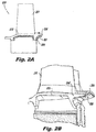
Fig. 2A is a cross-sectional elevation view of an embodiment of an assembly in accordance with this disclosure, showing a platform trailing edge seal disposed under a blade platform trailing edge; -
Fig. 2B is a side perspective view of the embodiment ofFig. 2A ; -
Fig. 2C is a front perspective view of the embodiment ofFig. 2A ; -
Fig. 3 is a cross-sectional elevation view of the assembly of claim 1, disposed in a turbomachine adjacent a vane; -
Fig. 4A is a cross-sectional elevation view of another embodiment of an assembly in accordance with this disclosure, showing a platform trailing edge seal disposed under a blade platform trailing edge and retained to the platform using an axial retaining feature and radial retaining feature; -
Fig. 4B is a perspective view of the embodiment ofFig. 4A , showing an axial retaining feature disposed thereon; -
Fig. 5A is a side perspective view of an embodiment of an assembly in accordance with this disclosure, showing a platform trailing edge seal disposed in a blade platform trailing edge; -
Fig. 5B is a side perspective view of the embodiment ofFig. 5A , showing the platform trailing edge seal removed from a slot in the blade platform trailing edge; and -
Fig. 5C is a top perspective view of the embodiment ofFig. 5A , showing adjacent blade platforms assembled together with the platform trailing edge seal therebetween. - Reference will now be made to the drawings wherein like reference numerals identify similar structural features or aspects of the subject disclosure. For purposes of explanation and illustration, and not limitation, an illustrative view of an embodiment of a
seal 200 andassembly 250 in accordance with the disclosure is shown inFigs. 2A . Other embodiments and/or aspects of this disclosure are shown inFigs. 1 and2A-5C . The systems and methods described herein can be used to improve the operating efficiency of a turbomachine. -
Fig. 1 schematically illustrates agas turbine engine 20. Thegas turbine engine 20 is disclosed herein as a two-spool turbofan that generally incorporates afan section 22, acompressor section 24, acombustor section 26 and a turbine section 28. Alternative engines might include an augmentor section (not shown) among other systems or features. Thefan section 22 drives air along a bypass flow path B in a bypass duct defined within anacelle 15, while thecompressor section 24 drives air along a core flow path C for compression and communication into thecombustor section 26 then expansion through the turbine section 28. Although depicted as a two-spool turbofan gas turbine engine in the disclosed non-limiting embodiment, it should be understood that the concepts described herein are not limited to use with two-spool turbofans as the teachings may be applied to other types of turbine engines including three-spool architectures. - The
exemplary engine 20 generally includes alow speed spool 30 and a high speed spool 32 mounted for rotation about an engine central longitudinal axis A relative to an enginestatic structure 36 viaseveral bearing systems 38. It should be understood that various bearingsystems 38 at various locations may alternatively or additionally be provided and the location of bearingsystems 38 may be varied as appropriate to the application. - The
low speed spool 30 generally includes an inner shaft 40 that interconnects afan 42, a first (or low) pressure compressor 44 and a first (or low) pressure turbine 46. The inner shaft 40 is connected to thefan 42 through a speed change mechanism, which in exemplarygas turbine engine 20 is illustrated as a gear system 48 to drive thefan 42 at a lower speed than thelow speed spool 30. The high speed spool 32 includes anouter shaft 50 that interconnects a second (or high)pressure compressor 52 and a second (or high) pressure turbine 54. A combustor 56 is arranged inexemplary gas turbine 20 between thehigh pressure compressor 52 and the high pressure turbine 54. A mid-turbine frame 57 of the enginestatic structure 36 is arranged generally between the high pressure turbine 54 and the low pressure turbine 46. The mid-turbine frame 57 furthersupports bearing systems 38 in the turbine section 28. The inner shaft 40 and theouter shaft 50 are concentric and rotate via bearingsystems 38 about the engine central longitudinal axis A which is collinear with their longitudinal axes. - The core airflow is compressed by the low pressure compressor 44 then the
high pressure compressor 52, mixed and burned with fuel in the combustor 56, then expanded over the high pressure turbine 54 and low pressure turbine 46. The mid-turbine frame 57 includesairfoils 59 which are in the core airflow path C. The turbines 46, 54 rotationally drive the respectivelow speed spool 30 and high speed spool 32 in response to the expansion. It will be appreciated that each of the positions of thefan section 22,compressor section 24,combustor section 26, turbine section 28, and fan gear system 48 may be varied. For example, gear system 48 may be located aft ofcombustor section 26 or even aft of turbine section 28, andfan section 22 may be positioned forward or aft of the location of gear system 48. - The
engine 20 in one example is a high-bypass geared aircraft engine. In a further example, theengine 20 bypass ratio is greater than about six (6), with an example embodiment being greater than about ten (10), the geared architecture is an epicyclic gear train, such as a planetary gear system or other gear system, with a gear reduction ratio of greater than about 2.3 and the low pressure turbine 46 has a pressure ratio that is greater than about five. In one disclosed embodiment, theengine 20 bypass ratio is greater than about ten (10:1), the fan diameter is significantly larger than that of the low pressure compressor 44, and the low pressure turbine 46 has a pressure ratio that is greater than about five (5:1). Low pressure turbine 46 pressure ratio is pressure measured prior to inlet of low pressure turbine 46 as related to the pressure at the outlet of the low pressure turbine 46 prior to an exhaust nozzle. The geared architecture may be an epicycle gear train, such as a planetary gear system or other gear system, with a gear reduction ratio of greater than about 2.3:1. It should be understood, however, that the above parameters are only exemplary of one embodiment of a geared architecture engine and that the present invention is applicable to other gas turbine engines including direct drive turbofans. - A significant amount of thrust is provided by the bypass flow B due to the high bypass ratio. The
fan section 22 of theengine 20 is designed for a particular flight condition -- typically cruise at about 0.8 Mach and about 35,000 feet. The flight condition of 0.8 Mach and 35,000 ft (10,668 meters), with the engine at its best fuel consumption - also known as "bucket cruise Thrust Specific Fuel Consumption ('TSFC')" - is the industry standard parameter of lbm of fuel being burned divided by lbf of thrust the engine produces at that minimum point. "Low fan pressure ratio" is the pressure ratio across the fan blade alone, without a Fan Exit Guide Vane 79("FEGV") system. The low fan pressure ratio as disclosed herein according to one non-limiting embodiment is less than about 1.45. "Low corrected fan tip speed" is the actual fan tip speed in ft/sec divided by an industry standard temperature correction of [(Tram °R) / (518.7 °R)]^0.5. The "Low corrected fan tip speed" as disclosed herein according to one non-limiting embodiment is less than about 1150 ft / second (350.5 meters/second). - Referring to
Figs. 2A-3 , a platform trailingedge seal 200 for aturbomachine blade assembly 250 includes abody 201 configured to extend into an aft portion of amateface gap 203 defined between a circumferentially adjacent pair ofturbomachine blade platforms 253 to minimize flow from entering a blade-vane cavity 301 (e.g., defined between theplatform trailing edge 255 andvane platform 303 as shown inFig. 3 ) through the aft portion of themateface gap 203. Theturbomachine blade assembly 250 can include ablade 251 having ablade platform 253 which defines a platform trailingedge portion 255. - The
body 201 of theseal 200 can include at least one of aluminum, titanium, nickel, and/or an alloy thereof. However, it is contemplated that theseal 200 can be made with any other suitable material. - As shown, the
body 201 can be shaped to match a shape of aplatform trailing edge 255. In certain embodiments, thebody 201 can be annular (e.g., full hoop). It is contemplated, however, that thebody 201 can define a segment of a seal structure (e.g., the seal structure being an annular structure) such that a plurality of theseals 200 can be disposed together to form an entire seal structure. - In certain embodiments, the platform trailing
edge seal 200 can be formed integrally with theplatform trailing edge 255. In such a case, eachseal 200 forms a segment of a seal structure (e.g., and annular structure) such that when a plurality ofblade assemblies 250 are placed adjacent to each other eachseal 200 reaches across theaft mateface gap 203 and partially into theadjacent blade platform 253 of theadjacent blade assembly 250. - In other embodiments, the platform trailing
edge seal 200 can be attached to theplatform trailing edge 255 as a separate piece in any suitable manner. For example, theblade platform 253 can include one or more protrusions for securing the platform trailingedge seal 200 to theblade platform 253. In certain embodiments (e.g., full hoop embodiments), the platform trailingedge seal 200 can be friction fit, thermally fit, and/or expansion fit to theblade platform 253. As shown inFigs. 4A and 4B , in certain embodiments, theassembly 250 can include one or more retaining features 401 (e.g., a clip) attached to theblade platform 253 at theplatform trailing edge 255 that are configured to retain the platform trailingedge seal 200 to theblade platform 253. - Referring to
Fig. 5A-5C , another embodiment of aseal 500 is shown disposed therein. As shownseal 500 can be configured as a feather seal to be disposed in aslot 501 that is defined at least partially in theplatform trailing edge 255 ofplatform 253. Theslot 501 can be of any suitable length (e.g., at least half as long as the platform trailing edge 253) and can be of any suitable depth. In such embodiments, theseal 500 can be a piece of sheet metal that is dimensioned to span the gap between circumferentiallyadjacent platforms 253 and/or to seat within correspondingslots 501 in the adjacent platforms. - As described herein, the
seal platform trailing edge 255 can prevent hot gas from being ingested into themateface gap 203 between theblade platforms 253. Theseal mateface gap 203 from the relatively low gaspath pressure just below themateface gap 203 in the blade-vane cavity 301 which decreases component temperatures and increases lifespan of the components. Additionally, some of the cooling flow that would traditionally be used to protect and cool this region would not be necessary, thus improving thrust specific fuel consumption. - In certain embodiments, the
seal seal above seal seal - The methods and systems of the present disclosure, as described above and shown in the drawings, provide for blade assemblies and seals with superior properties including improved thermal management. While the apparatus and methods of the subject disclosure have been shown and described with reference to embodiments, those skilled in the art will readily appreciate that changes and/or modifications may be made thereto without departing from the spirit and scope of the subject disclosure.
- The following clauses set out features of the invention which may or may not presently be claimed in this application but which may form the basis for future amendment or a divisional application.
- 1. A platform trailing edge seal for a turbomachine airfoil assembly, comprising:
- a body configured to extend into an aft portion of a mateface gap defined between a circumferentially adjacent pair of turbomachine airfoil platforms to minimize flow from entering a blade-vane cavity through the aft portion of the mateface gap.
- 2. The seal of clause 1, wherein the body includes at least one of aluminum, titanium, or nickel.
- 3. The seal of clause 1, wherein the body is shaped to match a platform trailing edge shape.
- 4. The seal of clause 1, wherein the body is annular.
- 5. The seal of clause 1, wherein the body defines a segment of an annular structure.
- 6. A turbomachine blade assembly, comprising:
- a blade having a blade platform which defines a platform trailing edge portion;
- and a platform trailing edge seal extending from the trailing edge portion, comprising:
- a body configured to extend into an aft portion of a mateface gap defined between the blade platform and an adjacent blade platform to minimize flow from entering a blade-vane cavity through the aft portion of the mateface gap.
- 7. The assembly of clause 6, wherein the platform trailing edge seal is formed integrally with the platform trailing edge.
- 8. The assembly of clause 6, wherein the platform trailing edge seal attached to the platform trailing edge.
- 9. The assembly of clause 6, wherein the body includes at least one of aluminum, titanium, or nickel.
- 10. The assembly of clause 6, wherein the body is shaped to match the platform trailing edge shape.
- 11. The assembly of clause 6, wherein the body is annular.
- 12. The assembly of clause 6, wherein the body defines a segment of an annular structure.
- 13. The assembly of clause 6, wherein the blade is located in one of a low pressure compressor, a high pressure compressor, a low pressure turbine, or a high pressure turbine.
- 14. The assembly of clause 6, wherein the platform trailing edge seal is friction fit, thermally fit, or expansion fit to the blade platform.
- 15. The assembly of clause 6, further including one or more retaining features attached to the blade platform and configured to retain the platform trailing edge seal to the blade platform.
- 16. A turbomachine, comprising:
- a turbomachine blade assembly, including:
- a blade having a blade platform which defines a platform trailing edge portion; and
- a platform trailing edge seal extending from the trailing edge portion,
- comprising: a body configured to extend into an aft portion of a mateface gap defined between the blade platform and an adjacent blade platform to minimize flow from entering a blade-vane cavity through the aft portion of the mateface gap.
- a turbomachine blade assembly, including:
- 17. The turbomachine of clause 16, wherein the platform trailing edge seal is formed integrally with the platform trailing edge.
- 18. The turbomachine of clause 16, wherein the platform trailing edge seal attached to the platform trailing edge.
- 19. The turbomachine of clause 16, wherein the body includes at least one of aluminum, titanium, or nickel.
- 20. The turbomachine of clause 16, wherein the body is shaped to match the platform trailing edge shape.
Claims (13)
- A platform trailing edge seal for a turbomachine airfoil assembly, comprising:a body configured to extend into an aft portion of a mateface gap defined between a circumferentially adjacent pair of turbomachine airfoil platforms to minimize flow from entering a blade-vane cavity through the aft portion of the mateface gap.
- The seal of claim 1, wherein the body includes at least one of aluminum, titanium, or nickel.
- The seal of any preceding claim, wherein the body is shaped to match a platform trailing edge shape.
- The seal of any preceding claim, wherein the body is annular.
- The seal of any of claims 1 to 3, wherein the body defines a segment of an annular structure.
- A turbomachine blade assembly, comprising:a blade having a blade platform which defines a platform trailing edge portion; and the platform trailing edge seal of any preceding claim extending from the trailing edge portion.
- The assembly of claim 6, wherein the platform trailing edge seal is formed integrally with the platform trailing edge.
- The assembly of claim 6 or 7, wherein the platform trailing edge seal attached to the platform trailing edge.
- The assembly of claim 6, 7 or 8, wherein the body is shaped to match the platform trailing edge shape.
- The assembly of any of claims 6 to 9, wherein the blade is located in one of a low pressure compressor, a high pressure compressor, a low pressure turbine, or a high pressure turbine.
- The assembly of any of claims 6 to 10, wherein the platform trailing edge seal is friction fit, thermally fit, or expansion fit to the blade platform.
- The assembly of any of claims 6 to 11, further including one or more retaining features attached to the blade platform and configured to retain the platform trailing edge seal to the blade platform.
- A turbomachine, comprising:the turbomachine blade assembly of any of claims 6 to 12.
Applications Claiming Priority (1)
| Application Number | Priority Date | Filing Date | Title |
|---|---|---|---|
| US14/726,722 US10196915B2 (en) | 2015-06-01 | 2015-06-01 | Trailing edge platform seals |
Publications (2)
| Publication Number | Publication Date |
|---|---|
| EP3101236A1 true EP3101236A1 (en) | 2016-12-07 |
| EP3101236B1 EP3101236B1 (en) | 2020-01-15 |
Family
ID=56081429
Family Applications (1)
| Application Number | Title | Priority Date | Filing Date |
|---|---|---|---|
| EP16171833.3A Active EP3101236B1 (en) | 2015-06-01 | 2016-05-27 | Trailing edge platform seals |
Country Status (2)
| Country | Link |
|---|---|
| US (1) | US10196915B2 (en) |
| EP (1) | EP3101236B1 (en) |
Cited By (1)
| Publication number | Priority date | Publication date | Assignee | Title |
|---|---|---|---|---|
| FR3107301A1 (en) * | 2020-02-19 | 2021-08-20 | Safran Aircraft Engines | blade for a movable bladed wheel of an aircraft turbomachine comprising a sealing spoiler with an optimized scalable section |
Families Citing this family (1)
| Publication number | Priority date | Publication date | Assignee | Title |
|---|---|---|---|---|
| US10753212B2 (en) * | 2017-08-23 | 2020-08-25 | Doosan Heavy Industries & Construction Co., Ltd | Turbine blade, turbine, and gas turbine having the same |
Citations (4)
| Publication number | Priority date | Publication date | Assignee | Title |
|---|---|---|---|---|
| EP0851097A2 (en) * | 1996-12-24 | 1998-07-01 | United Technologies Corporation | Turbine blade damper and seal |
| EP1380726A2 (en) * | 2002-07-10 | 2004-01-14 | Mitsubishi Heavy Industries, Ltd. | Stationary blade in gas turbine and gas turbine comprising the same |
| EP2093381A1 (en) * | 2008-02-25 | 2009-08-26 | Siemens Aktiengesellschaft | Turbine blade or vane with cooled platform |
| EP2679770A1 (en) * | 2012-06-26 | 2014-01-01 | Siemens Aktiengesellschaft | Platform seal strip for a gas turbine |
Family Cites Families (10)
| Publication number | Priority date | Publication date | Assignee | Title |
|---|---|---|---|---|
| US4580946A (en) * | 1984-11-26 | 1986-04-08 | General Electric Company | Fan blade platform seal |
| US4872810A (en) * | 1988-12-14 | 1989-10-10 | United Technologies Corporation | Turbine rotor retention system |
| US5513955A (en) * | 1994-12-14 | 1996-05-07 | United Technologies Corporation | Turbine engine rotor blade platform seal |
| US5820338A (en) | 1997-04-24 | 1998-10-13 | United Technologies Corporation | Fan blade interplatform seal |
| US6171058B1 (en) * | 1999-04-01 | 2001-01-09 | General Electric Company | Self retaining blade damper |
| DE50211431D1 (en) * | 2001-09-25 | 2008-02-07 | Alstom Technology Ltd | SEALING ARRANGEMENT FOR THE DENSITY PALL REDUCTION WITHIN A FLOW ROTATION MACHINE |
| US7762780B2 (en) * | 2007-01-25 | 2010-07-27 | Siemens Energy, Inc. | Blade assembly in a combustion turbo-machine providing reduced concentration of mechanical stress and a seal between adjacent assemblies |
| US8011892B2 (en) * | 2007-06-28 | 2011-09-06 | United Technologies Corporation | Turbine blade nested seal and damper assembly |
| US8820754B2 (en) * | 2010-06-11 | 2014-09-02 | Siemens Energy, Inc. | Turbine blade seal assembly |
| EP3044420A2 (en) * | 2013-09-11 | 2016-07-20 | General Electric Company | Ply architecture for integral platform and damper retaining features in cmc turbine blades |
-
2015
- 2015-06-01 US US14/726,722 patent/US10196915B2/en active Active
-
2016
- 2016-05-27 EP EP16171833.3A patent/EP3101236B1/en active Active
Patent Citations (4)
| Publication number | Priority date | Publication date | Assignee | Title |
|---|---|---|---|---|
| EP0851097A2 (en) * | 1996-12-24 | 1998-07-01 | United Technologies Corporation | Turbine blade damper and seal |
| EP1380726A2 (en) * | 2002-07-10 | 2004-01-14 | Mitsubishi Heavy Industries, Ltd. | Stationary blade in gas turbine and gas turbine comprising the same |
| EP2093381A1 (en) * | 2008-02-25 | 2009-08-26 | Siemens Aktiengesellschaft | Turbine blade or vane with cooled platform |
| EP2679770A1 (en) * | 2012-06-26 | 2014-01-01 | Siemens Aktiengesellschaft | Platform seal strip for a gas turbine |
Cited By (3)
| Publication number | Priority date | Publication date | Assignee | Title |
|---|---|---|---|---|
| FR3107301A1 (en) * | 2020-02-19 | 2021-08-20 | Safran Aircraft Engines | blade for a movable bladed wheel of an aircraft turbomachine comprising a sealing spoiler with an optimized scalable section |
| WO2021165600A1 (en) * | 2020-02-19 | 2021-08-26 | Safran Aircraft Engines | Blade for a rotating bladed disk for an aircrft turbine engine comprising a sealing lip having an optimized non-constant cross section |
| US11867065B2 (en) | 2020-02-19 | 2024-01-09 | Safran Aircraft Engines | Blade for a rotating bladed disk for an aircraft turbine engine comprising a sealing lip having an optimized non-constant cross section |
Also Published As
| Publication number | Publication date |
|---|---|
| US10196915B2 (en) | 2019-02-05 |
| US20160348525A1 (en) | 2016-12-01 |
| EP3101236B1 (en) | 2020-01-15 |
Similar Documents
| Publication | Publication Date | Title |
|---|---|---|
| EP3009599A1 (en) | Gas turbine engine component with film cooling hole feature | |
| US10041358B2 (en) | Gas turbine engine blade squealer pockets | |
| US10774655B2 (en) | Gas turbine engine component with flow separating rib | |
| EP3064711A1 (en) | Component, corresponding gas turbine engine and method | |
| EP3056680B1 (en) | Leakage air systems for turbomachines | |
| US20160169004A1 (en) | Cooling passages for gas turbine engine component | |
| EP3091184A1 (en) | Turbine airfoil leading edge cooling | |
| EP2952683A1 (en) | Gas turbine engine airfoil with large thickness properties | |
| EP3061910A1 (en) | Gas turbine engine airfoil and corresponding method of forming | |
| US20160208620A1 (en) | Gas turbine engine airfoil turbulator for airfoil creep resistance | |
| US10443421B2 (en) | Turbomachine blade assemblies | |
| US10746033B2 (en) | Gas turbine engine component | |
| US10655473B2 (en) | Gas turbine engine turbine blade leading edge tip trench cooling | |
| EP3051066A1 (en) | Staggerd casting core extensions | |
| EP3054093B1 (en) | Arrangement of trip strips | |
| EP3101236B1 (en) | Trailing edge platform seals | |
| EP2947268B1 (en) | Rotor heat shield for a lug of a rotor of a gas turbine engine | |
| EP2927429A1 (en) | Gas turbine engine component with flow separating rib | |
| EP3467260A1 (en) | Gas turbine engine airfoil with bowed tip | |
| EP2905427A1 (en) | Gas turbine engine sealing arrangement | |
| EP3045666B1 (en) | Airfoil platform with cooling feed orifices | |
| EP3401509B1 (en) | Blade outer air seal | |
| US20160032751A1 (en) | Reversible blade rotor seal | |
| EP2947272A1 (en) | Gas turbine engine stator vane baffle arrangement | |
| US20160326909A1 (en) | Gas turbine engine component with separation rib for cooling passages |
Legal Events
| Date | Code | Title | Description |
|---|---|---|---|
| PUAI | Public reference made under article 153(3) epc to a published international application that has entered the european phase |
Free format text: ORIGINAL CODE: 0009012 |
|
| STAA | Information on the status of an ep patent application or granted ep patent |
Free format text: STATUS: THE APPLICATION HAS BEEN PUBLISHED |
|
| AK | Designated contracting states |
Kind code of ref document: A1 Designated state(s): AL AT BE BG CH CY CZ DE DK EE ES FI FR GB GR HR HU IE IS IT LI LT LU LV MC MK MT NL NO PL PT RO RS SE SI SK SM TR |
|
| AX | Request for extension of the european patent |
Extension state: BA ME |
|
| STAA | Information on the status of an ep patent application or granted ep patent |
Free format text: STATUS: REQUEST FOR EXAMINATION WAS MADE |
|
| 17P | Request for examination filed |
Effective date: 20170607 |
|
| RBV | Designated contracting states (corrected) |
Designated state(s): AL AT BE BG CH CY CZ DE DK EE ES FI FR GB GR HR HU IE IS IT LI LT LU LV MC MK MT NL NO PL PT RO RS SE SI SK SM TR |
|
| STAA | Information on the status of an ep patent application or granted ep patent |
Free format text: STATUS: EXAMINATION IS IN PROGRESS |
|
| 17Q | First examination report despatched |
Effective date: 20180914 |
|
| GRAP | Despatch of communication of intention to grant a patent |
Free format text: ORIGINAL CODE: EPIDOSNIGR1 |
|
| STAA | Information on the status of an ep patent application or granted ep patent |
Free format text: STATUS: GRANT OF PATENT IS INTENDED |
|
| INTG | Intention to grant announced |
Effective date: 20190806 |
|
| GRAS | Grant fee paid |
Free format text: ORIGINAL CODE: EPIDOSNIGR3 |
|
| GRAA | (expected) grant |
Free format text: ORIGINAL CODE: 0009210 |
|
| STAA | Information on the status of an ep patent application or granted ep patent |
Free format text: STATUS: THE PATENT HAS BEEN GRANTED |
|
| AK | Designated contracting states |
Kind code of ref document: B1 Designated state(s): AL AT BE BG CH CY CZ DE DK EE ES FI FR GB GR HR HU IE IS IT LI LT LU LV MC MK MT NL NO PL PT RO RS SE SI SK SM TR |
|
| REG | Reference to a national code |
Ref country code: CH Ref legal event code: EP Ref country code: GB Ref legal event code: FG4D |
|
| REG | Reference to a national code |
Ref country code: IE Ref legal event code: FG4D |
|
| REG | Reference to a national code |
Ref country code: DE Ref legal event code: R096 Ref document number: 602016028171 Country of ref document: DE |
|
| REG | Reference to a national code |
Ref country code: AT Ref legal event code: REF Ref document number: 1225318 Country of ref document: AT Kind code of ref document: T Effective date: 20200215 |
|
| REG | Reference to a national code |
Ref country code: NL Ref legal event code: MP Effective date: 20200115 |
|
| REG | Reference to a national code |
Ref country code: LT Ref legal event code: MG4D |
|
| PG25 | Lapsed in a contracting state [announced via postgrant information from national office to epo] |
Ref country code: RS Free format text: LAPSE BECAUSE OF FAILURE TO SUBMIT A TRANSLATION OF THE DESCRIPTION OR TO PAY THE FEE WITHIN THE PRESCRIBED TIME-LIMIT Effective date: 20200115 Ref country code: NO Free format text: LAPSE BECAUSE OF FAILURE TO SUBMIT A TRANSLATION OF THE DESCRIPTION OR TO PAY THE FEE WITHIN THE PRESCRIBED TIME-LIMIT Effective date: 20200415 Ref country code: PT Free format text: LAPSE BECAUSE OF FAILURE TO SUBMIT A TRANSLATION OF THE DESCRIPTION OR TO PAY THE FEE WITHIN THE PRESCRIBED TIME-LIMIT Effective date: 20200607 Ref country code: FI Free format text: LAPSE BECAUSE OF FAILURE TO SUBMIT A TRANSLATION OF THE DESCRIPTION OR TO PAY THE FEE WITHIN THE PRESCRIBED TIME-LIMIT Effective date: 20200115 Ref country code: NL Free format text: LAPSE BECAUSE OF FAILURE TO SUBMIT A TRANSLATION OF THE DESCRIPTION OR TO PAY THE FEE WITHIN THE PRESCRIBED TIME-LIMIT Effective date: 20200115 |
|
| PG25 | Lapsed in a contracting state [announced via postgrant information from national office to epo] |
Ref country code: IS Free format text: LAPSE BECAUSE OF FAILURE TO SUBMIT A TRANSLATION OF THE DESCRIPTION OR TO PAY THE FEE WITHIN THE PRESCRIBED TIME-LIMIT Effective date: 20200515 Ref country code: BG Free format text: LAPSE BECAUSE OF FAILURE TO SUBMIT A TRANSLATION OF THE DESCRIPTION OR TO PAY THE FEE WITHIN THE PRESCRIBED TIME-LIMIT Effective date: 20200415 Ref country code: SE Free format text: LAPSE BECAUSE OF FAILURE TO SUBMIT A TRANSLATION OF THE DESCRIPTION OR TO PAY THE FEE WITHIN THE PRESCRIBED TIME-LIMIT Effective date: 20200115 Ref country code: LV Free format text: LAPSE BECAUSE OF FAILURE TO SUBMIT A TRANSLATION OF THE DESCRIPTION OR TO PAY THE FEE WITHIN THE PRESCRIBED TIME-LIMIT Effective date: 20200115 Ref country code: GR Free format text: LAPSE BECAUSE OF FAILURE TO SUBMIT A TRANSLATION OF THE DESCRIPTION OR TO PAY THE FEE WITHIN THE PRESCRIBED TIME-LIMIT Effective date: 20200416 Ref country code: HR Free format text: LAPSE BECAUSE OF FAILURE TO SUBMIT A TRANSLATION OF THE DESCRIPTION OR TO PAY THE FEE WITHIN THE PRESCRIBED TIME-LIMIT Effective date: 20200115 |
|
| REG | Reference to a national code |
Ref country code: DE Ref legal event code: R097 Ref document number: 602016028171 Country of ref document: DE |
|
| PG25 | Lapsed in a contracting state [announced via postgrant information from national office to epo] |
Ref country code: DK Free format text: LAPSE BECAUSE OF FAILURE TO SUBMIT A TRANSLATION OF THE DESCRIPTION OR TO PAY THE FEE WITHIN THE PRESCRIBED TIME-LIMIT Effective date: 20200115 Ref country code: SM Free format text: LAPSE BECAUSE OF FAILURE TO SUBMIT A TRANSLATION OF THE DESCRIPTION OR TO PAY THE FEE WITHIN THE PRESCRIBED TIME-LIMIT Effective date: 20200115 Ref country code: EE Free format text: LAPSE BECAUSE OF FAILURE TO SUBMIT A TRANSLATION OF THE DESCRIPTION OR TO PAY THE FEE WITHIN THE PRESCRIBED TIME-LIMIT Effective date: 20200115 Ref country code: SK Free format text: LAPSE BECAUSE OF FAILURE TO SUBMIT A TRANSLATION OF THE DESCRIPTION OR TO PAY THE FEE WITHIN THE PRESCRIBED TIME-LIMIT Effective date: 20200115 Ref country code: CZ Free format text: LAPSE BECAUSE OF FAILURE TO SUBMIT A TRANSLATION OF THE DESCRIPTION OR TO PAY THE FEE WITHIN THE PRESCRIBED TIME-LIMIT Effective date: 20200115 Ref country code: ES Free format text: LAPSE BECAUSE OF FAILURE TO SUBMIT A TRANSLATION OF THE DESCRIPTION OR TO PAY THE FEE WITHIN THE PRESCRIBED TIME-LIMIT Effective date: 20200115 Ref country code: RO Free format text: LAPSE BECAUSE OF FAILURE TO SUBMIT A TRANSLATION OF THE DESCRIPTION OR TO PAY THE FEE WITHIN THE PRESCRIBED TIME-LIMIT Effective date: 20200115 Ref country code: LT Free format text: LAPSE BECAUSE OF FAILURE TO SUBMIT A TRANSLATION OF THE DESCRIPTION OR TO PAY THE FEE WITHIN THE PRESCRIBED TIME-LIMIT Effective date: 20200115 |
|
| REG | Reference to a national code |
Ref country code: AT Ref legal event code: MK05 Ref document number: 1225318 Country of ref document: AT Kind code of ref document: T Effective date: 20200115 |
|
| PLBE | No opposition filed within time limit |
Free format text: ORIGINAL CODE: 0009261 |
|
| STAA | Information on the status of an ep patent application or granted ep patent |
Free format text: STATUS: NO OPPOSITION FILED WITHIN TIME LIMIT |
|
| 26N | No opposition filed |
Effective date: 20201016 |
|
| PG25 | Lapsed in a contracting state [announced via postgrant information from national office to epo] |
Ref country code: IT Free format text: LAPSE BECAUSE OF FAILURE TO SUBMIT A TRANSLATION OF THE DESCRIPTION OR TO PAY THE FEE WITHIN THE PRESCRIBED TIME-LIMIT Effective date: 20200115 Ref country code: MC Free format text: LAPSE BECAUSE OF FAILURE TO SUBMIT A TRANSLATION OF THE DESCRIPTION OR TO PAY THE FEE WITHIN THE PRESCRIBED TIME-LIMIT Effective date: 20200115 Ref country code: AT Free format text: LAPSE BECAUSE OF FAILURE TO SUBMIT A TRANSLATION OF THE DESCRIPTION OR TO PAY THE FEE WITHIN THE PRESCRIBED TIME-LIMIT Effective date: 20200115 Ref country code: CH Free format text: LAPSE BECAUSE OF NON-PAYMENT OF DUE FEES Effective date: 20200531 Ref country code: LI Free format text: LAPSE BECAUSE OF NON-PAYMENT OF DUE FEES Effective date: 20200531 |
|
| PG25 | Lapsed in a contracting state [announced via postgrant information from national office to epo] |
Ref country code: SI Free format text: LAPSE BECAUSE OF FAILURE TO SUBMIT A TRANSLATION OF THE DESCRIPTION OR TO PAY THE FEE WITHIN THE PRESCRIBED TIME-LIMIT Effective date: 20200115 Ref country code: PL Free format text: LAPSE BECAUSE OF FAILURE TO SUBMIT A TRANSLATION OF THE DESCRIPTION OR TO PAY THE FEE WITHIN THE PRESCRIBED TIME-LIMIT Effective date: 20200115 |
|
| REG | Reference to a national code |
Ref country code: BE Ref legal event code: MM Effective date: 20200531 |
|
| PG25 | Lapsed in a contracting state [announced via postgrant information from national office to epo] |
Ref country code: LU Free format text: LAPSE BECAUSE OF NON-PAYMENT OF DUE FEES Effective date: 20200527 |
|
| PG25 | Lapsed in a contracting state [announced via postgrant information from national office to epo] |
Ref country code: IE Free format text: LAPSE BECAUSE OF NON-PAYMENT OF DUE FEES Effective date: 20200527 |
|
| PG25 | Lapsed in a contracting state [announced via postgrant information from national office to epo] |
Ref country code: BE Free format text: LAPSE BECAUSE OF NON-PAYMENT OF DUE FEES Effective date: 20200531 |
|
| PG25 | Lapsed in a contracting state [announced via postgrant information from national office to epo] |
Ref country code: TR Free format text: LAPSE BECAUSE OF FAILURE TO SUBMIT A TRANSLATION OF THE DESCRIPTION OR TO PAY THE FEE WITHIN THE PRESCRIBED TIME-LIMIT Effective date: 20200115 Ref country code: MT Free format text: LAPSE BECAUSE OF FAILURE TO SUBMIT A TRANSLATION OF THE DESCRIPTION OR TO PAY THE FEE WITHIN THE PRESCRIBED TIME-LIMIT Effective date: 20200115 Ref country code: CY Free format text: LAPSE BECAUSE OF FAILURE TO SUBMIT A TRANSLATION OF THE DESCRIPTION OR TO PAY THE FEE WITHIN THE PRESCRIBED TIME-LIMIT Effective date: 20200115 |
|
| PG25 | Lapsed in a contracting state [announced via postgrant information from national office to epo] |
Ref country code: MK Free format text: LAPSE BECAUSE OF FAILURE TO SUBMIT A TRANSLATION OF THE DESCRIPTION OR TO PAY THE FEE WITHIN THE PRESCRIBED TIME-LIMIT Effective date: 20200115 Ref country code: AL Free format text: LAPSE BECAUSE OF FAILURE TO SUBMIT A TRANSLATION OF THE DESCRIPTION OR TO PAY THE FEE WITHIN THE PRESCRIBED TIME-LIMIT Effective date: 20200115 |
|
| REG | Reference to a national code |
Ref country code: DE Ref legal event code: R081 Ref document number: 602016028171 Country of ref document: DE Owner name: RAYTHEON TECHNOLOGIES CORPORATION (N.D.GES.D.S, US Free format text: FORMER OWNER: UNITED TECHNOLOGIES CORPORATION, FARMINGTON, CONN., US |
|
| P01 | Opt-out of the competence of the unified patent court (upc) registered |
Effective date: 20230520 |
|
| PGFP | Annual fee paid to national office [announced via postgrant information from national office to epo] |
Ref country code: FR Payment date: 20230420 Year of fee payment: 8 Ref country code: DE Payment date: 20230419 Year of fee payment: 8 |
|
| PGFP | Annual fee paid to national office [announced via postgrant information from national office to epo] |
Ref country code: GB Payment date: 20230420 Year of fee payment: 8 |