EP3100960A2 - Abgabesystem für filmumhüllung - Google Patents
Abgabesystem für filmumhüllung Download PDFInfo
- Publication number
- EP3100960A2 EP3100960A2 EP16172273.1A EP16172273A EP3100960A2 EP 3100960 A2 EP3100960 A2 EP 3100960A2 EP 16172273 A EP16172273 A EP 16172273A EP 3100960 A2 EP3100960 A2 EP 3100960A2
- Authority
- EP
- European Patent Office
- Prior art keywords
- core
- film
- connector portion
- dispenser
- edge
- Prior art date
- Legal status (The legal status is an assumption and is not a legal conclusion. Google has not performed a legal analysis and makes no representation as to the accuracy of the status listed.)
- Granted
Links
Images
Classifications
-
- B—PERFORMING OPERATIONS; TRANSPORTING
- B65—CONVEYING; PACKING; STORING; HANDLING THIN OR FILAMENTARY MATERIAL
- B65B—MACHINES, APPARATUS OR DEVICES FOR, OR METHODS OF, PACKAGING ARTICLES OR MATERIALS; UNPACKING
- B65B67/00—Apparatus or devices facilitating manual packaging operations; Sack holders
- B65B67/08—Wrapping of articles
- B65B67/085—Wrapping of articles using hand-held dispensers for stretch films
-
- B—PERFORMING OPERATIONS; TRANSPORTING
- B65—CONVEYING; PACKING; STORING; HANDLING THIN OR FILAMENTARY MATERIAL
- B65H—HANDLING THIN OR FILAMENTARY MATERIAL, e.g. SHEETS, WEBS, CABLES
- B65H16/00—Unwinding, paying-out webs
- B65H16/02—Supporting web roll
- B65H16/06—Supporting web roll both-ends type
-
- B—PERFORMING OPERATIONS; TRANSPORTING
- B65—CONVEYING; PACKING; STORING; HANDLING THIN OR FILAMENTARY MATERIAL
- B65B—MACHINES, APPARATUS OR DEVICES FOR, OR METHODS OF, PACKAGING ARTICLES OR MATERIALS; UNPACKING
- B65B11/00—Wrapping, e.g. partially or wholly enclosing, articles or quantities of material, in strips, sheets or blanks, of flexible material
- B65B11/02—Wrapping articles or quantities of material, without changing their position during the wrapping operation, e.g. in moulds with hinged folders
-
- B—PERFORMING OPERATIONS; TRANSPORTING
- B65—CONVEYING; PACKING; STORING; HANDLING THIN OR FILAMENTARY MATERIAL
- B65B—MACHINES, APPARATUS OR DEVICES FOR, OR METHODS OF, PACKAGING ARTICLES OR MATERIALS; UNPACKING
- B65B59/00—Arrangements to enable machines to handle articles of different sizes, to produce packages of different sizes, to vary the contents of packages, to handle different types of packaging material, or to give access for cleaning or maintenance purposes
- B65B59/04—Machines constructed with readily-detachable units or assemblies, e.g. to facilitate maintenance
-
- B—PERFORMING OPERATIONS; TRANSPORTING
- B65—CONVEYING; PACKING; STORING; HANDLING THIN OR FILAMENTARY MATERIAL
- B65H—HANDLING THIN OR FILAMENTARY MATERIAL, e.g. SHEETS, WEBS, CABLES
- B65H19/00—Changing the web roll
- B65H19/10—Changing the web roll in unwinding mechanisms or in connection with unwinding operations
- B65H19/12—Lifting, transporting, or inserting the web roll; Removing empty core
-
- B—PERFORMING OPERATIONS; TRANSPORTING
- B65—CONVEYING; PACKING; STORING; HANDLING THIN OR FILAMENTARY MATERIAL
- B65H—HANDLING THIN OR FILAMENTARY MATERIAL, e.g. SHEETS, WEBS, CABLES
- B65H23/00—Registering, tensioning, smoothing or guiding webs
- B65H23/04—Registering, tensioning, smoothing or guiding webs longitudinally
- B65H23/06—Registering, tensioning, smoothing or guiding webs longitudinally by retarding devices, e.g. acting on web-roll spindle
- B65H23/063—Registering, tensioning, smoothing or guiding webs longitudinally by retarding devices, e.g. acting on web-roll spindle and controlling web tension
-
- B—PERFORMING OPERATIONS; TRANSPORTING
- B65—CONVEYING; PACKING; STORING; HANDLING THIN OR FILAMENTARY MATERIAL
- B65H—HANDLING THIN OR FILAMENTARY MATERIAL, e.g. SHEETS, WEBS, CABLES
- B65H2301/00—Handling processes for sheets or webs
- B65H2301/40—Type of handling process
- B65H2301/41—Winding, unwinding
- B65H2301/413—Supporting web roll
- B65H2301/4134—Both ends type arrangement
-
- B—PERFORMING OPERATIONS; TRANSPORTING
- B65—CONVEYING; PACKING; STORING; HANDLING THIN OR FILAMENTARY MATERIAL
- B65H—HANDLING THIN OR FILAMENTARY MATERIAL, e.g. SHEETS, WEBS, CABLES
- B65H2301/00—Handling processes for sheets or webs
- B65H2301/40—Type of handling process
- B65H2301/41—Winding, unwinding
- B65H2301/417—Handling or changing web rolls
- B65H2301/418—Changing web roll
Definitions
- This invention relates to a dispenser, in particular a dispenser for dispensing stretch film to be applied to a load filled pallet.
- stretch film which is a highly stretchable plastic film
- stretch wrap which is a highly stretchable plastic film
- the use of stretch film also offers more efficient handling and storage of unit loads, a degree of tamper resistance and can deter package pilferage.
- the film can also be considered to provide a degree of protection against dust, moisture and in some instances (depending on the material of the stretch wrap) sunlight.
- Stretch wrap dispensers are known whereby the dispenser comprises a shaft for receiving and supporting the core of a roll of stretch wrap.
- the dispenser is designed to be held at the top and the side of the dispenser to enable the wrap to be applied to the desired items.
- the dispenser may further comprise a brake system for providing resistance so as to create stretch of the film.
- Such dispensers are known to be cumbersome to use since the position of the hand grips are far from being ergonomically distributed. This results in a non-conventional hand position of the user causing them to bend over, which can lead to back or related injuries.
- the user may opt not to hold the dispenser via the hand grips, which may provide an uncomfortable user experience due to the user having to hold onto sharp metal edges or due to the dispenser slipping out of the user's hands.
- Currently available dispensers can also be considered bulky and when they are made from steel, which is the conventional material, the dispenser is heavy. In some instances it is difficult and time consuming to refresh the dispenser with a refill.
- a dispenser having a first and second connector spaced apart, whereby the roll of stretch wrap is provided between the first and second connector. Whilst there may no longer be the requirement of removing the core of the stretch wrap from a shaft, such systems have been found to be cumbersome when inserting a replacement stretch wrap, and therefore refilling such dispensers is still considered to be time consuming.
- the roll of film is a standard product and the dispenser may not be optimised thereby allowing for slippage of the roll of film with respect to the dispenser as the film is applied to a load to be wrapped.
- the present invention and its embodiments are intended to address at least some of the above described problems and desires.
- it enables the stretch wrap to be applied in an efficient and ergonomic manner, thereby encouraging a good working practice when applying the wrap to a pallet containing a load.
- This in addition to providing a secure non slip retention of the film, smooth consistent action of the film and optimised tension control of the film for the user is expected to reduce back and related injuries.
- the improved mechanism for inserting and removing a roll of film contributes to the efficiency of wrapping the pallet and its load, whilst utilising the dispenser. Therefore, the invention provides an improved user experience whereby the dispenser aids the stretch wrapping process.
- a: system for dispensing film wrap, the apparatus comprising:
- the core may be tubular.
- the dispenser may comprise a main body having a first and second end; the first connector portion being configured proximate to the first end of the main body; and the second connector portion being configured at the second end of the main body, the first and second connector portions being spaced apart from each other along a common axis, wherein the film wrap is arranged between the first connector portion and the second connector portion along the common axis.
- At least part of the profiled end of the wall of the core of the edge of the film wrap may define the female part of an interlockable arrangement and the interlocking member of the first and/or second connector portion may define the male part of an interlockable arrangement whereby the first part and the second part are couplable.
- At least part of the profiled edge of the wall of the core and/or the film wrap may be provided by a notch located at an end of the core and/or the edge of the film wrap wound around the core.
- the notch may be a cutaway portion provided in a wall of the core of the film wrap.
- the notch may extend from an edge of the core to a position spaced apart from the edge of the core such that the notch extends substantially parallel to the longitudinal axis of the core.
- first notch and a second notch positioned diametrically opposed to each other.
- the complimentary interlocking member on the first and/or second connector may be a protrusion receivable within the notch.
- the interlocking member comprises a first disc portion having a tubular hub extending outwardly at its centre.
- a first protrusion extends radially from the hub in a first direction and a second protrusion extends radially from the hub in a second direction opposing the first direction.
- the first and second projection may be diametrically opposed.
- the first and second protrusion may be an elongate protrusion defining a paddle type arrangement.
- the first or second connector portion may comprise a film wrap tension controller.
- a tension controller may terminate the upper end of the first or second connector portion.
- the tension controller may comprise an adjustable portion that may be rotatable and in mechanical communication with a moveable part configured intermediate to the actuator and an end of the roll of film so as to provide tension control of the film.
- the adjustable portion may be a rotatable knob and the moveable part is a bolt having a clamping mechanism.
- the clamping mechanism may comprise a nut having a first and second part configurable between a first configuration wherein the first and second part are arranged in contact with each other enabling movement of the nut along the thread of the bolt in a first direction and a second configuration wherein the first and second part of the nut are spaced apart so as to provide a freewheeling state which prohibits movement of the nut along the longitudinal axis of the bolt.
- the system may comprise a quick release mechanism for configuring the clamping mechanism between a freewheeling state and a moveable state.
- the system may comprise an actuator for actuating the moveable state of the clamping mechanism.
- the actuator may be configured to terminate the first end of the main body.
- the actuator may be a push button switch.
- the actuator may be in mechanical communication with the clamping mechanism.
- the system may comprise a biasing member in mechanical communication with the clamping mechanism and for enabling relative movement between the nut and the thread on actuation of the actuator.
- the biasing member may be configured to bias the nut such that it moves in the second direction opposing the first direction.
- the biasing member may be a spring.
- the system may comprise a braking mechanism located at the first connector portion and configured to prevent rotational movement of the core of the film when the brake is applied.
- the braking mechanism may comprise a rubberised material located at the base of the first connector portion.
- the first connector portion may be terminated by a first interlocking member and the second connector portion may be terminated by a second interlocking member.
- the first profiled edge may be identical to the second profiled edge.
- the first profiled edge of the first connector portion may be interlockable with a profiled edge at one end of the wall of the roll of film and the second profiled edge of the second connector portion may be interlockable with the profiled edge at the other end of the wall of the roll of film so as to prevent relative lateral movement between the dispenser and the roll of film.
- the main body may comprise a first and second curved portion with a straight portion positioned there-between.
- the system may further comprise a first handle located on at least one of the curved portions.
- the handle may be located on the curved portion located above the straight portion.
- the system may comprise a second handle positioned on the straight portion.
- the second handle may be positioned at the base of the straight portion.
- the first and/or second handle may be made from rubber enabling a user to grip the system securely.
- the dispenser may comprise a base foot connected to a base region of the first or second connector portion.
- At least part of the base foot may have a curved edge.
- the profiled end may be provided by a protrusion extending from a side edge of the core of the film wrap.
- the complimentary interlocking profile on the first and/or second connector may be a recess for receiving the protrusion.
- the control unit may comprise a bolt with a clamping mechanism.
- the clamping mechanism may comprise a nut having a first and second part configurable between a first configuration wherein the first and second part are arranged in contact with each other enabling movement of the nut along the thread of the bolt in a first direction and a second configuration wherein the first and second part of the nut are spaced apart so as to provide a freewheeling state which prohibits movement of the nut along the longitudinal axis of the bolt.
- the dispenser may further comprise a biasing member in mechanical communication with the clamping mechanism and for enabling relative movement between the nut and the bolt when the nut is in the first configuration.
- the second connector portion may be terminated by a second interlocking means configurable to, in use, cooperate with a corresponding profiled edge located at an end of a core of a roll of film wrap to be fixedly arranged between the first connector portion and the second connector portion along the common axis.
- a roll of film wrap for use in the above-mentioned system comprising:
- the profiled edge may be provided at each end of the core.
- the profiled edge may comprise a notch.
- the notch may comprise a cutaway portion located in the core or the edge of the film wrapped about the core.
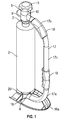
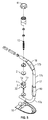
- a system for dispensing film wrap comprising a dispenser having a first connector portion 1 and second connector portion 2 spaced apart from the first connector portion 1.
- a roll of film wrap comprising a core 3 having film wrap wound thereon is configured to extend between the first connector 1 portion and the second connector portion 2 of the dispenser.
- At least one end wall of the core of the film wrap is profiled and interlockable with a complimentary interlocking means located at the remote end of the first connector portion 1 so as to prevent lateral movement of the film wrap and to prevent the core from slipping with respect to the dispenser.
- the first and second connector portions, 1 and 2 are rotatable to permit rotation of the film wrap.
- the dispenser is therefore not to be used with a standard roll of film supplied in the industry since this standard roll of film is prevented from being installed by the complimentary interlocking means provided on the first connector portion.
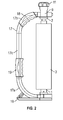
- the dispenser comprises a main body, at least part of which follows an arcuate path.
- the main body has a first end 4 and second end 5.
- the first connector portion 1 is configured proximate to the first end 4 of the main body.
- the first end 4 is positioned below the second end 5 in normal working use and when in the usual stored position. Therefore, the first connector portion 1 is located at the base of the dispenser.
- the second connector portion 2 is configured at the second end 5 of the main body, which is considered to be the top region.
- the first and second connector portions, 1 and 2 which effectively act as spigots, are spaced apart from each other along a common axis such that the remote ends of the connector portions are configured to face each other.
- the distance between the first and second connector portion may, for example, be between 350 mm to 650 mm, say between 400 and 500 mm in one specific exemplary embodiment, but the present invention is in no way intended to be limited in this regard.
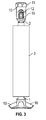
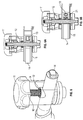
- At least part of the profiled end of the film wrap defines the female part (not shown) of an interlockable arrangement and the interlocking means of the first connector portion 1 defines the male part 7 of the interlockable arrangement whereby the female part (not shown) and the male part 7 are couplable.
- the profiled end comprises an interrupted circumferential edge, wherein the interrupted circumferential edge of the core defines a stepped profile. Therefore the profiled end is not merely linear as per standard rolls of film wrap that are supplied.
- the profiled edge of the film wrap core is provided by a notch or recess (as shown in Figure 2 ) located in the wall of the core and is located at an end of the core 3 and/or the edge of the film wrap supported by the core 3.
- the recess or notch (not shown) is, for example, a cutaway portion provided in a wall of the core 3 of the film wrap.
- the core 3 of the roll is open-ended, i.e. the core 3 is tubular in form.
- the notch is located in the wall of the tube and is separate and distinct from the opening of the tube.
- the first and second notch (as shown in Figure 2 in part) comprises a first cutaway portion of the wall and a second cutaway portion of the wall positioned diametrically opposed to the first cutaway portion.
- the cutaway portion or notch extends from the side edge of the core to a position spaced apart from the edge of the core such that the notch extends parallel with respect to the longitudinal axis of the core.
- the complimentary interlocking means on the first connector 1 is a protrusion 7 shaped to be receivable within the recess or notch(not shown).
- Figure 2 shows the first connector portion to be formed of a base plate having a raised hub portion that is insertable into the opening of the tube of the core and from which extend the first and second paddle like protrusions that extend from the cylindrical hub to the edge of the base plate.
- the base plate is a circular disc like structure. Therefore, a roll of film having a core with a flat edge is not capable of forming a seamless interface with the first connector since the paddle like protrusion of the first connector prevents contact of the edge of the core with the base plate of the first connector portion.
- the second connector portion 2 is terminated by a central cylinder portion which is receivable within the interior of the core so as to interlock the top edge of the second end of the core with the second connector portion so as to fixedly arrange a roll of film wrap between the first connector portion 1 and the second connector portion 2 along the common axis.
- the first interlocking means is the protrusion 7 which is configured to, in use, to be received by the notch (not shown) positioned at a co-operable end of the core of the roll of film wrap so as to effect an interlocked state between the co-operable end of the core 3 and the first connector portion 1.
- the first and second end of the protrusion 7 are receivable within a first and second diametrically opposed cutaway portion (not shown) located at the edge of the core of the roll of film wrap respectively. Therefore, to ensure the required interlocked state, the recess is shaped and configured to snugly receive the protrusion 7. It can be appreciated that a locked state is achieved by the end of the roll and the end of the connector portion rather than merely a friction fit. As a result the notched core interfaces seamlessly with the first connector portion of the dispenser.
- the first connector portion 1 is positioned proximate to the first end of the main body and is a substantially cylindrical portion having an aperture 1 a extending there-through. At least part of the main body is configured to pass through the aperture 1a of the first connector. This ensures that the main body is connected to the first connector and that the actuator 14, which is positioned on the first end of the main body is easily accessible for the user.
- the dispenser comprises a single control unit 9 providing quick release and tension control.
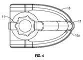
- a tension controller 10 terminates the upper end of the substantially cylindrical portion of the second connector portion 2.
- the tension controller 10 adjusts the speed and degree of rotation of the roll of film so as to apply the required level of tension to the film enabling the film to be stretched. For example to ensure the contents of the pallet are tightly wrapped, the tension is increased to minimise or even prevent rotation of the roll of film.
- the tension controller comprises a rotatable knob 11 which is in mechanical communication with a bolt 12 having a one way thread and clamping mechanism located on the bolt 12.
- a piece of rubberised material 22 is provided at the base of the first connector portion 1.
- the remote end of the bolt 12 provides a pressure on the top of the roll of film via the second or upper connector portion 2. This ultimately brings the end of the thread into contact with the top end of the roll of film. This pressure is transferred down to the first or base connector portion 1. This effectively squeezes the roll between the first and second connector portion.
- the rubberised composite material located at the base of the second connector portion 2 acts as a brake.
- the knob 11 and composite material arrangement can be operated between a first configuration, as shown in Figure 6a , allowing free rotation of the roll of film located on the dispenser and a second configuration, as shown in Figure 6b , whereby the roll of film is prevented from rotating.
- Different tension points are provided as the knob 11 is configured between the first and second configuration. Due to the squeezing effect, when one end of the roll of film is prevented from moving, so to is the other end of the roll of film.
- the bolt 12 is applied with a moveable carriage 21, for example a nut 21 that is rotatable about the thread so as to cause movement along the longitudinal axis of the bolt 12.
- the nut 21 also provides a clamping mechanism enabling a stop effect since it is split into two parts that, when the two parts are pulled apart, cause freewheeling of the nut on the thread of the bolt.
- the knob 11 causes helical movement of the carriage along the longitudinal axis of the bolt 12 in the first and second direction, depending on the direction of rotation of the knob 11. This helical movement only occurs when the first and second part of the nut 21 are brought together. Movement of the nut 21 along the longitudinal axis of the bolt 12 corresponds to different tension states of the roll.
- the clamping mechanism is spring loaded such that when the nut 21 is removed from the freewheeling state it is biased to return to its starting position whereby the tension applied to the roll is at a minimum.
- a biasing member 13 for example, a spring, is configured such that when the button 14 is depressed and the carriage is released from the stop position (caused by the freewheeling of the nut), and the biasing member 13 causes movement of the carriage in the second longitudinal direction to release the tension applied to the top of the roll and to enable the removal or insertion of the roll of film as desired i.e. to enable the profiled end 6 at the base of the roll to be removed from the interlocking means of the lower connector portion 1.
- This provides a rapid roll change system.
- An actuator is configured on the end of the first end of the main body for actuating the quick release state whereby the actuator is in the form of a press button 14.
- the press button 14 is the external face of a spring loaded split pin 15 which is in mechanical communication with a biasing member 13, for example, a spring, on its internal face 15a. Depression of the press button 14 forces the pin 15 to slide horizontally relative to the bolt 12, compressing the spring 13, and disconnecting the two parts of the nut 21, thereby opening the pin 14. This activates the quick release mechanism, enabling the bolt 12 to slide rapidly vertically relative to the female part, thereby relieving the tension on top of the roll or film and allowing for the removal of insertion of a roll or film.
- a quick release mechanism is provided with the depression of a single button 14 which enables the release of the roll of film or the core 3 of the roll once the film has been depleted. Similarly on loading the film, the complete spring loaded mechanism is depressed in a single action to enable the ends locate the film.
- the roll of film is located in the desired position the user can push down on the twist lock knob and the roll is secured into position. Therefore, the roll is installed by a simple push fit action which is extremely efficient to apply.
- the first connector portion 1 terminates a first end of the main body. This end can be considered to be the base 16 or lower end of the main body when in normal use or in a stored state.
- the main portion 17 comprises a first 17a and second 17b curved portion with a straight portion 17c positioned there-between.
- a first handle 18 is located on at least one of the curved portions, for example the curved portion 17b located above the straight portion.
- a second handle 19 is also positioned on the straight portion 17c, for example the second handle is located at the base of the straight portion 17c.
- the first 18 and/or second 19 handle is made from rubber to provide an improved grip of a user.
- the handle is also shaped to enable the moulding of the handle to a person's hand in an ergonomic manner.
- the dispenser comprises a base foot 16 connected at one end to the base region 20 of the second connector portion 2.
- the other end of the base foot 16 is connected to the lower curved region 17a of the main body, i.e. below the second handle.
- the base foot 16 acts as a stand when the dispenser is to be stored to one side or when the user has a break in applying the stretch wrap.
- At least part of the base foot 16 has a curved edge 16a enabling the stand to act as a guide as the curved edge 16a is dragged or skidded along the floor when the lower part of the load is wrapped with the film. Therefore, some of the weight of the dispenser is transferred to the floor, further reducing the weight of the dispenser when applied at this awkward height. This further minimises the impact on a person's back or related joints.
- the ergonomic arrangement of the stand also ensures that the film is applied at the right distance from the floor ensuring optimal wrapping of the lower region of the load. This minimises the wastage of the stretch wrap at this region.
- the dispenser and the roll of film combined form a system for applying the film to the exterior of a load bearing pallet.
- the first interlocking part (not shown) on the first connector portion 1 and the corresponding profiled wall (located at the end of the core of the roll of film) are removeably couplable.
- the dispenser is configured to be used with a non-standard roll of film that comprises a main core 3 having a first and second end, and a length of film wrap configured to be wrapped around the core such that in use the film wrap is removable or unwrappable from said core 3.
- the wall of the core 3 and/or edge of the film wrap supported by the core 3 has at least one profiled end or edge 6.
- the profiled end 6 is shaped and configured such that in use the profiled end 6 is co-operable with an interlocking means located at an end of the dispenser portion so as to prevent relative lateral movement between the roll of film and the dispenser when they are interconnected.
- the core 3 of the roll of film is provided with a notch in either end such that the roll of film can be applied in the dispenser either way up so as to be operated in a clockwise or counter-clockwise direction as necessary.
- the core 3 of the film wrap may, for example, have a diameter of 25 mm and comprises a notch or recess in the side wall of the core 3 at the end.
- the dispenser is formed of aluminium and plastic, however other light weight yet impact resistant materials may be applied, for example a suitable composite material such a fibreglass.
- the core 3 of the film may be made from any suitable material, such as cardboard or plastic and the stretch wrap or film itself may be made from a plastic for example PVC or linear low-density polyethylene LDPE.
- the cross section of the notch and the co-operable projection need not be rectangular, and may have an alternative cross-sectional shape, for example circular or triangular.
- the first and second interlocking means of respective connectors of the dispenser need not be identical and instead the first connector may comprise a notch and the second connector may comprise a protrusion.
- the interlocking mechanism may be provided at both ends of the film wrap and the dispenser.
- the core of the film may have a protrusion at its end that is co-operable with a recess located at the corresponding connection member of the dispenser.
- the remote end of the protrusion (not shown) is moved between a first position whereby the protrusion extends from the remote end of the first connector 1 to a second position where the distance between the remote end of the protrusion (not shown) and the remote end of the first connector 1 is reduced, for example such that the remote end of the protrusion (not shown) is made to be level with the remote end of the first connector portion 1 so as to enable the insertion or removal of the roll of film.
- the protrusion (not shown) is returned to its fully extended state.
- the protrusions may be retractable pins and the core may be provided with corresponding apertures located within the wall of the tube and spaced apart from the edge of the tubular core. To apply the core the pins are retracted and are returned to the extended state once the retracted pins are aligned with the apertures in the core.
- An actuator is configured on the end of the first end of the main body for actuating the retractable protrusion i.e. for enabling movement of the protrusion between the first extended state and the second retracted state.
- the actuator is in the form of a press button.
- the press button is in mechanical communication with a biasing member, for example, a spring, such that when the button is in the 'unpressed' state the bias member ensures that the protrusion is positioned in the extended state i.e. such that it extends from the first connection portion. Once the button is pressed, the protrusion is retracted to enable the insertion or removal of the roll of film as desired.
- a quick release mechanism is provided with the depression of a single button which enables the release of the roll of film or the core of the roll once the film has been depleted. Similarly on loading the film, the complete spring loaded mechanism is depressed in a single action to locate the film.
- the carriage is configured to remain in discrete positions due to the presence of predetermined stop regions disposed along the thread. Therefore, the tension is ultimately applied to the roll of film by turning a ratcheted thread onto the end of the film core. This enables the carriage to be moved in a first longitudinal direction only and prevents movement of the carriage in a second longitudinal direction opposing the first longitudinal direction by means of a series of stop members.
- the ends of the core 3 of the film wrap may be sealed and the recess (not shown) may be provided as an indent located in the sealed end.
Landscapes
- Engineering & Computer Science (AREA)
- Mechanical Engineering (AREA)
- Unwinding Webs (AREA)
- Details Of Rigid Or Semi-Rigid Containers (AREA)
- Packaging Of Machine Parts And Wound Products (AREA)
Applications Claiming Priority (1)
| Application Number | Priority Date | Filing Date | Title |
|---|---|---|---|
| GB1509391.7A GB2544955A (en) | 2015-06-01 | 2015-06-01 | A dispenser |
Publications (3)
| Publication Number | Publication Date |
|---|---|
| EP3100960A2 true EP3100960A2 (de) | 2016-12-07 |
| EP3100960A3 EP3100960A3 (de) | 2017-03-08 |
| EP3100960B1 EP3100960B1 (de) | 2018-12-19 |
Family
ID=53677532
Family Applications (1)
| Application Number | Title | Priority Date | Filing Date |
|---|---|---|---|
| EP16172273.1A Active EP3100960B1 (de) | 2015-06-01 | 2016-05-31 | Abgabesystem für filmumhüllung |
Country Status (6)
| Country | Link |
|---|---|
| US (1) | US10472115B2 (de) |
| EP (1) | EP3100960B1 (de) |
| CN (1) | CN106185401A (de) |
| AU (1) | AU2016203415B2 (de) |
| GB (1) | GB2544955A (de) |
| NZ (1) | NZ720470A (de) |
Cited By (3)
| Publication number | Priority date | Publication date | Assignee | Title |
|---|---|---|---|---|
| CN109230887A (zh) * | 2018-08-07 | 2019-01-18 | 田帅 | 一种环保pe卷膜 |
| US11518565B2 (en) * | 2018-10-09 | 2022-12-06 | Ming Chu Voo | Portable film packing apparatus |
| WO2025153231A1 (en) | 2024-01-17 | 2025-07-24 | Lindum Packaging Ltd | Hand-held dispenser for wrapping material |
Families Citing this family (17)
| Publication number | Priority date | Publication date | Assignee | Title |
|---|---|---|---|---|
| US9272870B2 (en) | 2013-12-17 | 2016-03-01 | Pratt Corrugated Holdings, Inc. | Braking wrap dispenser |
| US10214308B2 (en) * | 2016-03-21 | 2019-02-26 | Hsiu-Man Yu Chen | Long-handle film packing device |
| US10683124B2 (en) * | 2016-04-22 | 2020-06-16 | Encore Packaging Llc | Stretch wrap dispenser with cutting and gathering mechanisms |
| US10150639B2 (en) | 2016-07-20 | 2018-12-11 | Pratt Corrugated Holdings, Inc. | Wrap dispenser with flat rim cap |
| USD823905S1 (en) | 2017-03-09 | 2018-07-24 | Pratt Corrugated Holdings, Inc. | Braking film dispenser with lobes |
| US10287122B2 (en) | 2017-03-09 | 2019-05-14 | Pratt Corrugated Holdings, Inc. | Braking film dispenser with lobes |
| CA3051123A1 (en) * | 2018-08-02 | 2020-02-02 | Malpack Corp. | Core for wrap dispenser and method of its use |
| US10961006B2 (en) | 2019-01-16 | 2021-03-30 | Clinton Young | Film wrap dispensing device |
| US11203509B2 (en) | 2019-11-15 | 2021-12-21 | Pratt Corrugated Holdings, Inc. | Wrap dispenser |
| USD983555S1 (en) | 2019-11-15 | 2023-04-18 | Pratt Corrugated Holdings, Inc. | Wrap dispenser with ribbed core |
| EP3838780B1 (de) * | 2019-12-06 | 2024-05-01 | Ei Beheer B.V. | Abwickler für stretchfolie |
| US11142428B2 (en) * | 2020-02-24 | 2021-10-12 | Yang Bey Industrial Co., Ltd. | Scarf-joint structure for the paper tube of a film dispenser |
| US11827473B2 (en) * | 2021-04-12 | 2023-11-28 | TG Plastic Technologies SDN, BHD. | Dispenser of stretch wrap |
| CN113213233B (zh) * | 2021-05-27 | 2022-10-11 | 济南利君机械设备有限公司 | 一种张力自动调节的手持缠膜器 |
| USD989138S1 (en) * | 2021-10-07 | 2023-06-13 | Yang Bey Industrial Co., Ltd. | Film dispenser |
| CN116198815B (zh) * | 2021-12-01 | 2025-12-02 | 北京三快在线科技有限公司 | 一种手持缠绕器 |
| CN119907773A (zh) * | 2022-08-31 | 2025-04-29 | 普里吉斯有限责任公司 | 用于支承包装材料卷的卷分配器 |
Family Cites Families (19)
| Publication number | Priority date | Publication date | Assignee | Title |
|---|---|---|---|---|
| US2076870A (en) * | 1934-05-21 | 1937-04-13 | James A Taylor | Core-end for paper-winding cores |
| US4102513A (en) * | 1977-09-14 | 1978-07-25 | Twyman Guard | Film wrapping dispenser |
| US4166589A (en) * | 1978-03-24 | 1979-09-04 | George J. Reid | Portable wrapping film dispenser |
| CA1177021A (en) * | 1982-08-18 | 1984-10-30 | Kenneth C. Bowden | Portable film dispenser |
| GB2192175B (en) * | 1986-07-15 | 1990-01-17 | Harrison Hwang | Portable dispenser for rolls of film |
| US5595356A (en) * | 1995-10-12 | 1997-01-21 | Kewin; Daniel D. | Tubular core assemblies for rolls of paper or other sheet material |
| US5711142A (en) * | 1996-09-27 | 1998-01-27 | Sonoco Products Company | Adapter for rotatably supporting a yarn carrier in a winding assembly of a yarn processing machine |
| US5779179A (en) * | 1997-03-21 | 1998-07-14 | Illinois Tool Works Inc. | Manual stretch film applicator and method therefor |
| US6076764A (en) * | 1998-10-30 | 2000-06-20 | F.T. Acquisitions, L.P. | Combination paper roll core and paper tube plug |
| CA2385370C (en) * | 2002-05-07 | 2006-07-04 | Brian Arthur Gooding | Applicator for applying stretch film to palleted goods |
| US6926225B1 (en) * | 2003-08-22 | 2005-08-09 | Craig J. Powers | Plastic wrap dispensing apparatus |
| US7228677B2 (en) * | 2005-11-02 | 2007-06-12 | Hsiu-Man Yu Chen | Membrane releasing-tightness adjusting device for a membrane strapping dispenser |
| US7357349B1 (en) * | 2007-07-12 | 2008-04-15 | Harrison Huang | Stretch film dispenser with auxiliary stand device |
| US7604195B1 (en) * | 2008-05-29 | 2009-10-20 | Chien-Fa Lai | Strapping head assembly for a wrapping machine |
| FR2932457B1 (fr) * | 2008-06-17 | 2010-06-25 | Karpack | Derouleur manuel de film etirable ou pre-etirable |
| DE202009012702U1 (de) * | 2009-09-10 | 2009-12-17 | Yu Chen, Hsiu-Man, Tan Tzu Hsiang | Mehrstufig justierbarer Handabroller für papprollenlose Stretchfolien |
| US20120031045A1 (en) * | 2010-08-09 | 2012-02-09 | Mark Matthew Castro Rodriguez | Film Applicator |
| US9284085B2 (en) * | 2012-10-26 | 2016-03-15 | Danehe, LLC | Device for holding and handling rolls of wrapping material |
| US9296252B2 (en) * | 2013-11-21 | 2016-03-29 | Robert Rolph Masecar | Positioning and application device for the placement of adhesive tapes and the like |
-
2015
- 2015-06-01 GB GB1509391.7A patent/GB2544955A/en not_active Withdrawn
-
2016
- 2016-05-24 NZ NZ720470A patent/NZ720470A/en unknown
- 2016-05-25 AU AU2016203415A patent/AU2016203415B2/en active Active
- 2016-05-31 EP EP16172273.1A patent/EP3100960B1/de active Active
- 2016-05-31 CN CN201610375793.4A patent/CN106185401A/zh active Pending
- 2016-06-01 US US15/170,170 patent/US10472115B2/en active Active
Non-Patent Citations (1)
| Title |
|---|
| None |
Cited By (4)
| Publication number | Priority date | Publication date | Assignee | Title |
|---|---|---|---|---|
| CN109230887A (zh) * | 2018-08-07 | 2019-01-18 | 田帅 | 一种环保pe卷膜 |
| US11518565B2 (en) * | 2018-10-09 | 2022-12-06 | Ming Chu Voo | Portable film packing apparatus |
| US11518566B2 (en) * | 2018-10-09 | 2022-12-06 | Ming Chu Voo | Portable film packing apparatus |
| WO2025153231A1 (en) | 2024-01-17 | 2025-07-24 | Lindum Packaging Ltd | Hand-held dispenser for wrapping material |
Also Published As
| Publication number | Publication date |
|---|---|
| GB201509391D0 (en) | 2015-07-15 |
| EP3100960B1 (de) | 2018-12-19 |
| US20160355293A1 (en) | 2016-12-08 |
| US10472115B2 (en) | 2019-11-12 |
| NZ720470A (en) | 2023-06-30 |
| EP3100960A3 (de) | 2017-03-08 |
| AU2016203415B2 (en) | 2020-06-18 |
| CN106185401A (zh) | 2016-12-07 |
| AU2016203415A1 (en) | 2016-12-15 |
| GB2544955A (en) | 2017-06-07 |
Similar Documents
| Publication | Publication Date | Title |
|---|---|---|
| AU2016203415B2 (en) | A dispenser | |
| US5292046A (en) | Roll film dispenser | |
| US9840056B2 (en) | Center-fed dunnage system feed and cutter | |
| EP2455290B1 (de) | Streckfilmwicklungswerkzeug | |
| AU2020223745B2 (en) | Adhesive tape dispenser and an adhesive tape roll | |
| US7543426B1 (en) | Skid wrap roller | |
| US8616485B2 (en) | Apparatus for moving and dispensing spooled material | |
| US11040845B2 (en) | Braking film dispenser with lobes | |
| US20080271853A1 (en) | Shipping and Packing Tape Dispenser and Mount | |
| US11148900B2 (en) | Adhesive tape dispenser for folded edge tape | |
| US20090044494A1 (en) | Wrapping apparatus | |
| US2777594A (en) | Hand tape dispensers | |
| WO1989000968A1 (en) | Film dispenser | |
| US10266294B2 (en) | Pallet wrapping device | |
| US20150266605A1 (en) | Packaging Wrap Handle | |
| GB2299321A (en) | Dispensing of packaging film from a roll | |
| US7210650B2 (en) | Paper-back tape dispenser | |
| US7393430B1 (en) | Packaging tape and dispensing tape gun system | |
| US10968067B2 (en) | Heavy duty tape dispenser | |
| GB2635053A (en) | Sheet wrapping system | |
| EP3826927A1 (de) | Spender | |
| US20140373738A1 (en) | Plastic-bottle compactor | |
| GB2597541A (en) | Telescopic trolley | |
| WO2018104811A1 (en) | Bottle with function of spool for a film, to wrap objects | |
| JP3073012B2 (ja) | プラスチックバッグ用ハンドル |
Legal Events
| Date | Code | Title | Description |
|---|---|---|---|
| PUAI | Public reference made under article 153(3) epc to a published international application that has entered the european phase |
Free format text: ORIGINAL CODE: 0009012 |
|
| STAA | Information on the status of an ep patent application or granted ep patent |
Free format text: STATUS: THE APPLICATION HAS BEEN PUBLISHED |
|
| AK | Designated contracting states |
Kind code of ref document: A2 Designated state(s): AL AT BE BG CH CY CZ DE DK EE ES FI FR GB GR HR HU IE IS IT LI LT LU LV MC MK MT NL NO PL PT RO RS SE SI SK SM TR |
|
| AX | Request for extension of the european patent |
Extension state: BA ME |
|
| RIC1 | Information provided on ipc code assigned before grant |
Ipc: B65H 75/10 20060101ALI20161114BHEP Ipc: B65B 59/04 20060101ALI20161114BHEP Ipc: B65B 67/08 20060101AFI20161114BHEP |
|
| PUAL | Search report despatched |
Free format text: ORIGINAL CODE: 0009013 |
|
| RIN1 | Information on inventor provided before grant (corrected) |
Inventor name: CLARKE, MARCUS |
|
| AK | Designated contracting states |
Kind code of ref document: A3 Designated state(s): AL AT BE BG CH CY CZ DE DK EE ES FI FR GB GR HR HU IE IS IT LI LT LU LV MC MK MT NL NO PL PT RO RS SE SI SK SM TR |
|
| AX | Request for extension of the european patent |
Extension state: BA ME |
|
| RIC1 | Information provided on ipc code assigned before grant |
Ipc: B65B 67/08 20060101AFI20170202BHEP Ipc: B65B 59/04 20060101ALI20170202BHEP Ipc: B65H 75/10 20060101ALI20170202BHEP |
|
| STAA | Information on the status of an ep patent application or granted ep patent |
Free format text: STATUS: REQUEST FOR EXAMINATION WAS MADE |
|
| 17P | Request for examination filed |
Effective date: 20170907 |
|
| RBV | Designated contracting states (corrected) |
Designated state(s): AL AT BE BG CH CY CZ DE DK EE ES FI FR GB GR HR HU IE IS IT LI LT LU LV MC MK MT NL NO PL PT RO RS SE SI SK SM TR |
|
| STAA | Information on the status of an ep patent application or granted ep patent |
Free format text: STATUS: EXAMINATION IS IN PROGRESS |
|
| 17Q | First examination report despatched |
Effective date: 20171031 |
|
| GRAP | Despatch of communication of intention to grant a patent |
Free format text: ORIGINAL CODE: EPIDOSNIGR1 |
|
| STAA | Information on the status of an ep patent application or granted ep patent |
Free format text: STATUS: GRANT OF PATENT IS INTENDED |
|
| INTG | Intention to grant announced |
Effective date: 20180802 |
|
| GRAS | Grant fee paid |
Free format text: ORIGINAL CODE: EPIDOSNIGR3 |
|
| GRAA | (expected) grant |
Free format text: ORIGINAL CODE: 0009210 |
|
| STAA | Information on the status of an ep patent application or granted ep patent |
Free format text: STATUS: THE PATENT HAS BEEN GRANTED |
|
| AK | Designated contracting states |
Kind code of ref document: B1 Designated state(s): AL AT BE BG CH CY CZ DE DK EE ES FI FR GB GR HR HU IE IS IT LI LT LU LV MC MK MT NL NO PL PT RO RS SE SI SK SM TR |
|
| REG | Reference to a national code |
Ref country code: GB Ref legal event code: FG4D |
|
| REG | Reference to a national code |
Ref country code: CH Ref legal event code: EP |
|
| REG | Reference to a national code |
Ref country code: IE Ref legal event code: FG4D |
|
| REG | Reference to a national code |
Ref country code: DE Ref legal event code: R096 Ref document number: 602016008352 Country of ref document: DE |
|
| REG | Reference to a national code |
Ref country code: AT Ref legal event code: REF Ref document number: 1078431 Country of ref document: AT Kind code of ref document: T Effective date: 20190115 |
|
| RAP2 | Party data changed (patent owner data changed or rights of a patent transferred) |
Owner name: GRIP SYSTEMS LIMITED |
|
| RAP2 | Party data changed (patent owner data changed or rights of a patent transferred) |
Owner name: GRIP SYSTEMS LIMITED |
|
| REG | Reference to a national code |
Ref country code: CH Ref legal event code: NV Representative=s name: CRONIN INTELLECTUAL PROPERTY, CH |
|
| REG | Reference to a national code |
Ref country code: NL Ref legal event code: MP Effective date: 20181219 |
|
| PG25 | Lapsed in a contracting state [announced via postgrant information from national office to epo] |
Ref country code: LV Free format text: LAPSE BECAUSE OF FAILURE TO SUBMIT A TRANSLATION OF THE DESCRIPTION OR TO PAY THE FEE WITHIN THE PRESCRIBED TIME-LIMIT Effective date: 20181219 Ref country code: LT Free format text: LAPSE BECAUSE OF FAILURE TO SUBMIT A TRANSLATION OF THE DESCRIPTION OR TO PAY THE FEE WITHIN THE PRESCRIBED TIME-LIMIT Effective date: 20181219 Ref country code: HR Free format text: LAPSE BECAUSE OF FAILURE TO SUBMIT A TRANSLATION OF THE DESCRIPTION OR TO PAY THE FEE WITHIN THE PRESCRIBED TIME-LIMIT Effective date: 20181219 Ref country code: BG Free format text: LAPSE BECAUSE OF FAILURE TO SUBMIT A TRANSLATION OF THE DESCRIPTION OR TO PAY THE FEE WITHIN THE PRESCRIBED TIME-LIMIT Effective date: 20190319 Ref country code: FI Free format text: LAPSE BECAUSE OF FAILURE TO SUBMIT A TRANSLATION OF THE DESCRIPTION OR TO PAY THE FEE WITHIN THE PRESCRIBED TIME-LIMIT Effective date: 20181219 Ref country code: NO Free format text: LAPSE BECAUSE OF FAILURE TO SUBMIT A TRANSLATION OF THE DESCRIPTION OR TO PAY THE FEE WITHIN THE PRESCRIBED TIME-LIMIT Effective date: 20190319 |
|
| REG | Reference to a national code |
Ref country code: LT Ref legal event code: MG4D |
|
| REG | Reference to a national code |
Ref country code: AT Ref legal event code: MK05 Ref document number: 1078431 Country of ref document: AT Kind code of ref document: T Effective date: 20181219 |
|
| PG25 | Lapsed in a contracting state [announced via postgrant information from national office to epo] |
Ref country code: RS Free format text: LAPSE BECAUSE OF FAILURE TO SUBMIT A TRANSLATION OF THE DESCRIPTION OR TO PAY THE FEE WITHIN THE PRESCRIBED TIME-LIMIT Effective date: 20181219 Ref country code: SE Free format text: LAPSE BECAUSE OF FAILURE TO SUBMIT A TRANSLATION OF THE DESCRIPTION OR TO PAY THE FEE WITHIN THE PRESCRIBED TIME-LIMIT Effective date: 20181219 Ref country code: GR Free format text: LAPSE BECAUSE OF FAILURE TO SUBMIT A TRANSLATION OF THE DESCRIPTION OR TO PAY THE FEE WITHIN THE PRESCRIBED TIME-LIMIT Effective date: 20190320 Ref country code: AL Free format text: LAPSE BECAUSE OF FAILURE TO SUBMIT A TRANSLATION OF THE DESCRIPTION OR TO PAY THE FEE WITHIN THE PRESCRIBED TIME-LIMIT Effective date: 20181219 |
|
| PG25 | Lapsed in a contracting state [announced via postgrant information from national office to epo] |
Ref country code: NL Free format text: LAPSE BECAUSE OF FAILURE TO SUBMIT A TRANSLATION OF THE DESCRIPTION OR TO PAY THE FEE WITHIN THE PRESCRIBED TIME-LIMIT Effective date: 20181219 |
|
| PG25 | Lapsed in a contracting state [announced via postgrant information from national office to epo] |
Ref country code: ES Free format text: LAPSE BECAUSE OF FAILURE TO SUBMIT A TRANSLATION OF THE DESCRIPTION OR TO PAY THE FEE WITHIN THE PRESCRIBED TIME-LIMIT Effective date: 20181219 Ref country code: CZ Free format text: LAPSE BECAUSE OF FAILURE TO SUBMIT A TRANSLATION OF THE DESCRIPTION OR TO PAY THE FEE WITHIN THE PRESCRIBED TIME-LIMIT Effective date: 20181219 Ref country code: PT Free format text: LAPSE BECAUSE OF FAILURE TO SUBMIT A TRANSLATION OF THE DESCRIPTION OR TO PAY THE FEE WITHIN THE PRESCRIBED TIME-LIMIT Effective date: 20190419 Ref country code: PL Free format text: LAPSE BECAUSE OF FAILURE TO SUBMIT A TRANSLATION OF THE DESCRIPTION OR TO PAY THE FEE WITHIN THE PRESCRIBED TIME-LIMIT Effective date: 20181219 |
|
| PG25 | Lapsed in a contracting state [announced via postgrant information from national office to epo] |
Ref country code: SK Free format text: LAPSE BECAUSE OF FAILURE TO SUBMIT A TRANSLATION OF THE DESCRIPTION OR TO PAY THE FEE WITHIN THE PRESCRIBED TIME-LIMIT Effective date: 20181219 Ref country code: IS Free format text: LAPSE BECAUSE OF FAILURE TO SUBMIT A TRANSLATION OF THE DESCRIPTION OR TO PAY THE FEE WITHIN THE PRESCRIBED TIME-LIMIT Effective date: 20190419 Ref country code: RO Free format text: LAPSE BECAUSE OF FAILURE TO SUBMIT A TRANSLATION OF THE DESCRIPTION OR TO PAY THE FEE WITHIN THE PRESCRIBED TIME-LIMIT Effective date: 20181219 Ref country code: EE Free format text: LAPSE BECAUSE OF FAILURE TO SUBMIT A TRANSLATION OF THE DESCRIPTION OR TO PAY THE FEE WITHIN THE PRESCRIBED TIME-LIMIT Effective date: 20181219 Ref country code: SM Free format text: LAPSE BECAUSE OF FAILURE TO SUBMIT A TRANSLATION OF THE DESCRIPTION OR TO PAY THE FEE WITHIN THE PRESCRIBED TIME-LIMIT Effective date: 20181219 |
|
| REG | Reference to a national code |
Ref country code: DE Ref legal event code: R097 Ref document number: 602016008352 Country of ref document: DE |
|
| PLBE | No opposition filed within time limit |
Free format text: ORIGINAL CODE: 0009261 |
|
| STAA | Information on the status of an ep patent application or granted ep patent |
Free format text: STATUS: NO OPPOSITION FILED WITHIN TIME LIMIT |
|
| PG25 | Lapsed in a contracting state [announced via postgrant information from national office to epo] |
Ref country code: AT Free format text: LAPSE BECAUSE OF FAILURE TO SUBMIT A TRANSLATION OF THE DESCRIPTION OR TO PAY THE FEE WITHIN THE PRESCRIBED TIME-LIMIT Effective date: 20181219 Ref country code: DK Free format text: LAPSE BECAUSE OF FAILURE TO SUBMIT A TRANSLATION OF THE DESCRIPTION OR TO PAY THE FEE WITHIN THE PRESCRIBED TIME-LIMIT Effective date: 20181219 |
|
| 26N | No opposition filed |
Effective date: 20190920 |
|
| PG25 | Lapsed in a contracting state [announced via postgrant information from national office to epo] |
Ref country code: MC Free format text: LAPSE BECAUSE OF FAILURE TO SUBMIT A TRANSLATION OF THE DESCRIPTION OR TO PAY THE FEE WITHIN THE PRESCRIBED TIME-LIMIT Effective date: 20181219 |
|
| PG25 | Lapsed in a contracting state [announced via postgrant information from national office to epo] |
Ref country code: SI Free format text: LAPSE BECAUSE OF FAILURE TO SUBMIT A TRANSLATION OF THE DESCRIPTION OR TO PAY THE FEE WITHIN THE PRESCRIBED TIME-LIMIT Effective date: 20181219 Ref country code: LU Free format text: LAPSE BECAUSE OF NON-PAYMENT OF DUE FEES Effective date: 20190531 |
|
| PG25 | Lapsed in a contracting state [announced via postgrant information from national office to epo] |
Ref country code: TR Free format text: LAPSE BECAUSE OF FAILURE TO SUBMIT A TRANSLATION OF THE DESCRIPTION OR TO PAY THE FEE WITHIN THE PRESCRIBED TIME-LIMIT Effective date: 20181219 |
|
| PG25 | Lapsed in a contracting state [announced via postgrant information from national office to epo] |
Ref country code: CY Free format text: LAPSE BECAUSE OF FAILURE TO SUBMIT A TRANSLATION OF THE DESCRIPTION OR TO PAY THE FEE WITHIN THE PRESCRIBED TIME-LIMIT Effective date: 20181219 |
|
| PG25 | Lapsed in a contracting state [announced via postgrant information from national office to epo] |
Ref country code: HU Free format text: LAPSE BECAUSE OF FAILURE TO SUBMIT A TRANSLATION OF THE DESCRIPTION OR TO PAY THE FEE WITHIN THE PRESCRIBED TIME-LIMIT; INVALID AB INITIO Effective date: 20160531 Ref country code: MT Free format text: LAPSE BECAUSE OF FAILURE TO SUBMIT A TRANSLATION OF THE DESCRIPTION OR TO PAY THE FEE WITHIN THE PRESCRIBED TIME-LIMIT Effective date: 20181219 |
|
| PG25 | Lapsed in a contracting state [announced via postgrant information from national office to epo] |
Ref country code: MK Free format text: LAPSE BECAUSE OF FAILURE TO SUBMIT A TRANSLATION OF THE DESCRIPTION OR TO PAY THE FEE WITHIN THE PRESCRIBED TIME-LIMIT Effective date: 20181219 |
|
| P01 | Opt-out of the competence of the unified patent court (upc) registered |
Effective date: 20230530 |
|
| REG | Reference to a national code |
Ref country code: DE Ref legal event code: R082 Ref document number: 602016008352 Country of ref document: DE Representative=s name: KANDLBINDER, MARKUS, DIPL.-PHYS., DE |
|
| PGFP | Annual fee paid to national office [announced via postgrant information from national office to epo] |
Ref country code: DE Payment date: 20250623 Year of fee payment: 10 |
|
| PGFP | Annual fee paid to national office [announced via postgrant information from national office to epo] |
Ref country code: BE Payment date: 20250610 Year of fee payment: 10 |
|
| PGFP | Annual fee paid to national office [announced via postgrant information from national office to epo] |
Ref country code: FR Payment date: 20250612 Year of fee payment: 10 |
|
| PGFP | Annual fee paid to national office [announced via postgrant information from national office to epo] |
Ref country code: CH Payment date: 20250616 Year of fee payment: 10 |
|
| PGFP | Annual fee paid to national office [announced via postgrant information from national office to epo] |
Ref country code: IE Payment date: 20250610 Year of fee payment: 10 |
|
| PGFP | Annual fee paid to national office [announced via postgrant information from national office to epo] |
Ref country code: IT Payment date: 20250625 Year of fee payment: 10 |
|
| PGFP | Annual fee paid to national office [announced via postgrant information from national office to epo] |
Ref country code: GB Payment date: 20250806 Year of fee payment: 10 |