EP3100942A1 - Actuation device for a control cable for a bicycle gearshift - Google Patents
Actuation device for a control cable for a bicycle gearshift Download PDFInfo
- Publication number
- EP3100942A1 EP3100942A1 EP16171322.7A EP16171322A EP3100942A1 EP 3100942 A1 EP3100942 A1 EP 3100942A1 EP 16171322 A EP16171322 A EP 16171322A EP 3100942 A1 EP3100942 A1 EP 3100942A1
- Authority
- EP
- European Patent Office
- Prior art keywords
- bush
- cable
- indexing
- predetermined
- winding
- Prior art date
- Legal status (The legal status is an assumption and is not a legal conclusion. Google has not performed a legal analysis and makes no representation as to the accuracy of the status listed.)
- Granted
Links
Images


Classifications
-
- B—PERFORMING OPERATIONS; TRANSPORTING
- B62—LAND VEHICLES FOR TRAVELLING OTHERWISE THAN ON RAILS
- B62M—RIDER PROPULSION OF WHEELED VEHICLES OR SLEDGES; POWERED PROPULSION OF SLEDGES OR SINGLE-TRACK CYCLES; TRANSMISSIONS SPECIALLY ADAPTED FOR SUCH VEHICLES
- B62M25/00—Actuators for gearing speed-change mechanisms specially adapted for cycles
- B62M25/02—Actuators for gearing speed-change mechanisms specially adapted for cycles with mechanical transmitting systems, e.g. cables, levers
- B62M25/04—Actuators for gearing speed-change mechanisms specially adapted for cycles with mechanical transmitting systems, e.g. cables, levers hand actuated
-
- B—PERFORMING OPERATIONS; TRANSPORTING
- B62—LAND VEHICLES FOR TRAVELLING OTHERWISE THAN ON RAILS
- B62K—CYCLES; CYCLE FRAMES; CYCLE STEERING DEVICES; RIDER-OPERATED TERMINAL CONTROLS SPECIALLY ADAPTED FOR CYCLES; CYCLE AXLE SUSPENSIONS; CYCLE SIDE-CARS, FORECARS, OR THE LIKE
- B62K23/00—Rider-operated controls specially adapted for cycles, i.e. means for initiating control operations, e.g. levers, grips
- B62K23/02—Rider-operated controls specially adapted for cycles, i.e. means for initiating control operations, e.g. levers, grips hand actuated
- B62K23/06—Levers
-
- B—PERFORMING OPERATIONS; TRANSPORTING
- B62—LAND VEHICLES FOR TRAVELLING OTHERWISE THAN ON RAILS
- B62L—BRAKES SPECIALLY ADAPTED FOR CYCLES
- B62L3/00—Brake-actuating mechanisms; Arrangements thereof
- B62L3/02—Brake-actuating mechanisms; Arrangements thereof for control by a hand lever
-
- B—PERFORMING OPERATIONS; TRANSPORTING
- B62—LAND VEHICLES FOR TRAVELLING OTHERWISE THAN ON RAILS
- B62M—RIDER PROPULSION OF WHEELED VEHICLES OR SLEDGES; POWERED PROPULSION OF SLEDGES OR SINGLE-TRACK CYCLES; TRANSMISSIONS SPECIALLY ADAPTED FOR SUCH VEHICLES
- B62M9/00—Transmissions characterised by use of an endless chain, belt, or the like
- B62M9/04—Transmissions characterised by use of an endless chain, belt, or the like of changeable ratio
- B62M9/06—Transmissions characterised by use of an endless chain, belt, or the like of changeable ratio using a single chain, belt, or the like
- B62M9/10—Transmissions characterised by use of an endless chain, belt, or the like of changeable ratio using a single chain, belt, or the like involving different-sized wheels, e.g. rear sprocket chain wheels selectively engaged by the chain, belt, or the like
- B62M9/12—Transmissions characterised by use of an endless chain, belt, or the like of changeable ratio using a single chain, belt, or the like involving different-sized wheels, e.g. rear sprocket chain wheels selectively engaged by the chain, belt, or the like the chain, belt, or the like being laterally shiftable, e.g. using a rear derailleur
- B62M9/121—Rear derailleurs
- B62M9/124—Mechanisms for shifting laterally
- B62M9/1244—Mechanisms for shifting laterally limiting or positioning the movement
-
- B—PERFORMING OPERATIONS; TRANSPORTING
- B62—LAND VEHICLES FOR TRAVELLING OTHERWISE THAN ON RAILS
- B62M—RIDER PROPULSION OF WHEELED VEHICLES OR SLEDGES; POWERED PROPULSION OF SLEDGES OR SINGLE-TRACK CYCLES; TRANSMISSIONS SPECIALLY ADAPTED FOR SUCH VEHICLES
- B62M9/00—Transmissions characterised by use of an endless chain, belt, or the like
- B62M9/04—Transmissions characterised by use of an endless chain, belt, or the like of changeable ratio
- B62M9/06—Transmissions characterised by use of an endless chain, belt, or the like of changeable ratio using a single chain, belt, or the like
- B62M9/10—Transmissions characterised by use of an endless chain, belt, or the like of changeable ratio using a single chain, belt, or the like involving different-sized wheels, e.g. rear sprocket chain wheels selectively engaged by the chain, belt, or the like
- B62M9/12—Transmissions characterised by use of an endless chain, belt, or the like of changeable ratio using a single chain, belt, or the like involving different-sized wheels, e.g. rear sprocket chain wheels selectively engaged by the chain, belt, or the like the chain, belt, or the like being laterally shiftable, e.g. using a rear derailleur
- B62M9/131—Front derailleurs
- B62M9/134—Mechanisms for shifting laterally
- B62M9/1344—Mechanisms for shifting laterally limiting or positioning the movement
Abstract
- a casing (14), configured for fixing to bicycle handlebars,
- a cable-winding bush (22), on which the control cable is wound and which is angularly mobile in the casing (14) about a main axis (A) of the device (10),
- an indexing bush (26) coaxial to the cable-winding bush (22) and associated with it to removably hold the cable-winding bush (22) in predetermined angular positions, angularly spaced apart each other by predetermined indexing angles (α),
- a manoeuvring mechanism (30), operative on the cable-winding bush (22) to rotate it in a first angular direction (R) about the main axis (A) of the device (10), to obtain an upward gearshifting.
Description
- The present invention relates to an actuation device for a control cable for a bicycle gearshift, suitable for being mounted on bicycle handlebars. Preferably, the bicycle is a racing bicycle.
- A bicycle is normally provided with a rear derailleur associated with the sprocket assembly, which consists of a series of coaxial toothed wheels (sprockets), having different diameters and numbers of teeth, integral with the hub of the rear wheel.
- A bicycle is typically also provided with a front derailleur associated with the crankset, which consists of a series of toothed wheels (toothed crowns) having different diameters and numbers of teeth, associated with a pin of the bottom bracket assembly set in rotation by a pair of pedals.
- In both cases, the derailleur engages a transmission chain extending in a closed loop between the sprocket assembly and the crankset, moving it on toothed wheels having different diameter and number of teeth, so as to obtain different transmission ratios.
- In particular, downward or downhill gearshifting is said when the chain passes from a toothed wheel of larger diameter to a toothed wheel of smaller diameter, and upward or uphill gearshifting is said when the chain moves from a toothed wheel of smaller diameter to a toothed wheel of larger diameter. Concerning this it should be noted that with reference to the front derailleur, downward gearshifting corresponds to the passage to a lower transmission ratio and upward gearshifting corresponds to the passage to a higher transmission ratio, vice-versa with reference to the rear derailleur, downward gearshifting corresponds to the passage to a higher transmission ratio and upward gearshifting corresponds to the passage to a lower transmission ratio.
- The movement in the two directions of a derailleur is obtained through an actuation device mounted on the handlebars so as to be easily manoeuvrable by the cyclist.
- By convention, the actuation device of the front derailleur is situated on the left handgrip of the handlebars, and vice-versa the actuation device of the rear derailleur is located on the right handgrip.
- More specifically, in a mechanical gearshift, each derailleur is moved between the toothed wheels, in a first direction by a traction action exerted by an normally sheathed inextensible cable (commonly called Bowden cable), in a second opposite direction by the release of the traction of the cable and by the elastic return action of a spring provided in the derailleur itself.
- Normally, the direction in which the movement is caused by the release of the traction of the cable and by the return spring is that of a downward gearshifting; vice-versa, the traction action of the control cable takes place in the direction of an upward gearshifting, in which the chain moves from a wheel having a smaller diameter to a wheel having a larger diameter.
- In the actuation device, the control cable is actuated in traction or in release through winding and unwinding on a rotor element, commonly called cable-winding bush, the rotation of which is controlled by the cyclist with a suitable control lever, or with two control levers (a first lever for the uphill gearshifting and a second lever for the downhill gearshifting).
- In any case, the actuation device must provide that the cable-winding bush be held immobile in rotation in a number of predetermined angular positions, angularly spaced apart each other by predetermined indexing angles and corresponding to the different positions of the derailleur required by the different ratios, i.e. on the different toothed wheels of the gearshift. This function is obtained with the so-called indexers, many types of which are known in the art, variously active between the cable-winding bush and the fixed casing of the device.
- A widely used type of indexer comprises an indexing bush that is coaxial to the cable-winding bush and is integral in rotation with it.
- Typically the indexing bush comprises an externally toothed sector, with a number of teeth corresponding to the maximum number of single clicks that are needed to go from the toothed wheel with the smallest diameter to the toothed wheel with the largest diameter (or vice-versa). The teeth are angularly spaced apart each other by the predetermined indexing angles. Preferably, the teeth are angularly spaced apart each other by a same predetermined indexing angle.
- On such a toothed sector a ratchet-gear mechanism is active to removably hold the cable-winding bush in the predetermined angular positions, corresponding to the different positions of the derailleur required by the different ratios.
- The Applicant has found that such an actuation device can, however, be subject to the drawback of a missed upward gearshifting. In other words, although the cyclist acts correctly on the suitable control lever, the upward gearshifting is not completed, i.e. the transmission chain does not actually arrive to engage the toothed wheel having larger diameter and therefore remains on the toothed wheel on which it was located prior to the actuation of the cyclist on the control lever. In jargon, this case is also known as "refused gearshifting".
- The problem at the basis of the present invention is that of making an actuation device for a control cable for a bicycle gearshift that allows the reliability of the upward gearshifting to be ensured in a simple and effective manner.
- The present invention therefore, in a first aspect thereof, relates to an actuation device for a control cable for a bicycle gearshift according to claim 1; preferred characteristics are given in the dependent claims.
- The present invention therefore relates to an actuation device for a control cable for a bicycle gearshift, comprising:
- a casing, configured for fixing to bicycle handlebars,
- a cable-winding bush, on which the control cable is wound and which is angularly mobile in the casing about a main axis of the device,
- an indexing bush coaxial to the cable-winding bush and associated with it to removably hold the cable-winding bush in predetermined angular positions, angularly spaced apart each other by predetermined indexing angles,
- a manoeuvring mechanism, operative on the cable-winding bush to rotate it in a first angular direction about the main axis of the device, to obtain an upward gearshifting,
- In the present description and in the following claims, the term "gearshifting extra-stroke" or "extra-stroke" means an additional stroke (extra-stroke indeed) to which the transmission chain is subjected with respect to the stroke geometrically necessary (which in jargon is indicated as "indexing stroke") in the gearshifting to reach the near toothed wheel, in particular the near toothed wheel of greater diameter in the case of upward gearshifting. Such an indexing stroke and such an extra-stroke are linear strokes of the transmission chain in the axial direction of the toothed wheels of the gearshift and basically correspond to (indexing and extra-stroke) angles of rotation of the cable-winding bush.
- Advantageously, the coupling with a predetermined circumferential clearance, corresponding to a predetermined gearshifting extra-stroke angle, makes it possible to obtain in a simple and effective manner a desired gearshifting extra-stroke during the upward gearshifting. With such an extra-stroke an excellent certainty of gearshifting is ensured, in the sense that the risk of refused gearshifting is eliminated or at least drastically reduced.
- The present invention also relates to an integrated brake-gearshift actuation device of a bicycle according to
claim 14. - In particular, such an integrated brake-gearshift actuation device of a bicycle comprises an actuation device for a brake of the bicycle and the actuation device for a control cable for a gearshift of the bicycle just indicated.
- The actuation device for a control cable for a bicycle gearshift and the integrated brake-gearshift actuation device of a bicycle of the present invention can comprise one or more of the following preferred features, taken individually or in combination.
- Preferably, the manoeuvring mechanism comprises a first gearshift lever, which is angularly mobile with respect to the casing about the main axis of the device, in the first angular direction starting from a neutral position to obtain the upward gearshifting,
in which the first gearshift lever acts on the cable-winding bush so as to: - (i) impose a first rotation of the cable-winding bush with respect to the casing and to the indexing bush in the first angular direction by the predetermined gearshifting extra-stroke angle,
- (ii) impose a second rotation of the cable-winding bush with respect to the casing, together with the indexing bush, in the first angular direction by the respective predetermined indexing angle, and
- (iii) allow a third rotation of the cable-winding bush with respect to the casing and to the indexing bush in a second angular direction opposite to the first angular direction by the predetermined gearshifting extra-stroke angle.
- Preferably, elastic means are active between the first gearshift lever and the casing, in which said elastic means tend to take the first gearshift lever again into the neutral position. Such elastic means can be a simple ring-shaped torsion spring, mounted in the casing coaxially to the main axis of the device and constrained at one end to the casing and at the other end to the first lever.
- Preferably, the cable-winding bush comprises a rotation pin arranged along the main axis of the device.
- Advantageously, the rotation pin of the cable-winding bush can be housed in a suitable rotation seat made on the casing and can be easily connected to the first lever.
- Preferably, the coupling between the cable-winding bush and the indexing bush comprises at least one protrusion, protruding in axial direction and in position eccentric from the indexing bush or from the cable-winding bush, and at least one corresponding recess, axially formed in the cable-winding bush or in the indexing bush, respectively, wherein the predetermined circumferential clearance is provided between the at least one recess and the at least one protrusion.
- In an alternative that is also preferred, the coupling between the cable-winding bush and the indexing bush comprises at least one protrusion, radially protruding from the rotation pin, and at least one corresponding recess, radially formed in the indexing bush, wherein the predetermined circumferential clearance is provided between the at least one recess and the at least one protrusion.
- More preferably, the aforementioned at least one protrusion and at least one recess extend along an arc of circumference having centre substantially on the main axis of the device.
- In a further alternative that is also preferred, the coupling between the cable-winding bush and the indexing bush comprises a pair of axial toothings of the cable-winding bush and of the indexing bush, respectively, which mutually engage with the predetermined circumferential clearance.
- In an even further alternative that is also preferred, the coupling between the cable-winding bush and the indexing bush comprises a shaped hole of the indexing bush that extends axially and a corresponding shaped portion of the rotation pin, in which the predetermined circumferential clearance is provided between the shaped hole and the shaped portion.
- More preferably, the shaped portion has substantially quadrilateral cross section, with a pair of opposite sides that are substantially rectilinear and parallel.
- Even more preferably, the shaped portion has the other pair of opposite sides shaped like an arc of circumference having centre substantially on the main axis of the device.
- Preferably, the manoeuvring mechanism comprises a second gearshift lever, which acts on the indexing bush to allow a rotation thereof, together with the cable-winding bush, in the second angular direction about the main axis of the device, so as to obtain a downward gearshifting.
- Preferably, the predetermined gearshifting extra-stroke angle is greater than zero and less than or equal to the minimum value among the predetermined indexing angles.
- Further features and advantages of the invention will become clearer from the following description of preferred embodiments thereof, made with reference to the attached drawings. In such drawings:
-
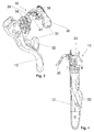
figure 1 is a perspective view of a first embodiment of an actuation device for a control cable for a bicycle gearshift according to the invention, in particular it concerns an integrated brake-gearshift actuation device of a bicycle; -
figure 2 is a further perspective view, partially sectioned, of the device offigure 1 ; -
figures 3 and 4 are a perspective view and a side view of part of the device offigure 1 , without a casing of the device; -
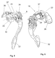
figures 5 and 6 are perspective views of part of the device offigures 4 and5 , without a brake lever; -
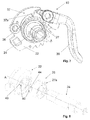
figure 7 is a perspective view of part of the device offigures 5 and 6 , without a first gearshift lever; -
figure 8 is an exploded perspective view of part of the device offigure 7 , without a second gearshift lever; -
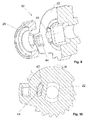
figures 9 and 10 are a cutaway perspective view and a cross section view - according to a plane perpendicular to the main axis of the device - of part of the device offigure 8 , in particular of a cable-winding bush and of an indexing bush; -
figures 11-14 are side and partially sectioned views (according to a plane perpendicular to the main axis of the device) of the device offigure 7 , which show successive positions during the operation of the device, in particular during an upward gearshifting; -
figure 15 is an exploded perspective view (analogous tofigure 8 ) of part of a second embodiment of an actuation device for a control cable for a bicycle gearshift according to the invention; -
figures 15a and 15b are perspective views of part of the device offigure 15 , in particular of a cable-winding bush and of an indexing bush; -
figure 16 is an exploded perspective view (analogous tofigure 15 ) of part of a third embodiment of an actuation device for a control cable for a bicycle gearshift according to the invention; -
figures 16a and 16b are perspective views of part of the device offigure 16 , in particular of a cable-winding bush and of an indexing bush, exploded (figure 16a ) and in cross section according to a plane perpendicular to the main axis of the device (figure 16b ); -
figure 17 is an exploded perspective view (analogous tofigure 16 ) of part of a fourth embodiment of an actuation device for a control cable for a bicycle gearshift according to the invention; -
figure 17a is a side view of part of the device offigure 17 , in particular of the assembly of indexing bush and rotation pin; -
figure 18 is an exploded perspective view (analogous tofigure 17 ) of part of a fifth embodiment of an actuation device for a control cable for a bicycle gearshift according to the invention; -
figures 18a, 18b and 18c are side views of part of the device offigure 18 , in particular of a cable-winding bush (figure 18a ), of an indexing bush (figure 18b ) and of the assembly of indexing bush and rotation pin (figure 18c ). - With initial reference to
figures 1-14 a first embodiment of actuation device for a control cable (not shown) for a gearshift of a bicycle in accordance with the present invention is shown. The actuation device is wholly indicated with 10. - In particular, in
figures 1 and 2 theactuation device 10 is included in an integrated brake-gearshift actuation device 100 of the bicycle. The integrated actuation device comprises, as well as theactuation device 10, an actuation device for a brake (not shown) of the bicycle.Figures 1-4 show abrake lever 12 included in the actuation device for the brake. - More specifically,
figures 1-14 show theactuation device 10 of the control cable for the rear derailleur of the bicycle. - With particular reference to
figures 1 and 2 , theactuation device 10 is mounted on bicycle handlebars (not shown), in particular of the type used on racing bicycles. - The
actuation device 10 comprises acasing 14, which is fixed to the handlebars in conventional manner, like for example a strap 16. Thecasing 14 comprises abody 18 extending along an axis A of thedevice 10. - As will be clear hereafter, the main axis A is the main reference axis for the elements that are part of the
device 10; all of the indications of direction and the like, such as "axial", "radial", "circumferential", "diametral" and the like will refer with respect to it; equally, the indications "outwards" and "inwards" referring to radial directions should be understood as away from the axis A or towards the axis A. Two opposite angular directions are also defined about the axis A, indicated with R and L, the first in the clockwise direction, the second in the anti-clockwise direction, observing thedevice 10 as represented infigure 10 . - The
device 10 comprises a cable-windingbush 22, to which the control cable is fixed and on which it is wound. The cable-windingbush 22 is mounted in thebody 18 of thecasing 14 and is angularly mobile about the axis A. - The cable-winding
bush 22 comprises arotation pin 24 arranged along the axis A. Therotation pin 24 is integral with the cable-windingbush 22. - The
rotation pin 24 is housed in a suitable rotation seat (not shown) made in thebody 18 of thecasing 14. - The
device 10 also comprises anindexing bush 26 that is coaxial to the cable-windingbush 22 and that is associated with it to removably hold the cable-windingbush 22 in predetermined angular positions with respect to thecasing 14, according to the selected transmission ratio of the gearshift. Such angular positions are angularly spaced apart each other by predetermined indexing angles α and are defined on theindexing bush 26 by a plurality of correspondingteeth 27 made on a radially outertoothed sector 27a of the indexing bush 26 (see in particularfigure 7 ). Preferably, theteeth 27 are angularly spaced apart each other by a same predetermined indexing angle α. - The
device 10 also comprises a manoeuvring mechanism, to obtain upward or downward gearshifting, wholly indicated with 30, operative on the cable-windingbush 22 to rotate it in the angular directions R and L about the axis A. - The
manoeuvring mechanism 30 comprises afirst gearshift lever 32, which is angularly mobile with respect to thecasing 14 about the axis A, in the angular direction R starting from a neutral position to obtain the upward gearshifting. - The
first gearshift lever 32 is connected to therotation pin 24 of the cable-windingbush 22. - Elastic means 34 are active between the
first gearshift lever 32 and thecasing 14, and suchelastic means 34 tend to take thefirst gearshift lever 32 again into the neutral position. - In the non-limiting example illustrated, such elastic means are a ring-shaped torsion spring 34 (see
figures 3 ,5 and 6 ), mounted in thecasing 14 coaxially to the axis A and constrained at one end to thecasing 14 and at the other end to thefirst gearshift lever 32. - The connection between
first gearshift lever 32 androtation pin 24 is per sé conventional and therefore will not be described in detail hereafter. - The
manoeuvring mechanism 30 comprises asecond gearshift lever 36, which acts on theindexing bush 26 to allow a rotation thereof, together with the cable-windingbush 22, in the angular direction L about the axis A, so as to obtain a downward gearshifting. - As shown in
figure 7 , thesecond gearshift lever 36 acts on arocker 37 hinged on apin 39 integral with the cable-windingbush 22. Therocker 37 comprises apawl 37a that acts on theteeth 27 of thetoothed sector 27a of theindexing bush 26. - In particular, by actuating the
second gearshift lever 36, therocker 37 is moved away from thetoothed sector 27a, so that thepawl 37a disengages from atooth 27. Once downward gearshifting has occurred, therocker 37 goes back towards thetoothed sector 27a through the effect ofelastic means 38, for example a torsion spring (for example arranged at such a pin 39), and thepawl 37a locks thenext tooth 27 in the angular direction L with respect to that which it has previously disengaged. - The downward gearshifting mechanism that uses the assembly of
second gearshift lever 36,rocker 37,pawl 37a andtoothed sector 27a is of the conventional type and is not specified any further. - In accordance with a characterising aspect of the invention, between the cable-winding
bush 22 and theindexing bush 26 it is provided acoupling 40 with a predeterminedcircumferential clearance 42, corresponding to a predetermined gearshifting extra-stroke angle β. - The
coupling 40 makes it possible to obtain the desired gearshifting extra-stroke during the upward gearshifting, obtained by actuating thefirst gearshift lever 32. - In particular, with reference to
figures 11-14 , thefirst gearshift lever 32 acts on the cable-windingbush 22 so as to: - (i) impose a first rotation of the cable-winding
bush 22 with respect to thecasing 14 and to theindexing bush 26 in the angular direction R by the predetermined gearshifting extra-stroke angle β (figure 12 ), - (ii) impose a second rotation of the cable-winding
bush 22 with respect to thecasing 14, together with theindexing bush 26, in the angular direction R by the respective predetermined indexing angle α (figure 13 ), and - (iii) allow a third rotation of the cable-winding
bush 22 with respect to thecasing 14 and to theindexing bush 26 in the angular direction L - opposite to the angular direction R - by the predetermined gearshifting extra-stroke angle β (figure 14 ). - As shown in
figures 8-14 , thecoupling 40 between the cable-windingbush 22 and theindexing bush 26 comprises aprotrusion 44, protruding in axial direction and in position eccentric from the cable-windingbush 22, and acorresponding recess 46, axially formed in theindexing bush 26. The predeterminedcircumferential clearance 42 is provided between therecess 46 and theprotrusion 44. -
Figures 15, 15a and 15b show a second embodiment of theactuation device 10 according to the invention. In such figures, structural elements that are identical or equivalent from the functional point of view to those of the first embodiment of thedevice 10 of the invention (figures 1-14 ) will be attributed the same reference numerals and they will not be described any further. - In particular, the second embodiment of the
device 10 differs from the first embodiment of thedevice 10 in that thecoupling 40 between the cable-windingbush 22 and theindexing bush 26 comprises aprotrusion 144, protruding in axial direction and in position eccentric from the cable-windingbush 22, and acorresponding recess 146, axially formed in theindexing bush 26. The predeterminedcircumferential clearance 42 is provide between therecess 146 and theprotrusion 144. -
Figures 16, 16a and 16b show a third embodiment of theactuation device 10 according to the invention. In such figures, structural elements that are identical or equivalent from the functional point of view to those of the first embodiment of thedevice 10 of the invention (figures 1-14 ) will be attributed the same reference numerals and they will not be described any further. - In particular, the third embodiment of the
device 10 differs from the first embodiment of thedevice 10 in that thecoupling 40 between the cable-windingbush 22 and theindexing bush 26 comprises a plurality ofprotrusions 244, protruding in axial direction and in a same position eccentric from the cable-windingbush 22, and a plurality ofprotrusions 248, protruding in axial direction and in a same position eccentric from theindexing bush 26. - A plurality of
insertion spaces 250 for theprotrusions 248 are defined between theprotrusions 244, just as a plurality ofinsertion spaces 252 for theprotrusions 244 are defined between theprotrusions 248. Theinsertion spaces respective protrusions circumferential clearance 42 is provided between the cable-windingbush 22 and theindexing bush 26. - Preferably, all of the protrusions 244 (and all of the corresponding insertion spaces 252) have equal circumferential extension, just as all of the protrusions 248 (and all of the corresponding insertion spaces 250) have equal circumferential extension.
- More preferably, all of the
protrusions 244 have an equal circumferential extension that is equivalent to the equal circumferential extension of all of theprotrusions 248, just as all of theinsertion spaces 252 have an equal circumferential extension that is equivalent to the equal circumferential extension of all of theinsertion spaces 250. - Basically, the
protrusions 244 with theinsertion spaces 250 and theprotrusions 248 with theinsertion spaces 252 define a pair ofaxial toothings bush 22 and of theindexing bush 26, respectively, which engage with each other with the predeterminedcircumferential clearance 42. - In a variant that is not illustrated, the
insertion spaces bush 22 and in theindexing bush 26, respectively. In this case they become, in practice, receiving seats for at least part of theprotrusions -
Figures 17 and 17a show a fourth embodiment of theactuation device 10 according to the invention. In such figures, structural elements that are identical or equivalent from the functional point of view to those of the first embodiment of thedevice 10 of the invention (figures 1-14 ) will be attributed the same reference numerals and they will not be described any further. - In particular, the fourth embodiment of the
device 10 differs from the first embodiment of thedevice 10 in that thecoupling 40 between the cable-windingbush 22 and theindexing bush 26 comprises aprotrusion 344, radially protruding from therotation pin 24, and acorresponding recess 346, radially formed in theindexing bush 26. The predeterminedcircumferential clearance 42 is provided between therecess 346 and theprotrusion 344. It is worth repeating that therotation pin 24 is integral with the cable-windingbush 22. - The
protrusion 344 and therecess 346 extend along an arc of circumference having centre substantially on the axis A. - In a variant that is not illustrated, the
coupling 40 between the cable-windingbush 22 and theindexing bush 26 comprises a protrusion, radially protruding from a substantially circular hole of the indexing bush 26 (at least one portion of the rotation pin being inserted into such a hole), and a corresponding recess, radially formed in therotation pin 24. The predetermined circumferential clearance is provided between the aforementioned recess and the aforementioned protrusion. -
Figures 18 and 18a-18c show a fifth embodiment of theactuation device 10 according to the invention. In such figures, structural elements that are identical or equivalent from the functional point of view to those of the first embodiment of thedevice 10 of the invention (figures 1-14 ) will be attributed the same reference numerals and they will not be described any further. - In particular, the fifth embodiment of the
device 10 differs from the first embodiment of thedevice 10 in that thecoupling 40 between the cable-windingbush 22 and theindexing bush 26 comprises a shapedhole 454 of theindexing bush 26 that extends axially and a corresponding shapedportion 456 of therotation pin 24, in which the predeterminedcircumferential clearance 42 is provided between theshaped hole 454 and the shapedportion 456. - As shown in particular in
figure 18c , the shapedportion 456 has substantially quadrilateral cross section, with a pair ofopposite sides 456a that are substantially rectilinear and parallel. The other pair ofopposite sides 456b of the shapedportion 456 is shaped like an arc of circumference having centre substantially on the axis A. - As shown in particular in
figures 18b and 18c , the shapedhole 454 has substantially quadrilateral cross section, with a pair ofopposite sides 454a that cooperate with clearance with the pair ofopposite sides 456a of the shaped portion 456 (so as to allow a relative rotation between shapedportion 456 and shapedhole 454, which corresponds to the predetermined circumferential clearance 42). The other pair ofopposite sides 454b of the shapedhole 454 is shaped like an arc of circumference having centre substantially on the axis A and slidingly cooperates with the pair ofopposite sides 456b of the shapedportion 456. - The operation of the
actuation device 10 according to the invention is already clear from the above and is totally analogous for all of the embodiments and variants described. It is further specified hereafter, in reference to the first embodiment (figures 11-14 ), that of the other embodiments and variants being totally analogous. - Thanks to the
coupling 40 with the predeterminedcircumferential clearance 42 the following operation in steps of theactuation device 10 according to the invention is obtained. - In a first actuation step of the
first gearshift lever 32, the cable-windingbush 22 rotates by the predetermined gearshifting extra-stroke angle β whereas theindexing bush 26 stays immobile (with respect to the casing 14) thanks to the predeterminedcircumferential clearance 42 of the coupling 40 (figure 12 ). - Thereafter the
protrusion 44 goes into abutment in therecess 46 so that the cable-windingbush 22 pulls theindexing bush 26 by an angular stroke equal to the respective predetermined indexing angle α (figure 13 ). - The transmission chain follows the cable-winding
bush 22 and thus so far it has already travelled an extra space (extra-stroke) with respect to the indexing stroke, i.e. corresponding to the angular stroke corresponding to the gearshifting extra-stroke angle β added to the respective indexing angle α. In other words the transmission chain is not in a position of ordinary engagement of the next larger toothed wheel, but further forward (extra-stroke) by a distance corresponding to the gearshifting extra-stroke angle β. - Thereafter there is the release of the
first gearshift lever 32 and the cable-windingbush 22 goes back by the gearshifting extra-stroke angle β, whereas theindexing bush 26 stays immobile (with respect to the casing 14) again thanks to the predetermined circumferential clearance betweenprotrusion 44 and recess 46 (figure 14 ). - In this way the transmission chain, which follows the rotation of the cable-winding
bush 22, after having been in extra-stroke position during the gearshifting (figure 13 ), goes back by a stroke corresponding to the gearshifting extra-stroke angle β up to the position of ordinary engagement of the next larger toothed wheel. - Therefore, thanks to the
coupling 40 with the predeterminedcircumferential clearance 42, an excellent reliability of the upward gearshifting is obtained in simple and effective manner, ensuring that the transmission chain that must engage the next larger toothed wheel moves by an extra-stroke with respect to the only indexing stroke, which is then recovered at the end of gearshifting, so that the transmission chain remains exactly in the engagement position of the larger toothed wheel (indexing position). - Basically, in the aforementioned three steps, the cable-winding
bush 22 carries out a first rotation in the angular direction R by the predetermined gearshifting extra-stroke angle β (figure 12 ), then carries out a second rotation in the angular direction R by the respective predetermined indexing angle α (figure 13 ), and finally carries out a third rotation in the angular direction L by the predetermined gearshifting extra-stroke angle β (figure 14 ). - It should be observed that, once the upward gearshifting has occurred, the
pawl 37a of therocker 37 locks the tooth 27 (of thetoothed sector 27a of the indexing bush 26) that is next in the angular direction R with respect to that at which it was engaged before the gearshifting that had disengaged before (infigures 11 and 12 thepawl 27 engages thesecond tooth 27, whereas infigures 13 and 14 thepawl 37a engages thethird tooth 27, i.e. the next tooth in the angular direction R). The passage of thepawl 37a between the twoteeth 27 is carried out substantially automatically thanks to the asymmetric shape (substantially sawtooth) of the profile of theteeth 27 themselves and of thepawl 37a (as well as by the elastic means 38 that pull back therocker 37 towards thetoothed sector 27a). Such passage is of conventional type and is not specified any further. Preferably, the predetermined gearshifting extra-stroke angle β is greater than zero and less than or equal to the minimum value among the predetermined indexing angles α. For example, in the case of an indexing angle of 13.6° the gearshifting extra-stroke angle can be of 5°. - Of course, those skilled in the art can bring numerous modifications and variants to the invention described above in order to satisfy specific and contingent requirements, all of which are in any case encompassed by the scope of protection as defined by the following claims.
Claims (14)
- Actuation device (10) for a control cable for a bicycle gearshift, comprising:- a casing (14), configured for fixing to bicycle handlebars,- a cable-winding bush (22), on which the control cable is wound and which is angularly mobile in the casing (14) about a main axis (A) of the device (10),- an indexing bush (26) coaxial to the cable-winding bush (22) and associated with it to removably hold the cable-winding bush (22) in predetermined angular positions, angularly spaced apart each other by predetermined indexing angles (α),- a manoeuvring mechanism (30), operative on the cable-winding bush (22) to rotate it in a first angular direction (R) about the main axis (A) of the device (10), to obtain an upward gearshifting,characterised in that between the cable-winding bush (22) and the indexing bush (26) it is provided a coupling (40) with a predetermined circumferential clearance (42) corresponding to a predetermined gearshifting extra-stroke angle (β).
- Device (10) according to claim 1, wherein the manoeuvring mechanism (30) comprises a first gearshift lever (32), which is angularly mobile with respect to the casing (14) about the main axis (A) of the device (10), in the first angular direction (R) starting from a neutral position to obtain the upward gearshifting,
wherein the first gearshift lever (32) acts on the cable-winding bush so as to:(i) impose a first rotation of the cable-winding bush (22) with respect to the casing (14) and to the indexing bush (26) in the first angular direction (R) by the predetermined gearshifting extra-stroke angle (β),(ii) impose a second rotation of the cable-winding bush (22) with respect to the casing (14), together with the indexing bush (26), in the first angular direction (R) by the respective predetermined indexing angle (α), and(iii) allow a third rotation of the cable-winding bush (22) with respect to the casing (14) and to the indexing bush (26) in a second angular direction (L) opposite to the first angular direction (R) by the predetermined gearshifting extra-stroke angle (β). - Device (10) according to claim 2, wherein elastic means (34) are active between the first gearshift lever (32) and the casing (14), wherein said elastic means (34) tend to take the first gearshift lever (32) again into the neutral position.
- Device (10) according to claim 2 or 3, wherein the cable-winding bush (22) comprises a rotation pin (24) arranged along the main axis (A) of the device (10).
- Device (10) according to any one of the previous claims, wherein the coupling (40) between the cable-winding bush (22) and the indexing bush (26) comprises at least one protrusion (44, 144), protruding in axial direction and in eccentric position from the indexing bush (26) or from the cable-winding bush (22), and at least one corresponding recess (46, 146), axially formed in the cable-winding bush (22) or in the indexing bush (26), respectively, wherein the predetermined circumferential clearance (42) is provided between the at least one recess (46, 146) and the at least one protrusion (44, 144).
- Device (10) according to claim 4, wherein the coupling (40) between the cable-winding bush (22) and the indexing bush (26) comprises at least one protrusion (344), protruding radially from the rotation pin (24), and at least one corresponding recess (346), formed radially in the indexing bush (26), wherein the predetermined circumferential clearance is provided between the at least one recess (346) and the at least one protrusion (344).
- Device (10) according to claim 5 or 6, wherein the at least one protrusion (44, 144, 344) and the at least one recess (46, 146, 346) extend along an arc of circumference having centre substantially on the main axis (A) of the device (10).
- Device (10) according to any one of claims 1 to 4, wherein the coupling (40) between the cable-winding bush (22) and the indexing bush (26) comprises a pair of axial toothings (251, 253) of the cable-winding bush (22) and of the indexing bush (26), respectively, which mutually engage with the predetermined circumferential clearance (42).
- Device (10) according to claim 4, wherein the coupling (40) between the cable-winding bush (22) and the indexing bush (26) comprises a shaped hole (454) of the indexing bush (26) that extends axially and a corresponding shaped portion (456) of the rotation pin (24), wherein the predetermined circumferential clearance (42) is provided between the shaped hole (454) and the shaped portion (456).
- Device (10) according to claim 9, wherein the shaped portion (456) has substantially quadrilateral cross section, with a pair of opposite sides (456a) that are substantially rectilinear and parallel.
- Device (10) according to claim 10, wherein the shaped portion (456) has the other pair of opposite sides (456b) shaped like an arc of circumference having centre substantially on the main axis (A) of the device (10).
- Device (10) according to any one of the previous claims, wherein the manoeuvring mechanism (30) comprises a second gearshift lever (36), which acts on the indexing bush (26) to allow a rotation thereof, together with the cable-winding bush (22), in the second angular direction (L) about the main axis (A) of the device (10), so as to obtain a downward gearshifting.
- Device (10) according to any one of the previous claims, wherein the predetermined gearshifting extra-stroke angle (β) is greater than zero and less than or equal to the minimum value among the predetermined indexing angles (a).
- Integrated brake-gearshift actuation device (100) of a bicycle, comprising an actuation device for a bicycle brake and an actuation device (10) for a control cable for a gearshift of the bicycle according to any one of the previous claims.
Applications Claiming Priority (1)
| Application Number | Priority Date | Filing Date | Title |
|---|---|---|---|
| ITUB20151309 | 2015-06-04 |
Publications (2)
| Publication Number | Publication Date |
|---|---|
| EP3100942A1 true EP3100942A1 (en) | 2016-12-07 |
| EP3100942B1 EP3100942B1 (en) | 2019-07-10 |
Family
ID=53794442
Family Applications (1)
| Application Number | Title | Priority Date | Filing Date |
|---|---|---|---|
| EP16171322.7A Active EP3100942B1 (en) | 2015-06-04 | 2016-05-25 | Actuation device for a control cable for a bicycle gearshift |
Country Status (4)
| Country | Link |
|---|---|
| EP (1) | EP3100942B1 (en) |
| JP (1) | JP6771316B2 (en) |
| CN (1) | CN106240734B (en) |
| TW (1) | TWI719987B (en) |
Cited By (1)
| Publication number | Priority date | Publication date | Assignee | Title |
|---|---|---|---|---|
| IT201700015349A1 (en) * | 2017-02-13 | 2018-08-13 | Campagnolo Srl | Device for operating the front derailleur of a bicycle |
Families Citing this family (2)
| Publication number | Priority date | Publication date | Assignee | Title |
|---|---|---|---|---|
| IT201700015361A1 (en) * | 2017-02-13 | 2018-08-13 | Campagnolo Srl | Mechanical device for operating the control cable of a bicycle derailleur |
| IT201700085704A1 (en) * | 2017-07-26 | 2019-01-26 | Campagnolo Srl | Operating device for a front derailleur of a bicycle |
Citations (3)
| Publication number | Priority date | Publication date | Assignee | Title |
|---|---|---|---|---|
| US3972247A (en) * | 1974-09-23 | 1976-08-03 | Armstrong Allen E | Bicycle shift mechanism |
| FR2657062A1 (en) * | 1990-01-12 | 1991-07-19 | Sachs Ind Sa | Operating device with indexing for a cycle derailleur |
| US5197927A (en) * | 1991-03-20 | 1993-03-30 | Sram Corporation | Bicycle derailleur cable actuating system |
Family Cites Families (15)
| Publication number | Priority date | Publication date | Assignee | Title |
|---|---|---|---|---|
| FR2467767A1 (en) * | 1979-10-19 | 1981-04-30 | Huret Roger | CONTROL KNOB FOR CYCLE DERAILLEUR |
| JPS59127127A (en) * | 1983-01-08 | 1984-07-21 | Shimano & Co Ltd | Variable speed operator |
| JPS63269795A (en) * | 1987-04-24 | 1988-11-08 | マエダ工業株式会社 | Variable speed operating lever device for bicycle |
| JPH0532190A (en) * | 1991-12-13 | 1993-02-09 | Shimano Inc | Shift operation device |
| JP2942850B2 (en) * | 1994-08-02 | 1999-08-30 | 信夫 小崎 | Speed change device for bicycle |
| WO1996004167A1 (en) * | 1994-08-02 | 1996-02-15 | Nobuo Ozaki | Speed change operating device for bicycles |
| US5799542A (en) * | 1995-10-11 | 1998-09-01 | Shimano, Inc. | Bicycle shift control device |
| US5921140A (en) * | 1996-04-04 | 1999-07-13 | Fichtel & Sachs Ag | Index shifter for a bicycle transmission and a method of making an index shifter for a bicycle transmission |
| US7152498B2 (en) * | 2003-12-03 | 2006-12-26 | Shimano Inc. | Bicycle control cable fixing device |
| EP1564131B1 (en) * | 2004-02-06 | 2007-08-15 | Campagnolo S.R.L. | Actuation device for a control cable for a bicycle gearshift |
| US7650813B2 (en) * | 2005-05-19 | 2010-01-26 | Shimano Inc. | Position control mechanism for bicycle control device |
| ATE486772T1 (en) * | 2005-08-04 | 2010-11-15 | Campagnolo Srl | ACTUATING METHOD AND DEVICE FOR THE ACTUATING CABLE OF A BICYCLE GEARSHIFT |
| US20070068312A1 (en) * | 2005-09-07 | 2007-03-29 | Shimano Inc. | Bicycle shift control mechanism |
| EP2468614B1 (en) * | 2010-12-03 | 2013-10-02 | Campagnolo S.r.l. | Actuation device for a control cable for a bicycle gearshift |
| US8869649B2 (en) * | 2011-07-12 | 2014-10-28 | Shimano Inc. | Bicycle shift operating device |
-
2016
- 2016-05-25 EP EP16171322.7A patent/EP3100942B1/en active Active
- 2016-05-27 TW TW105116695A patent/TWI719987B/en active
- 2016-06-01 JP JP2016109950A patent/JP6771316B2/en active Active
- 2016-06-06 CN CN201610393253.9A patent/CN106240734B/en active Active
Patent Citations (4)
| Publication number | Priority date | Publication date | Assignee | Title |
|---|---|---|---|---|
| US3972247A (en) * | 1974-09-23 | 1976-08-03 | Armstrong Allen E | Bicycle shift mechanism |
| FR2657062A1 (en) * | 1990-01-12 | 1991-07-19 | Sachs Ind Sa | Operating device with indexing for a cycle derailleur |
| US5197927A (en) * | 1991-03-20 | 1993-03-30 | Sram Corporation | Bicycle derailleur cable actuating system |
| US5197927B1 (en) * | 1991-03-20 | 2000-10-17 | Sram Corp | Bicycle derailleur cable actuating system |
Cited By (3)
| Publication number | Priority date | Publication date | Assignee | Title |
|---|---|---|---|---|
| IT201700015349A1 (en) * | 2017-02-13 | 2018-08-13 | Campagnolo Srl | Device for operating the front derailleur of a bicycle |
| EP3360765A1 (en) * | 2017-02-13 | 2018-08-15 | Campagnolo S.r.l. | Device for actuating the front derailleur of a bicycle |
| US10160515B2 (en) | 2017-02-13 | 2018-12-25 | Campagnolo S.R.L. | Device for actuating the front derailleur of a bicycle |
Also Published As
| Publication number | Publication date |
|---|---|
| TW201704088A (en) | 2017-02-01 |
| TWI719987B (en) | 2021-03-01 |
| EP3100942B1 (en) | 2019-07-10 |
| CN106240734B (en) | 2020-07-28 |
| JP2017013780A (en) | 2017-01-19 |
| CN106240734A (en) | 2016-12-21 |
| JP6771316B2 (en) | 2020-10-21 |
Similar Documents
| Publication | Publication Date | Title |
|---|---|---|
| US9802671B2 (en) | Control device for a bicycle derailleur | |
| EP1955937B2 (en) | Control device for a derailleur of a bicycle | |
| EP1724189B1 (en) | Position control mechanism for bicycle control device | |
| US9266581B2 (en) | Actuation device for a control cable for a bicycle gearshift | |
| EP1762485B1 (en) | Bicycle shift control mechanism | |
| EP2578487B1 (en) | Bicycle front derailleur with a variable actuation ratio | |
| EP3100942B1 (en) | Actuation device for a control cable for a bicycle gearshift | |
| US10442499B2 (en) | Actuation device for the control cable of a bicycle gearshift | |
| EP2189363B1 (en) | Cable operating mechanism | |
| JP4040059B2 (en) | Bicycle shifting operation device | |
| US10946934B2 (en) | Actuation device for a control cable for a bicycle gearshift | |
| US20090124440A1 (en) | Gear changing mechanism for chain drive | |
| TWI729154B (en) | Actuation device of the control cable of a front derailleur of a bicycle | |
| CN109305284B (en) | Actuating device for actuating a front derailleur of a bicycle |
Legal Events
| Date | Code | Title | Description |
|---|---|---|---|
| PUAI | Public reference made under article 153(3) epc to a published international application that has entered the european phase |
Free format text: ORIGINAL CODE: 0009012 |
|
| STAA | Information on the status of an ep patent application or granted ep patent |
Free format text: STATUS: THE APPLICATION HAS BEEN PUBLISHED |
|
| AK | Designated contracting states |
Kind code of ref document: A1 Designated state(s): AL AT BE BG CH CY CZ DE DK EE ES FI FR GB GR HR HU IE IS IT LI LT LU LV MC MK MT NL NO PL PT RO RS SE SI SK SM TR |
|
| AX | Request for extension of the european patent |
Extension state: BA ME |
|
| STAA | Information on the status of an ep patent application or granted ep patent |
Free format text: STATUS: REQUEST FOR EXAMINATION WAS MADE |
|
| 17P | Request for examination filed |
Effective date: 20170607 |
|
| RBV | Designated contracting states (corrected) |
Designated state(s): AL AT BE BG CH CY CZ DE DK EE ES FI FR GB GR HR HU IE IS IT LI LT LU LV MC MK MT NL NO PL PT RO RS SE SI SK SM TR |
|
| STAA | Information on the status of an ep patent application or granted ep patent |
Free format text: STATUS: EXAMINATION IS IN PROGRESS |
|
| 17Q | First examination report despatched |
Effective date: 20180102 |
|
| REG | Reference to a national code |
Ref country code: DE Ref legal event code: R079 Ref document number: 602016016543 Country of ref document: DE Free format text: PREVIOUS MAIN CLASS: B62M0025000000 Ipc: B62K0023060000 |
|
| GRAP | Despatch of communication of intention to grant a patent |
Free format text: ORIGINAL CODE: EPIDOSNIGR1 |
|
| STAA | Information on the status of an ep patent application or granted ep patent |
Free format text: STATUS: GRANT OF PATENT IS INTENDED |
|
| RIC1 | Information provided on ipc code assigned before grant |
Ipc: B62K 23/06 20060101AFI20181030BHEP Ipc: B62L 3/02 20060101ALI20181030BHEP |
|
| INTG | Intention to grant announced |
Effective date: 20181203 |
|
| GRAS | Grant fee paid |
Free format text: ORIGINAL CODE: EPIDOSNIGR3 |
|
| GRAA | (expected) grant |
Free format text: ORIGINAL CODE: 0009210 |
|
| STAA | Information on the status of an ep patent application or granted ep patent |
Free format text: STATUS: THE PATENT HAS BEEN GRANTED |
|
| AK | Designated contracting states |
Kind code of ref document: B1 Designated state(s): AL AT BE BG CH CY CZ DE DK EE ES FI FR GB GR HR HU IE IS IT LI LT LU LV MC MK MT NL NO PL PT RO RS SE SI SK SM TR |
|
| REG | Reference to a national code |
Ref country code: GB Ref legal event code: FG4D |
|
| REG | Reference to a national code |
Ref country code: CH Ref legal event code: EP Ref country code: AT Ref legal event code: REF Ref document number: 1153288 Country of ref document: AT Kind code of ref document: T Effective date: 20190715 |
|
| REG | Reference to a national code |
Ref country code: IE Ref legal event code: FG4D |
|
| REG | Reference to a national code |
Ref country code: DE Ref legal event code: R096 Ref document number: 602016016543 Country of ref document: DE |
|
| REG | Reference to a national code |
Ref country code: NL Ref legal event code: MP Effective date: 20190710 |
|
| REG | Reference to a national code |
Ref country code: LT Ref legal event code: MG4D |
|
| REG | Reference to a national code |
Ref country code: AT Ref legal event code: MK05 Ref document number: 1153288 Country of ref document: AT Kind code of ref document: T Effective date: 20190710 |
|
| PG25 | Lapsed in a contracting state [announced via postgrant information from national office to epo] |
Ref country code: LT Free format text: LAPSE BECAUSE OF FAILURE TO SUBMIT A TRANSLATION OF THE DESCRIPTION OR TO PAY THE FEE WITHIN THE PRESCRIBED TIME-LIMIT Effective date: 20190710 Ref country code: PT Free format text: LAPSE BECAUSE OF FAILURE TO SUBMIT A TRANSLATION OF THE DESCRIPTION OR TO PAY THE FEE WITHIN THE PRESCRIBED TIME-LIMIT Effective date: 20191111 Ref country code: FI Free format text: LAPSE BECAUSE OF FAILURE TO SUBMIT A TRANSLATION OF THE DESCRIPTION OR TO PAY THE FEE WITHIN THE PRESCRIBED TIME-LIMIT Effective date: 20190710 Ref country code: NL Free format text: LAPSE BECAUSE OF FAILURE TO SUBMIT A TRANSLATION OF THE DESCRIPTION OR TO PAY THE FEE WITHIN THE PRESCRIBED TIME-LIMIT Effective date: 20190710 Ref country code: BG Free format text: LAPSE BECAUSE OF FAILURE TO SUBMIT A TRANSLATION OF THE DESCRIPTION OR TO PAY THE FEE WITHIN THE PRESCRIBED TIME-LIMIT Effective date: 20191010 Ref country code: SE Free format text: LAPSE BECAUSE OF FAILURE TO SUBMIT A TRANSLATION OF THE DESCRIPTION OR TO PAY THE FEE WITHIN THE PRESCRIBED TIME-LIMIT Effective date: 20190710 Ref country code: HR Free format text: LAPSE BECAUSE OF FAILURE TO SUBMIT A TRANSLATION OF THE DESCRIPTION OR TO PAY THE FEE WITHIN THE PRESCRIBED TIME-LIMIT Effective date: 20190710 Ref country code: AT Free format text: LAPSE BECAUSE OF FAILURE TO SUBMIT A TRANSLATION OF THE DESCRIPTION OR TO PAY THE FEE WITHIN THE PRESCRIBED TIME-LIMIT Effective date: 20190710 Ref country code: NO Free format text: LAPSE BECAUSE OF FAILURE TO SUBMIT A TRANSLATION OF THE DESCRIPTION OR TO PAY THE FEE WITHIN THE PRESCRIBED TIME-LIMIT Effective date: 20191010 |
|
| PG25 | Lapsed in a contracting state [announced via postgrant information from national office to epo] |
Ref country code: IS Free format text: LAPSE BECAUSE OF FAILURE TO SUBMIT A TRANSLATION OF THE DESCRIPTION OR TO PAY THE FEE WITHIN THE PRESCRIBED TIME-LIMIT Effective date: 20191110 Ref country code: ES Free format text: LAPSE BECAUSE OF FAILURE TO SUBMIT A TRANSLATION OF THE DESCRIPTION OR TO PAY THE FEE WITHIN THE PRESCRIBED TIME-LIMIT Effective date: 20190710 Ref country code: GR Free format text: LAPSE BECAUSE OF FAILURE TO SUBMIT A TRANSLATION OF THE DESCRIPTION OR TO PAY THE FEE WITHIN THE PRESCRIBED TIME-LIMIT Effective date: 20191011 Ref country code: LV Free format text: LAPSE BECAUSE OF FAILURE TO SUBMIT A TRANSLATION OF THE DESCRIPTION OR TO PAY THE FEE WITHIN THE PRESCRIBED TIME-LIMIT Effective date: 20190710 Ref country code: AL Free format text: LAPSE BECAUSE OF FAILURE TO SUBMIT A TRANSLATION OF THE DESCRIPTION OR TO PAY THE FEE WITHIN THE PRESCRIBED TIME-LIMIT Effective date: 20190710 Ref country code: RS Free format text: LAPSE BECAUSE OF FAILURE TO SUBMIT A TRANSLATION OF THE DESCRIPTION OR TO PAY THE FEE WITHIN THE PRESCRIBED TIME-LIMIT Effective date: 20190710 |
|
| PG25 | Lapsed in a contracting state [announced via postgrant information from national office to epo] |
Ref country code: TR Free format text: LAPSE BECAUSE OF FAILURE TO SUBMIT A TRANSLATION OF THE DESCRIPTION OR TO PAY THE FEE WITHIN THE PRESCRIBED TIME-LIMIT Effective date: 20190710 |
|
| PG25 | Lapsed in a contracting state [announced via postgrant information from national office to epo] |
Ref country code: PL Free format text: LAPSE BECAUSE OF FAILURE TO SUBMIT A TRANSLATION OF THE DESCRIPTION OR TO PAY THE FEE WITHIN THE PRESCRIBED TIME-LIMIT Effective date: 20190710 Ref country code: EE Free format text: LAPSE BECAUSE OF FAILURE TO SUBMIT A TRANSLATION OF THE DESCRIPTION OR TO PAY THE FEE WITHIN THE PRESCRIBED TIME-LIMIT Effective date: 20190710 Ref country code: DK Free format text: LAPSE BECAUSE OF FAILURE TO SUBMIT A TRANSLATION OF THE DESCRIPTION OR TO PAY THE FEE WITHIN THE PRESCRIBED TIME-LIMIT Effective date: 20190710 Ref country code: RO Free format text: LAPSE BECAUSE OF FAILURE TO SUBMIT A TRANSLATION OF THE DESCRIPTION OR TO PAY THE FEE WITHIN THE PRESCRIBED TIME-LIMIT Effective date: 20190710 |
|
| PG25 | Lapsed in a contracting state [announced via postgrant information from national office to epo] |
Ref country code: SM Free format text: LAPSE BECAUSE OF FAILURE TO SUBMIT A TRANSLATION OF THE DESCRIPTION OR TO PAY THE FEE WITHIN THE PRESCRIBED TIME-LIMIT Effective date: 20190710 Ref country code: SK Free format text: LAPSE BECAUSE OF FAILURE TO SUBMIT A TRANSLATION OF THE DESCRIPTION OR TO PAY THE FEE WITHIN THE PRESCRIBED TIME-LIMIT Effective date: 20190710 Ref country code: IS Free format text: LAPSE BECAUSE OF FAILURE TO SUBMIT A TRANSLATION OF THE DESCRIPTION OR TO PAY THE FEE WITHIN THE PRESCRIBED TIME-LIMIT Effective date: 20200224 Ref country code: CZ Free format text: LAPSE BECAUSE OF FAILURE TO SUBMIT A TRANSLATION OF THE DESCRIPTION OR TO PAY THE FEE WITHIN THE PRESCRIBED TIME-LIMIT Effective date: 20190710 |
|
| REG | Reference to a national code |
Ref country code: DE Ref legal event code: R097 Ref document number: 602016016543 Country of ref document: DE |
|
| PLBE | No opposition filed within time limit |
Free format text: ORIGINAL CODE: 0009261 |
|
| STAA | Information on the status of an ep patent application or granted ep patent |
Free format text: STATUS: NO OPPOSITION FILED WITHIN TIME LIMIT |
|
| PG2D | Information on lapse in contracting state deleted |
Ref country code: IS |
|
| 26N | No opposition filed |
Effective date: 20200603 |
|
| PG25 | Lapsed in a contracting state [announced via postgrant information from national office to epo] |
Ref country code: SI Free format text: LAPSE BECAUSE OF FAILURE TO SUBMIT A TRANSLATION OF THE DESCRIPTION OR TO PAY THE FEE WITHIN THE PRESCRIBED TIME-LIMIT Effective date: 20190710 |
|
| PG25 | Lapsed in a contracting state [announced via postgrant information from national office to epo] |
Ref country code: CH Free format text: LAPSE BECAUSE OF NON-PAYMENT OF DUE FEES Effective date: 20200531 Ref country code: LI Free format text: LAPSE BECAUSE OF NON-PAYMENT OF DUE FEES Effective date: 20200531 Ref country code: MC Free format text: LAPSE BECAUSE OF FAILURE TO SUBMIT A TRANSLATION OF THE DESCRIPTION OR TO PAY THE FEE WITHIN THE PRESCRIBED TIME-LIMIT Effective date: 20190710 |
|
| REG | Reference to a national code |
Ref country code: BE Ref legal event code: MM Effective date: 20200531 |
|
| GBPC | Gb: european patent ceased through non-payment of renewal fee |
Effective date: 20200525 |
|
| PG25 | Lapsed in a contracting state [announced via postgrant information from national office to epo] |
Ref country code: LU Free format text: LAPSE BECAUSE OF NON-PAYMENT OF DUE FEES Effective date: 20200525 |
|
| PG25 | Lapsed in a contracting state [announced via postgrant information from national office to epo] |
Ref country code: IE Free format text: LAPSE BECAUSE OF NON-PAYMENT OF DUE FEES Effective date: 20200525 Ref country code: GB Free format text: LAPSE BECAUSE OF NON-PAYMENT OF DUE FEES Effective date: 20200525 |
|
| PG25 | Lapsed in a contracting state [announced via postgrant information from national office to epo] |
Ref country code: BE Free format text: LAPSE BECAUSE OF NON-PAYMENT OF DUE FEES Effective date: 20200531 |
|
| PG25 | Lapsed in a contracting state [announced via postgrant information from national office to epo] |
Ref country code: MT Free format text: LAPSE BECAUSE OF FAILURE TO SUBMIT A TRANSLATION OF THE DESCRIPTION OR TO PAY THE FEE WITHIN THE PRESCRIBED TIME-LIMIT Effective date: 20190710 Ref country code: CY Free format text: LAPSE BECAUSE OF FAILURE TO SUBMIT A TRANSLATION OF THE DESCRIPTION OR TO PAY THE FEE WITHIN THE PRESCRIBED TIME-LIMIT Effective date: 20190710 |
|
| PG25 | Lapsed in a contracting state [announced via postgrant information from national office to epo] |
Ref country code: MK Free format text: LAPSE BECAUSE OF FAILURE TO SUBMIT A TRANSLATION OF THE DESCRIPTION OR TO PAY THE FEE WITHIN THE PRESCRIBED TIME-LIMIT Effective date: 20190710 |
|
| P01 | Opt-out of the competence of the unified patent court (upc) registered |
Effective date: 20230518 |
|
| PGFP | Annual fee paid to national office [announced via postgrant information from national office to epo] |
Ref country code: IT Payment date: 20230519 Year of fee payment: 8 Ref country code: FR Payment date: 20230525 Year of fee payment: 8 Ref country code: DE Payment date: 20230530 Year of fee payment: 8 |