EP3100924B1 - Method and apparatus for controlling plug-in hybrid electric vehicle, as well as computer-readable medium - Google Patents
Method and apparatus for controlling plug-in hybrid electric vehicle, as well as computer-readable medium Download PDFInfo
- Publication number
- EP3100924B1 EP3100924B1 EP15191961.0A EP15191961A EP3100924B1 EP 3100924 B1 EP3100924 B1 EP 3100924B1 EP 15191961 A EP15191961 A EP 15191961A EP 3100924 B1 EP3100924 B1 EP 3100924B1
- Authority
- EP
- European Patent Office
- Prior art keywords
- controller
- electric vehicle
- plug
- hybrid electric
- duc
- Prior art date
- Legal status (The legal status is an assumption and is not a legal conclusion. Google has not performed a legal analysis and makes no representation as to the accuracy of the status listed.)
- Active
Links
Images



Classifications
-
- B—PERFORMING OPERATIONS; TRANSPORTING
- B60—VEHICLES IN GENERAL
- B60W—CONJOINT CONTROL OF VEHICLE SUB-UNITS OF DIFFERENT TYPE OR DIFFERENT FUNCTION; CONTROL SYSTEMS SPECIALLY ADAPTED FOR HYBRID VEHICLES; ROAD VEHICLE DRIVE CONTROL SYSTEMS FOR PURPOSES NOT RELATED TO THE CONTROL OF A PARTICULAR SUB-UNIT
- B60W20/00—Control systems specially adapted for hybrid vehicles
- B60W20/10—Controlling the power contribution of each of the prime movers to meet required power demand
-
- B—PERFORMING OPERATIONS; TRANSPORTING
- B60—VEHICLES IN GENERAL
- B60W—CONJOINT CONTROL OF VEHICLE SUB-UNITS OF DIFFERENT TYPE OR DIFFERENT FUNCTION; CONTROL SYSTEMS SPECIALLY ADAPTED FOR HYBRID VEHICLES; ROAD VEHICLE DRIVE CONTROL SYSTEMS FOR PURPOSES NOT RELATED TO THE CONTROL OF A PARTICULAR SUB-UNIT
- B60W50/00—Details of control systems for road vehicle drive control not related to the control of a particular sub-unit, e.g. process diagnostic or vehicle driver interfaces
- B60W50/0097—Predicting future conditions
-
- B—PERFORMING OPERATIONS; TRANSPORTING
- B60—VEHICLES IN GENERAL
- B60W—CONJOINT CONTROL OF VEHICLE SUB-UNITS OF DIFFERENT TYPE OR DIFFERENT FUNCTION; CONTROL SYSTEMS SPECIALLY ADAPTED FOR HYBRID VEHICLES; ROAD VEHICLE DRIVE CONTROL SYSTEMS FOR PURPOSES NOT RELATED TO THE CONTROL OF A PARTICULAR SUB-UNIT
- B60W10/00—Conjoint control of vehicle sub-units of different type or different function
- B60W10/24—Conjoint control of vehicle sub-units of different type or different function including control of energy storage means
- B60W10/26—Conjoint control of vehicle sub-units of different type or different function including control of energy storage means for electrical energy, e.g. batteries or capacitors
-
- B—PERFORMING OPERATIONS; TRANSPORTING
- B60—VEHICLES IN GENERAL
- B60K—ARRANGEMENT OR MOUNTING OF PROPULSION UNITS OR OF TRANSMISSIONS IN VEHICLES; ARRANGEMENT OR MOUNTING OF PLURAL DIVERSE PRIME-MOVERS IN VEHICLES; AUXILIARY DRIVES FOR VEHICLES; INSTRUMENTATION OR DASHBOARDS FOR VEHICLES; ARRANGEMENTS IN CONNECTION WITH COOLING, AIR INTAKE, GAS EXHAUST OR FUEL SUPPLY OF PROPULSION UNITS IN VEHICLES
- B60K35/00—Instruments specially adapted for vehicles; Arrangement of instruments in or on vehicles
- B60K35/20—Output arrangements, i.e. from vehicle to user, associated with vehicle functions or specially adapted therefor
- B60K35/28—Output arrangements, i.e. from vehicle to user, associated with vehicle functions or specially adapted therefor characterised by the type of the output information, e.g. video entertainment or vehicle dynamics information; characterised by the purpose of the output information, e.g. for attracting the attention of the driver
-
- B—PERFORMING OPERATIONS; TRANSPORTING
- B60—VEHICLES IN GENERAL
- B60W—CONJOINT CONTROL OF VEHICLE SUB-UNITS OF DIFFERENT TYPE OR DIFFERENT FUNCTION; CONTROL SYSTEMS SPECIALLY ADAPTED FOR HYBRID VEHICLES; ROAD VEHICLE DRIVE CONTROL SYSTEMS FOR PURPOSES NOT RELATED TO THE CONTROL OF A PARTICULAR SUB-UNIT
- B60W10/00—Conjoint control of vehicle sub-units of different type or different function
- B60W10/04—Conjoint control of vehicle sub-units of different type or different function including control of propulsion units
- B60W10/06—Conjoint control of vehicle sub-units of different type or different function including control of propulsion units including control of combustion engines
-
- B—PERFORMING OPERATIONS; TRANSPORTING
- B60—VEHICLES IN GENERAL
- B60W—CONJOINT CONTROL OF VEHICLE SUB-UNITS OF DIFFERENT TYPE OR DIFFERENT FUNCTION; CONTROL SYSTEMS SPECIALLY ADAPTED FOR HYBRID VEHICLES; ROAD VEHICLE DRIVE CONTROL SYSTEMS FOR PURPOSES NOT RELATED TO THE CONTROL OF A PARTICULAR SUB-UNIT
- B60W10/00—Conjoint control of vehicle sub-units of different type or different function
- B60W10/04—Conjoint control of vehicle sub-units of different type or different function including control of propulsion units
- B60W10/08—Conjoint control of vehicle sub-units of different type or different function including control of propulsion units including control of electric propulsion units, e.g. motors or generators
-
- B—PERFORMING OPERATIONS; TRANSPORTING
- B60—VEHICLES IN GENERAL
- B60W—CONJOINT CONTROL OF VEHICLE SUB-UNITS OF DIFFERENT TYPE OR DIFFERENT FUNCTION; CONTROL SYSTEMS SPECIALLY ADAPTED FOR HYBRID VEHICLES; ROAD VEHICLE DRIVE CONTROL SYSTEMS FOR PURPOSES NOT RELATED TO THE CONTROL OF A PARTICULAR SUB-UNIT
- B60W20/00—Control systems specially adapted for hybrid vehicles
- B60W20/10—Controlling the power contribution of each of the prime movers to meet required power demand
- B60W20/12—Controlling the power contribution of each of the prime movers to meet required power demand using control strategies taking into account route information
-
- B—PERFORMING OPERATIONS; TRANSPORTING
- B60—VEHICLES IN GENERAL
- B60W—CONJOINT CONTROL OF VEHICLE SUB-UNITS OF DIFFERENT TYPE OR DIFFERENT FUNCTION; CONTROL SYSTEMS SPECIALLY ADAPTED FOR HYBRID VEHICLES; ROAD VEHICLE DRIVE CONTROL SYSTEMS FOR PURPOSES NOT RELATED TO THE CONTROL OF A PARTICULAR SUB-UNIT
- B60W20/00—Control systems specially adapted for hybrid vehicles
- B60W20/40—Controlling the engagement or disengagement of prime movers, e.g. for transition between prime movers
-
- B—PERFORMING OPERATIONS; TRANSPORTING
- B60—VEHICLES IN GENERAL
- B60K—ARRANGEMENT OR MOUNTING OF PROPULSION UNITS OR OF TRANSMISSIONS IN VEHICLES; ARRANGEMENT OR MOUNTING OF PLURAL DIVERSE PRIME-MOVERS IN VEHICLES; AUXILIARY DRIVES FOR VEHICLES; INSTRUMENTATION OR DASHBOARDS FOR VEHICLES; ARRANGEMENTS IN CONNECTION WITH COOLING, AIR INTAKE, GAS EXHAUST OR FUEL SUPPLY OF PROPULSION UNITS IN VEHICLES
- B60K2360/00—Indexing scheme associated with groups B60K35/00 or B60K37/00 relating to details of instruments or dashboards
- B60K2360/16—Type of output information
- B60K2360/169—Remaining operating distance or charge
-
- B—PERFORMING OPERATIONS; TRANSPORTING
- B60—VEHICLES IN GENERAL
- B60W—CONJOINT CONTROL OF VEHICLE SUB-UNITS OF DIFFERENT TYPE OR DIFFERENT FUNCTION; CONTROL SYSTEMS SPECIALLY ADAPTED FOR HYBRID VEHICLES; ROAD VEHICLE DRIVE CONTROL SYSTEMS FOR PURPOSES NOT RELATED TO THE CONTROL OF A PARTICULAR SUB-UNIT
- B60W50/00—Details of control systems for road vehicle drive control not related to the control of a particular sub-unit, e.g. process diagnostic or vehicle driver interfaces
- B60W2050/0062—Adapting control system settings
- B60W2050/0063—Manual parameter input, manual setting means, manual initialising or calibrating means
-
- B—PERFORMING OPERATIONS; TRANSPORTING
- B60—VEHICLES IN GENERAL
- B60W—CONJOINT CONTROL OF VEHICLE SUB-UNITS OF DIFFERENT TYPE OR DIFFERENT FUNCTION; CONTROL SYSTEMS SPECIALLY ADAPTED FOR HYBRID VEHICLES; ROAD VEHICLE DRIVE CONTROL SYSTEMS FOR PURPOSES NOT RELATED TO THE CONTROL OF A PARTICULAR SUB-UNIT
- B60W2510/00—Input parameters relating to a particular sub-units
- B60W2510/24—Energy storage means
- B60W2510/242—Energy storage means for electrical energy
-
- B—PERFORMING OPERATIONS; TRANSPORTING
- B60—VEHICLES IN GENERAL
- B60W—CONJOINT CONTROL OF VEHICLE SUB-UNITS OF DIFFERENT TYPE OR DIFFERENT FUNCTION; CONTROL SYSTEMS SPECIALLY ADAPTED FOR HYBRID VEHICLES; ROAD VEHICLE DRIVE CONTROL SYSTEMS FOR PURPOSES NOT RELATED TO THE CONTROL OF A PARTICULAR SUB-UNIT
- B60W2510/00—Input parameters relating to a particular sub-units
- B60W2510/24—Energy storage means
- B60W2510/242—Energy storage means for electrical energy
- B60W2510/244—Charge state
-
- B—PERFORMING OPERATIONS; TRANSPORTING
- B60—VEHICLES IN GENERAL
- B60W—CONJOINT CONTROL OF VEHICLE SUB-UNITS OF DIFFERENT TYPE OR DIFFERENT FUNCTION; CONTROL SYSTEMS SPECIALLY ADAPTED FOR HYBRID VEHICLES; ROAD VEHICLE DRIVE CONTROL SYSTEMS FOR PURPOSES NOT RELATED TO THE CONTROL OF A PARTICULAR SUB-UNIT
- B60W2520/00—Input parameters relating to overall vehicle dynamics
- B60W2520/10—Longitudinal speed
-
- B—PERFORMING OPERATIONS; TRANSPORTING
- B60—VEHICLES IN GENERAL
- B60W—CONJOINT CONTROL OF VEHICLE SUB-UNITS OF DIFFERENT TYPE OR DIFFERENT FUNCTION; CONTROL SYSTEMS SPECIALLY ADAPTED FOR HYBRID VEHICLES; ROAD VEHICLE DRIVE CONTROL SYSTEMS FOR PURPOSES NOT RELATED TO THE CONTROL OF A PARTICULAR SUB-UNIT
- B60W2540/00—Input parameters relating to occupants
-
- B—PERFORMING OPERATIONS; TRANSPORTING
- B60—VEHICLES IN GENERAL
- B60W—CONJOINT CONTROL OF VEHICLE SUB-UNITS OF DIFFERENT TYPE OR DIFFERENT FUNCTION; CONTROL SYSTEMS SPECIALLY ADAPTED FOR HYBRID VEHICLES; ROAD VEHICLE DRIVE CONTROL SYSTEMS FOR PURPOSES NOT RELATED TO THE CONTROL OF A PARTICULAR SUB-UNIT
- B60W2540/00—Input parameters relating to occupants
- B60W2540/10—Accelerator pedal position
-
- B—PERFORMING OPERATIONS; TRANSPORTING
- B60—VEHICLES IN GENERAL
- B60W—CONJOINT CONTROL OF VEHICLE SUB-UNITS OF DIFFERENT TYPE OR DIFFERENT FUNCTION; CONTROL SYSTEMS SPECIALLY ADAPTED FOR HYBRID VEHICLES; ROAD VEHICLE DRIVE CONTROL SYSTEMS FOR PURPOSES NOT RELATED TO THE CONTROL OF A PARTICULAR SUB-UNIT
- B60W2540/00—Input parameters relating to occupants
- B60W2540/12—Brake pedal position
-
- B—PERFORMING OPERATIONS; TRANSPORTING
- B60—VEHICLES IN GENERAL
- B60W—CONJOINT CONTROL OF VEHICLE SUB-UNITS OF DIFFERENT TYPE OR DIFFERENT FUNCTION; CONTROL SYSTEMS SPECIALLY ADAPTED FOR HYBRID VEHICLES; ROAD VEHICLE DRIVE CONTROL SYSTEMS FOR PURPOSES NOT RELATED TO THE CONTROL OF A PARTICULAR SUB-UNIT
- B60W2552/00—Input parameters relating to infrastructure
- B60W2552/15—Road slope, i.e. the inclination of a road segment in the longitudinal direction
-
- B—PERFORMING OPERATIONS; TRANSPORTING
- B60—VEHICLES IN GENERAL
- B60W—CONJOINT CONTROL OF VEHICLE SUB-UNITS OF DIFFERENT TYPE OR DIFFERENT FUNCTION; CONTROL SYSTEMS SPECIALLY ADAPTED FOR HYBRID VEHICLES; ROAD VEHICLE DRIVE CONTROL SYSTEMS FOR PURPOSES NOT RELATED TO THE CONTROL OF A PARTICULAR SUB-UNIT
- B60W2552/00—Input parameters relating to infrastructure
- B60W2552/20—Road profile, i.e. the change in elevation or curvature of a plurality of continuous road segments
-
- B—PERFORMING OPERATIONS; TRANSPORTING
- B60—VEHICLES IN GENERAL
- B60W—CONJOINT CONTROL OF VEHICLE SUB-UNITS OF DIFFERENT TYPE OR DIFFERENT FUNCTION; CONTROL SYSTEMS SPECIALLY ADAPTED FOR HYBRID VEHICLES; ROAD VEHICLE DRIVE CONTROL SYSTEMS FOR PURPOSES NOT RELATED TO THE CONTROL OF A PARTICULAR SUB-UNIT
- B60W2710/00—Output or target parameters relating to a particular sub-units
- B60W2710/06—Combustion engines, Gas turbines
-
- B—PERFORMING OPERATIONS; TRANSPORTING
- B60—VEHICLES IN GENERAL
- B60W—CONJOINT CONTROL OF VEHICLE SUB-UNITS OF DIFFERENT TYPE OR DIFFERENT FUNCTION; CONTROL SYSTEMS SPECIALLY ADAPTED FOR HYBRID VEHICLES; ROAD VEHICLE DRIVE CONTROL SYSTEMS FOR PURPOSES NOT RELATED TO THE CONTROL OF A PARTICULAR SUB-UNIT
- B60W2710/00—Output or target parameters relating to a particular sub-units
- B60W2710/08—Electric propulsion units
-
- B—PERFORMING OPERATIONS; TRANSPORTING
- B60—VEHICLES IN GENERAL
- B60W—CONJOINT CONTROL OF VEHICLE SUB-UNITS OF DIFFERENT TYPE OR DIFFERENT FUNCTION; CONTROL SYSTEMS SPECIALLY ADAPTED FOR HYBRID VEHICLES; ROAD VEHICLE DRIVE CONTROL SYSTEMS FOR PURPOSES NOT RELATED TO THE CONTROL OF A PARTICULAR SUB-UNIT
- B60W2710/00—Output or target parameters relating to a particular sub-units
- B60W2710/24—Energy storage means
- B60W2710/242—Energy storage means for electrical energy
- B60W2710/244—Charge state
-
- B—PERFORMING OPERATIONS; TRANSPORTING
- B60—VEHICLES IN GENERAL
- B60Y—INDEXING SCHEME RELATING TO ASPECTS CROSS-CUTTING VEHICLE TECHNOLOGY
- B60Y2200/00—Type of vehicle
- B60Y2200/90—Vehicles comprising electric prime movers
- B60Y2200/92—Hybrid vehicles
-
- Y—GENERAL TAGGING OF NEW TECHNOLOGICAL DEVELOPMENTS; GENERAL TAGGING OF CROSS-SECTIONAL TECHNOLOGIES SPANNING OVER SEVERAL SECTIONS OF THE IPC; TECHNICAL SUBJECTS COVERED BY FORMER USPC CROSS-REFERENCE ART COLLECTIONS [XRACs] AND DIGESTS
- Y02—TECHNOLOGIES OR APPLICATIONS FOR MITIGATION OR ADAPTATION AGAINST CLIMATE CHANGE
- Y02T—CLIMATE CHANGE MITIGATION TECHNOLOGIES RELATED TO TRANSPORTATION
- Y02T10/00—Road transport of goods or passengers
- Y02T10/60—Other road transportation technologies with climate change mitigation effect
- Y02T10/62—Hybrid vehicles
-
- Y—GENERAL TAGGING OF NEW TECHNOLOGICAL DEVELOPMENTS; GENERAL TAGGING OF CROSS-SECTIONAL TECHNOLOGIES SPANNING OVER SEVERAL SECTIONS OF THE IPC; TECHNICAL SUBJECTS COVERED BY FORMER USPC CROSS-REFERENCE ART COLLECTIONS [XRACs] AND DIGESTS
- Y02—TECHNOLOGIES OR APPLICATIONS FOR MITIGATION OR ADAPTATION AGAINST CLIMATE CHANGE
- Y02T—CLIMATE CHANGE MITIGATION TECHNOLOGIES RELATED TO TRANSPORTATION
- Y02T90/00—Enabling technologies or technologies with a potential or indirect contribution to GHG emissions mitigation
- Y02T90/10—Technologies relating to charging of electric vehicles
- Y02T90/14—Plug-in electric vehicles
Definitions
- the present invention relates to a plug-in hybrid electric vehicle, and more particularly, to a method and an apparatus for controlling a plug-in hybrid electric vehicle.
- JP 2010 280250 A discloses a power generation source control device.
- EP 1 975 028 A2 discloses a driving support apparatus and a driving support method for a hybrid vehicle.
- a hybrid electric vehicle uses an internal combustion engine and a battery power supply together to drive the vehicle.
- the hybrid electric vehicle uses power of the internal combustion engine and power of the motor which are efficiently combined to drive the vehicle.
- PHEV plug-in hybrid electric vehicle
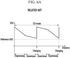
- FIGS. 5 , 6A , and 6B are exemplary graphs for describing a driving mode of a conventional plug-in hybrid electric vehicle according to the related art.
- the driving mode of the plug-in hybrid electric vehicle may include a charge depleting (CD) mode and a charge sustaining (CS) mode.
- CD charge depleting
- CS charge sustaining
- the driving mode of the plug-in hybrid electric vehicle is established as the CD mode and the plug-in hybrid electric vehicle is driven by electrical energy of the battery until a state of charge (SOC) of the battery reaches to a reference SOC.
- SOC state of charge
- an engine may start when a demand power of a driver is greater than a predetermined power.
- the driving mode of the plug-in hybrid electric vehicle is set to be the CS mode.
- the plug-in hybrid electric vehicle is driven so that the SOC of the battery corresponds to a target SOC.
- the setting of the CD mode is advantageous in energy efficiency independent of the traveling condition.
- the setting of the CD mode is not suitable in the energy efficiency under the specific traveling condition (e.g., expressway, uphill road, etc.).
- the present invention provides a method for controlling a plug-in hybrid electric vehicle according to claim 1, an apparatus for controlling a plug-in hybrid electric vehicle according to claim 12, and a non-transitory computer readable medium containing program instructions executed by a controller according to claim 16.
- FIG. 1 is a diagram of a plug-in hybrid electric vehicle according to an exemplary embodiment of the present invention.
- a plug-in hybrid electric vehicle 100 may include an engine 10, a motor 20, a battery 30, a data detector 40, a user interface unit 50, and a controller 60.
- the engine 10 may be configured to combust a fuel to generate power, and various engines such as a gasoline engine, a diesel engine, and an LPI engine may be used as the engine 10.
- torque generated from the engine 10 and/or the motor 20 may be selectively transmitted to an input shaft of a transmission, and torque output from an output shaft of the transmission may be transmitted to an axle via a differential gear apparatus.
- the axle may be configured to rotate a wheel to allow the torque generated from the engine 10 and/or the motor 20 to drive the plug-in hybrid electric vehicle 100.
- the battery 30 may be configured to supply electricity to the motor 20 and may be charged by an external power supply 200. Further, the battery 30 may be charged by braking and inertial energy recovered through electrical power generation of the motor 20 during braking of the vehicle or during driving the vehicle by inertia (i.e., regenerative braking mode).
- the data detector 40 may be configured to detect data used to operate the plug-in hybrid electric vehicle 100, and the data detected by the data detector 40 may be transmitted to the controller 60.
- the data detector 40 may include an accelerator pedal position sensor 41, a brake pedal position sensor 42, a vehicle speed sensor 43, an SOC sensor 44, and a gradient sensor 45.
- the accelerator pedal position sensor 41 may be configured to detect a position value of an accelerator pedal (e.g., an engagement degree or the amount of pressured exerted onto the accelerator pedal) and transmit a signal corresponding thereto to the controller 60. When the accelerator pedal is completely engaged, the position value of the accelerator pedal may be about 100%, and when the accelerator pedal is disengaged (e.g., no pressure is exerted onto the accelerator pedal), the position value of the accelerator pedal may be about 0%.
- the brake pedal position detector 42 may be configured to detect a position value of a brake pedal (e.g., an engagement degree or the amount of pressure exerted onto the brake pedal) and transmit a signal corresponding thereto to the controller 60.
- a position value of a brake pedal e.g., an engagement degree or the amount of pressure exerted onto the brake pedal
- the position value of the brake pedal may be about 100%
- the brake pedal is disengaged e.g. no pressure is exerted onto the brake pedal
- the vehicle speed sensor 43 may be configured to detect a vehicle speed and transmit a signal corresponding thereto to the controller 60.
- the SOC sensor 44 may be configured to detect a state of charge (SOC) of the battery 30 and transmit a signal corresponding thereto to the controller 60. Instead of directly detecting the SOC of the battery 30, a current and a voltage of the battery 30 may be measured, and the SOC of the battery 30 may be calculated from the measured current and voltage.
- SOC state of charge
- the gradient sensor 45 may be configured to detect gradient of a road on which the plug-in hybrid electric vehicle 100 is currently positioned (e.g., road on which the vehicle is being driven) and transmit a signal corresponding thereto to the controller 60.
- the user interface unit 50 may be configured to provide an interface for user (e.g., driver) selection (e.g., to an interface configured to receive user input) and transmit signals input based on a user manipulation to the controller 60.
- a navigation apparatus may be used as the user interface unit 50.
- the navigation apparatus may include an input and output unit for inputting and outputting information regarding route guidance, a current position detector configured to detect information regarding a current position of the plug-in hybrid electric vehicle 100, a memory in which map data required for route calculation and data required for guidance may be stored, an interface controller configured to perform a route search or a route guidance, and the like.
- the controller 60 may be implemented with one or more microprocessors executed by a predetermined program.
- the predetermined program may include a series of commands for performing each step included in a method for operating a plug-in hybrid electric vehicle 100 according to an exemplary embodiment of the present invention to be described below.
- the controller 60 may be configured to set a driving mode of the plug-in hybrid electric vehicle 100 to be a charge sustaining (CS) mode or a charge depleting (CD) mode based on the signals input from the data detector 40 and the user interface unit 50.
- the controller 60 may be configured to calculate a demand power of the driver based on the accelerator pedal position value and the vehicle speed and determine whether to start the engine 10 based on the demand power of the driver.
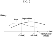
- FIG. 2 is a graph illustrating a starting of an engine of the plug-in hybrid electric vehicle 100 according to an exemplary embodiment of the present invention.
- the controller 60 when the driving mode of the plug-in hybrid electric vehicle 100 is set to be the CS mode and the demand power of the driver is greater than a first preset power P1, the controller 60 is configured to start the engine 10. In other words, when the energy efficiency at the time of using the engine 10 and the motor 20 is greater than that at the time of using the motor 20, the controller 60 is configured to start the engine 10.
- the controller 60 When the driving mode of the plug-in hybrid electric vehicle 100 is set to be the CD mode and the demand power of the driver is greater than a second preset power P2, the controller 60 is configured to start the engine 10. In other words, even though the energy efficiency while using the engine 10 and the motor 20 is greater than that when using the motor 20, when the demand power of the driver is equal to or less than the second preset power P2, the controller 60 is configured to use the electrical energy of the battery 30 charged by the external power supply 200 to drive the plug-in hybrid electric vehicle 100.
- the second preset power P2 may be set in consideration of the maximum power which may be output by the motor 20. According to the invention, the first predetermined power P1 is less than the second predetermined power P2.
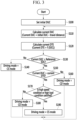
- FIG. 3 is a flow chart of the method for operating a plug-in hybrid electric vehicle according to an exemplary embodiment of the present invention
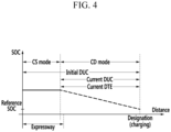
- FIG. 4 is a graph illustrating the method for operating a plug-in hybrid electric vehicle according to an exemplary embodiment of the present invention.
- the method for operating a plug-in hybrid electric vehicle begins with setting an initial distance until charge (DUC) (S100).
- DUC may be a remaining distance from the current position of the plug-in hybrid electric vehicle 100 to a charging station in which the battery 30 may be charged.
- the controller 60 is configured to set the initial DUC.
- the controller 60 may be configured to determine whether the battery 30 is charged by the external power supply 200.
- the controller 60 may be configured to display a message window requesting the input of the initial DUC through the user interface unit 50.
- the user interface unit 50 may be configured to transmit information regarding the initial DUC to the controller 60. Therefore, the charging intention of the driver may be clearly determined.
- the user interface unit 50 may be configured to transmit information regarding the destination to the controller 60.
- the controller 60 may, in response, be configured to set the distance from the current position of the plug-in hybrid electric vehicle 100 to the designation to be the initial DUC. Since the availability of battery charging at the destination may be unknown, the controller 60 may be configured to set the initial DUC using the destination when it does not receive the information regarding the initial DUC from the user interface unit 50.
- the controller 60 is then configured to calculate a current DUC by subtracting a travel distance of the plug-in hybrid electric vehicle from the initial DUC after the initial DUC is set (S110).
- the controller 60 may also be configured to update the DUC based on the traveling of the plug-in hybrid electric vehicle 100.
- the controller 60 is configured to calculate a current distance to empty (DTE) based on a current SOC of the battery 30 (S120).
- the DTE is a drivable distance (e.g., drivable distance until the SOC of the battery 30 reaches the reference SOC) using the electrical energy of the battery 30.
- the controller 60 may be configured to calculate the current DTE based on a function using the current SOC of the battery 30 as a variable.
- the controller 60 may be configured to calculate the current DTE using a map table in which the DTE that corresponds to the SOC of the battery 30 is stored.
- the controller 60 is configured to compare the current SOC with the reference SOC (S130).
- the reference SOC may be set to be a value determined by those skilled in the art, in consideration of the energy efficiency of the engine 10 and the energy efficiency of the motor 20.
- the controller 60 may be configured to set the driving mode of the plug-in hybrid electric vehicle 100 to be the CS mode (S140).
- the controller 60 is configured to compare the demand power of the driver with the first preset power P1 to determine whether to start the engine 10.
- the controller 60 when the current SOC is greater than the reference SOC, the controller 60 is configured to compare the current DUC with the current DTE (S150). In the step S150, when the current DUC is equal to or less than the current DTE, the controller 60 may be configured to set the driving mode of the plug-in hybrid electric vehicle 100 to be the CD mode (S160). In the CD mode, the controller 60 is configured to compare the demand power of the driver with the second preset power P2 to determine whether to start the engine 10.
- the controller 60 is configured to determine whether a high speed condition or a high load condition is satisfied (S170).
- the high speed condition or the high load condition may be determined based on a moving average value of the vehicle speed and a moving average value of the gradient of the road.
- the controller 60 may be configured to calculate the moving average value MAV k of the vehicle speed at a current timing (k timing) based on the latest n vehicle speeds V k to V k-n+1 and n weight values WV 1 to WV n .
- the moving average value MAV k of the vehicle speed may be calculated using the following Equation.
- V k-n+i may be a vehicle speed at timing k - n + 1
- WV i may be an i-th weight value
- a sum of the n weight values WV 1 to WV n is 1 and an i-th weight value may be equal to or less than an (i+1)-th weight value (i.e., WV i ⁇ WV i+1 ).
- the (i + 1)-th weight value may be set to be equal to or greater than the i-th weight value, and thus the latest vehicle speed has the greatest effect on the moving average value MAV k of the vehicle speed.
- the controller 60 may be configured to calculate the moving average value MAS k of the gradient of the road at the current timing (k timing) based on the latest m gradients S k to S k-m+1 of the road and m weight values WS 1 to WS m .
- the moving average value MAS k of the gradient of the road may be calculated using the following Equation.
- S k-m+i may be a gradient of a road at timing k - m + 1 and WS i may be an i-th weight value.
- a sum of the m weight values WS 1 to WS m is 1 and an i-th weight value may be equal to or less than an (i+1)-th weight value (i.e., WS i ⁇ WS i+1 ).
- the (i + 1)-th weight value may be set to be equal to or greater than the i-th weight value, and thus the latest gradient of the road has the greatest effect on the moving average value MAS k of the gradient of the road.
- the controller 60 may be configured to determine whether the high speed condition or the high load condition is satisfied based on the moving average value MAV k of the vehicle speed and the moving average value MAS k of the gradient of the road. In other words, the controller 60 may be configured to determine whether the plug-in hybrid electric vehicle 100 is driving on an expressway or a uphill road which is not congested (e.g., no traffic). In the step S170, when the high speed condition or the high load condition is not satisfied, the controller 60 may be configured to set the driving mode of the plug-in hybrid electric vehicle 100 to be the CD mode (S180). In particular, the controller 60 may be configured to compare the demand power of the driver with the second preset power P2 to determine whether to start the engine 10.
- the controller 60 is configured to set the driving mode of the plug-in hybrid electric vehicle 100 to be the CS mode (S190).
- the controller 60 is configured to compare the demand power of the driver with the first preset power P1 to determine whether to start the engine 10.
- the controller 60 may return to the step S110 and each step of the method for operating a plug-in hybrid electric vehicle according to the exemplary embodiment of the present invention may be repeated.
- the method for operating a plug-in hybrid electric vehicle may end when the driving of the plug-in hybrid electric vehicle stops or the initial DUC is reset.
- it may be possible to set the driving mode of plug-in hybrid electric vehicle 100 suitable for the current traveling condition. As a result, it may be possible to improve the energy efficiency of the plug-in hybrid electric vehicle 100.
Landscapes
- Engineering & Computer Science (AREA)
- Chemical & Material Sciences (AREA)
- Combustion & Propulsion (AREA)
- Transportation (AREA)
- Mechanical Engineering (AREA)
- Automation & Control Theory (AREA)
- Human Computer Interaction (AREA)
- Electric Propulsion And Braking For Vehicles (AREA)
- Hybrid Electric Vehicles (AREA)
Description
- The present invention relates to a plug-in hybrid electric vehicle, and more particularly, to a method and an apparatus for controlling a plug-in hybrid electric vehicle.
-
JP 2010 280250 A -
EP 1 975 028 A2 discloses a driving support apparatus and a driving support method for a hybrid vehicle. - As is generally known in the art, a hybrid electric vehicle (HEV) uses an internal combustion engine and a battery power supply together to drive the vehicle. In other words, the hybrid electric vehicle uses power of the internal combustion engine and power of the motor which are efficiently combined to drive the vehicle. Recently, a plug-in hybrid electric vehicle (PHEV) has been researched in which a battery chargeable by an external power supply is mounted.
-
FIGS. 5 ,6A , and6B are exemplary graphs for describing a driving mode of a conventional plug-in hybrid electric vehicle according to the related art. As illustrated inFIGS. 5 and6A-6B , the driving mode of the plug-in hybrid electric vehicle may include a charge depleting (CD) mode and a charge sustaining (CS) mode. - When the battery is charged by the external power supply, the driving mode of the plug-in hybrid electric vehicle is established as the CD mode and the plug-in hybrid electric vehicle is driven by electrical energy of the battery until a state of charge (SOC) of the battery reaches to a reference SOC. In particular, an engine may start when a demand power of a driver is greater than a predetermined power. When the SOC of the battery becomes the reference SOC, the driving mode of the plug-in hybrid electric vehicle is set to be the CS mode. Particularly, the plug-in hybrid electric vehicle is driven so that the SOC of the battery corresponds to a target SOC.
- When the SOC of the battery is maintained to be greater than the reference SOC and the battery may again be charged by the external power supply, the setting of the CD mode is advantageous in energy efficiency independent of the traveling condition. However, when the battery is again charged by the external power supply when the SOC of the battery is equal to or less than the reference SOC, even though the SOC of the battery is greater than the reference SOC, the setting of the CD mode is not suitable in the energy efficiency under the specific traveling condition (e.g., expressway, uphill road, etc.).
- The above information disclosed in this section is merely for enhancement of understanding of the background of the invention and therefore it may contain information that does not form the prior art that is already known in this country to a person of ordinary skill in the art.
- The present invention provides a method for controlling a plug-in hybrid electric vehicle according to claim 1, an apparatus for controlling a plug-in hybrid electric vehicle according to claim 12, and a non-transitory computer readable medium containing program instructions executed by a controller according to claim 16.
- The drawings are for reference in describing an exemplary embodiment of the present invention, so that it shall not be construed that the scope of the present invention is limited to the accompanying drawings.
-
FIG. 1 is a diagram of a plug-in hybrid electric vehicle according to an exemplary embodiment of the present invention; -
FIG. 2 is a graph illustrating a starting of an engine of the plug-in hybrid electric vehicle according to an exemplary embodiment of the present invention; -
FIG. 3 is a flow chart of a method for operating a plug-in hybrid electric vehicle according to an exemplary embodiment of the present invention; -
FIG. 4 is a graph illustrating the method for operating a plug-in hybrid electric vehicle according to an exemplary embodiment of the present invention; and -
FIGS. 5 ,6A , and6B are graphs illustrating a driving mode of a conventional plug-in hybrid electric vehicle according to the related art. -
- 10: Engine
- 20: Motor
- 30: Battery
- 40: Data detector
- 50: User interface unit
- 60: Controller
- 100: Plug-in hybrid electric vehicle
- 200: External power supply
- Hereinafter, the present invention will be described more fully hereinafter with reference to the accompanying drawings, in which exemplary embodiments of the invention are shown. However, the present invention is not limited to the exemplary embodiments set forth herein but may be modified in many different forms within the scope defined by the appended claims.
-
FIG. 1 is a diagram of a plug-in hybrid electric vehicle according to an exemplary embodiment of the present invention. As illustrated inFIG. 1 , a plug-in hybridelectric vehicle 100 according to an exemplary embodiment of the present invention may include anengine 10, amotor 20, abattery 30, adata detector 40, auser interface unit 50, and acontroller 60. - The
engine 10 may be configured to combust a fuel to generate power, and various engines such as a gasoline engine, a diesel engine, and an LPI engine may be used as theengine 10. In connection with torque transmission of the plug-in hybridelectric vehicle 100, torque generated from theengine 10 and/or themotor 20 may be selectively transmitted to an input shaft of a transmission, and torque output from an output shaft of the transmission may be transmitted to an axle via a differential gear apparatus. The axle may be configured to rotate a wheel to allow the torque generated from theengine 10 and/or themotor 20 to drive the plug-in hybridelectric vehicle 100. Thebattery 30 may be configured to supply electricity to themotor 20 and may be charged by anexternal power supply 200. Further, thebattery 30 may be charged by braking and inertial energy recovered through electrical power generation of themotor 20 during braking of the vehicle or during driving the vehicle by inertia (i.e., regenerative braking mode). - Further, the
data detector 40 may be configured to detect data used to operate the plug-in hybridelectric vehicle 100, and the data detected by thedata detector 40 may be transmitted to thecontroller 60. Thedata detector 40 may include an acceleratorpedal position sensor 41, a brakepedal position sensor 42, avehicle speed sensor 43, anSOC sensor 44, and agradient sensor 45. The acceleratorpedal position sensor 41 may be configured to detect a position value of an accelerator pedal (e.g., an engagement degree or the amount of pressured exerted onto the accelerator pedal) and transmit a signal corresponding thereto to thecontroller 60. When the accelerator pedal is completely engaged, the position value of the accelerator pedal may be about 100%, and when the accelerator pedal is disengaged (e.g., no pressure is exerted onto the accelerator pedal), the position value of the accelerator pedal may be about 0%. - Additionally, the brake
pedal position detector 42 may be configured to detect a position value of a brake pedal (e.g., an engagement degree or the amount of pressure exerted onto the brake pedal) and transmit a signal corresponding thereto to thecontroller 60. When the brake pedal is completely engaged, the position value of the brake pedal may be about 100%, and when the brake pedal is disengaged (e.g. no pressure is exerted onto the brake pedal), the position value of the brake pedal may be about 0%. - The
vehicle speed sensor 43 may be configured to detect a vehicle speed and transmit a signal corresponding thereto to thecontroller 60. TheSOC sensor 44 may be configured to detect a state of charge (SOC) of thebattery 30 and transmit a signal corresponding thereto to thecontroller 60. Instead of directly detecting the SOC of thebattery 30, a current and a voltage of thebattery 30 may be measured, and the SOC of thebattery 30 may be calculated from the measured current and voltage. - The
gradient sensor 45 may be configured to detect gradient of a road on which the plug-in hybridelectric vehicle 100 is currently positioned (e.g., road on which the vehicle is being driven) and transmit a signal corresponding thereto to thecontroller 60. Theuser interface unit 50 may be configured to provide an interface for user (e.g., driver) selection (e.g., to an interface configured to receive user input) and transmit signals input based on a user manipulation to thecontroller 60. Particularly, a navigation apparatus may be used as theuser interface unit 50. The navigation apparatus may include an input and output unit for inputting and outputting information regarding route guidance, a current position detector configured to detect information regarding a current position of the plug-in hybridelectric vehicle 100, a memory in which map data required for route calculation and data required for guidance may be stored, an interface controller configured to perform a route search or a route guidance, and the like. - The
controller 60 may be implemented with one or more microprocessors executed by a predetermined program. The predetermined program may include a series of commands for performing each step included in a method for operating a plug-in hybridelectric vehicle 100 according to an exemplary embodiment of the present invention to be described below. In particular, thecontroller 60 may be configured to set a driving mode of the plug-in hybridelectric vehicle 100 to be a charge sustaining (CS) mode or a charge depleting (CD) mode based on the signals input from thedata detector 40 and theuser interface unit 50. Thecontroller 60 may be configured to calculate a demand power of the driver based on the accelerator pedal position value and the vehicle speed and determine whether to start theengine 10 based on the demand power of the driver. -
FIG. 2 is a graph illustrating a starting of an engine of the plug-in hybridelectric vehicle 100 according to an exemplary embodiment of the present invention. Referring toFIG. 2 , when the driving mode of the plug-in hybridelectric vehicle 100 is set to be the CS mode and the demand power of the driver is greater than a first preset power P1, thecontroller 60 is configured to start theengine 10. In other words, when the energy efficiency at the time of using theengine 10 and themotor 20 is greater than that at the time of using themotor 20, thecontroller 60 is configured to start theengine 10. - When the driving mode of the plug-in hybrid
electric vehicle 100 is set to be the CD mode and the demand power of the driver is greater than a second preset power P2, thecontroller 60 is configured to start theengine 10. In other words, even though the energy efficiency while using theengine 10 and themotor 20 is greater than that when using themotor 20, when the demand power of the driver is equal to or less than the second preset power P2, thecontroller 60 is configured to use the electrical energy of thebattery 30 charged by theexternal power supply 200 to drive the plug-in hybridelectric vehicle 100. The second preset power P2 may be set in consideration of the maximum power which may be output by themotor 20. According to the invention, the first predetermined power P1 is less than the second predetermined power P2. - Hereinafter, the method for controlling a plug-in hybrid electric vehicle according to the exemplary embodiment of the present invention will be described in detail with reference to
FIGS. 1 to 4 .FIG. 3 is a flow chart of the method for operating a plug-in hybrid electric vehicle according to an exemplary embodiment of the present invention andFIG. 4 is a graph illustrating the method for operating a plug-in hybrid electric vehicle according to an exemplary embodiment of the present invention. - Referring to
FIGS. 1 to 4 , the method for operating a plug-in hybrid electric vehicle according to the exemplary embodiment of the present invention begins with setting an initial distance until charge (DUC) (S100). The DUC may be a remaining distance from the current position of the plug-in hybridelectric vehicle 100 to a charging station in which thebattery 30 may be charged. - The
controller 60 is configured to set the initial DUC. For example, thecontroller 60 may be configured to determine whether thebattery 30 is charged by theexternal power supply 200. When thebattery 30 is charged by theexternal power supply 200, thecontroller 60 may be configured to display a message window requesting the input of the initial DUC through theuser interface unit 50. When the user such as the driver inputs the initial DUC through theuser interface unit 50, theuser interface unit 50 may be configured to transmit information regarding the initial DUC to thecontroller 60. Therefore, the charging intention of the driver may be clearly determined. - Alternatively, when the driver inputs a destination through the
user interface unit 50, theuser interface unit 50 may be configured to transmit information regarding the destination to thecontroller 60. Thecontroller 60 may, in response, be configured to set the distance from the current position of the plug-in hybridelectric vehicle 100 to the designation to be the initial DUC. Since the availability of battery charging at the destination may be unknown, thecontroller 60 may be configured to set the initial DUC using the destination when it does not receive the information regarding the initial DUC from theuser interface unit 50. - The
controller 60 is then configured to calculate a current DUC by subtracting a travel distance of the plug-in hybrid electric vehicle from the initial DUC after the initial DUC is set (S110). Thecontroller 60 may also be configured to update the DUC based on the traveling of the plug-in hybridelectric vehicle 100. Additionally, thecontroller 60 is configured to calculate a current distance to empty (DTE) based on a current SOC of the battery 30 (S120). The DTE is a drivable distance (e.g., drivable distance until the SOC of thebattery 30 reaches the reference SOC) using the electrical energy of thebattery 30. Thecontroller 60 may be configured to calculate the current DTE based on a function using the current SOC of thebattery 30 as a variable. Alternatively, thecontroller 60 may be configured to calculate the current DTE using a map table in which the DTE that corresponds to the SOC of thebattery 30 is stored. - Further, the
controller 60 is configured to compare the current SOC with the reference SOC (S130). The reference SOC may be set to be a value determined by those skilled in the art, in consideration of the energy efficiency of theengine 10 and the energy efficiency of themotor 20. In the step S130, when the current SOC is equal to or less than the reference SOC, thecontroller 60 may be configured to set the driving mode of the plug-in hybridelectric vehicle 100 to be the CS mode (S140). In the CS mode, thecontroller 60 is configured to compare the demand power of the driver with the first preset power P1 to determine whether to start theengine 10. - In the step S130, when the current SOC is greater than the reference SOC, the
controller 60 is configured to compare the current DUC with the current DTE (S150). In the step S150, when the current DUC is equal to or less than the current DTE, thecontroller 60 may be configured to set the driving mode of the plug-in hybridelectric vehicle 100 to be the CD mode (S160). In the CD mode, thecontroller 60 is configured to compare the demand power of the driver with the second preset power P2 to determine whether to start theengine 10. - In the step S150, when the current DUC is greater than the current DTE, the
controller 60 is configured to determine whether a high speed condition or a high load condition is satisfied (S170). The high speed condition or the high load condition may be determined based on a moving average value of the vehicle speed and a moving average value of the gradient of the road. In the step S170, thecontroller 60 may be configured to calculate the moving average value MAVk of the vehicle speed at a current timing (k timing) based on the latest n vehicle speeds Vk to Vk-n+1 and n weight values WV1 to WVn. The moving average value MAVk of the vehicle speed may be calculated using the following Equation.
- A sum of the n weight values WV1 to WVn is 1 and an i-th weight value may be equal to or less than an (i+1)-th weight value (i.e., WVi ≤ WVi+1). The (i + 1)-th weight value may be set to be equal to or greater than the i-th weight value, and thus the latest vehicle speed has the greatest effect on the moving average value MAVk of the vehicle speed.
- In the step S170, the
controller 60 may be configured to calculate the moving average value MASk of the gradient of the road at the current timing (k timing) based on the latest m gradients Sk to Sk-m+1 of the road and m weight values WS1 to WSm. The moving average value MASk of the gradient of the road may be calculated using the following Equation.
- A sum of the m weight values WS1 to WSm is 1 and an i-th weight value may be equal to or less than an (i+1)-th weight value (i.e., WSi ≤ WSi+1). The (i + 1)-th weight value may be set to be equal to or greater than the i-th weight value, and thus the latest gradient of the road has the greatest effect on the moving average value MASk of the gradient of the road.
- The
controller 60 may be configured to determine whether the high speed condition or the high load condition is satisfied based on the moving average value MAVk of the vehicle speed and the moving average value MASk of the gradient of the road. In other words, thecontroller 60 may be configured to determine whether the plug-in hybridelectric vehicle 100 is driving on an expressway or a uphill road which is not congested (e.g., no traffic). In the step S170, when the high speed condition or the high load condition is not satisfied, thecontroller 60 may be configured to set the driving mode of the plug-in hybridelectric vehicle 100 to be the CD mode (S180). In particular, thecontroller 60 may be configured to compare the demand power of the driver with the second preset power P2 to determine whether to start theengine 10. - In the step S170, when the high speed condition or the high load condition is satisfied, the
controller 60 is configured to set the driving mode of the plug-in hybridelectric vehicle 100 to be the CS mode (S190). In the CS mode, thecontroller 60 is configured to compare the demand power of the driver with the first preset power P1 to determine whether to start theengine 10. After the driving mode of the plug-in hybridelectric vehicle 100 is set, thecontroller 60 may return to the step S110 and each step of the method for operating a plug-in hybrid electric vehicle according to the exemplary embodiment of the present invention may be repeated. - Meanwhile, the method for operating a plug-in hybrid electric vehicle according to the exemplary embodiment of the present invention may end when the driving of the plug-in hybrid electric vehicle stops or the initial DUC is reset. As described above, according to an exemplary embodiment of the present invention, it may be possible to set the driving mode of plug-in hybrid
electric vehicle 100 suitable for the current traveling condition. As a result, it may be possible to improve the energy efficiency of the plug-in hybridelectric vehicle 100. - While this invention has been described in connection with what is presently considered to be exemplary embodiments, it is to be understood that the invention is not limited to the disclosed exemplary embodiments, but, on the contrary, is intended to cover various modifications included within the scope of the appended claims.
Claims (18)
- A method for controlling a plug-in hybrid electric vehicle (100), comprising:setting, by a controller (60), an initial distance until charge (DUC);calculating, by the controller (60), a current DUC by subtracting a travel distance of the plug-in hybrid electric vehicle (100) from the initial DUC after the initial DUC is set;calculating, by the controller (60), a current distance to empty (DTE) based on a current state of charge (SOC) of a battery (30);comparing, by the controller (60), the current SOC of the battery (30) with a reference SOC;comparing, by the controller (60), the current DUC with the current DTE when the current SOC is greater than the reference SOC;determining, by the controller (60), whether a high speed condition or a high load condition is satisfied when the current DUC is greater than the current DTE;setting, by the controller (60), a driving mode of the plug-in hybrid electric vehicle (100) to be a charge sustaining (CS) mode when the high speed condition or the high load condition is satisfied; characterized in that the method further comprises the following steps:comparing, by the controller (60), demand power of a driver with a first predetermined power when the driving mode of the plug-in hybrid electric vehicle (100) is set to be the CS mode;starting, by the controller (60), an engine (10) when the demand power of the driver is greater than the first predetermined power; andcomparing, by the controller (60), the demand power of the driver with a second predetermined power when the driving mode of the plug-in hybrid electric vehicle (100) is set to be a charge depleting (CD) mode; andstarting, by the controller (60), the engine (10) when the demand power of the driver is greater than the second predetermined power,wherein the first predetermined power is less than the second predetermined power.
- The method of claim 1, wherein the setting of the initial DUC includes:determining, by the controller (60), whether the battery (30) is charged by an external power supply (200);displaying, by the controller (60), a message window requesting an input of the initial DUC through a user interface unit (50) when the battery (30) is charged by the external power supply (200); andreceiving, by the controller (60), information regarding the initial DUC from the user interface unit (50).
- The method of claim 1, wherein the setting of the initial DUC includes:receiving, by the controller (60), information regarding a designation through the user interface unit (50); andsetting, by the controller (60), a distance from a current position of the plug-in hybrid electric vehicle (100) to a destination to be the initial DUC.
- The method of claim 1, further comprising:
setting, by the controller (60), the driving mode of the plug-in hybrid electric vehicle (100) to be a CS mode when the current SOC of the battery (30) is less than or equal to the reference SOC. - The method of claim 1, further comprising:
setting, by the controller (60), the driving mode of the plug-in hybrid electric vehicle (100) to be a charge depleting (CD) mode when the current DUC is less than or equal to the current DTE. - The method of claim 1, further comprising:
setting, by the controller (60), a driving mode of the plug-in hybrid electric vehicle (100) to be a charge depleting (CD) mode when the high speed condition or the high load condition is not satisfied. - The method of claim 1, wherein whether the high speed condition or the high load condition is satisfied is determined based on a moving average value of a vehicle speed and a moving average value of a gradient of a road.
- The method of claim 7, wherein the moving average value MAVk of the vehicle speed is calculated using the following equation:

- The method of claim 8, wherein the n weight values satisfy relation of WVi ≤ WVi+1.
- The method of claim 7, wherein the moving average value MASk of the gradient of the road is calculated using the following equation:

- The method of claim 10, wherein the m weight values satisfy relation of WSi ≤ WSi+1.
- An apparatus for controlling a plug-in hybrid electric vehicle (100), comprising:a data detector (40) configured to detect data for operating the plug-in hybrid electric vehicle (100);a user interface unit (50) configured to provide an interface to receive user input; anda controller (60) configured to operate the plug-in hybrid electric vehicle (100) based on signals input from the data detector (40) and the user interface unit (50) according to the method of claim 1.
- The apparatus of claim 12, wherein in the setting of the initial DUC the controller (60) is further configured to:determine whether the battery (30) is charged by an external power supply (200);display a message window requesting an input of the initial DUC through a user interface unit (50) when the battery (30) is charged by the external power supply (200); andreceive information regarding the initial DUC from the user interface unit (50).
- The apparatus of claim 12, wherein the controller (60) is further configured to set the driving mode of the plug-in hybrid electric vehicle (100) to be a CS mode when the current SOC of the battery (30) is less than or equal to the reference SOC.
- The apparatus of claim 12, wherein the controller (60) is further configured to set the driving mode of the plug-in hybrid electric vehicle (100) to be a charge depleting (CD) mode when the current DUC is less than or equal to the current DTE.
- A non-transitory computer readable medium containing program instructions to execute the method according to claim 1 when executed on an apparatus according to claim 12.
- The non-transitory computer readable medium of claim 16, further comprising program instructions that set the driving mode of the plug-in hybrid electric vehicle (100) to be a CS mode when the current SOC of the battery (30) is less than or equal to the reference SOC.
- The non-transitory computer readable medium of claim 16, further comprising program instructions that set the driving mode of the plug-in hybrid electric vehicle (100) to be a charge depleting (CD) mode when the current DUC is less than or equal to the current DTE.
Applications Claiming Priority (1)
| Application Number | Priority Date | Filing Date | Title |
|---|---|---|---|
| KR1020150079293A KR101655216B1 (en) | 2015-06-04 | 2015-06-04 | Method and apparatus for controlling plug-in hybrid electric vehicle |
Publications (2)
| Publication Number | Publication Date |
|---|---|
| EP3100924A1 EP3100924A1 (en) | 2016-12-07 |
| EP3100924B1 true EP3100924B1 (en) | 2024-03-27 |
Family
ID=54541948
Family Applications (1)
| Application Number | Title | Priority Date | Filing Date |
|---|---|---|---|
| EP15191961.0A Active EP3100924B1 (en) | 2015-06-04 | 2015-10-28 | Method and apparatus for controlling plug-in hybrid electric vehicle, as well as computer-readable medium |
Country Status (4)
| Country | Link |
|---|---|
| US (1) | US9527502B1 (en) |
| EP (1) | EP3100924B1 (en) |
| KR (1) | KR101655216B1 (en) |
| CN (1) | CN106240561B (en) |
Families Citing this family (10)
| Publication number | Priority date | Publication date | Assignee | Title |
|---|---|---|---|---|
| US10351009B2 (en) * | 2015-07-31 | 2019-07-16 | Ford Global Technologies, Llc | Electric vehicle display systems |
| JP6489098B2 (en) * | 2016-11-02 | 2019-03-27 | トヨタ自動車株式会社 | Vehicle control device |
| JP2018090194A (en) * | 2016-12-07 | 2018-06-14 | トヨタ自動車株式会社 | Hybrid vehicle |
| KR102343956B1 (en) * | 2017-07-31 | 2021-12-27 | 현대자동차주식회사 | Hybrid vehicle and method of changing operation mode for the same |
| KR102410942B1 (en) * | 2017-11-01 | 2022-06-20 | 현대자동차주식회사 | Hybrid vehicle and method of changing operation mode for the same |
| KR102444667B1 (en) * | 2017-12-28 | 2022-09-19 | 현대자동차주식회사 | Hybrid vehicle and driving mode control method therefor |
| US12325322B2 (en) * | 2018-10-09 | 2025-06-10 | Regents Of The University Of Minnesota | Physical model-guided machine learning framework for energy management of vehicles |
| DE102019119969A1 (en) * | 2019-07-24 | 2021-01-28 | Volkswagen Aktiengesellschaft | Procedure for displaying a warning message |
| CN112660103B (en) * | 2020-12-31 | 2023-04-07 | 重庆金康赛力斯新能源汽车设计院有限公司 | Vehicle control mode determination method and device and whole vehicle control system |
| CN117818363A (en) * | 2024-01-19 | 2024-04-05 | 广州汽车集团股份有限公司 | Vehicle charging control method and device, electronic device, and storage medium |
Family Cites Families (23)
| Publication number | Priority date | Publication date | Assignee | Title |
|---|---|---|---|---|
| JP4506721B2 (en) * | 2006-05-18 | 2010-07-21 | 日産自動車株式会社 | Hybrid vehicle control device and hybrid vehicle control method. |
| JP2008087516A (en) | 2006-09-29 | 2008-04-17 | Toyota Motor Corp | Hybrid vehicle and drive control method of the same |
| JP4438812B2 (en) | 2007-03-27 | 2010-03-24 | アイシン・エィ・ダブリュ株式会社 | Hybrid travel assist method and hybrid travel assist device |
| KR100867795B1 (en) | 2007-07-13 | 2008-11-10 | 현대자동차주식회사 | DC / DC converter operation control method of hybrid vehicle |
| JP5257923B2 (en) * | 2008-01-31 | 2013-08-07 | 株式会社アドヴィックス | Vehicle motion control device |
| JP4692646B2 (en) * | 2009-02-04 | 2011-06-01 | 株式会社デンソー | Power source control device |
| JP2010280250A (en) | 2009-06-02 | 2010-12-16 | Denso Corp | Power source control device |
| JP5499538B2 (en) * | 2009-07-10 | 2014-05-21 | 日産自動車株式会社 | Control device for hybrid vehicle |
| JP5691145B2 (en) | 2009-08-10 | 2015-04-01 | ソニー株式会社 | Vehicle route determination method and navigation apparatus |
| JP5223822B2 (en) * | 2009-09-11 | 2013-06-26 | トヨタ自動車株式会社 | Display device and hybrid vehicle including the same |
| US8359133B2 (en) * | 2010-02-19 | 2013-01-22 | Ford Global Technologies, Llc | Engine power elevation and active battery charge energy management strategies for plug-in hybrid electric vehicles |
| US8543272B2 (en) | 2010-08-05 | 2013-09-24 | Ford Global Technologies, Llc | Distance oriented energy management strategy for a hybrid electric vehicle |
| US9199616B2 (en) | 2010-12-20 | 2015-12-01 | Caterpillar Inc. | System and method for determining a ground speed of a machine |
| US10065628B2 (en) * | 2011-05-09 | 2018-09-04 | Ford Global Technologies, Llc | Location enhanced distance until charge (DUC) estimation for a plug-in hybrid electric vehicle (PHEV) |
| KR101180801B1 (en) | 2011-06-30 | 2012-09-10 | 현대자동차주식회사 | Method for increasing mileage of electric vehicle using auxiliary battery |
| WO2013009711A1 (en) * | 2011-07-08 | 2013-01-17 | Timler John P | Insulator based upon one or more dielectric structures |
| JP5836068B2 (en) | 2011-10-31 | 2015-12-24 | 日立オートモティブシステムズ株式会社 | Vehicle power supply device, electric vehicle |
| US9020743B2 (en) * | 2012-02-20 | 2015-04-28 | Ford Global Technologies, Llc | Methods and apparatus for predicting a driver destination |
| US9050969B2 (en) * | 2012-12-11 | 2015-06-09 | Ford Global Technologies, Llc | Trip oriented energy management control |
| KR101509693B1 (en) * | 2013-06-12 | 2015-04-16 | 현대자동차 주식회사 | System and method of determining short term driving tendency of driver |
| US9378595B2 (en) * | 2014-08-29 | 2016-06-28 | Ford Global Technologies, Llc | Instantaneous status to target gauge for vehicle application |
| US10118499B2 (en) * | 2014-09-23 | 2018-11-06 | Ford Global Technologies, Llc | Distance until charge prediction for vehicles |
| US9676283B2 (en) * | 2014-11-07 | 2017-06-13 | Ford Global Technologies, Llc | Method and system for pre-cooling traction battery in anticipation of recharging at charging station |
-
2015
- 2015-06-04 KR KR1020150079293A patent/KR101655216B1/en active Active
- 2015-10-23 US US14/920,934 patent/US9527502B1/en active Active
- 2015-10-28 EP EP15191961.0A patent/EP3100924B1/en active Active
- 2015-11-13 CN CN201510783364.6A patent/CN106240561B/en active Active
Also Published As
| Publication number | Publication date |
|---|---|
| CN106240561A (en) | 2016-12-21 |
| US20160355172A1 (en) | 2016-12-08 |
| KR101655216B1 (en) | 2016-09-07 |
| EP3100924A1 (en) | 2016-12-07 |
| CN106240561B (en) | 2022-07-08 |
| US9527502B1 (en) | 2016-12-27 |
Similar Documents
| Publication | Publication Date | Title |
|---|---|---|
| US9527502B1 (en) | Method and apparatus for controlling plug-in hybrid electric vehicle | |
| US8565952B2 (en) | Forward-looking hybrid vehicle control strategy | |
| KR101836250B1 (en) | Method and apparatus of controlling output voltage of dc converter for vehicle including driving motor | |
| JP2010000884A (en) | Control device for hybrid vehicle | |
| CN103764465A (en) | Vehicle state display device in hybrid vehicle | |
| CN106627561B (en) | The method and apparatus that energy storage device on vehicle is recharged | |
| EP3225491B1 (en) | Hybrid vehicle | |
| JP2020072581A (en) | Movable distance calculator | |
| US9856815B2 (en) | Engine control device and method of hybrid vehicle | |
| US10836276B2 (en) | Display device | |
| JP2016193686A (en) | Control device for hybrid vehicle | |
| WO2014167413A1 (en) | Hybrid vehicle | |
| JP7010043B2 (en) | Hybrid car | |
| EP3495216A1 (en) | Hybrid vehicle and controller for hybrid vehicle | |
| CN114643900A (en) | System and method for quantifying battery usage | |
| JP6662003B2 (en) | Control device for hybrid vehicle | |
| JP5256891B2 (en) | Charge control device | |
| US20160257291A1 (en) | Method and apparatus for generating torque command | |
| JP7010038B2 (en) | Hybrid car | |
| JP2021158778A (en) | Electric vehicle | |
| US11305770B2 (en) | Vehicle having controllable target driving force | |
| CN107757627B (en) | Vehicle control device and information providing method | |
| JP6720654B2 (en) | Clutch durability determination system, vehicle and clutch durability determination method | |
| US20250319759A1 (en) | Techniques for real-time energy consumption optimization in hybrid electric vehicles | |
| KR20120085961A (en) | Operating system and method for operating hybrid electric vehicle |
Legal Events
| Date | Code | Title | Description |
|---|---|---|---|
| PUAI | Public reference made under article 153(3) epc to a published international application that has entered the european phase |
Free format text: ORIGINAL CODE: 0009012 |
|
| STAA | Information on the status of an ep patent application or granted ep patent |
Free format text: STATUS: THE APPLICATION HAS BEEN PUBLISHED |
|
| AK | Designated contracting states |
Kind code of ref document: A1 Designated state(s): AL AT BE BG CH CY CZ DE DK EE ES FI FR GB GR HR HU IE IS IT LI LT LU LV MC MK MT NL NO PL PT RO RS SE SI SK SM TR |
|
| AX | Request for extension of the european patent |
Extension state: BA ME |
|
| STAA | Information on the status of an ep patent application or granted ep patent |
Free format text: STATUS: REQUEST FOR EXAMINATION WAS MADE |
|
| 17P | Request for examination filed |
Effective date: 20170607 |
|
| RBV | Designated contracting states (corrected) |
Designated state(s): AL AT BE BG CH CY CZ DE DK EE ES FI FR GB GR HR HU IE IS IT LI LT LU LV MC MK MT NL NO PL PT RO RS SE SI SK SM TR |
|
| STAA | Information on the status of an ep patent application or granted ep patent |
Free format text: STATUS: EXAMINATION IS IN PROGRESS |
|
| 17Q | First examination report despatched |
Effective date: 20180508 |
|
| RAP3 | Party data changed (applicant data changed or rights of an application transferred) |
Owner name: HYUNDAI MOTOR COMPANY Owner name: KIA CORPORATION |
|
| P01 | Opt-out of the competence of the unified patent court (upc) registered |
Effective date: 20230526 |
|
| REG | Reference to a national code |
Ref country code: DE Ref legal event code: R079 Free format text: PREVIOUS MAIN CLASS: B60W0020200000 Ipc: B60W0020120000 Ref country code: DE Ref legal event code: R079 Ref document number: 602015088054 Country of ref document: DE Free format text: PREVIOUS MAIN CLASS: B60W0020200000 Ipc: B60W0020120000 |
|
| GRAP | Despatch of communication of intention to grant a patent |
Free format text: ORIGINAL CODE: EPIDOSNIGR1 |
|
| STAA | Information on the status of an ep patent application or granted ep patent |
Free format text: STATUS: GRANT OF PATENT IS INTENDED |
|
| RIC1 | Information provided on ipc code assigned before grant |
Ipc: B60W 20/12 20160101AFI20231122BHEP |
|
| INTG | Intention to grant announced |
Effective date: 20231220 |
|
| GRAS | Grant fee paid |
Free format text: ORIGINAL CODE: EPIDOSNIGR3 |
|
| GRAA | (expected) grant |
Free format text: ORIGINAL CODE: 0009210 |
|
| STAA | Information on the status of an ep patent application or granted ep patent |
Free format text: STATUS: THE PATENT HAS BEEN GRANTED |
|
| AK | Designated contracting states |
Kind code of ref document: B1 Designated state(s): AL AT BE BG CH CY CZ DE DK EE ES FI FR GB GR HR HU IE IS IT LI LT LU LV MC MK MT NL NO PL PT RO RS SE SI SK SM TR |
|
| REG | Reference to a national code |
Ref country code: GB Ref legal event code: FG4D |
|
| REG | Reference to a national code |
Ref country code: CH Ref legal event code: EP |
|
| REG | Reference to a national code |
Ref country code: DE Ref legal event code: R096 Ref document number: 602015088054 Country of ref document: DE |
|
| REG | Reference to a national code |
Ref country code: IE Ref legal event code: FG4D |
|
| PG25 | Lapsed in a contracting state [announced via postgrant information from national office to epo] |
Ref country code: LT Free format text: LAPSE BECAUSE OF FAILURE TO SUBMIT A TRANSLATION OF THE DESCRIPTION OR TO PAY THE FEE WITHIN THE PRESCRIBED TIME-LIMIT Effective date: 20240327 |
|
| REG | Reference to a national code |
Ref country code: LT Ref legal event code: MG9D |
|
| PG25 | Lapsed in a contracting state [announced via postgrant information from national office to epo] |
Ref country code: GR Free format text: LAPSE BECAUSE OF FAILURE TO SUBMIT A TRANSLATION OF THE DESCRIPTION OR TO PAY THE FEE WITHIN THE PRESCRIBED TIME-LIMIT Effective date: 20240628 |
|
| PG25 | Lapsed in a contracting state [announced via postgrant information from national office to epo] |
Ref country code: RS Free format text: LAPSE BECAUSE OF FAILURE TO SUBMIT A TRANSLATION OF THE DESCRIPTION OR TO PAY THE FEE WITHIN THE PRESCRIBED TIME-LIMIT Effective date: 20240627 Ref country code: HR Free format text: LAPSE BECAUSE OF FAILURE TO SUBMIT A TRANSLATION OF THE DESCRIPTION OR TO PAY THE FEE WITHIN THE PRESCRIBED TIME-LIMIT Effective date: 20240327 |
|
| PG25 | Lapsed in a contracting state [announced via postgrant information from national office to epo] |
Ref country code: RS Free format text: LAPSE BECAUSE OF FAILURE TO SUBMIT A TRANSLATION OF THE DESCRIPTION OR TO PAY THE FEE WITHIN THE PRESCRIBED TIME-LIMIT Effective date: 20240627 Ref country code: NO Free format text: LAPSE BECAUSE OF FAILURE TO SUBMIT A TRANSLATION OF THE DESCRIPTION OR TO PAY THE FEE WITHIN THE PRESCRIBED TIME-LIMIT Effective date: 20240627 Ref country code: LT Free format text: LAPSE BECAUSE OF FAILURE TO SUBMIT A TRANSLATION OF THE DESCRIPTION OR TO PAY THE FEE WITHIN THE PRESCRIBED TIME-LIMIT Effective date: 20240327 Ref country code: HR Free format text: LAPSE BECAUSE OF FAILURE TO SUBMIT A TRANSLATION OF THE DESCRIPTION OR TO PAY THE FEE WITHIN THE PRESCRIBED TIME-LIMIT Effective date: 20240327 Ref country code: GR Free format text: LAPSE BECAUSE OF FAILURE TO SUBMIT A TRANSLATION OF THE DESCRIPTION OR TO PAY THE FEE WITHIN THE PRESCRIBED TIME-LIMIT Effective date: 20240628 Ref country code: FI Free format text: LAPSE BECAUSE OF FAILURE TO SUBMIT A TRANSLATION OF THE DESCRIPTION OR TO PAY THE FEE WITHIN THE PRESCRIBED TIME-LIMIT Effective date: 20240327 Ref country code: BG Free format text: LAPSE BECAUSE OF FAILURE TO SUBMIT A TRANSLATION OF THE DESCRIPTION OR TO PAY THE FEE WITHIN THE PRESCRIBED TIME-LIMIT Effective date: 20240327 |
|
| REG | Reference to a national code |
Ref country code: NL Ref legal event code: MP Effective date: 20240327 |
|
| PG25 | Lapsed in a contracting state [announced via postgrant information from national office to epo] |
Ref country code: SE Free format text: LAPSE BECAUSE OF FAILURE TO SUBMIT A TRANSLATION OF THE DESCRIPTION OR TO PAY THE FEE WITHIN THE PRESCRIBED TIME-LIMIT Effective date: 20240327 Ref country code: LV Free format text: LAPSE BECAUSE OF FAILURE TO SUBMIT A TRANSLATION OF THE DESCRIPTION OR TO PAY THE FEE WITHIN THE PRESCRIBED TIME-LIMIT Effective date: 20240327 |
|
| PG25 | Lapsed in a contracting state [announced via postgrant information from national office to epo] |
Ref country code: NL Free format text: LAPSE BECAUSE OF FAILURE TO SUBMIT A TRANSLATION OF THE DESCRIPTION OR TO PAY THE FEE WITHIN THE PRESCRIBED TIME-LIMIT Effective date: 20240327 |
|
| REG | Reference to a national code |
Ref country code: AT Ref legal event code: MK05 Ref document number: 1669638 Country of ref document: AT Kind code of ref document: T Effective date: 20240327 |
|
| PG25 | Lapsed in a contracting state [announced via postgrant information from national office to epo] |
Ref country code: NL Free format text: LAPSE BECAUSE OF FAILURE TO SUBMIT A TRANSLATION OF THE DESCRIPTION OR TO PAY THE FEE WITHIN THE PRESCRIBED TIME-LIMIT Effective date: 20240327 |
|
| PG25 | Lapsed in a contracting state [announced via postgrant information from national office to epo] |
Ref country code: IS Free format text: LAPSE BECAUSE OF FAILURE TO SUBMIT A TRANSLATION OF THE DESCRIPTION OR TO PAY THE FEE WITHIN THE PRESCRIBED TIME-LIMIT Effective date: 20240727 |
|
| PG25 | Lapsed in a contracting state [announced via postgrant information from national office to epo] |
Ref country code: SM Free format text: LAPSE BECAUSE OF FAILURE TO SUBMIT A TRANSLATION OF THE DESCRIPTION OR TO PAY THE FEE WITHIN THE PRESCRIBED TIME-LIMIT Effective date: 20240327 Ref country code: PT Free format text: LAPSE BECAUSE OF FAILURE TO SUBMIT A TRANSLATION OF THE DESCRIPTION OR TO PAY THE FEE WITHIN THE PRESCRIBED TIME-LIMIT Effective date: 20240729 |
|
| PG25 | Lapsed in a contracting state [announced via postgrant information from national office to epo] |
Ref country code: ES Free format text: LAPSE BECAUSE OF FAILURE TO SUBMIT A TRANSLATION OF THE DESCRIPTION OR TO PAY THE FEE WITHIN THE PRESCRIBED TIME-LIMIT Effective date: 20240327 |
|
| PG25 | Lapsed in a contracting state [announced via postgrant information from national office to epo] |
Ref country code: EE Free format text: LAPSE BECAUSE OF FAILURE TO SUBMIT A TRANSLATION OF THE DESCRIPTION OR TO PAY THE FEE WITHIN THE PRESCRIBED TIME-LIMIT Effective date: 20240327 Ref country code: CZ Free format text: LAPSE BECAUSE OF FAILURE TO SUBMIT A TRANSLATION OF THE DESCRIPTION OR TO PAY THE FEE WITHIN THE PRESCRIBED TIME-LIMIT Effective date: 20240327 |
|
| PG25 | Lapsed in a contracting state [announced via postgrant information from national office to epo] |
Ref country code: AT Free format text: LAPSE BECAUSE OF FAILURE TO SUBMIT A TRANSLATION OF THE DESCRIPTION OR TO PAY THE FEE WITHIN THE PRESCRIBED TIME-LIMIT Effective date: 20240327 |
|
| PG25 | Lapsed in a contracting state [announced via postgrant information from national office to epo] |
Ref country code: PL Free format text: LAPSE BECAUSE OF FAILURE TO SUBMIT A TRANSLATION OF THE DESCRIPTION OR TO PAY THE FEE WITHIN THE PRESCRIBED TIME-LIMIT Effective date: 20240327 |
|
| PG25 | Lapsed in a contracting state [announced via postgrant information from national office to epo] |
Ref country code: SK Free format text: LAPSE BECAUSE OF FAILURE TO SUBMIT A TRANSLATION OF THE DESCRIPTION OR TO PAY THE FEE WITHIN THE PRESCRIBED TIME-LIMIT Effective date: 20240327 |
|
| PG25 | Lapsed in a contracting state [announced via postgrant information from national office to epo] |
Ref country code: SM Free format text: LAPSE BECAUSE OF FAILURE TO SUBMIT A TRANSLATION OF THE DESCRIPTION OR TO PAY THE FEE WITHIN THE PRESCRIBED TIME-LIMIT Effective date: 20240327 Ref country code: SK Free format text: LAPSE BECAUSE OF FAILURE TO SUBMIT A TRANSLATION OF THE DESCRIPTION OR TO PAY THE FEE WITHIN THE PRESCRIBED TIME-LIMIT Effective date: 20240327 Ref country code: RO Free format text: LAPSE BECAUSE OF FAILURE TO SUBMIT A TRANSLATION OF THE DESCRIPTION OR TO PAY THE FEE WITHIN THE PRESCRIBED TIME-LIMIT Effective date: 20240327 Ref country code: PT Free format text: LAPSE BECAUSE OF FAILURE TO SUBMIT A TRANSLATION OF THE DESCRIPTION OR TO PAY THE FEE WITHIN THE PRESCRIBED TIME-LIMIT Effective date: 20240729 Ref country code: PL Free format text: LAPSE BECAUSE OF FAILURE TO SUBMIT A TRANSLATION OF THE DESCRIPTION OR TO PAY THE FEE WITHIN THE PRESCRIBED TIME-LIMIT Effective date: 20240327 Ref country code: IS Free format text: LAPSE BECAUSE OF FAILURE TO SUBMIT A TRANSLATION OF THE DESCRIPTION OR TO PAY THE FEE WITHIN THE PRESCRIBED TIME-LIMIT Effective date: 20240727 Ref country code: ES Free format text: LAPSE BECAUSE OF FAILURE TO SUBMIT A TRANSLATION OF THE DESCRIPTION OR TO PAY THE FEE WITHIN THE PRESCRIBED TIME-LIMIT Effective date: 20240327 Ref country code: EE Free format text: LAPSE BECAUSE OF FAILURE TO SUBMIT A TRANSLATION OF THE DESCRIPTION OR TO PAY THE FEE WITHIN THE PRESCRIBED TIME-LIMIT Effective date: 20240327 Ref country code: CZ Free format text: LAPSE BECAUSE OF FAILURE TO SUBMIT A TRANSLATION OF THE DESCRIPTION OR TO PAY THE FEE WITHIN THE PRESCRIBED TIME-LIMIT Effective date: 20240327 Ref country code: AT Free format text: LAPSE BECAUSE OF FAILURE TO SUBMIT A TRANSLATION OF THE DESCRIPTION OR TO PAY THE FEE WITHIN THE PRESCRIBED TIME-LIMIT Effective date: 20240327 |
|
| REG | Reference to a national code |
Ref country code: DE Ref legal event code: R097 Ref document number: 602015088054 Country of ref document: DE |
|
| PG25 | Lapsed in a contracting state [announced via postgrant information from national office to epo] |
Ref country code: DK Free format text: LAPSE BECAUSE OF FAILURE TO SUBMIT A TRANSLATION OF THE DESCRIPTION OR TO PAY THE FEE WITHIN THE PRESCRIBED TIME-LIMIT Effective date: 20240327 |
|
| PG25 | Lapsed in a contracting state [announced via postgrant information from national office to epo] |
Ref country code: DK Free format text: LAPSE BECAUSE OF FAILURE TO SUBMIT A TRANSLATION OF THE DESCRIPTION OR TO PAY THE FEE WITHIN THE PRESCRIBED TIME-LIMIT Effective date: 20240327 |
|
| PLBE | No opposition filed within time limit |
Free format text: ORIGINAL CODE: 0009261 |
|
| STAA | Information on the status of an ep patent application or granted ep patent |
Free format text: STATUS: NO OPPOSITION FILED WITHIN TIME LIMIT |
|
| 26N | No opposition filed |
Effective date: 20250103 |
|
| PG25 | Lapsed in a contracting state [announced via postgrant information from national office to epo] |
Ref country code: SI Free format text: LAPSE BECAUSE OF FAILURE TO SUBMIT A TRANSLATION OF THE DESCRIPTION OR TO PAY THE FEE WITHIN THE PRESCRIBED TIME-LIMIT Effective date: 20240327 |
|
| REG | Reference to a national code |
Ref country code: CH Ref legal event code: PL |
|
| GBPC | Gb: european patent ceased through non-payment of renewal fee |
Effective date: 20241028 |
|
| PG25 | Lapsed in a contracting state [announced via postgrant information from national office to epo] |
Ref country code: MC Free format text: LAPSE BECAUSE OF FAILURE TO SUBMIT A TRANSLATION OF THE DESCRIPTION OR TO PAY THE FEE WITHIN THE PRESCRIBED TIME-LIMIT Effective date: 20240327 |
|
| PG25 | Lapsed in a contracting state [announced via postgrant information from national office to epo] |
Ref country code: GB Free format text: LAPSE BECAUSE OF NON-PAYMENT OF DUE FEES Effective date: 20241028 |
|
| PG25 | Lapsed in a contracting state [announced via postgrant information from national office to epo] |
Ref country code: BE Free format text: LAPSE BECAUSE OF NON-PAYMENT OF DUE FEES Effective date: 20241031 Ref country code: LU Free format text: LAPSE BECAUSE OF NON-PAYMENT OF DUE FEES Effective date: 20241028 |
|
| PG25 | Lapsed in a contracting state [announced via postgrant information from national office to epo] |
Ref country code: CH Free format text: LAPSE BECAUSE OF NON-PAYMENT OF DUE FEES Effective date: 20241031 |
|
| REG | Reference to a national code |
Ref country code: BE Ref legal event code: MM Effective date: 20241031 |
|
| PGFP | Annual fee paid to national office [announced via postgrant information from national office to epo] |
Ref country code: IT Payment date: 20250924 Year of fee payment: 11 |
|
| PGFP | Annual fee paid to national office [announced via postgrant information from national office to epo] |
Ref country code: FR Payment date: 20250925 Year of fee payment: 11 |
|
| PG25 | Lapsed in a contracting state [announced via postgrant information from national office to epo] |
Ref country code: IE Free format text: LAPSE BECAUSE OF NON-PAYMENT OF DUE FEES Effective date: 20241028 |
|
| PGFP | Annual fee paid to national office [announced via postgrant information from national office to epo] |
Ref country code: DE Payment date: 20250922 Year of fee payment: 11 |
|
| PG25 | Lapsed in a contracting state [announced via postgrant information from national office to epo] |
Ref country code: HU Free format text: LAPSE BECAUSE OF FAILURE TO SUBMIT A TRANSLATION OF THE DESCRIPTION OR TO PAY THE FEE WITHIN THE PRESCRIBED TIME-LIMIT; INVALID AB INITIO Effective date: 20151028 |
|
| PG25 | Lapsed in a contracting state [announced via postgrant information from national office to epo] |
Ref country code: CY Free format text: LAPSE BECAUSE OF FAILURE TO SUBMIT A TRANSLATION OF THE DESCRIPTION OR TO PAY THE FEE WITHIN THE PRESCRIBED TIME-LIMIT; INVALID AB INITIO Effective date: 20151028 |