EP3100911A1 - Brake light sensor module - Google Patents
Brake light sensor module Download PDFInfo
- Publication number
- EP3100911A1 EP3100911A1 EP15759164.5A EP15759164A EP3100911A1 EP 3100911 A1 EP3100911 A1 EP 3100911A1 EP 15759164 A EP15759164 A EP 15759164A EP 3100911 A1 EP3100911 A1 EP 3100911A1
- Authority
- EP
- European Patent Office
- Prior art keywords
- retainer
- sensor module
- light sensor
- brake light
- power piston
- Prior art date
- Legal status (The legal status is an assumption and is not a legal conclusion. Google has not performed a legal analysis and makes no representation as to the accuracy of the status listed.)
- Granted
Links
Images


Classifications
-
- B—PERFORMING OPERATIONS; TRANSPORTING
- B60—VEHICLES IN GENERAL
- B60Q—ARRANGEMENT OF SIGNALLING OR LIGHTING DEVICES, THE MOUNTING OR SUPPORTING THEREOF OR CIRCUITS THEREFOR, FOR VEHICLES IN GENERAL
- B60Q1/00—Arrangement of optical signalling or lighting devices, the mounting or supporting thereof or circuits therefor
- B60Q1/26—Arrangement of optical signalling or lighting devices, the mounting or supporting thereof or circuits therefor the devices being primarily intended to indicate the vehicle, or parts thereof, or to give signals, to other traffic
- B60Q1/44—Arrangement of optical signalling or lighting devices, the mounting or supporting thereof or circuits therefor the devices being primarily intended to indicate the vehicle, or parts thereof, or to give signals, to other traffic for indicating braking action or preparation for braking, e.g. by detection of the foot approaching the brake pedal
- B60Q1/441—Electric switches operable by the driver's pedals
-
- B—PERFORMING OPERATIONS; TRANSPORTING
- B60—VEHICLES IN GENERAL
- B60T—VEHICLE BRAKE CONTROL SYSTEMS OR PARTS THEREOF; BRAKE CONTROL SYSTEMS OR PARTS THEREOF, IN GENERAL; ARRANGEMENT OF BRAKING ELEMENTS ON VEHICLES IN GENERAL; PORTABLE DEVICES FOR PREVENTING UNWANTED MOVEMENT OF VEHICLES; VEHICLE MODIFICATIONS TO FACILITATE COOLING OF BRAKES
- B60T11/00—Transmitting braking action from initiating means to ultimate brake actuator without power assistance or drive or where such assistance or drive is irrelevant
- B60T11/10—Transmitting braking action from initiating means to ultimate brake actuator without power assistance or drive or where such assistance or drive is irrelevant transmitting by fluid means, e.g. hydraulic
- B60T11/16—Master control, e.g. master cylinders
- B60T11/20—Tandem, side-by-side, or other multiple master cylinder units
-
- B—PERFORMING OPERATIONS; TRANSPORTING
- B60—VEHICLES IN GENERAL
- B60T—VEHICLE BRAKE CONTROL SYSTEMS OR PARTS THEREOF; BRAKE CONTROL SYSTEMS OR PARTS THEREOF, IN GENERAL; ARRANGEMENT OF BRAKING ELEMENTS ON VEHICLES IN GENERAL; PORTABLE DEVICES FOR PREVENTING UNWANTED MOVEMENT OF VEHICLES; VEHICLE MODIFICATIONS TO FACILITATE COOLING OF BRAKES
- B60T11/00—Transmitting braking action from initiating means to ultimate brake actuator without power assistance or drive or where such assistance or drive is irrelevant
- B60T11/10—Transmitting braking action from initiating means to ultimate brake actuator without power assistance or drive or where such assistance or drive is irrelevant transmitting by fluid means, e.g. hydraulic
- B60T11/16—Master control, e.g. master cylinders
- B60T11/22—Master control, e.g. master cylinders characterised by being integral with reservoir
-
- B—PERFORMING OPERATIONS; TRANSPORTING
- B60—VEHICLES IN GENERAL
- B60T—VEHICLE BRAKE CONTROL SYSTEMS OR PARTS THEREOF; BRAKE CONTROL SYSTEMS OR PARTS THEREOF, IN GENERAL; ARRANGEMENT OF BRAKING ELEMENTS ON VEHICLES IN GENERAL; PORTABLE DEVICES FOR PREVENTING UNWANTED MOVEMENT OF VEHICLES; VEHICLE MODIFICATIONS TO FACILITATE COOLING OF BRAKES
- B60T13/00—Transmitting braking action from initiating means to ultimate brake actuator with power assistance or drive; Brake systems incorporating such transmitting means, e.g. air-pressure brake systems
- B60T13/10—Transmitting braking action from initiating means to ultimate brake actuator with power assistance or drive; Brake systems incorporating such transmitting means, e.g. air-pressure brake systems with fluid assistance, drive, or release
- B60T13/24—Transmitting braking action from initiating means to ultimate brake actuator with power assistance or drive; Brake systems incorporating such transmitting means, e.g. air-pressure brake systems with fluid assistance, drive, or release the fluid being gaseous
- B60T13/46—Vacuum systems
- B60T13/52—Vacuum systems indirect, i.e. vacuum booster units
-
- B—PERFORMING OPERATIONS; TRANSPORTING
- B60—VEHICLES IN GENERAL
- B60T—VEHICLE BRAKE CONTROL SYSTEMS OR PARTS THEREOF; BRAKE CONTROL SYSTEMS OR PARTS THEREOF, IN GENERAL; ARRANGEMENT OF BRAKING ELEMENTS ON VEHICLES IN GENERAL; PORTABLE DEVICES FOR PREVENTING UNWANTED MOVEMENT OF VEHICLES; VEHICLE MODIFICATIONS TO FACILITATE COOLING OF BRAKES
- B60T13/00—Transmitting braking action from initiating means to ultimate brake actuator with power assistance or drive; Brake systems incorporating such transmitting means, e.g. air-pressure brake systems
- B60T13/10—Transmitting braking action from initiating means to ultimate brake actuator with power assistance or drive; Brake systems incorporating such transmitting means, e.g. air-pressure brake systems with fluid assistance, drive, or release
- B60T13/66—Electrical control in fluid-pressure brake systems
-
- B—PERFORMING OPERATIONS; TRANSPORTING
- B60—VEHICLES IN GENERAL
- B60T—VEHICLE BRAKE CONTROL SYSTEMS OR PARTS THEREOF; BRAKE CONTROL SYSTEMS OR PARTS THEREOF, IN GENERAL; ARRANGEMENT OF BRAKING ELEMENTS ON VEHICLES IN GENERAL; PORTABLE DEVICES FOR PREVENTING UNWANTED MOVEMENT OF VEHICLES; VEHICLE MODIFICATIONS TO FACILITATE COOLING OF BRAKES
- B60T17/00—Component parts, details, or accessories of power brake systems not covered by groups B60T8/00, B60T13/00 or B60T15/00, or presenting other characteristic features
- B60T17/18—Safety devices; Monitoring
- B60T17/22—Devices for monitoring or checking brake systems; Signal devices
-
- B—PERFORMING OPERATIONS; TRANSPORTING
- B60—VEHICLES IN GENERAL
- B60T—VEHICLE BRAKE CONTROL SYSTEMS OR PARTS THEREOF; BRAKE CONTROL SYSTEMS OR PARTS THEREOF, IN GENERAL; ARRANGEMENT OF BRAKING ELEMENTS ON VEHICLES IN GENERAL; PORTABLE DEVICES FOR PREVENTING UNWANTED MOVEMENT OF VEHICLES; VEHICLE MODIFICATIONS TO FACILITATE COOLING OF BRAKES
- B60T7/00—Brake-action initiating means
- B60T7/02—Brake-action initiating means for personal initiation
- B60T7/04—Brake-action initiating means for personal initiation foot actuated
- B60T7/042—Brake-action initiating means for personal initiation foot actuated by electrical means, e.g. using travel or force sensors
-
- B—PERFORMING OPERATIONS; TRANSPORTING
- B60—VEHICLES IN GENERAL
- B60T—VEHICLE BRAKE CONTROL SYSTEMS OR PARTS THEREOF; BRAKE CONTROL SYSTEMS OR PARTS THEREOF, IN GENERAL; ARRANGEMENT OF BRAKING ELEMENTS ON VEHICLES IN GENERAL; PORTABLE DEVICES FOR PREVENTING UNWANTED MOVEMENT OF VEHICLES; VEHICLE MODIFICATIONS TO FACILITATE COOLING OF BRAKES
- B60T7/00—Brake-action initiating means
- B60T7/02—Brake-action initiating means for personal initiation
- B60T7/08—Brake-action initiating means for personal initiation hand actuated
- B60T7/085—Brake-action initiating means for personal initiation hand actuated by electrical means, e.g. travel, force sensors
-
- B—PERFORMING OPERATIONS; TRANSPORTING
- B60—VEHICLES IN GENERAL
- B60T—VEHICLE BRAKE CONTROL SYSTEMS OR PARTS THEREOF; BRAKE CONTROL SYSTEMS OR PARTS THEREOF, IN GENERAL; ARRANGEMENT OF BRAKING ELEMENTS ON VEHICLES IN GENERAL; PORTABLE DEVICES FOR PREVENTING UNWANTED MOVEMENT OF VEHICLES; VEHICLE MODIFICATIONS TO FACILITATE COOLING OF BRAKES
- B60T8/00—Arrangements for adjusting wheel-braking force to meet varying vehicular or ground-surface conditions, e.g. limiting or varying distribution of braking force
- B60T8/17—Using electrical or electronic regulation means to control braking
- B60T8/171—Detecting parameters used in the regulation; Measuring values used in the regulation
-
- G—PHYSICS
- G01—MEASURING; TESTING
- G01D—MEASURING NOT SPECIALLY ADAPTED FOR A SPECIFIC VARIABLE; ARRANGEMENTS FOR MEASURING TWO OR MORE VARIABLES NOT COVERED IN A SINGLE OTHER SUBCLASS; TARIFF METERING APPARATUS; MEASURING OR TESTING NOT OTHERWISE PROVIDED FOR
- G01D5/00—Mechanical means for transferring the output of a sensing member; Means for converting the output of a sensing member to another variable where the form or nature of the sensing member does not constrain the means for converting; Transducers not specially adapted for a specific variable
- G01D5/12—Mechanical means for transferring the output of a sensing member; Means for converting the output of a sensing member to another variable where the form or nature of the sensing member does not constrain the means for converting; Transducers not specially adapted for a specific variable using electric or magnetic means
-
- B—PERFORMING OPERATIONS; TRANSPORTING
- B60—VEHICLES IN GENERAL
- B60T—VEHICLE BRAKE CONTROL SYSTEMS OR PARTS THEREOF; BRAKE CONTROL SYSTEMS OR PARTS THEREOF, IN GENERAL; ARRANGEMENT OF BRAKING ELEMENTS ON VEHICLES IN GENERAL; PORTABLE DEVICES FOR PREVENTING UNWANTED MOVEMENT OF VEHICLES; VEHICLE MODIFICATIONS TO FACILITATE COOLING OF BRAKES
- B60T2220/00—Monitoring, detecting driver behaviour; Signalling thereof; Counteracting thereof
- B60T2220/04—Pedal travel sensor, stroke sensor; Sensing brake request
Definitions
- the present invention relates to a brake system, and more particularly to a brake light sensor module which detects an appliance of a brake in order to turn on/ off a brake light when a brake is applied.
- a brake light When a brake is applied, a brake light is turned on to warn the appliance of a brake to the outside.
- the present invention has been made in an effort to provide a brake light sensor module which has a simple mounting structure to mount a sensor module for operating a brake light to a master cylinder and allows a stable operation.
- a brake light sensor module includes: a retainer which is provided to move together with an operation element of a master cylinder in response to a depression of a brake pedal; an operation rod which is connected to the retainer so as to move together with the retainer; an elastic member which is installed in the master cylinder; a signal transmitting element which is installed in the master cylinder, one end of the signal transmitting element being elastically supported by the elastic member, and the other end of the signal transmitting element being supported by the operation rod; and a sensor which is installed in the master cylinder so as to be operated by the signal transmitting element.
- the master cylinder may be provided with an insertion hole which is elongated in a direction parallel to a moving direction of the operation element, and the signal transmitting element may be movably disposed in the insertion hole.
- the operation element may be a power piston
- the retainer may include: an operation rod supporting portion which is connected to an opening side of the power piston and to which the operation rod is connected; a reaction rod supporting portion which is disposed within the power piston and supports the reaction rod; and a rib which connects the operation rod supporting portion and the reaction rod supporting portion together.
- An air passage may be formed in the operation rod supporting portion.
- the operation rod supporting portion may have a ring shape having a through hole at a center portion thereof and may be provided with a fixing indentation for a connection with the power piston at an outer edge area thereof.
- An air passage may be formed in the reaction rod supporting portion.
- the operation rod may be a power piston and the retainer may be connected to an opening side of the power piston and may have a ring shape having a through hole at a center portion thereof.
- the retainer may be provided with an indentation into which an end of the operation rod is fitted.
- An inner edge portion of the retainer may be inclined to be retracted toward the outside of the opening portion of the power piston.
- An inner edge portion of the retainer may have an operation rod supporting portion which supports an end of the operation rod and an assembling guide portion.
- a protrusion for the connection with the power piston may be provided at an outer edge portion of the retainer.
- the retainer may have a ring shape in which a circumferential portion has been removed.
- the retainer may be provided with a tool insertion hole.
- An indentation may be formed on an inner surface of the power piston, and the retainer may be disposed in the indentation.
- the brake light sensor module may further includes an elastic member which is disposed in the indentation to elastically support the retainer.
- a brake light sensor module can be installed to a master cylinder via a simple structure.
- a sensor 10 which generates a signal for turning on/ off a brake light is installed in a master cylinder 100.
- a retainer 20 is mounted to an operation element of the master cylinder 100, i. e., a power piston 200 so as to move together with the power piston 200 in response to a depression of a brake pedal, and an operation rod 30 is connected to the retainer 20 so as to move together with the retainer 20.
- an elastic member 40 is disposed to be supported by a housing 110 of the master cylinder 100.
- the elastic member 40 may be a coil spring.
- the signal transmitting element 50 is movably disposed in the master cylinder 100.
- the signal transmitting element 50 may be a member which can transmit a signal for operating the sensor 10, and may be a magnet.
- a member designated by reference numeral 50 will be referred to a magnet.
- the magnet 50 may be movably disposed in a state that one side of the magnet 50 is elastically supported by the elastic member 40 and the other side thereof is supported by the operation rod 30.
- an insertion hole 110 is formed in the master cylinder 100 by being elongated in a direction parallel to a moving direction of the power piston 200, and the magnet 50 may be movably disposed in the insertion hole 110. Remaining side of the elastic member 40 may be supported by a ball 70 which is disposed in the insertion hole 110.
- the sensor 10 may be a sensor which is operated by the magnet 50 and detects at least one of a position and a moving distance of the magnet 50.
- the sensor 10 may output a signal corresponding to a position of the magnet 50.
- the master cylinder 100 and the power piston 200 may be the same with the prior art, and the master cylinder 100 and the power piston 200 are supported to one another via a return spring 300.
- the power piston 200 is an element which moves toward the master cylinder 100 in response to the depression of a brake pedal.
- the retainer 20 moves together with the power piston 200 and thereby the operation rod 30 also moves. If the operation rod 30 moves, the magnet 50 which is supported thereto overcomes the elastic power of the elastic member 40 so as to move.
- the sensor 10 operates by the movement of the magnet 50 and outputs a corresponding signal, and a brake light may be configured to be turned on by this signal.
- the retainer 20 includes an operation rod supporting portion 21, a reaction rod supporting portion 23, and ribs 25 which connect the operation rod supporting portion 21 and the reaction rod supporting portion 23.
- the operation rod supporting portion 21 is connected to an opening side 210 of the power piston 200, and the operation rod 30 is connected to the operation rod supporting portion 21 to be supported by the same.
- the operation rod supporting portion 21 has a through hole 21a at a center portion thereof to have a ring shape, and a piston 120 of the master cylinder 100 is disposed in a state of passing through the through hole 21a of the operation rod supporting portion 21.
- An air passage 21b may be formed in the operation rod supporting portion 21.
- the air passage 21b is formed to maintain vacuum level so as to allow the master cylinder 100 to operate smoothly.
- the air passage 21b may be formed in plural, and the plurality of the air passages 21b may be disposed in a circumferential direction with a constant distance therebetween.
- the fixing indentation 21c for the connection with the power piston 200 may be formed at an outer edge area of the operation rod supporting area 21.
- a fixing protrusion 220 of the power piston 200 is fitted into the fixing indentation 21c, and thereby the operation rod supporting portion 21 may be fixed to the power piston 200.
- the reaction rod supporting portion 23 is disposed within the power piston 200 and supports a reaction rod 230.
- a through hole 23a is formed at a center area of the reaction rod supporting portion 23, and the reaction rod 230 passes through the through hole 23a and is supported by the reaction rod supporting portion 23.
- an air passage 23b is formed in the reaction rod supporting portion 23.
- the air passage 23b may be provided in plural, and the plurality of the air passages 23b may be disposed in a circumferential direction with a constant distance therebetween.
- the operation rod supporting portion 21 and the reaction rod supporting portion 23 are connected to one another by the rib 25.
- the rib 25 may be provided in plural, and the plurality of the ribs 25 may be disposed in a circumferential direction with a constant distance therebetween.
- the retainers according to these embodiments are connected to an opening side of the power piston and has a ring shape to have a through hole at a center portion thereof.
- a retainer 250 is formed to be connected to the opening side 210 of the power piston 200 and is provided with a through hole 251 at a center portion thereof.
- the retainer 250 is provided with an indentation 253 into which one end of the operation rod 30 is fitted.
- an inner edge portion 255 of the retainer 250 may be inclined to be retracted toward the outside of the opening portion 210 of the power piston 200.
- a retainer 260 is configured to be connected to the opening portion 210 of the power piston 200 and is provided with a through hole 261 at a center portion thereof.
- the retainer 260 includes an operation rod supporting portion 263 which supports one end of the operation rod 30 and an assembling guide portion 265.
- the assembling guide portion 265 plays a role of making the assembling with the power piston 200 easy.
- a retainer 270 is configured to be connected to the opening portion 210 of the power piston 200 and is provided with a through hole 271 at a center portion thereof.
- the retainer 270 includes an operation rod supporting portion 273 which supports one end of the operation rod 30 and an assembling guide portion 275.
- the assembling guide portion 275 plays a role of making the assembling with the power piston 200 easy.
- a protrusion 277 for being fixed with the power piston for the connection with the power piston 299 may be provided at an outer edge portion of the retainer 270. As shown in FIG.
- the protrusion 277 may be formed by being protruded in a radially inward direction, and the protrusion 277 is fitted into a connection groove 241 which is formed on an outer surface of the power piston 200, thus the retainer 270 is stably connected to the power piston 200.
- FIG. 8 to FIG. 10 Another embodiment of the present invention will be described referring to FIG. 8 to FIG. 10 hereinafter.
- a retainer 280 is configured to be connected to the opening portion 210 of the power piston 200 and is provided with a through hole 281 at a center portion thereof. At this time, as shown in FIG. 8 , the retainer 280 has a ring shape in which a circumferential portion of a ring has been removed. The retainer 280 is provided with a tool insertion hole 283. The retainer 280 may be coupled to the power piston 200 in a state of being retracted by a tool which is inserted into the tool insertion hole 283.
- the retainer 280 is installed to the opening portion 201 of the power piston 200.
- an indentation 251 is formed on an inner surface of the power piston 200, and the retainer 280 is elastically supported by an elastic member 290 which is disposed in the indentation 251. That is, referring to FIG. 9 and FIG. 10 , one end of the elastic member 290 is supported against a wall 261 defining the indentation 251 and the other end thereof supports the retainer 280. Further, the operation rod 30 is disposed to be supported by the retainer 280.
- the present invention relates to a brake light sensor module and can be applied to a vehicle so as to have an industrial applicability.
Landscapes
- Engineering & Computer Science (AREA)
- Mechanical Engineering (AREA)
- Transportation (AREA)
- Physics & Mathematics (AREA)
- General Physics & Mathematics (AREA)
- Braking Elements And Transmission Devices (AREA)
- Braking Systems And Boosters (AREA)
- Valves And Accessory Devices For Braking Systems (AREA)
Abstract
Description
- The present invention relates to a brake system, and more particularly to a brake light sensor module which detects an appliance of a brake in order to turn on/ off a brake light when a brake is applied.
- When a brake is applied, a brake light is turned on to warn the appliance of a brake to the outside.
- Conventionally, a method in which a sensor which is configured to detect the depression of a brake pedal is attached to a brake pedal and a brake light is turned on in accordance with a signal of this sensor is generally used. In such a method, there is a disadvantage in packaging a brake pedal, and since the sensor is disposed in a cabin, a noise problem may occur.
- Meanwhile, a method in which a brake light is turned on/ off by detecting a movement of an input element which is activated in association with a depression of a brake pedal using a sensor which is mounted to a brake master cylinder has been introduced. However, there is a problem in that a mounting structure of a sensor to a master cylinder is complicated and there are other problems.
- The present invention has been made in an effort to provide a brake light sensor module which has a simple mounting structure to mount a sensor module for operating a brake light to a master cylinder and allows a stable operation.
- A brake light sensor module according to an embodiment of the present invention includes: a retainer which is provided to move together with an operation element of a master cylinder in response to a depression of a brake pedal; an operation rod which is connected to the retainer so as to move together with the retainer; an elastic member which is installed in the master cylinder; a signal transmitting element which is installed in the master cylinder, one end of the signal transmitting element being elastically supported by the elastic member, and the other end of the signal transmitting element being supported by the operation rod; and a sensor which is installed in the master cylinder so as to be operated by the signal transmitting element.
- The master cylinder may be provided with an insertion hole which is elongated in a direction parallel to a moving direction of the operation element, and the signal transmitting element may be movably disposed in the insertion hole.
- The operation element may be a power piston, and the retainer may include: an operation rod supporting portion which is connected to an opening side of the power piston and to which the operation rod is connected; a reaction rod supporting portion which is disposed within the power piston and supports the reaction rod; and a rib which connects the operation rod supporting portion and the reaction rod supporting portion together.
- An air passage may be formed in the operation rod supporting portion.
- The operation rod supporting portion may have a ring shape having a through hole at a center portion thereof and may be provided with a fixing indentation for a connection with the power piston at an outer edge area thereof.
- An air passage may be formed in the reaction rod supporting portion.
- The operation rod may be a power piston and the retainer may be connected to an opening side of the power piston and may have a ring shape having a through hole at a center portion thereof.
- The retainer may be provided with an indentation into which an end of the operation rod is fitted.
- An inner edge portion of the retainer may be inclined to be retracted toward the outside of the opening portion of the power piston.
- An inner edge portion of the retainer may have an operation rod supporting portion which supports an end of the operation rod and an assembling guide portion.
- A protrusion for the connection with the power piston may be provided at an outer edge portion of the retainer.
- The retainer may have a ring shape in which a circumferential portion has been removed.
- The retainer may be provided with a tool insertion hole.
- An indentation may be formed on an inner surface of the power piston, and the retainer may be disposed in the indentation. The brake light sensor module may further includes an elastic member which is disposed in the indentation to elastically support the retainer.
- According to a present invention, since an operation rod is configured to move together with a power piston by a retainer, a brake light sensor module can be installed to a master cylinder via a simple structure.
-
-
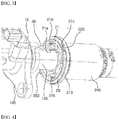
FIG. 1 is a perspective view of a master cylinder in which a brake light sensor module according to an embodiment of a present invention is installed. -
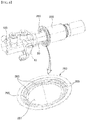
FIG. 2 is a sectional view of a master cylinder in which a brake light sensor module according to an embodiment of a present invention is installed. -
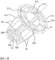
FIG. 3 shows a state in which a retainer and an operation rod of a brake light sensor module according to an embodiment of a present invention is installed in a power piston. -
FIG. 4 is a perspective view of a retainer of a brake light sensor module according to an embodiment of a present invention. -
FIG. 5 is a perspective view of a retainer of a brake light sensor module according to another embodiment of a present invention. -
FIG. 6 is a perspective view of a retainer of a brake light sensor module according to yet another embodiment of a present invention. -
FIG. 7 is a perspective view of a retainer of a brake light sensor module according to yet another embodiment of a present invention. -
FIG. 8 is a perspective view of a retainer of a brake light sensor module according to yet another embodiment of a present invention. -
FIG. 9 andFIG. 10 show a state in which a retainer ofFIG. 8 is installed. - Embodiments of present invention will be explained hereinafter referring to the accompanying drawings.
- Referring to
FIG. 1 to FIG. 3 , asensor 10 which generates a signal for turning on/ off a brake light is installed in amaster cylinder 100. - A
retainer 20 is mounted to an operation element of themaster cylinder 100, i. e., apower piston 200 so as to move together with thepower piston 200 in response to a depression of a brake pedal, and anoperation rod 30 is connected to theretainer 20 so as to move together with theretainer 20. - Further, as shown in
FIG. 2 , anelastic member 40 is disposed to be supported by ahousing 110 of themaster cylinder 100. Theelastic member 40 may be a coil spring. - Meanwhile, a
signal transmitting element 50 is movably disposed in themaster cylinder 100. Thesignal transmitting element 50 may be a member which can transmit a signal for operating thesensor 10, and may be a magnet. Hereinafter, a member designated byreference numeral 50 will be referred to a magnet. - As shown in
FIG. 2 , themagnet 50 may be movably disposed in a state that one side of themagnet 50 is elastically supported by theelastic member 40 and the other side thereof is supported by theoperation rod 30. For example, referring toFIG. 2 , aninsertion hole 110 is formed in themaster cylinder 100 by being elongated in a direction parallel to a moving direction of thepower piston 200, and themagnet 50 may be movably disposed in theinsertion hole 110. Remaining side of theelastic member 40 may be supported by aball 70 which is disposed in theinsertion hole 110. - The
sensor 10 may be a sensor which is operated by themagnet 50 and detects at least one of a position and a moving distance of themagnet 50. Thesensor 10 may output a signal corresponding to a position of themagnet 50. - The
master cylinder 100 and thepower piston 200 may be the same with the prior art, and themaster cylinder 100 and thepower piston 200 are supported to one another via areturn spring 300. Thepower piston 200 is an element which moves toward themaster cylinder 100 in response to the depression of a brake pedal. - If the
power piston 200 moves in response to the depression of the brake pedal, theretainer 20 moves together with thepower piston 200 and thereby theoperation rod 30 also moves. If theoperation rod 30 moves, themagnet 50 which is supported thereto overcomes the elastic power of theelastic member 40 so as to move. Thesensor 10 operates by the movement of themagnet 50 and outputs a corresponding signal, and a brake light may be configured to be turned on by this signal. - A retainer of a brake light sensor module according to an embodiment of the present invention will be described in detail hereinafter referring to the accompanying drawings.
- Referring to
FIG. 3 to FIG. 5 , theretainer 20 includes an operationrod supporting portion 21, a reactionrod supporting portion 23, andribs 25 which connect the operationrod supporting portion 21 and the reactionrod supporting portion 23. - The operation
rod supporting portion 21 is connected to anopening side 210 of thepower piston 200, and theoperation rod 30 is connected to the operationrod supporting portion 21 to be supported by the same. The operationrod supporting portion 21 has a throughhole 21a at a center portion thereof to have a ring shape, and apiston 120 of themaster cylinder 100 is disposed in a state of passing through the throughhole 21a of the operationrod supporting portion 21. - An
air passage 21b may be formed in the operationrod supporting portion 21. Theair passage 21b is formed to maintain vacuum level so as to allow themaster cylinder 100 to operate smoothly. Theair passage 21b may be formed in plural, and the plurality of theair passages 21b may be disposed in a circumferential direction with a constant distance therebetween. - Meanwhile, the
fixing indentation 21c for the connection with thepower piston 200 may be formed at an outer edge area of the operationrod supporting area 21. A fixingprotrusion 220 of thepower piston 200 is fitted into the fixingindentation 21c, and thereby the operationrod supporting portion 21 may be fixed to thepower piston 200. - The reaction
rod supporting portion 23 is disposed within thepower piston 200 and supports areaction rod 230. A throughhole 23a is formed at a center area of the reactionrod supporting portion 23, and thereaction rod 230 passes through the throughhole 23a and is supported by the reactionrod supporting portion 23. - Meanwhile, an
air passage 23b is formed in the reactionrod supporting portion 23. Theair passage 23b may be provided in plural, and the plurality of theair passages 23b may be disposed in a circumferential direction with a constant distance therebetween. - The operation
rod supporting portion 21 and the reactionrod supporting portion 23 are connected to one another by therib 25. Therib 25 may be provided in plural, and the plurality of theribs 25 may be disposed in a circumferential direction with a constant distance therebetween. - Retainers according to other embodiments of the present invention will be described hereinafter referring to
FIG. 5 to FIG. 9 . The retainers according to these embodiments are connected to an opening side of the power piston and has a ring shape to have a through hole at a center portion thereof. - First, referring to
FIG. 5 , aretainer 250 is formed to be connected to theopening side 210 of thepower piston 200 and is provided with a throughhole 251 at a center portion thereof. Theretainer 250 is provided with anindentation 253 into which one end of theoperation rod 30 is fitted. - Meanwhile, an
inner edge portion 255 of theretainer 250 may be inclined to be retracted toward the outside of theopening portion 210 of thepower piston 200. - Referring to
FIG. 6 , aretainer 260 is configured to be connected to theopening portion 210 of thepower piston 200 and is provided with a throughhole 261 at a center portion thereof. Theretainer 260 includes an operationrod supporting portion 263 which supports one end of theoperation rod 30 and an assemblingguide portion 265. The assemblingguide portion 265 plays a role of making the assembling with thepower piston 200 easy. - Referring to
FIG. 7 , aretainer 270 is configured to be connected to theopening portion 210 of thepower piston 200 and is provided with a throughhole 271 at a center portion thereof. Theretainer 270 includes an operationrod supporting portion 273 which supports one end of theoperation rod 30 and an assemblingguide portion 275. The assemblingguide portion 275 plays a role of making the assembling with thepower piston 200 easy. Further, aprotrusion 277 for being fixed with the power piston for the connection with the power piston 299 may be provided at an outer edge portion of theretainer 270. As shown inFIG. 7 , theprotrusion 277 may be formed by being protruded in a radially inward direction, and theprotrusion 277 is fitted into aconnection groove 241 which is formed on an outer surface of thepower piston 200, thus theretainer 270 is stably connected to thepower piston 200. - Another embodiment of the present invention will be described referring to
FIG. 8 to FIG. 10 hereinafter. - As shown in
FIG. 8 , aretainer 280 is configured to be connected to theopening portion 210 of thepower piston 200 and is provided with a throughhole 281 at a center portion thereof. At this time, as shown inFIG. 8 , theretainer 280 has a ring shape in which a circumferential portion of a ring has been removed. Theretainer 280 is provided with atool insertion hole 283. Theretainer 280 may be coupled to thepower piston 200 in a state of being retracted by a tool which is inserted into thetool insertion hole 283. - Referring to
FIG. 9 andFIG. 10 , theretainer 280 is installed to the opening portion 201 of thepower piston 200. At this time, anindentation 251 is formed on an inner surface of thepower piston 200, and theretainer 280 is elastically supported by anelastic member 290 which is disposed in theindentation 251. That is, referring toFIG. 9 andFIG. 10 , one end of theelastic member 290 is supported against awall 261 defining theindentation 251 and the other end thereof supports theretainer 280. Further, theoperation rod 30 is disposed to be supported by theretainer 280. - While this invention has been described in connection with what is presently considered to be practical exemplary embodiments, it is to be understood that the invention is not limited to the disclosed embodiments, but, on the contrary, is intended to cover various modifications and equivalent arrangements included within the spirit and scope of the appended claims.
- The present invention relates to a brake light sensor module and can be applied to a vehicle so as to have an industrial applicability.
Claims (14)
- A brake light sensor module comprising:a retainer which is provided to move together with an operation element of a master cylinder in response to a depression of a brake pedal;an operation rod which is connected to the retainer so as to move together with the retainer;an elastic member which is installed in the master cylinder;a signal transmitting element which is installed in the master cylinder, one end of the signal transmitting element being elastically supported by the elastic member, and the other end of the signal transmitting element being supported by the operation rod; anda sensor which is installed in the master cylinder so as to be operated by the signal transmitting element.
- The brake light sensor module of claim 1, wherein the master cylinder is provided with an insertion hole which is elongated in a direction parallel to a moving direction of the operation element, and the signal transmitting element is movably disposed in the insertion hole.
- The brake light sensor module of claim 1, wherein the operation element is a power piston, and
wherein the retainer comprises:an operation rod supporting portion which is connected to an opening side of the power piston and to which the operation rod is connected;a reaction rod supporting portion which is disposed within the power piston and supports the reaction rod; anda rib which connects the operation rod supporting portion and the reaction rod supporting portion together. - The brake light sensor module of claim 3, wherein an air passage is formed in the operation rod supporting portion.
- The brake light sensor module of claim 3, wherein the operation rod supporting portion has a ring shape having a through hole at a center portion thereof and is provided with a fixing indentation for a connection with the power piston at an outer edge area thereof.
- The brake light sensor module of claim 3, wherein an air passage is formed in the reaction rod supporting portion.
- The brake light sensor module of claim 1, wherein the operation rod is a power piston and the retainer is connected to an opening side of the power piston and has a ring shape having a through hole at a center portion thereof.
- The brake light sensor module of claim 7, wherein the retainer is provided with an indentation into which an end of the operation rod is fitted.
- The brake light sensor module of claim 7, wherein an inner edge portion of the retainer is inclined to be retracted toward the outside of the opening portion of the power piston.
- The brake light sensor module of claim 7, wherein an inner edge portion of the retainer has an operation rod supporting portion which supports an end of the operation rod and an assembling guide portion.
- The brake light sensor module of claim 7, wherein a protrusion for the connection with the power piston is provided at an outer edge portion of the retainer.
- The brake light sensor module of claim 7, wherein the retainer has a ring shape in which a circumferential portion has been removed.
- The brake light sensor module of claim 12, wherein the retainer is provided with a tool insertion hole.
- The brake light sensor module of claim 13, wherein an indentation is formed on an inner surface of the power piston, wherein the retainer is disposed in the indentation, and further comprising an elastic member which is disposed in the indentation to elastically support the retainer.
Applications Claiming Priority (2)
| Application Number | Priority Date | Filing Date | Title |
|---|---|---|---|
| KR1020140024921A KR101447165B1 (en) | 2014-03-03 | 2014-03-03 | Brake light sensor module |
| PCT/KR2015/001895 WO2015133764A1 (en) | 2014-03-03 | 2015-02-26 | Brake light sensor module |
Publications (3)
| Publication Number | Publication Date |
|---|---|
| EP3100911A1 true EP3100911A1 (en) | 2016-12-07 |
| EP3100911A4 EP3100911A4 (en) | 2017-10-11 |
| EP3100911B1 EP3100911B1 (en) | 2020-09-16 |
Family
ID=51996513
Family Applications (1)
| Application Number | Title | Priority Date | Filing Date |
|---|---|---|---|
| EP15759164.5A Active EP3100911B1 (en) | 2014-03-03 | 2015-02-26 | Brake light sensor module |
Country Status (5)
| Country | Link |
|---|---|
| US (1) | US10173587B2 (en) |
| EP (1) | EP3100911B1 (en) |
| KR (1) | KR101447165B1 (en) |
| CN (1) | CN106103190B (en) |
| WO (1) | WO2015133764A1 (en) |
Families Citing this family (4)
| Publication number | Priority date | Publication date | Assignee | Title |
|---|---|---|---|---|
| KR101657567B1 (en) * | 2015-05-18 | 2016-09-19 | 주식회사 만도 | Brake Light Sensor module integrated for master cylinder |
| KR101641133B1 (en) * | 2015-09-30 | 2016-07-20 | 이래오토모티브시스템 주식회사 | Brake light sensor module |
| WO2017057914A1 (en) * | 2015-09-30 | 2017-04-06 | 이래오토모티브시스템 주식회사 | Brake light sensor module |
| KR102689145B1 (en) * | 2019-09-16 | 2024-07-29 | 현대모비스 주식회사 | Sensing apparatus for pedal stroke |
Family Cites Families (16)
| Publication number | Priority date | Publication date | Assignee | Title |
|---|---|---|---|---|
| US5142965A (en) * | 1991-08-28 | 1992-09-01 | Allied-Signal Inc. | Master cylinder piston retainer |
| FR2829737B1 (en) * | 2001-09-20 | 2003-12-19 | Bosch Gmbh Robert | TANDEM MASTER CYLINDER FOR ELECTROHYDRAULIC BRAKING SYSTEMS |
| DE102004029193B4 (en) * | 2004-06-16 | 2007-09-13 | Hartmann-Exact Gmbh | Method and device for detecting an operating parameter triggering a specific function |
| DE102005018649B4 (en) * | 2005-04-21 | 2018-10-31 | Ipgate Ag | Brake system with electric motor-driven piston-cylinder system |
| CN201002610Y (en) * | 2006-12-22 | 2008-01-09 | 吉林汽车制动器厂 | Automobile brake master cylinder with brake lamp sensor |
| FR2913937B1 (en) * | 2007-03-22 | 2009-05-01 | Bosch Gmbh Robert | METHOD AND SERVOMOTOR FOR DETECTING THE BRAKE OF A VEHICLE AND METHOD OF MANUFACTURING SUCH A SERVOMOTOR |
| FR2919251B1 (en) * | 2007-07-23 | 2009-12-18 | Bosch Gmbh Robert | DEVICE FOR DETECTING BRAKE AND CONTROLLING REAR LIGHTS OF A VEHICLE. |
| KR20090101556A (en) * | 2008-03-24 | 2009-09-29 | 주식회사 만도 | Master cylinder of brake for vehicles |
| DE102008020934A1 (en) * | 2008-04-25 | 2009-10-29 | Lucas Automotive Gmbh | Master brake cylinder arrangement with actuation detection for a motor vehicle brake system and motor vehicle brake system |
| FR2938810B1 (en) * | 2008-11-25 | 2010-11-19 | Bosch Gmbh Robert | MASTER CYLINDER AND METHOD FOR ASSEMBLING SUCH A MASTER CYLINDER |
| FR2962391A1 (en) * | 2010-07-12 | 2012-01-13 | Bosch Gmbh Robert | MASTER-CYLINDER DEVICE FOR MOTOR VEHICLE |
| DE102010027308A1 (en) * | 2010-07-16 | 2012-01-19 | Lucas Automotive Gmbh | Sensor assembly for a master cylinder |
| DE102010062163A1 (en) * | 2010-11-30 | 2012-05-31 | Continental Teves Ag & Co. Ohg | Device for monitoring the position and movement of a brake pedal |
| KR101277557B1 (en) * | 2011-09-16 | 2013-06-21 | 주식회사 만도 | Brake master cylinder |
| KR20130064665A (en) * | 2011-12-08 | 2013-06-18 | 현대모비스 주식회사 | Brake light switch |
| JP5817912B2 (en) * | 2012-03-07 | 2015-11-18 | トヨタ自動車株式会社 | Hydraulic brake system |
-
2014
- 2014-03-03 KR KR1020140024921A patent/KR101447165B1/en active Active
-
2015
- 2015-02-26 EP EP15759164.5A patent/EP3100911B1/en active Active
- 2015-02-26 WO PCT/KR2015/001895 patent/WO2015133764A1/en not_active Ceased
- 2015-02-26 CN CN201580011615.7A patent/CN106103190B/en active Active
- 2015-02-26 US US15/123,391 patent/US10173587B2/en active Active
Also Published As
| Publication number | Publication date |
|---|---|
| CN106103190B (en) | 2018-04-27 |
| WO2015133764A1 (en) | 2015-09-11 |
| EP3100911A4 (en) | 2017-10-11 |
| CN106103190A (en) | 2016-11-09 |
| US20170057406A1 (en) | 2017-03-02 |
| KR101447165B1 (en) | 2014-10-10 |
| US10173587B2 (en) | 2019-01-08 |
| EP3100911B1 (en) | 2020-09-16 |
Similar Documents
| Publication | Publication Date | Title |
|---|---|---|
| US10173587B2 (en) | Brake light sensor module | |
| KR101801536B1 (en) | Installation structure for pedal stroke sensor | |
| US9592783B2 (en) | Steering wheel unit | |
| US10173649B2 (en) | Brake master cylinder | |
| WO2015182464A1 (en) | Cup holder | |
| KR20130132273A (en) | Vehicular lamp | |
| JP6049074B2 (en) | Waterproof structure and switch device having waterproof structure | |
| JP2018536121A (en) | Slave cylinder for hydraulic release system that operates friction clutch | |
| CN108025605A (en) | Tire valve unit | |
| US9821786B2 (en) | Drive assembly | |
| JP6333205B2 (en) | Tire valve | |
| US20180202836A1 (en) | Position sensor | |
| KR102394154B1 (en) | Oil pressure generator for brake system | |
| US20150168180A1 (en) | Optical encoder having stationary slit part made of resin | |
| KR101560622B1 (en) | Master cylinder | |
| JP2019175910A (en) | Cover, seal mounting device, and seal mounting method | |
| JP5307666B2 (en) | Fastener | |
| JP4407545B2 (en) | Vehicle interior lighting device | |
| JP3194921U (en) | Rear view mirror | |
| JP5955256B2 (en) | Enclosure | |
| JP2014101894A (en) | Sensor fixture | |
| KR101524489B1 (en) | Linear sensor | |
| WO2016038559A1 (en) | Electromechanical switch assembly | |
| JP5334788B2 (en) | Solid state switch | |
| CN106969312B (en) | Lighting and/or signaling devices for motor vehicles |
Legal Events
| Date | Code | Title | Description |
|---|---|---|---|
| PUAI | Public reference made under article 153(3) epc to a published international application that has entered the european phase |
Free format text: ORIGINAL CODE: 0009012 |
|
| STAA | Information on the status of an ep patent application or granted ep patent |
Free format text: STATUS: REQUEST FOR EXAMINATION WAS MADE |
|
| 17P | Request for examination filed |
Effective date: 20160902 |
|
| AK | Designated contracting states |
Kind code of ref document: A1 Designated state(s): AL AT BE BG CH CY CZ DE DK EE ES FI FR GB GR HR HU IE IS IT LI LT LU LV MC MK MT NL NO PL PT RO RS SE SI SK SM TR |
|
| AX | Request for extension of the european patent |
Extension state: BA ME |
|
| RIN1 | Information on inventor provided before grant (corrected) |
Inventor name: KIM, SANG-BO Inventor name: HAN, DONG-HAN Inventor name: ROH, CHUL-KYUN |
|
| DAX | Request for extension of the european patent (deleted) | ||
| A4 | Supplementary search report drawn up and despatched |
Effective date: 20170912 |
|
| RIC1 | Information provided on ipc code assigned before grant |
Ipc: B60Q 11/00 20060101ALI20170906BHEP Ipc: B60T 7/04 20060101ALI20170906BHEP Ipc: B60T 17/22 20060101ALI20170906BHEP Ipc: B60Q 1/44 20060101AFI20170906BHEP |
|
| RAP1 | Party data changed (applicant data changed or rights of an application transferred) |
Owner name: ERAE AMS CO., LTD. |
|
| GRAP | Despatch of communication of intention to grant a patent |
Free format text: ORIGINAL CODE: EPIDOSNIGR1 |
|
| STAA | Information on the status of an ep patent application or granted ep patent |
Free format text: STATUS: GRANT OF PATENT IS INTENDED |
|
| INTG | Intention to grant announced |
Effective date: 20200330 |
|
| GRAS | Grant fee paid |
Free format text: ORIGINAL CODE: EPIDOSNIGR3 |
|
| GRAA | (expected) grant |
Free format text: ORIGINAL CODE: 0009210 |
|
| STAA | Information on the status of an ep patent application or granted ep patent |
Free format text: STATUS: THE PATENT HAS BEEN GRANTED |
|
| AK | Designated contracting states |
Kind code of ref document: B1 Designated state(s): AL AT BE BG CH CY CZ DE DK EE ES FI FR GB GR HR HU IE IS IT LI LT LU LV MC MK MT NL NO PL PT RO RS SE SI SK SM TR |
|
| REG | Reference to a national code |
Ref country code: GB Ref legal event code: FG4D |
|
| REG | Reference to a national code |
Ref country code: CH Ref legal event code: EP |
|
| REG | Reference to a national code |
Ref country code: DE Ref legal event code: R096 Ref document number: 602015059183 Country of ref document: DE |
|
| REG | Reference to a national code |
Ref country code: IE Ref legal event code: FG4D |
|
| REG | Reference to a national code |
Ref country code: AT Ref legal event code: REF Ref document number: 1313886 Country of ref document: AT Kind code of ref document: T Effective date: 20201015 |
|
| PG25 | Lapsed in a contracting state [announced via postgrant information from national office to epo] |
Ref country code: NO Free format text: LAPSE BECAUSE OF FAILURE TO SUBMIT A TRANSLATION OF THE DESCRIPTION OR TO PAY THE FEE WITHIN THE PRESCRIBED TIME-LIMIT Effective date: 20201216 Ref country code: GR Free format text: LAPSE BECAUSE OF FAILURE TO SUBMIT A TRANSLATION OF THE DESCRIPTION OR TO PAY THE FEE WITHIN THE PRESCRIBED TIME-LIMIT Effective date: 20201217 Ref country code: SE Free format text: LAPSE BECAUSE OF FAILURE TO SUBMIT A TRANSLATION OF THE DESCRIPTION OR TO PAY THE FEE WITHIN THE PRESCRIBED TIME-LIMIT Effective date: 20200916 Ref country code: BG Free format text: LAPSE BECAUSE OF FAILURE TO SUBMIT A TRANSLATION OF THE DESCRIPTION OR TO PAY THE FEE WITHIN THE PRESCRIBED TIME-LIMIT Effective date: 20201216 Ref country code: HR Free format text: LAPSE BECAUSE OF FAILURE TO SUBMIT A TRANSLATION OF THE DESCRIPTION OR TO PAY THE FEE WITHIN THE PRESCRIBED TIME-LIMIT Effective date: 20200916 Ref country code: FI Free format text: LAPSE BECAUSE OF FAILURE TO SUBMIT A TRANSLATION OF THE DESCRIPTION OR TO PAY THE FEE WITHIN THE PRESCRIBED TIME-LIMIT Effective date: 20200916 |
|
| REG | Reference to a national code |
Ref country code: AT Ref legal event code: MK05 Ref document number: 1313886 Country of ref document: AT Kind code of ref document: T Effective date: 20200916 |
|
| REG | Reference to a national code |
Ref country code: NL Ref legal event code: MP Effective date: 20200916 |
|
| PG25 | Lapsed in a contracting state [announced via postgrant information from national office to epo] |
Ref country code: LV Free format text: LAPSE BECAUSE OF FAILURE TO SUBMIT A TRANSLATION OF THE DESCRIPTION OR TO PAY THE FEE WITHIN THE PRESCRIBED TIME-LIMIT Effective date: 20200916 Ref country code: RS Free format text: LAPSE BECAUSE OF FAILURE TO SUBMIT A TRANSLATION OF THE DESCRIPTION OR TO PAY THE FEE WITHIN THE PRESCRIBED TIME-LIMIT Effective date: 20200916 |
|
| REG | Reference to a national code |
Ref country code: LT Ref legal event code: MG4D |
|
| PG25 | Lapsed in a contracting state [announced via postgrant information from national office to epo] |
Ref country code: NL Free format text: LAPSE BECAUSE OF FAILURE TO SUBMIT A TRANSLATION OF THE DESCRIPTION OR TO PAY THE FEE WITHIN THE PRESCRIBED TIME-LIMIT Effective date: 20200916 Ref country code: LT Free format text: LAPSE BECAUSE OF FAILURE TO SUBMIT A TRANSLATION OF THE DESCRIPTION OR TO PAY THE FEE WITHIN THE PRESCRIBED TIME-LIMIT Effective date: 20200916 Ref country code: EE Free format text: LAPSE BECAUSE OF FAILURE TO SUBMIT A TRANSLATION OF THE DESCRIPTION OR TO PAY THE FEE WITHIN THE PRESCRIBED TIME-LIMIT Effective date: 20200916 Ref country code: SM Free format text: LAPSE BECAUSE OF FAILURE TO SUBMIT A TRANSLATION OF THE DESCRIPTION OR TO PAY THE FEE WITHIN THE PRESCRIBED TIME-LIMIT Effective date: 20200916 Ref country code: RO Free format text: LAPSE BECAUSE OF FAILURE TO SUBMIT A TRANSLATION OF THE DESCRIPTION OR TO PAY THE FEE WITHIN THE PRESCRIBED TIME-LIMIT Effective date: 20200916 Ref country code: PT Free format text: LAPSE BECAUSE OF FAILURE TO SUBMIT A TRANSLATION OF THE DESCRIPTION OR TO PAY THE FEE WITHIN THE PRESCRIBED TIME-LIMIT Effective date: 20210118 Ref country code: CZ Free format text: LAPSE BECAUSE OF FAILURE TO SUBMIT A TRANSLATION OF THE DESCRIPTION OR TO PAY THE FEE WITHIN THE PRESCRIBED TIME-LIMIT Effective date: 20200916 |
|
| PG25 | Lapsed in a contracting state [announced via postgrant information from national office to epo] |
Ref country code: AL Free format text: LAPSE BECAUSE OF FAILURE TO SUBMIT A TRANSLATION OF THE DESCRIPTION OR TO PAY THE FEE WITHIN THE PRESCRIBED TIME-LIMIT Effective date: 20200916 Ref country code: AT Free format text: LAPSE BECAUSE OF FAILURE TO SUBMIT A TRANSLATION OF THE DESCRIPTION OR TO PAY THE FEE WITHIN THE PRESCRIBED TIME-LIMIT Effective date: 20200916 Ref country code: ES Free format text: LAPSE BECAUSE OF FAILURE TO SUBMIT A TRANSLATION OF THE DESCRIPTION OR TO PAY THE FEE WITHIN THE PRESCRIBED TIME-LIMIT Effective date: 20200916 Ref country code: IS Free format text: LAPSE BECAUSE OF FAILURE TO SUBMIT A TRANSLATION OF THE DESCRIPTION OR TO PAY THE FEE WITHIN THE PRESCRIBED TIME-LIMIT Effective date: 20210116 Ref country code: PL Free format text: LAPSE BECAUSE OF FAILURE TO SUBMIT A TRANSLATION OF THE DESCRIPTION OR TO PAY THE FEE WITHIN THE PRESCRIBED TIME-LIMIT Effective date: 20200916 |
|
| REG | Reference to a national code |
Ref country code: DE Ref legal event code: R097 Ref document number: 602015059183 Country of ref document: DE |
|
| PG25 | Lapsed in a contracting state [announced via postgrant information from national office to epo] |
Ref country code: SK Free format text: LAPSE BECAUSE OF FAILURE TO SUBMIT A TRANSLATION OF THE DESCRIPTION OR TO PAY THE FEE WITHIN THE PRESCRIBED TIME-LIMIT Effective date: 20200916 |
|
| PLBE | No opposition filed within time limit |
Free format text: ORIGINAL CODE: 0009261 |
|
| STAA | Information on the status of an ep patent application or granted ep patent |
Free format text: STATUS: NO OPPOSITION FILED WITHIN TIME LIMIT |
|
| 26N | No opposition filed |
Effective date: 20210617 |
|
| PG25 | Lapsed in a contracting state [announced via postgrant information from national office to epo] |
Ref country code: DK Free format text: LAPSE BECAUSE OF FAILURE TO SUBMIT A TRANSLATION OF THE DESCRIPTION OR TO PAY THE FEE WITHIN THE PRESCRIBED TIME-LIMIT Effective date: 20200916 Ref country code: SI Free format text: LAPSE BECAUSE OF FAILURE TO SUBMIT A TRANSLATION OF THE DESCRIPTION OR TO PAY THE FEE WITHIN THE PRESCRIBED TIME-LIMIT Effective date: 20200916 |
|
| PG25 | Lapsed in a contracting state [announced via postgrant information from national office to epo] |
Ref country code: MC Free format text: LAPSE BECAUSE OF FAILURE TO SUBMIT A TRANSLATION OF THE DESCRIPTION OR TO PAY THE FEE WITHIN THE PRESCRIBED TIME-LIMIT Effective date: 20200916 |
|
| GBPC | Gb: european patent ceased through non-payment of renewal fee |
Effective date: 20210226 |
|
| REG | Reference to a national code |
Ref country code: BE Ref legal event code: MM Effective date: 20210228 |
|
| PG25 | Lapsed in a contracting state [announced via postgrant information from national office to epo] |
Ref country code: LI Free format text: LAPSE BECAUSE OF NON-PAYMENT OF DUE FEES Effective date: 20210228 Ref country code: LU Free format text: LAPSE BECAUSE OF NON-PAYMENT OF DUE FEES Effective date: 20210226 Ref country code: IT Free format text: LAPSE BECAUSE OF FAILURE TO SUBMIT A TRANSLATION OF THE DESCRIPTION OR TO PAY THE FEE WITHIN THE PRESCRIBED TIME-LIMIT Effective date: 20200916 Ref country code: CH Free format text: LAPSE BECAUSE OF NON-PAYMENT OF DUE FEES Effective date: 20210228 |
|
| PG25 | Lapsed in a contracting state [announced via postgrant information from national office to epo] |
Ref country code: FR Free format text: LAPSE BECAUSE OF NON-PAYMENT OF DUE FEES Effective date: 20210228 Ref country code: IE Free format text: LAPSE BECAUSE OF NON-PAYMENT OF DUE FEES Effective date: 20210226 Ref country code: GB Free format text: LAPSE BECAUSE OF NON-PAYMENT OF DUE FEES Effective date: 20210226 |
|
| PG25 | Lapsed in a contracting state [announced via postgrant information from national office to epo] |
Ref country code: BE Free format text: LAPSE BECAUSE OF NON-PAYMENT OF DUE FEES Effective date: 20210228 |
|
| PG25 | Lapsed in a contracting state [announced via postgrant information from national office to epo] |
Ref country code: HU Free format text: LAPSE BECAUSE OF FAILURE TO SUBMIT A TRANSLATION OF THE DESCRIPTION OR TO PAY THE FEE WITHIN THE PRESCRIBED TIME-LIMIT; INVALID AB INITIO Effective date: 20150226 |
|
| PG25 | Lapsed in a contracting state [announced via postgrant information from national office to epo] |
Ref country code: CY Free format text: LAPSE BECAUSE OF FAILURE TO SUBMIT A TRANSLATION OF THE DESCRIPTION OR TO PAY THE FEE WITHIN THE PRESCRIBED TIME-LIMIT Effective date: 20200916 |
|
| PG25 | Lapsed in a contracting state [announced via postgrant information from national office to epo] |
Ref country code: MK Free format text: LAPSE BECAUSE OF FAILURE TO SUBMIT A TRANSLATION OF THE DESCRIPTION OR TO PAY THE FEE WITHIN THE PRESCRIBED TIME-LIMIT Effective date: 20200916 |
|
| PG25 | Lapsed in a contracting state [announced via postgrant information from national office to epo] |
Ref country code: TR Free format text: LAPSE BECAUSE OF FAILURE TO SUBMIT A TRANSLATION OF THE DESCRIPTION OR TO PAY THE FEE WITHIN THE PRESCRIBED TIME-LIMIT Effective date: 20200916 |
|
| PG25 | Lapsed in a contracting state [announced via postgrant information from national office to epo] |
Ref country code: MT Free format text: LAPSE BECAUSE OF FAILURE TO SUBMIT A TRANSLATION OF THE DESCRIPTION OR TO PAY THE FEE WITHIN THE PRESCRIBED TIME-LIMIT Effective date: 20200916 |
|
| REG | Reference to a national code |
Ref country code: DE Ref legal event code: R081 Ref document number: 602015059183 Country of ref document: DE Owner name: HANSAE MOBILITY CO., LTD., DAEGU, KR Free format text: FORMER OWNER: ERAE AMS CO., LTD., DAEGU, KR |
|
| PGFP | Annual fee paid to national office [announced via postgrant information from national office to epo] |
Ref country code: DE Payment date: 20260102 Year of fee payment: 12 |