EP3100901A1 - Adaptable vehicle seat anchorage - Google Patents
Adaptable vehicle seat anchorage Download PDFInfo
- Publication number
- EP3100901A1 EP3100901A1 EP16171615.4A EP16171615A EP3100901A1 EP 3100901 A1 EP3100901 A1 EP 3100901A1 EP 16171615 A EP16171615 A EP 16171615A EP 3100901 A1 EP3100901 A1 EP 3100901A1
- Authority
- EP
- European Patent Office
- Prior art keywords
- track
- seat support
- bracing
- protrusions
- locking
- Prior art date
- Legal status (The legal status is an assumption and is not a legal conclusion. Google has not performed a legal analysis and makes no representation as to the accuracy of the status listed.)
- Withdrawn
Links
- 230000001419 dependent effect Effects 0.000 claims 1
- 230000007246 mechanism Effects 0.000 description 31
- 230000009471 action Effects 0.000 description 5
- 239000000463 material Substances 0.000 description 4
- 210000005069 ears Anatomy 0.000 description 3
- 229910000831 Steel Inorganic materials 0.000 description 2
- 230000006835 compression Effects 0.000 description 2
- 238000007906 compression Methods 0.000 description 2
- 238000000034 method Methods 0.000 description 2
- 239000010959 steel Substances 0.000 description 2
- 238000005728 strengthening Methods 0.000 description 2
- 238000001125 extrusion Methods 0.000 description 1
- 230000008569 process Effects 0.000 description 1
Images



Classifications
-
- B—PERFORMING OPERATIONS; TRANSPORTING
- B60—VEHICLES IN GENERAL
- B60N—SEATS SPECIALLY ADAPTED FOR VEHICLES; VEHICLE PASSENGER ACCOMMODATION NOT OTHERWISE PROVIDED FOR
- B60N2/00—Seats specially adapted for vehicles; Arrangement or mounting of seats in vehicles
- B60N2/02—Seats specially adapted for vehicles; Arrangement or mounting of seats in vehicles the seat or part thereof being movable, e.g. adjustable
- B60N2/04—Seats specially adapted for vehicles; Arrangement or mounting of seats in vehicles the seat or part thereof being movable, e.g. adjustable the whole seat being movable
- B60N2/06—Seats specially adapted for vehicles; Arrangement or mounting of seats in vehicles the seat or part thereof being movable, e.g. adjustable the whole seat being movable slidable
- B60N2/07—Slide construction
- B60N2/0722—Constructive details
-
- B—PERFORMING OPERATIONS; TRANSPORTING
- B60—VEHICLES IN GENERAL
- B60N—SEATS SPECIALLY ADAPTED FOR VEHICLES; VEHICLE PASSENGER ACCOMMODATION NOT OTHERWISE PROVIDED FOR
- B60N2/00—Seats specially adapted for vehicles; Arrangement or mounting of seats in vehicles
- B60N2/005—Arrangement or mounting of seats in vehicles, e.g. dismountable auxiliary seats
- B60N2/015—Attaching seats directly to vehicle chassis
-
- B—PERFORMING OPERATIONS; TRANSPORTING
- B60—VEHICLES IN GENERAL
- B60N—SEATS SPECIALLY ADAPTED FOR VEHICLES; VEHICLE PASSENGER ACCOMMODATION NOT OTHERWISE PROVIDED FOR
- B60N2/00—Seats specially adapted for vehicles; Arrangement or mounting of seats in vehicles
- B60N2/005—Arrangement or mounting of seats in vehicles, e.g. dismountable auxiliary seats
- B60N2/015—Attaching seats directly to vehicle chassis
- B60N2/01508—Attaching seats directly to vehicle chassis using quick release attachments
- B60N2/01516—Attaching seats directly to vehicle chassis using quick release attachments with locking mechanisms
- B60N2/01525—Attaching seats directly to vehicle chassis using quick release attachments with locking mechanisms with locking elements expanding inside or under the vehicle floor or rail
-
- B—PERFORMING OPERATIONS; TRANSPORTING
- B60—VEHICLES IN GENERAL
- B60N—SEATS SPECIALLY ADAPTED FOR VEHICLES; VEHICLE PASSENGER ACCOMMODATION NOT OTHERWISE PROVIDED FOR
- B60N2/00—Seats specially adapted for vehicles; Arrangement or mounting of seats in vehicles
- B60N2/005—Arrangement or mounting of seats in vehicles, e.g. dismountable auxiliary seats
- B60N2/015—Attaching seats directly to vehicle chassis
- B60N2/01508—Attaching seats directly to vehicle chassis using quick release attachments
- B60N2/01516—Attaching seats directly to vehicle chassis using quick release attachments with locking mechanisms
- B60N2/0155—Attaching seats directly to vehicle chassis using quick release attachments with locking mechanisms with the locking mechanism on the vehicle floor or rail
-
- B—PERFORMING OPERATIONS; TRANSPORTING
- B60—VEHICLES IN GENERAL
- B60N—SEATS SPECIALLY ADAPTED FOR VEHICLES; VEHICLE PASSENGER ACCOMMODATION NOT OTHERWISE PROVIDED FOR
- B60N2/00—Seats specially adapted for vehicles; Arrangement or mounting of seats in vehicles
- B60N2/005—Arrangement or mounting of seats in vehicles, e.g. dismountable auxiliary seats
- B60N2/015—Attaching seats directly to vehicle chassis
- B60N2/01508—Attaching seats directly to vehicle chassis using quick release attachments
- B60N2/01516—Attaching seats directly to vehicle chassis using quick release attachments with locking mechanisms
- B60N2/01558—Attaching seats directly to vehicle chassis using quick release attachments with locking mechanisms with key and slot
- B60N2/01575—Attaching seats directly to vehicle chassis using quick release attachments with locking mechanisms with key and slot key sliding inside the vehicle floor or rail
-
- B—PERFORMING OPERATIONS; TRANSPORTING
- B60—VEHICLES IN GENERAL
- B60N—SEATS SPECIALLY ADAPTED FOR VEHICLES; VEHICLE PASSENGER ACCOMMODATION NOT OTHERWISE PROVIDED FOR
- B60N2/00—Seats specially adapted for vehicles; Arrangement or mounting of seats in vehicles
- B60N2/02—Seats specially adapted for vehicles; Arrangement or mounting of seats in vehicles the seat or part thereof being movable, e.g. adjustable
- B60N2/04—Seats specially adapted for vehicles; Arrangement or mounting of seats in vehicles the seat or part thereof being movable, e.g. adjustable the whole seat being movable
- B60N2/06—Seats specially adapted for vehicles; Arrangement or mounting of seats in vehicles the seat or part thereof being movable, e.g. adjustable the whole seat being movable slidable
- B60N2/07—Slide construction
- B60N2/0722—Constructive details
- B60N2/0727—Stop members for limiting sliding movement
-
- B—PERFORMING OPERATIONS; TRANSPORTING
- B60—VEHICLES IN GENERAL
- B60N—SEATS SPECIALLY ADAPTED FOR VEHICLES; VEHICLE PASSENGER ACCOMMODATION NOT OTHERWISE PROVIDED FOR
- B60N2/00—Seats specially adapted for vehicles; Arrangement or mounting of seats in vehicles
- B60N2/02—Seats specially adapted for vehicles; Arrangement or mounting of seats in vehicles the seat or part thereof being movable, e.g. adjustable
- B60N2/04—Seats specially adapted for vehicles; Arrangement or mounting of seats in vehicles the seat or part thereof being movable, e.g. adjustable the whole seat being movable
- B60N2/06—Seats specially adapted for vehicles; Arrangement or mounting of seats in vehicles the seat or part thereof being movable, e.g. adjustable the whole seat being movable slidable
- B60N2/08—Seats specially adapted for vehicles; Arrangement or mounting of seats in vehicles the seat or part thereof being movable, e.g. adjustable the whole seat being movable slidable characterised by the locking device
- B60N2/0806—Seats specially adapted for vehicles; Arrangement or mounting of seats in vehicles the seat or part thereof being movable, e.g. adjustable the whole seat being movable slidable characterised by the locking device with pin alignment systems, e.g. with at least one of a plurality of locking pins always aligned w.r.t. at least one of a plurality of pin-receiving elements
-
- B—PERFORMING OPERATIONS; TRANSPORTING
- B60—VEHICLES IN GENERAL
- B60N—SEATS SPECIALLY ADAPTED FOR VEHICLES; VEHICLE PASSENGER ACCOMMODATION NOT OTHERWISE PROVIDED FOR
- B60N2/00—Seats specially adapted for vehicles; Arrangement or mounting of seats in vehicles
- B60N2/02—Seats specially adapted for vehicles; Arrangement or mounting of seats in vehicles the seat or part thereof being movable, e.g. adjustable
- B60N2/04—Seats specially adapted for vehicles; Arrangement or mounting of seats in vehicles the seat or part thereof being movable, e.g. adjustable the whole seat being movable
- B60N2/06—Seats specially adapted for vehicles; Arrangement or mounting of seats in vehicles the seat or part thereof being movable, e.g. adjustable the whole seat being movable slidable
- B60N2/08—Seats specially adapted for vehicles; Arrangement or mounting of seats in vehicles the seat or part thereof being movable, e.g. adjustable the whole seat being movable slidable characterised by the locking device
- B60N2/0831—Movement of the latch
- B60N2/0862—Movement of the latch sliding
- B60N2/0875—Movement of the latch sliding in a vertical direction
-
- B—PERFORMING OPERATIONS; TRANSPORTING
- B60—VEHICLES IN GENERAL
- B60P—VEHICLES ADAPTED FOR LOAD TRANSPORTATION OR TO TRANSPORT, TO CARRY, OR TO COMPRISE SPECIAL LOADS OR OBJECTS
- B60P7/00—Securing or covering of load on vehicles
- B60P7/06—Securing of load
- B60P7/08—Securing to the vehicle floor or sides
- B60P7/0807—Attachment points
- B60P7/0815—Attachment rails or trellis
-
- B—PERFORMING OPERATIONS; TRANSPORTING
- B64—AIRCRAFT; AVIATION; COSMONAUTICS
- B64D—EQUIPMENT FOR FITTING IN OR TO AIRCRAFT; FLIGHT SUITS; PARACHUTES; ARRANGEMENT OR MOUNTING OF POWER PLANTS OR PROPULSION TRANSMISSIONS IN AIRCRAFT
- B64D11/00—Passenger or crew accommodation; Flight-deck installations not otherwise provided for
- B64D11/06—Arrangements of seats, or adaptations or details specially adapted for aircraft seats
- B64D11/0696—Means for fastening seats to floors, e.g. to floor rails
-
- B—PERFORMING OPERATIONS; TRANSPORTING
- B60—VEHICLES IN GENERAL
- B60N—SEATS SPECIALLY ADAPTED FOR VEHICLES; VEHICLE PASSENGER ACCOMMODATION NOT OTHERWISE PROVIDED FOR
- B60N2/00—Seats specially adapted for vehicles; Arrangement or mounting of seats in vehicles
- B60N2/02—Seats specially adapted for vehicles; Arrangement or mounting of seats in vehicles the seat or part thereof being movable, e.g. adjustable
- B60N2/04—Seats specially adapted for vehicles; Arrangement or mounting of seats in vehicles the seat or part thereof being movable, e.g. adjustable the whole seat being movable
- B60N2/06—Seats specially adapted for vehicles; Arrangement or mounting of seats in vehicles the seat or part thereof being movable, e.g. adjustable the whole seat being movable slidable
- B60N2/08—Seats specially adapted for vehicles; Arrangement or mounting of seats in vehicles the seat or part thereof being movable, e.g. adjustable the whole seat being movable slidable characterised by the locking device
- B60N2/0831—Movement of the latch
- B60N2/0862—Movement of the latch sliding
Definitions
- THE PRESENT INVENTION relates to a seat support, and more specifically relates to a seat support suitable for use in a vehicle such as a motor vehicle.
- US2012/0235011 discloses a type of fitting in which studs protrude from the underside of a main body, and may be retracted towards the main body to grip a part of the track. A plunger may then be pushed down into the track through one of the recesses to brace the fitting against longitudinal movement.
- an alternative seat support is disclosed, which is adapted to be used with a floor track 1 taking the form of an undercut slot 2, with inward-facing opposing lips 3, 4, as shown schematically in figure 1 .
- the lips 3, 4 each have spaced-apart recesses 5 which are curved in shape, and the recesses 5 in the lips 3, 4 are aligned with each other.
- Protrusions 6 are formed between adjacent recesses 5, and each protrusion 6 forms two shoulders 7, 8, one 7 of which faces in the "forwards" direction (i.e. the normal direction of travel of the vehicle), and the other 8 of which faces in the opposite "backwards" direction.
- the seat support of GB2517149 includes first and second locking portions 9, 10, which are also shown schematically in figure 1 .
- first locking portion 9 which is positioned at the front of the support
- second locking portion 10 which is positioned at the rear of the support
- the support is therefore locked longitudinally in place with respect to these shoulders 7, 8, and cannot move forwards or backwards along the track 1.
- the inventor has realised that, if the second locking portion 10 is not properly locked in place (for instance, because the support has been installed by an inexperienced operator), there is a possibility of failure in the event of a head-on collision.
- the second locking portion 10 does not provide adequate resistance, then in the event of a head-on collision the entire support will tend to move in the forward direction with respect to the track 1.
- the first locking portion 9 has, as can be seen in figure 1 , clear space in front of it, and it can slide forward (along with the rest of the support) until it reaches the next pair of rear-facing shoulders 8.
- the present invention seeks to provide an improved seat support, that enjoys the advantages of the design shown in GB2517149 , but is more resistant to failure in a crash situation, particularly where the device may have been installed by an inexperienced operator.
- the present invention provides a seat support for use with a vehicle seat and adapted to engage a track provided on the floor of a vehicle, the track comprising two inwardly-directed lips on opposed sides of a slot, the lips providing first alternating protrusions and recesses along the length of the track, the protrusions being spaced apart by a spacing distance, the first and second protrusions defining shoulder surfaces on each side thereof, the seat support having an elongate main body and comprising: an interface portion which has a profile comprising second alternating protrusions and recesses, the protrusions being spaced apart by the same spacing distance; first and second bracing members; and a locking arrangement, wherein: the seat support is configured such that the second protrusions may be aligned with the first recesses so that the interface portion may be placed within the slot in an engagement position, the seat support being moveable with respect to the slot, from the engagement position into a bracing position in which the first and second protrusions are substantially aligned,
- the track defines a first longitudinal direction and a second substantially opposite longitudinal direction; the first and second pairs of shoulders face in the second direction; and in the bracing position, the bracing of the first and second bracing members against the first and second pairs of shoulders prevents longitudinal movement of the seat support with respect to the track in the first direction.
- the locking arrangement comprises a first clamping member which, in the locking configuration, is biased against an upper surface of the track.
- the seat support further comprises a spring which is located above the first clamping member to bias the first clamping member towards the upper surface of the track.
- the seat support further comprises an operating member which a user may operate to drive the first clamping member against the upper surface of the track.
- the operating member is a lever which is pivotable with respect to the main body.
- the spring is located between the operating member and the first clamping member.
- At least one protrusion of the interface portion is pressed against the underside of at least one of the lips of the track.
- the seat support further comprises a catch arrangement to retain the locking arrangement in the locking configuration.
- the catch arrangement comprises a catch element which, in a retaining position, bears against a further part of the seat support to prevent the locking arrangement from moving from the locking configuration to the release configuration.
- the locking arrangement is moved from the release configuration to the locking configuration, the catch member moves automatically into the retaining position.
- the first bracing member comprises a surface against which the first pair of shoulders may bear.
- the second bracing member comprises a surface against which the second pair of shoulders may bear.
- the second bracing member is substantially fixed in place with respect to the main body of the seat support.
- the first bracing portion contacts a pair of shoulders of the track and acts as a stop, so that the seat support is in the bracing position.
- the first and second recesses overlap.
- the first and second recesses are generally aligned.
- the track is installed in a vehicle which has a normal forward direction of travel, and the track comprises forward-facing shoulders and rearward-facing shoulders, and wherein, in the bracing position, both the first and second bracing elements are braced against respective pairs of rearward-facing shoulders.
- a seat support according to any of the above in combination with a track which comprises: two inwardly-directed lips on opposed sides of a slot, the lips providing first alternating protrusions and recesses along the length of the track, the protrusions being spaced apart by a spacing distance, the first and second protrusions defining shoulder surfaces on each side thereof.
- a further aspect of the present invention provides a seat including a seat support in accordance with any previous claim.
- a track 11 adapted to be mounted in the floor of a motor vehicle is shown, and this track is the same as that discussed above in relation to figure 1 .
- the track 11 preferably comprises an extrusion of an appropriate material, such as steel.
- the track 11 defines a planar under surface 12 adapted to be secured to the floor of a vehicle (not shown) and an upper surface 13 which may be substantially flush with the floor of the vehicle.
- a central slot 14 is provided in the track 11 which communicates with an under-cut channel 15. The track 11 thus prevents two inwardly directed lips 16, 17 on either side of the slot 14.
- Each of the inwardly directed lips 16, 17 includes a series of first alternating protrusions 18 and recesses 19 along the length of the track 11. These protrusions 18 and recesses 19 will typically have a rounded profile, as shown in Figure 2 , or may have a more square or angular profile, depending upon the application or vehicle being used. The protrusions 18 and recesses 19 on the two lips 16, 17 are substantially aligned with each other.
- the first protrusions 18 define, as discussed above, shoulder surfaces on each side thereof, and the profile of the shoulder surfaces will depend upon the profile of the protrusions 18 and recesses 19.
- Each recess 19 defines a forward-facing shoulder 20 and a rear-facing shoulder 21.
- each of the first protrusions 18 may provide a bearing surface on 22 its inner face.
- the bearing surface 22 may extend to the entire surface of the undersides of each of the lips 16, 17. The area of the bearing surface 22 will depend upon the application, vehicle or track 1 being used.
- This type of track has become widely used in vehicles, particularly in passenger vehicles such as coaches or buses.
- a seat support 23 is shown in Figure 3 .
- the seat support 23 is generally elongate, and comprises a robust, elongate main body 24, which preferably functions as the main structural element of the seat support 23.
- the main body 24 takes the form of a sturdy, hollow beam with a generally rectangular cross-section.
- the main body 24 has a top wall 25, opposing side walls 26 and a bottom wall 27.
- the bottom wall 27 preferably has a slot 28 running along its length.
- An interface portion 29 is secured to, or formed integrally with, the underside of the main body 24.
- the interface portion 29 comprises, as can be seen in figure 10 (which shows a head-on view of a cross-section through the interface portion 29), a spacing portion 30 which protrudes downwardly from the bottom wall 27 of the main body 24 by a short distance, and a series of spaced-apart protrusions 31 which extend outwardly from the bottom of the spacing portion 30, generally parallel with the bottom wall 27.
- the shape and spacing of the protrusions 31 preferably corresponds exactly or approximately to the shape and spacing of the recesses 19 formed in the lips 16, 17 of the track 11. In the embodiment shown, therefore, the protrusions 31 each have a rounded profile.
- the support 23 has two interface portions 29, a front interface portion 29a which is provided at or near the front of the main body 24, and a rear interface portion 29b which is provided at or near the rear of the main body 24.
- the rear interface portion 29b comprises more protrusions 31 than the front interface portion 29a, for reasons which will be discussed below.
- other embodiments may have different arrangements, and may comprise a single interface portion running along the underside of all or some of the main body 24.
- the seat support 23 also includes a first bracing portion 32, which is positioned at the front end 33 of the support 23. It is envisaged that the first bracing portion 32 will be fixed with respect to the main body 24, or formed integrally therewith, depending upon the intended application and size of the seat support 23.
- the first bracing portion 32 is integrally formed as part of the main body 24, and is provided at the front end 33 of the main body 24.
- the upper wall 25 of the main body 24 has a portion 34 which extends forwardly, and is deflected downwardly (preferably through around 90°) to form the first bracing portion 32.
- An additional layer of strengthening material 35 may be provided, and in the embodiment of figure 3 the strengthening material 35 is bonded to the underside of the first bracing portion 32.
- the locking mechanism 37 comprises a main body 38, which takes the form of a sturdy housing made from a robust material such as steel.
- the main body 38 can be seen in figure 3 , and it can be seen that the main body 38 substantially encloses several components of the locking mechanism 37. Because the main body 38 also obscures components, the main body 38 is shown in "phantom" in figure 6 .
- the main body 38 includes left and right side walls 39, connected to one another by a top wall 40.
- the top wall 40 includes a press lever 41, which may be used to operate the locking mechanism 37 (described in more detail below).
- the press lever 41 is provided on the rear side of the top wall 40.
- the press lever 41 may flare upwardly with respect to the top wall 40.
- the main body 38 is preferably generally open on its front side (i.e. the side facing in the forward direction of travel) and its back side. It will therefore be understood that the main body 38 generally takes the form of an inverted "U".
- the locking mechanism 37 includes a clamping body 42.
- the clamping body 42 has left and right side walls 43, which are connected by a rear wall 44 (which may extend over all or substantially all of the height of the side walls 43, or only over a part of this height).
- the left and right side walls 43 of the clamping body 42 overlap (from a side view) and lie within the side walls 39 of the main body 38.
- the side walls 43 of the clamping body 42 have lower edges 45 which are generally flat.
- the clamping body 42 is not connected to the main body 38, but may move in an upwards/downwards direction with respect to the main body 38, i.e. in a direction generally perpendicular to the plane of the top wall 40 of the main body 38.
- each side wall 43 of the clamping body 42 has a pair of slots 46 formed therein.
- the slots 46 in each side wall 43 are generally aligned with each other, and extend in a direction that is generally perpendicular to the plane of the top wall 40 of the main body 38.
- a pair of guide rods 47 extend between, and are fixed with respect to, the side walls 39 of the main body 38. These guide rods 47 each pass through one of the slots 46 in each of the side walls 43 of the clamping body 42. It will be understood that the clamping body 42 may therefore move through a limited distance with respect to the main body 38, and that this distance is determined by the length of the slots 46. However, the clamping body 42 may not be removed from the main body 38.
- a first spring 48 extends between the underside of the top wall 40 of the main body 38 and the clamping body 42.
- the first spring 48 is a compression spring, that biases the clamping body 42 away from the top wall 40 of the main body.
- the clamping body 42 rests in a position which is as far from the top wall 40 of the main body 38 as the slots 46 and guide rods 47 will allow.
- the plunger 49 generally takes the form of a rod, which is arranged substantially vertically (i.e. substantially perpendicular to the top wall 40 of the main body 38), and carries at its lower end a second bracing portion 50.
- the plunger 49 has guide pins 51 protruding from its sides which face the inner sides of the side walls 39 of the main body 38.
- the guide pins 51 are received in vertically-oriented slots 52 formed in the side walls 39. It will therefore be understood that the plunger 49 may move through a limited distance in a vertical direction with respect to the main body 38, and that this distance is determined by the length of the slots 52.
- a second spring 53 is positioned between the underside of the top wall 40 of the main body 38 and a top surface 54 of the plunger 49.
- the second spring 53 is a compression spring, which biases the plunger 49 away from the top wall 40.
- the plunger 49 is positioned further forward than the clamping body 42. Although the plunger 49 and clamping body 42 are both movable with respect to the main body 38, they are independently movable and are not connected to one another.
- the locking mechanism 37 further comprises a lock element 55, which is positioned near the front of the main body 38.
- the lock element 55 takes (in this embodiment) the form of parallel, spaced apart plates, each of which takes the same general shape. Only one of the plates can be seen, side-on, in figure 6 .
- the lock element 55 comprises a first portion 56, which is arranged generally vertically, and a top part of the first portion 56 protrudes upwardly above the top wall 40 of the main body 38.
- the top part of the first portion includes handles 57 which may be grasped by a user.
- a bottom part of the first portion 56 lies below the level of the top wall 40 of the main body 38, and has an elongate slot 58 formed therethrough.
- the slot 58 is substantially vertical, i.e. substantially perpendicular to the top wall 40 of the main body 38, and passes through the first portion 56 of the lock element in a direction which is perpendicular to the axis of the main body 24 of the support 23.
- a pin 59 which extends between the side walls 39 of the main body 38, passes through the slot 58.
- the lock element 55 may move through a limited distance with respect to the main body 38, with this distance being determined by the length of the slot 58.
- the lock element is constrained to move in a generally vertical direction, i.e. in a direction which is generally perpendicular to the plane of the top wall 40 of the main body 38 of the locking mechanism 37.
- the lock element 55 is positioned adjacent the plunger 49 (and, in this example, in front of the plunger 49, i.e. further along in the forward direction of travel).
- a catch 60 extends from the lock element 55 towards the plunger 49, and this catch 60 is received in a corresponding recess 61 formed in a side of the plunger 49 that faces the lock element 55.
- the recess 61 has upward- and downward-facing shoulders 62, 62.
- the recess 61 is, in this example, longer than the catch 60 (in the vertical direction), and so the catch 60 may move vertically through a short distance within the recess 61. However, beyond this range of motion, the catch 60 will abut against the upward- or downward-facing shoulder 62, 63 of the recess 61.
- a second portion 64 of the lock element 55 protrudes generally downwardly from the first portion 56.
- a bearing element 65 is generally vertically-oriented, and positioned further forward (i.e. further in the forward direction of travel) than the first portion 56 of the lock element 55.
- the bearing element 65 has a forward-facing bearing surface 66.
- a supporting strut 67 connects a top end 68 of the bearing element 65 to the first portion 56.
- a rear support 69 extends downwardly from the first portion 56 of the lock element 55, and is oriented generally vertically.
- the rear support 69 is generally parallel with and spaced apart from the bearing element 65 in a rearward direction.
- An arching connection 70 is formed extending between the bearing element 65 and the rear support 69.
- the arching connection 70 forms a downward-facing trough 71, which extends in a direction generally perpendicular to the longitudinal axis of the main body 24 of the support 23.
- the side walls 39 extend forwardly at their lower edges and have aligned bores 72 passing therethrough.
- the trough 71 formed by the arching connection 70 is vertically aligned with the bores 72.
- the main body 38 of the locking mechanism 37 is pivotally connected to a rear end of the main body 24 of the track 11.
- the side walls 26 of the main body 24 of the seat support 23 terminates at their rear ends in a pair of rearwardly-extending ears 73, which have bores formed therethrough.
- a bolt 74 passes through both the bores 72 formed in the main body 38 and through the bores formed in the rearwardly-extending ears 73 of the support 23.
- the rear of the support 23 is pivotally connected to the front of the locking mechanism 37.
- Figure 7 shows the locking mechanism 37 attached to the seat support 23. It can be seen that the main body 24 of the support 23 has a rear edge 75, where the top wall 25 and the bottom wall 27 terminate. Only the rearward-extending ears 73 of the side walls 26 extend rearwardly past this rear edge 75.
- the seat support 23 is placed onto a track 11 (of the type shown in figure 2 ) in an engagement position, in which the protrusions 31 of the seat support 23 are aligned with the recesses 19 of the track 11.
- the protrusions 31 of the seat support 23 may therefore pass through the recesses 19 of the track, so that the protrusions 31 of the seat support 23 pass into the channel 15 of the track 11, between the under surface 12 of the track 11 and the undersides of the lips 16, 17.
- FIG. 4 shows a side view of the seat support 23 and track 11.
- Figure 5 shows a schematic view of the alignment of the protrusions 31 of the seat support 23 and the protrusions 18 and recesses 19 of the track 11, as well as the first bracing portion 32. It can be seen that, in the engagement position, the first bracing portion 32 lies near the middle of one of the recesses 19 of the track 11, spaced apart from both the forward-facing and rear-facing shoulders 7, 8.
- the main body 38 of the locking mechanism 37 In the engagement position, the main body 38 of the locking mechanism 37 is pivoted upwardly away from the track 11 into a raised position, in which a lower edge 76 of the main body 38 is deflected away from being parallel with the main body 24 of the support 23, and lies at an angle thereto.
- the lower edge 76 of the main body 38 of the locking mechanism 37 may be at an angle of around 30-40° with respect to the main body 24 of the support 23.
- the underside of the bearing element 65 rests against the top wall 25 of the main body 24 of the support 23.
- the second spring 53 presses the plunger 49 and lock element 55 away from the top wall 40 of the main body 38 of the locking mechanism 37, and biases the bearing element 65 against the top wall 25 of the main body 24 of the support 23.
- the trough 71 formed by the arching connection 70 is spaced apart from the bores 72 formed through the main body, as is shown in figure 6 .
- the second bracing portion 50 is raised above the level of the upper surface 13 of the track 11.
- the seat support 23 is then slid forwardly with respect to the track 11, so that the first bracing portion 32 abuts against a pair of rearward-facing shoulders 8. This is shown schematically in figure 8 .
- the positions of the protrusions 31 of the support 23 are shown in dashed lines, and it can be seen that the protrusions 31 now align with or overlap with the protrusions 18 of the track 11. It will therefore be understood that, in this position, the seat support 23 cannot be separated from the track 11 by lifting the seat support 23 directly upwardly and away from the track 11. This is the engagement position of the seat support 23 with respect to the track 11.
- the main body 38 of the locking mechanism rotates further, and also the first spring 48 is compressed further.
- the bearing element 65 slides along the top wall 25 of the main body 24 of the support 23, towards the rear edge 75 thereof.
- the bearing element 65 moves into a position where it no longer presses against the top wall 25 of the main body 24 of the support 23. That is, the bearing element 65 slides off the rear edge 75 of the main body 24 of the support 23.
- the second spring 53 may drive the plunger 49 downwardly to the furthest point of its range of motion.
- the second bracing portion 50 which is positioned on the lower end of the plunger 49, is driven downwardly into the track 11.
- the spacing between the first and second bracing portions 32, 50 is such that, with the first bracing portion 32 in the engaged position shown in figure 8 , braced against a pair of rearward-facing shoulders 8, when the main body 38 of the locking mechanism 37 is pivoted downwardly, the second bracing portion 50 is also braced against a (different) pair of rearward-facing shoulders 8.
- the downward-facing shoulder 63 in the recess 61 of the plunger engages the catch 60 of the lock element 55, and the lock element 55 is also driven downwardly.
- the bearing element 65 of the lock element 55 is driven into a position in which its forward-facing bearing surface 66 bears against the rear edge 75 of the main body 24 of the support 23.
- the trough 70 also comes to rest against the bolt 74 about which the locking mechanism 37 pivots with respect to the main body 24 of the support 23.
- the seat support 23 is in the position shown in figure 9 .
- the first and second bracing elements 32, 50 each bear against a pair of rearward-facing shoulders 8 in the track 11. This robustly prevents the seat support 23 from moving forwardly with respect to the track 11.
- the clamping body 42 is driven firmly against the top surface 13 of the track 11, by the action of the first spring 48. This tends to lift the locking mechanism 37 upwardly with respect to the track 11. As it does so, it also lifts upwardly the main body 24 of the support 23, and pulls the protrusions 19 of the support 23 into firm engagement with the undersides 22 of the lips 16, 17 of the track.
- the reader will therefore understand that the lips 16, 17 of the track 11 are effectively clamped between the protrusions 19 of the support 23 (on their undersides 22) and the lower edges 45 of the side walls 43 of the clamping body 42 (on their top sides 13).
- This clamping action is driven by the first spring 48.
- the clamping action holds the seat support 23 firmly in place with respect to the track 11, reducing or eliminating any movement, vibration or "play” between the seat support 23 and the track 11.
- the clamping action will also strongly resist any rearward motion of the seat support 23 with respect to the track 11.
- the main body 38 of the locking mechanism 37 cannot rotate upwardly, because the bearing element 65 of the lock element 55 abuts against the rear edge 75 of the main body 24 of the support 23.
- the lock element 55 is held in place by the action of the second spring 53, and so it will not be dislodged by jolting or vibration.
- the lock element 55, and in particular the bearing element 65 thereof, therefore act as a catch to retain the locking mechanism 37 in a locked configuration.
- the seat support 23 is held firmly in place with respect to the track 11, and will strongly resist forward, rearward or upward (i.e. lifting) movement of any kind with respect to the track 11.
- the user may grasp the handle 57 on the upper portion 56 of the lock element 55, and lift the lock element 55 upwardly. This will lift up the bearing element 65 above the level of the top wall 25 of the main body 24 of the seat support 23 (and will also withdraw the second bearing element 50 from the track 11).
- the main body 38 of the locking element can then be rotated upwardly away from the track 11, until it is once more in the raised position.
- the seat support 23 may then be moved rearwardly with respect to the track 11, until it is in the engagement position, shown in figures 4 and 5 .
- the seat support 23 may then simply be lifted upwardly away from the track 11.
- the seat support may have first and second bracing elements which are fixed in place with respect to the main body of the support, and a clamping arrangement which clamps the seat support against the track without involving any movement of either of the bracing elements.
- the locking mechanism of the embodiment shown in the figures could omit the plunger 49, but still include the clamping body 42 (biased by the first spring 48) and the lock element 55 (biased by the second spring 53).
- the second bracing element could simply be an element which is fixed to the main body of the support.
- the support could be placed on the track so that both support elements are received in respective apertures 19 of the track 11, and the support may then be slid forward until both bracing elements bear against respective rearward-facing shoulders 8 of the track 11.
- the locking mechanism may then be activated to clamp the support to the track 11, with the clamping body 42 pressing downward on the upper surface 13 of the track 11, and the bearing element 65 of the lock element 55 abutting against the rear edge 75 of the main body and thus preventing the main body of the locking arrangement from pivoting upwardly.
- clamping or locking mechanism may be used to secure the seat support to the track, and the invention is not limited to the mechanisms described above.
- one or more of the lips 16, 17 of the track 11 are gripped between two elements, so that one element presses against the top side of the lip(s) and another element presses against the bottom side of the lip(s).
- a support embodying the invention should have a high level of safety and a low failure rate in the event of a head-on collision.
Landscapes
- Engineering & Computer Science (AREA)
- Aviation & Aerospace Engineering (AREA)
- Transportation (AREA)
- Mechanical Engineering (AREA)
- Seats For Vehicles (AREA)
Abstract
Description
- THE PRESENT INVENTION relates to a seat support, and more specifically relates to a seat support suitable for use in a vehicle such as a motor vehicle.
- It has been proposed previously to provide seats in a motor vehicle that are mounted in position on rails, or which are adapted to engage a track on the floor of a vehicle and lockable in place by way of a pair of spaced apart plates which may be moved apart to bias the plates in a locking position, as set out in
EP1034969 . -
US2012/0235011 discloses a type of fitting in which studs protrude from the underside of a main body, and may be retracted towards the main body to grip a part of the track. A plunger may then be pushed down into the track through one of the recesses to brace the fitting against longitudinal movement. - However, previously proposed seat mounting systems are relatively complex and require adjustments to be usable in different vehicle types, and are not always capable of being 'universal'.
- In
GB2517149 floor track 1 taking the form of anundercut slot 2, with inward-facingopposing lips figure 1 . Thelips recesses 5 which are curved in shape, and therecesses 5 in thelips Protrusions 6 are formed betweenadjacent recesses 5, and eachprotrusion 6 forms twoshoulders - The seat support of
GB2517149 second locking portions figure 1 . When the support is installed and in the locked position, the first locking portion 9 (which is positioned at the front of the support) is braced against a forward-facing pair ofshoulders 7, and the second locking portion 10 (which is positioned at the rear of the support) is braced against a rearward-facing pair ofshoulders 8. The support is therefore locked longitudinally in place with respect to theseshoulders track 1. - The design of support disclosed in
GB2517149 - However, the inventor has realised that, if the
second locking portion 10 is not properly locked in place (for instance, because the support has been installed by an inexperienced operator), there is a possibility of failure in the event of a head-on collision. In particular, if thesecond locking portion 10 does not provide adequate resistance, then in the event of a head-on collision the entire support will tend to move in the forward direction with respect to thetrack 1. Thefirst locking portion 9 has, as can be seen infigure 1 , clear space in front of it, and it can slide forward (along with the rest of the support) until it reaches the next pair of rear-facingshoulders 8. This movement is undesirable, but the reader will also understand that if the support slides forwardly so that the first locking portion contacts the rear-facing shoulders, the support will have moved from the "locked" position into a position in which the support may be lifted freely from the track, i.e. the support will have moved from the locking position shown infigure 8 ofGB2517149 figure 6 . - The present invention seeks to provide an improved seat support, that enjoys the advantages of the design shown in
GB2517149 - Accordingly, the present invention provides a seat support for use with a vehicle seat and adapted to engage a track provided on the floor of a vehicle, the track comprising two inwardly-directed lips on opposed sides of a slot, the lips providing first alternating protrusions and recesses along the length of the track, the protrusions being spaced apart by a spacing distance, the first and second protrusions defining shoulder surfaces on each side thereof, the seat support having an elongate main body and comprising: an interface portion which has a profile comprising second alternating protrusions and recesses, the protrusions being spaced apart by the same spacing distance; first and second bracing members; and a locking arrangement, wherein: the seat support is configured such that the second protrusions may be aligned with the first recesses so that the interface portion may be placed within the slot in an engagement position, the seat support being moveable with respect to the slot, from the engagement position into a bracing position in which the first and second protrusions are substantially aligned, preventing the interface portion from being removed from the slot; the first bracing member is substantially fixed in place with respect to the main body of the seat support, so that in both the engagement position and the bracing position the first bracing member is received in one of the recesses of the track; the locking arrangement is movable between a release configuration and a locking configuration, wherein in the release configuration the locking arrangement allows longitudinal movement of the seat support with respect to the track, and in the locking configuration the locking arrangement exerts a clamping force on a part of the track, to lock the seat support in place longitudinally with respect to the track; and when the seat support is in the engagement position and the locking arrangement is in the locking configuration, the first and second bracing members are received in respective recesses of the track and are braced against respective first and second pairs of shoulders on the track, wherein the first and second pairs of shoulders face in substantially the same direction.
- Advantageously, the track defines a first longitudinal direction and a second substantially opposite longitudinal direction; the first and second pairs of shoulders face in the second direction; and in the bracing position, the bracing of the first and second bracing members against the first and second pairs of shoulders prevents longitudinal movement of the seat support with respect to the track in the first direction.
- Preferably, the locking arrangement comprises a first clamping member which, in the locking configuration, is biased against an upper surface of the track.
- Conveniently, the seat support further comprises a spring which is located above the first clamping member to bias the first clamping member towards the upper surface of the track.
- Advantageously, the seat support further comprises an operating member which a user may operate to drive the first clamping member against the upper surface of the track.
- Preferably, the operating member is a lever which is pivotable with respect to the main body.
- Conveniently, the spring is located between the operating member and the first clamping member.
- Advantageously, when the locking arrangement is in the locking configuration, at least one protrusion of the interface portion is pressed against the underside of at least one of the lips of the track.
- Preferably, the seat support further comprises a catch arrangement to retain the locking arrangement in the locking configuration.
- Conveniently, the catch arrangement comprises a catch element which, in a retaining position, bears against a further part of the seat support to prevent the locking arrangement from moving from the locking configuration to the release configuration.
- Advantageously, the locking arrangement is moved from the release configuration to the locking configuration, the catch member moves automatically into the retaining position.
- Conveniently, the first bracing member comprises a surface against which the first pair of shoulders may bear.
- Advantageously, the second bracing member comprises a surface against which the second pair of shoulders may bear.
- Preferably, the second bracing member is substantially fixed in place with respect to the main body of the seat support.
- Conveniently, when the seat support is placed on the track in the engagement position and then moved longitudinally with respect to the track, the first bracing portion contacts a pair of shoulders of the track and acts as a stop, so that the seat support is in the bracing position.
- Advantageously, when the seat support is in the bracing position, the first and second recesses overlap.
- Preferably, when the seat support is in the locking position, the first and second recesses are generally aligned.
- Conveniently, the track is installed in a vehicle which has a normal forward direction of travel, and the track comprises forward-facing shoulders and rearward-facing shoulders, and wherein, in the bracing position, both the first and second bracing elements are braced against respective pairs of rearward-facing shoulders.
- Another aspect of the present invention provides a seat support according to any of the above in combination with a track which comprises: two inwardly-directed lips on opposed sides of a slot, the lips providing first alternating protrusions and recesses along the length of the track, the protrusions being spaced apart by a spacing distance, the first and second protrusions defining shoulder surfaces on each side thereof.
- A further aspect of the present invention provides a seat including a seat support in accordance with any previous claim.
- In order that the invention may be more readily understood, the invention will now be described, by way of example, with reference to the accompanying drawings in which:
-
Figure 1 shows a prior art arrangement; -
Figure 2 shows a track suitable for use with the present invention; -
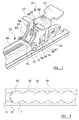
Figure 3 shows a seat support embodying the present invention; -
Figures 4 and 5 show the seat support offigure 3 in an engagement position; -
Figure 6 shows components of a locking mechanism; -
Figure 7 shows a further view of the locking mechanism; -
Figures 8 and9 shows an engagement position of the seat support offigure 3 ; and -
Figure 10 shows an end-on view of the seat support offigure 3 . - Referring initially to
Figure 2 , atrack 11 adapted to be mounted in the floor of a motor vehicle is shown, and this track is the same as that discussed above in relation tofigure 1 . Thetrack 11 preferably comprises an extrusion of an appropriate material, such as steel. Thetrack 11 defines a planar undersurface 12 adapted to be secured to the floor of a vehicle (not shown) and anupper surface 13 which may be substantially flush with the floor of the vehicle. Acentral slot 14 is provided in thetrack 11 which communicates with an under-cutchannel 15. Thetrack 11 thus prevents two inwardly directedlips slot 14. - Each of the inwardly directed
lips alternating protrusions 18 andrecesses 19 along the length of thetrack 11. Theseprotrusions 18 andrecesses 19 will typically have a rounded profile, as shown inFigure 2 , or may have a more square or angular profile, depending upon the application or vehicle being used. Theprotrusions 18 andrecesses 19 on the twolips - The
first protrusions 18 define, as discussed above, shoulder surfaces on each side thereof, and the profile of the shoulder surfaces will depend upon the profile of theprotrusions 18 andrecesses 19. Eachrecess 19 defines a forward-facingshoulder 20 and a rear-facingshoulder 21. - Additionally, the underside of each of the
first protrusions 18 may provide a bearing surface on 22 its inner face. Thebearing surface 22 may extend to the entire surface of the undersides of each of thelips bearing surface 22 will depend upon the application, vehicle ortrack 1 being used. - This type of track has become widely used in vehicles, particularly in passenger vehicles such as coaches or buses.
- A
seat support 23 is shown inFigure 3 . Theseat support 23 is generally elongate, and comprises a robust, elongatemain body 24, which preferably functions as the main structural element of theseat support 23. In the embodiment shown infigure 3 , themain body 24 takes the form of a sturdy, hollow beam with a generally rectangular cross-section. Themain body 24 has atop wall 25, opposingside walls 26 and abottom wall 27. Thebottom wall 27 preferably has aslot 28 running along its length. - An
interface portion 29 is secured to, or formed integrally with, the underside of themain body 24. Theinterface portion 29 comprises, as can be seen infigure 10 (which shows a head-on view of a cross-section through the interface portion 29), a spacingportion 30 which protrudes downwardly from thebottom wall 27 of themain body 24 by a short distance, and a series of spaced-apartprotrusions 31 which extend outwardly from the bottom of the spacingportion 30, generally parallel with thebottom wall 27. The shape and spacing of theprotrusions 31 preferably corresponds exactly or approximately to the shape and spacing of therecesses 19 formed in thelips track 11. In the embodiment shown, therefore, theprotrusions 31 each have a rounded profile. - In the embodiment shown, the
support 23 has twointerface portions 29, a front interface portion 29a which is provided at or near the front of themain body 24, and arear interface portion 29b which is provided at or near the rear of themain body 24. In this embodiment therear interface portion 29b comprisesmore protrusions 31 than the front interface portion 29a, for reasons which will be discussed below. However, other embodiments may have different arrangements, and may comprise a single interface portion running along the underside of all or some of themain body 24. - The
seat support 23 also includes a first bracingportion 32, which is positioned at thefront end 33 of thesupport 23. It is envisaged that the first bracingportion 32 will be fixed with respect to themain body 24, or formed integrally therewith, depending upon the intended application and size of theseat support 23. InFigure 3 , the first bracingportion 32 is integrally formed as part of themain body 24, and is provided at thefront end 33 of themain body 24. In the embodiment shown, theupper wall 25 of themain body 24 has a portion 34 which extends forwardly, and is deflected downwardly (preferably through around 90°) to form the first bracingportion 32. An additional layer of strengtheningmaterial 35 may be provided, and in the embodiment offigure 3 the strengtheningmaterial 35 is bonded to the underside of the first bracingportion 32. - At a
rear end 36 of theseat support 23, alocking mechanism 37 is provided. A view of some features of thelocking mechanism 37 is shown infigure 6 . The design shown infigure 6 is slightly different, in some details, to the design shown in some of the other figures, although these differences are not of any technical significance. Thelocking mechanism 37 comprises amain body 38, which takes the form of a sturdy housing made from a robust material such as steel. Themain body 38 can be seen infigure 3 , and it can be seen that themain body 38 substantially encloses several components of thelocking mechanism 37. Because themain body 38 also obscures components, themain body 38 is shown in "phantom" infigure 6 . - The
main body 38 includes left andright side walls 39, connected to one another by atop wall 40. Thetop wall 40 includes apress lever 41, which may be used to operate the locking mechanism 37 (described in more detail below). In the embodiment shown thepress lever 41 is provided on the rear side of thetop wall 40. Thepress lever 41 may flare upwardly with respect to thetop wall 40. Themain body 38 is preferably generally open on its front side (i.e. the side facing in the forward direction of travel) and its back side. It will therefore be understood that themain body 38 generally takes the form of an inverted "U". - Towards its rear side, the
locking mechanism 37 includes a clampingbody 42. The clampingbody 42 has left andright side walls 43, which are connected by a rear wall 44 (which may extend over all or substantially all of the height of theside walls 43, or only over a part of this height). The left andright side walls 43 of the clampingbody 42 overlap (from a side view) and lie within theside walls 39 of themain body 38. theside walls 43 of the clampingbody 42 havelower edges 45 which are generally flat. - The clamping
body 42 is not connected to themain body 38, but may move in an upwards/downwards direction with respect to themain body 38, i.e. in a direction generally perpendicular to the plane of thetop wall 40 of themain body 38. In the embodiment shown infigure 6 , eachside wall 43 of the clampingbody 42 has a pair ofslots 46 formed therein. Theslots 46 in eachside wall 43 are generally aligned with each other, and extend in a direction that is generally perpendicular to the plane of thetop wall 40 of themain body 38. - A pair of
guide rods 47 extend between, and are fixed with respect to, theside walls 39 of themain body 38. These guiderods 47 each pass through one of theslots 46 in each of theside walls 43 of the clampingbody 42. It will be understood that the clampingbody 42 may therefore move through a limited distance with respect to themain body 38, and that this distance is determined by the length of theslots 46. However, the clampingbody 42 may not be removed from themain body 38. - A
first spring 48 extends between the underside of thetop wall 40 of themain body 38 and the clampingbody 42. Thefirst spring 48 is a compression spring, that biases the clampingbody 42 away from thetop wall 40 of the main body. In preferred embodiments, when thelocking mechanism 37 is in a rest state (i.e. not significantly affected by external forces), the clampingbody 42 rests in a position which is as far from thetop wall 40 of themain body 38 as theslots 46 and guiderods 47 will allow. - Also contained within the
main body 38 is a plunger 49. The plunger 49 generally takes the form of a rod, which is arranged substantially vertically (i.e. substantially perpendicular to thetop wall 40 of the main body 38), and carries at its lower end a second bracingportion 50. - The plunger 49 has guide pins 51 protruding from its sides which face the inner sides of the
side walls 39 of themain body 38. The guide pins 51 are received in vertically-orientedslots 52 formed in theside walls 39. It will therefore be understood that the plunger 49 may move through a limited distance in a vertical direction with respect to themain body 38, and that this distance is determined by the length of theslots 52. - A
second spring 53 is positioned between the underside of thetop wall 40 of themain body 38 and atop surface 54 of the plunger 49. Thesecond spring 53 is a compression spring, which biases the plunger 49 away from thetop wall 40. - The plunger 49 is positioned further forward than the clamping
body 42. Although the plunger 49 and clampingbody 42 are both movable with respect to themain body 38, they are independently movable and are not connected to one another. - The
locking mechanism 37 further comprises alock element 55, which is positioned near the front of themain body 38. Thelock element 55 takes (in this embodiment) the form of parallel, spaced apart plates, each of which takes the same general shape. Only one of the plates can be seen, side-on, infigure 6 . Thelock element 55 comprises afirst portion 56, which is arranged generally vertically, and a top part of thefirst portion 56 protrudes upwardly above thetop wall 40 of themain body 38. The top part of the first portion includeshandles 57 which may be grasped by a user. - A bottom part of the
first portion 56 lies below the level of thetop wall 40 of themain body 38, and has anelongate slot 58 formed therethrough. Theslot 58 is substantially vertical, i.e. substantially perpendicular to thetop wall 40 of themain body 38, and passes through thefirst portion 56 of the lock element in a direction which is perpendicular to the axis of themain body 24 of thesupport 23. Apin 59, which extends between theside walls 39 of themain body 38, passes through theslot 58. The skilled reader will therefore understand that thelock element 55 may move through a limited distance with respect to themain body 38, with this distance being determined by the length of theslot 58. The lock element is constrained to move in a generally vertical direction, i.e. in a direction which is generally perpendicular to the plane of thetop wall 40 of themain body 38 of thelocking mechanism 37. - The
lock element 55 is positioned adjacent the plunger 49 (and, in this example, in front of the plunger 49, i.e. further along in the forward direction of travel). Acatch 60 extends from thelock element 55 towards the plunger 49, and thiscatch 60 is received in acorresponding recess 61 formed in a side of the plunger 49 that faces thelock element 55. Therecess 61 has upward- and downward-facingshoulders recess 61 is, in this example, longer than the catch 60 (in the vertical direction), and so thecatch 60 may move vertically through a short distance within therecess 61. However, beyond this range of motion, thecatch 60 will abut against the upward- or downward-facingshoulder recess 61. - A
second portion 64 of thelock element 55 protrudes generally downwardly from thefirst portion 56. A bearingelement 65 is generally vertically-oriented, and positioned further forward (i.e. further in the forward direction of travel) than thefirst portion 56 of thelock element 55. The bearingelement 65 has a forward-facingbearing surface 66. A supportingstrut 67 connects atop end 68 of the bearingelement 65 to thefirst portion 56. - A
rear support 69 extends downwardly from thefirst portion 56 of thelock element 55, and is oriented generally vertically. Therear support 69 is generally parallel with and spaced apart from the bearingelement 65 in a rearward direction. Anarching connection 70 is formed extending between the bearingelement 65 and therear support 69. Thearching connection 70 forms a downward-facingtrough 71, which extends in a direction generally perpendicular to the longitudinal axis of themain body 24 of thesupport 23. - On the front side of the
main body 38, theside walls 39 extend forwardly at their lower edges and have alignedbores 72 passing therethrough. Thetrough 71 formed by thearching connection 70 is vertically aligned with thebores 72. - The
main body 38 of thelocking mechanism 37 is pivotally connected to a rear end of themain body 24 of thetrack 11. Theside walls 26 of themain body 24 of theseat support 23 terminates at their rear ends in a pair of rearwardly-extendingears 73, which have bores formed therethrough. To connect thelocking mechanism 37 to thesupport 23, abolt 74 passes through both thebores 72 formed in themain body 38 and through the bores formed in the rearwardly-extendingears 73 of thesupport 23. Thus, the rear of thesupport 23 is pivotally connected to the front of thelocking mechanism 37. -
Figure 7 shows thelocking mechanism 37 attached to theseat support 23. It can be seen that themain body 24 of thesupport 23 has arear edge 75, where thetop wall 25 and thebottom wall 27 terminate. Only the rearward-extendingears 73 of theside walls 26 extend rearwardly past thisrear edge 75. - Engagement of the
seat support 23 with atrack 11 will now be described. - In an initial stage, the
seat support 23 is placed onto a track 11 (of the type shown infigure 2 ) in an engagement position, in which theprotrusions 31 of theseat support 23 are aligned with therecesses 19 of thetrack 11. Theprotrusions 31 of theseat support 23 may therefore pass through therecesses 19 of the track, so that theprotrusions 31 of theseat support 23 pass into thechannel 15 of thetrack 11, between theunder surface 12 of thetrack 11 and the undersides of thelips - This engagement position is shown in
figures 4 and 5. Figure 4 shows a side view of theseat support 23 andtrack 11.Figure 5 shows a schematic view of the alignment of theprotrusions 31 of theseat support 23 and theprotrusions 18 and recesses 19 of thetrack 11, as well as the first bracingportion 32. It can be seen that, in the engagement position, the first bracingportion 32 lies near the middle of one of therecesses 19 of thetrack 11, spaced apart from both the forward-facing and rear-facingshoulders - In the engagement position, the
main body 38 of thelocking mechanism 37 is pivoted upwardly away from thetrack 11 into a raised position, in which alower edge 76 of themain body 38 is deflected away from being parallel with themain body 24 of thesupport 23, and lies at an angle thereto. In preferred embodiments, in the raised position thelower edge 76 of themain body 38 of thelocking mechanism 37 may be at an angle of around 30-40° with respect to themain body 24 of thesupport 23. - When the
main body 38 of thelocking mechanism 37 is pivoted upwardly into the raised position, the underside of the bearingelement 65 rests against thetop wall 25 of themain body 24 of thesupport 23. Thesecond spring 53 presses the plunger 49 andlock element 55 away from thetop wall 40 of themain body 38 of thelocking mechanism 37, and biases the bearingelement 65 against thetop wall 25 of themain body 24 of thesupport 23. In this position, thetrough 71 formed by thearching connection 70 is spaced apart from thebores 72 formed through the main body, as is shown infigure 6 . - When the
seat support 23 is placed on thetrack 11 in the engagement position, and themain body 38 of the lockingarrangement 37 is in the raised position, the second bracingportion 50 is raised above the level of theupper surface 13 of thetrack 11. - The
seat support 23 is then slid forwardly with respect to thetrack 11, so that the first bracingportion 32 abuts against a pair of rearward-facingshoulders 8. This is shown schematically infigure 8 . As infigure 5 , the positions of theprotrusions 31 of thesupport 23 are shown in dashed lines, and it can be seen that theprotrusions 31 now align with or overlap with theprotrusions 18 of thetrack 11. It will therefore be understood that, in this position, theseat support 23 cannot be separated from thetrack 11 by lifting theseat support 23 directly upwardly and away from thetrack 11. This is the engagement position of theseat support 23 with respect to thetrack 11. - The user then presses downwardly on the
press lever 41, which tends to rotate themain body 38 of thelocking mechanism 37 downwardly around thebolt 74. As this happens, thelower edges 45 of theside walls 43 of the clampingbody 42 come into contact with theupper surface 13 of thetrack 11, one on either side of thecentral slot 14 formed in thetrack 11. As this occurs, thefirst spring 48 will be compressed, as the clampingbody 42 is pushed towards thetop wall 40 of themain body 38. - As the user presses further on the
press lever 41, themain body 38 of the locking mechanism rotates further, and also thefirst spring 48 is compressed further. As this occurs, the bearingelement 65 slides along thetop wall 25 of themain body 24 of thesupport 23, towards therear edge 75 thereof. When themain body 38 has been rotated so that thelower edge 76 thereof is substantially parallel with themain body 24 of thesupport 23, the bearingelement 65 moves into a position where it no longer presses against thetop wall 25 of themain body 24 of thesupport 23. That is, the bearingelement 65 slides off therear edge 75 of themain body 24 of thesupport 23. At this point, thesecond spring 53 may drive the plunger 49 downwardly to the furthest point of its range of motion. - The second bracing
portion 50, which is positioned on the lower end of the plunger 49, is driven downwardly into thetrack 11. The spacing between the first and second bracingportions portion 32 in the engaged position shown infigure 8 , braced against a pair of rearward-facingshoulders 8, when themain body 38 of thelocking mechanism 37 is pivoted downwardly, the second bracingportion 50 is also braced against a (different) pair of rearward-facingshoulders 8. The skilled reader will therefore understand that the spacing between the edges of the first and second bracingportions shoulders 8 is (when themain body 38 of thelocking mechanism 37 is pivoted downwardly, and when the plunger 49 is driven downwardly, as described above) equal or substantially equal to a multiple of the "pitch" betweenadjacent apertures 19 of thetrack 11. - As the
second spring 53 drives the plunger 49 downwards, therefore, this drives the second bracingportion 51 into one of theapertures 19 in thetrack 11, so that the second bracingportion 50 bears against a pair of rearward-facingshoulders 8 in the track. - As the
second spring 53 drives the plunger 49 downwards, the downward-facingshoulder 63 in therecess 61 of the plunger engages thecatch 60 of thelock element 55, and thelock element 55 is also driven downwardly. As this occurs, the bearingelement 65 of thelock element 55 is driven into a position in which its forward-facingbearing surface 66 bears against therear edge 75 of themain body 24 of thesupport 23. Thetrough 70 also comes to rest against thebolt 74 about which thelocking mechanism 37 pivots with respect to themain body 24 of thesupport 23. - At this stage, the
seat support 23 is in the position shown infigure 9 . The first and second bracingelements shoulders 8 in thetrack 11. This robustly prevents theseat support 23 from moving forwardly with respect to thetrack 11. - The clamping
body 42 is driven firmly against thetop surface 13 of thetrack 11, by the action of thefirst spring 48. This tends to lift thelocking mechanism 37 upwardly with respect to thetrack 11. As it does so, it also lifts upwardly themain body 24 of thesupport 23, and pulls theprotrusions 19 of thesupport 23 into firm engagement with theundersides 22 of thelips lips track 11 are effectively clamped between theprotrusions 19 of the support 23 (on their undersides 22) and thelower edges 45 of theside walls 43 of the clamping body 42 (on their top sides 13). This clamping action is driven by thefirst spring 48. The clamping action holds theseat support 23 firmly in place with respect to thetrack 11, reducing or eliminating any movement, vibration or "play" between theseat support 23 and thetrack 11. The clamping action will also strongly resist any rearward motion of theseat support 23 with respect to thetrack 11. - When in this position, the
main body 38 of thelocking mechanism 37 cannot rotate upwardly, because thebearing element 65 of thelock element 55 abuts against therear edge 75 of themain body 24 of thesupport 23. Thelock element 55 is held in place by the action of thesecond spring 53, and so it will not be dislodged by jolting or vibration. Thelock element 55, and in particular the bearingelement 65 thereof, therefore act as a catch to retain thelocking mechanism 37 in a locked configuration. - It will therefore be understood that, in this locked configuration, the
seat support 23 is held firmly in place with respect to thetrack 11, and will strongly resist forward, rearward or upward (i.e. lifting) movement of any kind with respect to thetrack 11. - In order to remove the
seat support 23 from thetrack 11, the user may grasp thehandle 57 on theupper portion 56 of thelock element 55, and lift thelock element 55 upwardly. This will lift up the bearingelement 65 above the level of thetop wall 25 of themain body 24 of the seat support 23 (and will also withdraw thesecond bearing element 50 from the track 11). Themain body 38 of the locking element can then be rotated upwardly away from thetrack 11, until it is once more in the raised position. Theseat support 23 may then be moved rearwardly with respect to thetrack 11, until it is in the engagement position, shown infigures 4 and 5 . Theseat support 23 may then simply be lifted upwardly away from thetrack 11. - In alternative embodiments, the seat support may have first and second bracing elements which are fixed in place with respect to the main body of the support, and a clamping arrangement which clamps the seat support against the track without involving any movement of either of the bracing elements. For instance, the locking mechanism of the embodiment shown in the figures could omit the plunger 49, but still include the clamping body 42 (biased by the first spring 48) and the lock element 55 (biased by the second spring 53). However, the second bracing element could simply be an element which is fixed to the main body of the support. To install the support, the support could be placed on the track so that both support elements are received in
respective apertures 19 of thetrack 11, and the support may then be slid forward until both bracing elements bear against respective rearward-facingshoulders 8 of thetrack 11. The locking mechanism may then be activated to clamp the support to thetrack 11, with the clampingbody 42 pressing downward on theupper surface 13 of thetrack 11, and the bearingelement 65 of thelock element 55 abutting against therear edge 75 of the main body and thus preventing the main body of the locking arrangement from pivoting upwardly. - Any other kind of clamping or locking mechanism may be used to secure the seat support to the track, and the invention is not limited to the mechanisms described above. In general, it is preferred that one or more of the
lips track 11 are gripped between two elements, so that one element presses against the top side of the lip(s) and another element presses against the bottom side of the lip(s). - The skilled reader will understand that the embodiments described above provide simple and robust arrangements for securing a support to a track. In particular, even if used by an unfamiliar operator, a support embodying the invention should have a high level of safety and a low failure rate in the event of a head-on collision.
- When used in this specification and claims, the terms "comprises" and "comprising" and variations thereof mean that the specified features, steps or integers are included. The terms are not to be interpreted to exclude the presence of other features, steps or components.
- The features disclosed in the foregoing description, or the following claims, or the accompanying drawings, expressed in their specific forms or in terms of a means for performing the disclosed function, or a method or process for attaining the disclosed result, as appropriate, may, separately, or in any combination of such features, be utilised for realising the invention in diverse forms thereof.
Claims (15)
- A seat support for use with a vehicle seat and adapted to engage a track provided on the floor of a vehicle, the track comprising two inwardly-directed lips on opposed sides of a slot, the lips providing first alternating protrusions and recesses along the length of the track, the protrusions being spaced apart by a spacing distance, the first and second protrusions defining shoulder surfaces on each side thereof,
the seat support having an elongate main body and comprising:an interface portion which has a profile comprising second alternating protrusions and recesses, the protrusions being spaced apart by the same spacing distance;first and second bracing members; anda locking arrangement, wherein:the seat support is configured such that the second protrusions may be aligned with the first recesses so that the interface portion may be placed within the slot in an engagement position, the seat support being moveable with respect to the slot, from the engagement position into a bracing position in which the first and second protrusions are substantially aligned, preventing the interface portion from being removed from the slot;the first bracing member is substantially fixed in place with respect to the main body of the seat support, so that in both the engagement position and the bracing position the first bracing member is received in one of the recesses of the track;the locking arrangement is movable between a release configuration and a locking configuration, wherein in the release configuration the locking arrangement allows longitudinal movement of the seat support with respect to the track, and in the locking configuration the locking arrangement exerts a clamping force on a part of the track, to lock the seat support in place longitudinally with respect to the track; andwhen the seat support is in the engagement position and the locking arrangement is in the locking configuration, the first and second bracing members are received in respective recesses of the track and are braced against respective first and second pairs of shoulders on the track, wherein the first and second pairs of shoulders face in substantially the same direction. - A seat support according to claim 1 wherein:the track defines a first longitudinal direction and a second substantially opposite longitudinal direction;the first and second pairs of shoulders face in the second direction; andin the bracing position, the bracing of the first and second bracing members against the first and second pairs of shoulders prevents longitudinal movement of the seat support with respect to the track in the first direction.
- A seat support according to claim 1 or 2, wherein the locking arrangement comprises a first clamping member which, in the locking configuration, is biased against an upper surface of the track.
- A seat support according to claim 3, further comprising an operating member which a user may operate to drive the first clamping member against the upper surface of the track.
- A seat support according to any preceding claim wherein, when the locking arrangement is in the locking configuration, at least one protrusion of the interface portion is pressed against the underside of at least one of the lips of the track.
- A seat support according to any one preceding claim, further comprising a catch arrangement to retain the locking arrangement in the locking configuration, and preferably wherein the catch arrangement comprises a catch element which, in a retaining position, bears against a further part of the seat support to prevent the locking arrangement from moving from the locking configuration to the release configuration, more preferably wherein, when the locking arrangement is moved from the release configuration to the locking configuration, the catch member moves automatically into the retaining position, and yet more preferably wherein the seat support comprises a handle which a user may grasp to move the catch element out of the retaining position, so that the locking arrangement can be moved from the locking configuration to the release configuration.
- A seat support according to any one preceding claim, wherein the second bracing member is provided on, or carried by, part of the locking arrangement, or wherein the second bracing member is movable between an extended position and a retracted position, and preferably wherein the second bracing member is biased into the extended position.
- A seat support according to any one of claims 7, when dependent upon claim 6, wherein the catch element is connected to, or moves together with, the second bracing member, and preferably wherein, when the catch member is in the retaining position, the second bracing member is in the extended position.
- A seat support according to any preceding claim, wherein the first and/or second protrusions have a rounded profile, or wherein the first and/or second bracing members comprise a surface against which the respective first and/or second pair of shoulders may bear.
- A seat support according to claim 7 or 9, wherein the second bracing member is substantially fixed in place with respect to the main body of the seat support.
- A seat support according to any preceding claim wherein, when the seat support is placed on the track in the engagement position and then moved longitudinally with respect to the track, the first bracing portion contacts a pair of shoulders of the track and acts as a stop, so that the seat support is in the bracing position.
- A seat support according to any preceding claim wherein when the seat support is in the bracing position, the first and second recesses overlap, and preferably wherein when the seat support is in the locking position, the first and second recesses are generally aligned.
- A seat support according to any preceding claim, wherein the track is installed in a vehicle which has a normal forward direction of travel, and the track comprises forward-facing shoulders and rearward-facing shoulders, and wherein, in the bracing position, both the first and second bracing elements are braced against respective pairs of rearward-facing shoulders.
- A seat support according to any previous claim in combination with a track which comprises:two inwardly-directed lips on opposed sides of a slot, the lips providing first alternating protrusions and recesses along the length of the track, the protrusions being spaced apart by a spacing distance, the first and second protrusions defining shoulder surfaces on each side thereof.
- A seat including a seat support in accordance with any previous claim.
Applications Claiming Priority (2)
| Application Number | Priority Date | Filing Date | Title |
|---|---|---|---|
| GBGB1509451.9A GB201509451D0 (en) | 2015-06-01 | 2015-06-01 | Adaptable vehicle seat fitting |
| GB1509477.4A GB2538981A (en) | 2015-06-01 | 2015-06-02 | Adapable vehicle seat fitting |
Publications (1)
| Publication Number | Publication Date |
|---|---|
| EP3100901A1 true EP3100901A1 (en) | 2016-12-07 |
Family
ID=53677574
Family Applications (1)
| Application Number | Title | Priority Date | Filing Date |
|---|---|---|---|
| EP16171615.4A Withdrawn EP3100901A1 (en) | 2015-06-01 | 2016-05-27 | Adaptable vehicle seat anchorage |
Country Status (5)
| Country | Link |
|---|---|
| US (1) | US9878639B2 (en) |
| EP (1) | EP3100901A1 (en) |
| AU (1) | AU2016203533A1 (en) |
| CA (1) | CA2930943A1 (en) |
| GB (2) | GB201509451D0 (en) |
Cited By (2)
| Publication number | Priority date | Publication date | Assignee | Title |
|---|---|---|---|---|
| WO2020039194A1 (en) * | 2018-08-22 | 2020-02-27 | Nmi Safety Systems Limited | Adaptable vehicle seat fitting |
| EP4011775A1 (en) * | 2020-12-10 | 2022-06-15 | VBI Minibus & Components APS | Adjustable passenger seating arrangement |
Families Citing this family (6)
| Publication number | Priority date | Publication date | Assignee | Title |
|---|---|---|---|---|
| US11214374B2 (en) * | 2016-08-01 | 2022-01-04 | Gulfstream Aerospace Corporation | Seat track assemblies for vibration isolation of floor mounted components |
| US10518887B2 (en) * | 2017-06-29 | 2019-12-31 | The Boeing Company | Rotationally-engaged quick installation track fitting |
| CN107599897B (en) * | 2017-09-12 | 2024-02-23 | 福建省华银铝业有限公司 | Seat track for vehicle |
| US10625867B2 (en) * | 2017-10-05 | 2020-04-21 | Fenton Mobility Products, Inc. | Integrable seat leg |
| US10829225B2 (en) * | 2018-12-11 | 2020-11-10 | Ami Industries, Inc. | Track fitting with quick release lock for aircraft seating |
| WO2022075968A1 (en) * | 2020-10-05 | 2022-04-14 | Safran Seats Usa Llc | Seat track stud with roll freedom |
Citations (4)
| Publication number | Priority date | Publication date | Assignee | Title |
|---|---|---|---|---|
| DE19851392A1 (en) * | 1997-11-10 | 1999-05-12 | Jungfalk Ancra Gmbh | Device for temporary connection of motor vehicle's seat to retaining rail |
| US6299230B1 (en) * | 1997-07-10 | 2001-10-09 | Heinrich Oettl | Device for securing quick-release, displaceable and quick-locking motor vehicle equipment |
| US20070253762A1 (en) * | 2006-03-31 | 2007-11-01 | The Boeing Company | Apparatus and methods for removably securing payloads in an aircraft |
| GB2517149A (en) * | 2013-08-12 | 2015-02-18 | Nmi Safety Systems Ltd | Adaptable vehicle seat fitting |
Family Cites Families (11)
| Publication number | Priority date | Publication date | Assignee | Title |
|---|---|---|---|---|
| FR2729898B1 (en) | 1995-01-30 | 1997-04-04 | Faure Bertrand Equipements Sa | IMPROVEMENTS TO SLIDES FOR VEHICLE SEATS AND TO SEATS EQUIPPED WITH SUCH SLIDES |
| GB2347619B (en) | 1999-03-10 | 2002-11-13 | Nmi Safety Systems Ltd | Improvements in or relating to a seat support |
| ATE482879T1 (en) * | 2007-03-22 | 2010-10-15 | Allsafe Jungfalk Gmbh & Co Kg | DEVICE FOR DETERMINING OBJECTS |
| DE602007004320D1 (en) * | 2007-07-27 | 2010-03-04 | Bishop Gmbh Aeronautical Engin | Aircraft seat rail |
| US8528860B2 (en) * | 2008-10-22 | 2013-09-10 | Be Aerospace, Inc. | Tool-less track fastener |
| WO2010097408A2 (en) | 2009-02-24 | 2010-09-02 | Brose Fahrzeugteile Gmbh & Co. Kg, Coburg | Motor vehicle seat |
| GB2477099B (en) * | 2010-01-20 | 2016-01-20 | Unwin C N Ltd | Anchorage Devices |
| GB2477100B (en) | 2010-01-20 | 2016-02-03 | Unwin C N Ltd | Anchorage systems and devices |
| WO2012100152A1 (en) * | 2011-01-20 | 2012-07-26 | Weber Aircraft Llc | Seat track fitting |
| FR2975642B1 (en) * | 2011-05-27 | 2014-08-22 | Productions B V | FLOATING SEAT ANCHORING SYSTEM |
| DE202011108804U1 (en) | 2011-12-08 | 2012-01-27 | Walter Michler | fastening device |
-
2015
- 2015-06-01 GB GBGB1509451.9A patent/GB201509451D0/en not_active Ceased
- 2015-06-02 GB GB1509477.4A patent/GB2538981A/en not_active Withdrawn
-
2016
- 2016-05-25 CA CA2930943A patent/CA2930943A1/en not_active Abandoned
- 2016-05-27 EP EP16171615.4A patent/EP3100901A1/en not_active Withdrawn
- 2016-05-27 AU AU2016203533A patent/AU2016203533A1/en not_active Abandoned
- 2016-05-31 US US15/168,577 patent/US9878639B2/en not_active Expired - Fee Related
Patent Citations (4)
| Publication number | Priority date | Publication date | Assignee | Title |
|---|---|---|---|---|
| US6299230B1 (en) * | 1997-07-10 | 2001-10-09 | Heinrich Oettl | Device for securing quick-release, displaceable and quick-locking motor vehicle equipment |
| DE19851392A1 (en) * | 1997-11-10 | 1999-05-12 | Jungfalk Ancra Gmbh | Device for temporary connection of motor vehicle's seat to retaining rail |
| US20070253762A1 (en) * | 2006-03-31 | 2007-11-01 | The Boeing Company | Apparatus and methods for removably securing payloads in an aircraft |
| GB2517149A (en) * | 2013-08-12 | 2015-02-18 | Nmi Safety Systems Ltd | Adaptable vehicle seat fitting |
Cited By (2)
| Publication number | Priority date | Publication date | Assignee | Title |
|---|---|---|---|---|
| WO2020039194A1 (en) * | 2018-08-22 | 2020-02-27 | Nmi Safety Systems Limited | Adaptable vehicle seat fitting |
| EP4011775A1 (en) * | 2020-12-10 | 2022-06-15 | VBI Minibus & Components APS | Adjustable passenger seating arrangement |
Also Published As
| Publication number | Publication date |
|---|---|
| GB201509451D0 (en) | 2015-07-15 |
| GB201509477D0 (en) | 2015-07-15 |
| CA2930943A1 (en) | 2016-12-01 |
| US9878639B2 (en) | 2018-01-30 |
| US20160347208A1 (en) | 2016-12-01 |
| AU2016203533A1 (en) | 2016-12-15 |
| GB2538981A (en) | 2016-12-07 |
Similar Documents
| Publication | Publication Date | Title |
|---|---|---|
| EP3100901A1 (en) | Adaptable vehicle seat anchorage | |
| DE60121282T2 (en) | Child seat | |
| EP1839938B1 (en) | Seat structure for vehicle | |
| US9758062B2 (en) | Rail for a vehicle seat and vehicle seat comprising such a rail | |
| CN105313728B (en) | child seat | |
| EP2837526A1 (en) | Adaptable vehicle seat fitting | |
| CN108749664B (en) | Child safety seat with steel skeleton structure and application method thereof | |
| KR20120082740A (en) | Seat rail locking device of vehicle seat | |
| EP3840982B1 (en) | Adaptable vehicle seat fitting | |
| KR20190016836A (en) | Seat Device For Wheelchair | |
| CN108290509A (en) | Seat depth adjustment | |
| AU2020206600B2 (en) | Seating furniture chassis | |
| US6357715B1 (en) | Support for a vehicle seat | |
| CN205395837U (en) | Children's safety seat and ISOFIX coupling assembling thereof | |
| CN112158110B (en) | Child seat | |
| CN202294355U (en) | Sliding rail locking mechanism for automobile | |
| CN110843615B (en) | Easy-access unlocking mechanism for automobile seat | |
| CA2770422C (en) | Seat connector and method of using said seat connector | |
| CN103775447A (en) | Press locking structure and automobile with press locking structure | |
| CN214215556U (en) | Adjust handle subassembly and car | |
| KR20180138015A (en) | Seat extension structure | |
| JP6575182B2 (en) | Vehicle seat | |
| KR101413966B1 (en) | Slide type Headrest for Motor Vehicle | |
| JP2005324947A (en) | Fork rattling preventive device | |
| JP2019051879A (en) | Seat slide device |
Legal Events
| Date | Code | Title | Description |
|---|---|---|---|
| PUAI | Public reference made under article 153(3) epc to a published international application that has entered the european phase |
Free format text: ORIGINAL CODE: 0009012 |
|
| AK | Designated contracting states |
Kind code of ref document: A1 Designated state(s): AL AT BE BG CH CY CZ DE DK EE ES FI FR GB GR HR HU IE IS IT LI LT LU LV MC MK MT NL NO PL PT RO RS SE SI SK SM TR |
|
| AX | Request for extension of the european patent |
Extension state: BA ME |
|
| 17P | Request for examination filed |
Effective date: 20170607 |
|
| RBV | Designated contracting states (corrected) |
Designated state(s): AL AT BE BG CH CY CZ DE DK EE ES FI FR GB GR HR HU IE IS IT LI LT LU LV MC MK MT NL NO PL PT RO RS SE SI SK SM TR |
|
| RIC1 | Information provided on ipc code assigned before grant |
Ipc: B60N 2/07 20060101AFI20180314BHEP Ipc: B60N 2/08 20060101ALI20180314BHEP Ipc: B60N 2/015 20060101ALI20180314BHEP |
|
| GRAP | Despatch of communication of intention to grant a patent |
Free format text: ORIGINAL CODE: EPIDOSNIGR1 |
|
| INTG | Intention to grant announced |
Effective date: 20180420 |
|
| RAP1 | Party data changed (applicant data changed or rights of an application transferred) |
Owner name: NMI SAFETY SYSTEMS LTD. |
|
| STAA | Information on the status of an ep patent application or granted ep patent |
Free format text: STATUS: THE APPLICATION IS DEEMED TO BE WITHDRAWN |
|
| 18D | Application deemed to be withdrawn |
Effective date: 20180831 |