EP3100896A1 - In-wheel motor drive device - Google Patents
In-wheel motor drive device Download PDFInfo
- Publication number
- EP3100896A1 EP3100896A1 EP15742776.6A EP15742776A EP3100896A1 EP 3100896 A1 EP3100896 A1 EP 3100896A1 EP 15742776 A EP15742776 A EP 15742776A EP 3100896 A1 EP3100896 A1 EP 3100896A1
- Authority
- EP
- European Patent Office
- Prior art keywords
- motor
- temperature sensor
- lubricating oil
- electric motor
- speed reducer
- Prior art date
- Legal status (The legal status is an assumption and is not a legal conclusion. Google has not performed a legal analysis and makes no representation as to the accuracy of the status listed.)
- Granted
Links
- 239000003921 oil Substances 0.000 claims abstract description 110
- 239000010687 lubricating oil Substances 0.000 claims abstract description 92
- 239000003638 chemical reducing agent Substances 0.000 claims abstract description 89
- 230000005856 abnormality Effects 0.000 abstract description 26
- 230000033001 locomotion Effects 0.000 description 8
- 238000010586 diagram Methods 0.000 description 7
- RYGMFSIKBFXOCR-UHFFFAOYSA-N Copper Chemical compound [Cu] RYGMFSIKBFXOCR-UHFFFAOYSA-N 0.000 description 6
- 229910052802 copper Inorganic materials 0.000 description 6
- 239000010949 copper Substances 0.000 description 6
- 238000001514 detection method Methods 0.000 description 6
- 238000004088 simulation Methods 0.000 description 6
- 238000004891 communication Methods 0.000 description 5
- 238000002474 experimental method Methods 0.000 description 5
- 238000005096 rolling process Methods 0.000 description 4
- 238000001816 cooling Methods 0.000 description 3
- 230000002093 peripheral effect Effects 0.000 description 3
- 230000000694 effects Effects 0.000 description 2
- 230000005484 gravity Effects 0.000 description 2
- 230000020169 heat generation Effects 0.000 description 2
- 238000005304 joining Methods 0.000 description 2
- 230000001050 lubricating effect Effects 0.000 description 2
- 238000012986 modification Methods 0.000 description 2
- 230000004048 modification Effects 0.000 description 2
- 239000004065 semiconductor Substances 0.000 description 2
- 238000003860 storage Methods 0.000 description 2
- 230000001133 acceleration Effects 0.000 description 1
- 238000010420 art technique Methods 0.000 description 1
- 230000005540 biological transmission Effects 0.000 description 1
- 238000010276 construction Methods 0.000 description 1
- 238000009413 insulation Methods 0.000 description 1
- 238000005461 lubrication Methods 0.000 description 1
- 239000000463 material Substances 0.000 description 1
- 238000000034 method Methods 0.000 description 1
- 239000011347 resin Substances 0.000 description 1
- 229920005989 resin Polymers 0.000 description 1
- 239000000725 suspension Substances 0.000 description 1
- 230000001360 synchronised effect Effects 0.000 description 1
- 238000012360 testing method Methods 0.000 description 1
Images
Classifications
-
- B—PERFORMING OPERATIONS; TRANSPORTING
- B60—VEHICLES IN GENERAL
- B60L—PROPULSION OF ELECTRICALLY-PROPELLED VEHICLES; SUPPLYING ELECTRIC POWER FOR AUXILIARY EQUIPMENT OF ELECTRICALLY-PROPELLED VEHICLES; ELECTRODYNAMIC BRAKE SYSTEMS FOR VEHICLES IN GENERAL; MAGNETIC SUSPENSION OR LEVITATION FOR VEHICLES; MONITORING OPERATING VARIABLES OF ELECTRICALLY-PROPELLED VEHICLES; ELECTRIC SAFETY DEVICES FOR ELECTRICALLY-PROPELLED VEHICLES
- B60L3/00—Electric devices on electrically-propelled vehicles for safety purposes; Monitoring operating variables, e.g. speed, deceleration or energy consumption
- B60L3/0023—Detecting, eliminating, remedying or compensating for drive train abnormalities, e.g. failures within the drive train
- B60L3/0061—Detecting, eliminating, remedying or compensating for drive train abnormalities, e.g. failures within the drive train relating to electrical machines
-
- B—PERFORMING OPERATIONS; TRANSPORTING
- B60—VEHICLES IN GENERAL
- B60K—ARRANGEMENT OR MOUNTING OF PROPULSION UNITS OR OF TRANSMISSIONS IN VEHICLES; ARRANGEMENT OR MOUNTING OF PLURAL DIVERSE PRIME-MOVERS IN VEHICLES; AUXILIARY DRIVES FOR VEHICLES; INSTRUMENTATION OR DASHBOARDS FOR VEHICLES; ARRANGEMENTS IN CONNECTION WITH COOLING, AIR INTAKE, GAS EXHAUST OR FUEL SUPPLY OF PROPULSION UNITS IN VEHICLES
- B60K17/00—Arrangement or mounting of transmissions in vehicles
- B60K17/04—Arrangement or mounting of transmissions in vehicles characterised by arrangement, location or kind of gearing
- B60K17/043—Transmission unit disposed in on near the vehicle wheel, or between the differential gear unit and the wheel
-
- B—PERFORMING OPERATIONS; TRANSPORTING
- B60—VEHICLES IN GENERAL
- B60K—ARRANGEMENT OR MOUNTING OF PROPULSION UNITS OR OF TRANSMISSIONS IN VEHICLES; ARRANGEMENT OR MOUNTING OF PLURAL DIVERSE PRIME-MOVERS IN VEHICLES; AUXILIARY DRIVES FOR VEHICLES; INSTRUMENTATION OR DASHBOARDS FOR VEHICLES; ARRANGEMENTS IN CONNECTION WITH COOLING, AIR INTAKE, GAS EXHAUST OR FUEL SUPPLY OF PROPULSION UNITS IN VEHICLES
- B60K7/00—Disposition of motor in, or adjacent to, traction wheel
- B60K7/0007—Disposition of motor in, or adjacent to, traction wheel the motor being electric
-
- B—PERFORMING OPERATIONS; TRANSPORTING
- B60—VEHICLES IN GENERAL
- B60L—PROPULSION OF ELECTRICALLY-PROPELLED VEHICLES; SUPPLYING ELECTRIC POWER FOR AUXILIARY EQUIPMENT OF ELECTRICALLY-PROPELLED VEHICLES; ELECTRODYNAMIC BRAKE SYSTEMS FOR VEHICLES IN GENERAL; MAGNETIC SUSPENSION OR LEVITATION FOR VEHICLES; MONITORING OPERATING VARIABLES OF ELECTRICALLY-PROPELLED VEHICLES; ELECTRIC SAFETY DEVICES FOR ELECTRICALLY-PROPELLED VEHICLES
- B60L15/00—Methods, circuits, or devices for controlling the traction-motor speed of electrically-propelled vehicles
-
- B—PERFORMING OPERATIONS; TRANSPORTING
- B60—VEHICLES IN GENERAL
- B60L—PROPULSION OF ELECTRICALLY-PROPELLED VEHICLES; SUPPLYING ELECTRIC POWER FOR AUXILIARY EQUIPMENT OF ELECTRICALLY-PROPELLED VEHICLES; ELECTRODYNAMIC BRAKE SYSTEMS FOR VEHICLES IN GENERAL; MAGNETIC SUSPENSION OR LEVITATION FOR VEHICLES; MONITORING OPERATING VARIABLES OF ELECTRICALLY-PROPELLED VEHICLES; ELECTRIC SAFETY DEVICES FOR ELECTRICALLY-PROPELLED VEHICLES
- B60L15/00—Methods, circuits, or devices for controlling the traction-motor speed of electrically-propelled vehicles
- B60L15/02—Methods, circuits, or devices for controlling the traction-motor speed of electrically-propelled vehicles characterised by the form of the current used in the control circuit
- B60L15/025—Methods, circuits, or devices for controlling the traction-motor speed of electrically-propelled vehicles characterised by the form of the current used in the control circuit using field orientation; Vector control; Direct Torque Control [DTC]
-
- B—PERFORMING OPERATIONS; TRANSPORTING
- B60—VEHICLES IN GENERAL
- B60L—PROPULSION OF ELECTRICALLY-PROPELLED VEHICLES; SUPPLYING ELECTRIC POWER FOR AUXILIARY EQUIPMENT OF ELECTRICALLY-PROPELLED VEHICLES; ELECTRODYNAMIC BRAKE SYSTEMS FOR VEHICLES IN GENERAL; MAGNETIC SUSPENSION OR LEVITATION FOR VEHICLES; MONITORING OPERATING VARIABLES OF ELECTRICALLY-PROPELLED VEHICLES; ELECTRIC SAFETY DEVICES FOR ELECTRICALLY-PROPELLED VEHICLES
- B60L15/00—Methods, circuits, or devices for controlling the traction-motor speed of electrically-propelled vehicles
- B60L15/20—Methods, circuits, or devices for controlling the traction-motor speed of electrically-propelled vehicles for control of the vehicle or its driving motor to achieve a desired performance, e.g. speed, torque, programmed variation of speed
- B60L15/2054—Methods, circuits, or devices for controlling the traction-motor speed of electrically-propelled vehicles for control of the vehicle or its driving motor to achieve a desired performance, e.g. speed, torque, programmed variation of speed by controlling transmissions or clutches
-
- B—PERFORMING OPERATIONS; TRANSPORTING
- B60—VEHICLES IN GENERAL
- B60L—PROPULSION OF ELECTRICALLY-PROPELLED VEHICLES; SUPPLYING ELECTRIC POWER FOR AUXILIARY EQUIPMENT OF ELECTRICALLY-PROPELLED VEHICLES; ELECTRODYNAMIC BRAKE SYSTEMS FOR VEHICLES IN GENERAL; MAGNETIC SUSPENSION OR LEVITATION FOR VEHICLES; MONITORING OPERATING VARIABLES OF ELECTRICALLY-PROPELLED VEHICLES; ELECTRIC SAFETY DEVICES FOR ELECTRICALLY-PROPELLED VEHICLES
- B60L3/00—Electric devices on electrically-propelled vehicles for safety purposes; Monitoring operating variables, e.g. speed, deceleration or energy consumption
- B60L3/04—Cutting off the power supply under fault conditions
-
- B—PERFORMING OPERATIONS; TRANSPORTING
- B60—VEHICLES IN GENERAL
- B60L—PROPULSION OF ELECTRICALLY-PROPELLED VEHICLES; SUPPLYING ELECTRIC POWER FOR AUXILIARY EQUIPMENT OF ELECTRICALLY-PROPELLED VEHICLES; ELECTRODYNAMIC BRAKE SYSTEMS FOR VEHICLES IN GENERAL; MAGNETIC SUSPENSION OR LEVITATION FOR VEHICLES; MONITORING OPERATING VARIABLES OF ELECTRICALLY-PROPELLED VEHICLES; ELECTRIC SAFETY DEVICES FOR ELECTRICALLY-PROPELLED VEHICLES
- B60L50/00—Electric propulsion with power supplied within the vehicle
- B60L50/50—Electric propulsion with power supplied within the vehicle using propulsion power supplied by batteries or fuel cells
- B60L50/51—Electric propulsion with power supplied within the vehicle using propulsion power supplied by batteries or fuel cells characterised by AC-motors
-
- H—ELECTRICITY
- H02—GENERATION; CONVERSION OR DISTRIBUTION OF ELECTRIC POWER
- H02K—DYNAMO-ELECTRIC MACHINES
- H02K11/00—Structural association of dynamo-electric machines with electric components or with devices for shielding, monitoring or protection
- H02K11/20—Structural association of dynamo-electric machines with electric components or with devices for shielding, monitoring or protection for measuring, monitoring, testing, protecting or switching
- H02K11/25—Devices for sensing temperature, or actuated thereby
-
- H—ELECTRICITY
- H02—GENERATION; CONVERSION OR DISTRIBUTION OF ELECTRIC POWER
- H02K—DYNAMO-ELECTRIC MACHINES
- H02K17/00—Asynchronous induction motors; Asynchronous induction generators
- H02K17/02—Asynchronous induction motors
- H02K17/12—Asynchronous induction motors for multi-phase current
-
- H—ELECTRICITY
- H02—GENERATION; CONVERSION OR DISTRIBUTION OF ELECTRIC POWER
- H02K—DYNAMO-ELECTRIC MACHINES
- H02K7/00—Arrangements for handling mechanical energy structurally associated with dynamo-electric machines, e.g. structural association with mechanical driving motors or auxiliary dynamo-electric machines
- H02K7/10—Structural association with clutches, brakes, gears, pulleys or mechanical starters
- H02K7/116—Structural association with clutches, brakes, gears, pulleys or mechanical starters with gears
-
- H—ELECTRICITY
- H02—GENERATION; CONVERSION OR DISTRIBUTION OF ELECTRIC POWER
- H02K—DYNAMO-ELECTRIC MACHINES
- H02K9/00—Arrangements for cooling or ventilating
- H02K9/19—Arrangements for cooling or ventilating for machines with closed casing and closed-circuit cooling using a liquid cooling medium, e.g. oil
-
- H—ELECTRICITY
- H02—GENERATION; CONVERSION OR DISTRIBUTION OF ELECTRIC POWER
- H02P—CONTROL OR REGULATION OF ELECTRIC MOTORS, ELECTRIC GENERATORS OR DYNAMO-ELECTRIC CONVERTERS; CONTROLLING TRANSFORMERS, REACTORS OR CHOKE COILS
- H02P29/00—Arrangements for regulating or controlling electric motors, appropriate for both AC and DC motors
- H02P29/60—Controlling or determining the temperature of the motor or of the drive
- H02P29/64—Controlling or determining the temperature of the winding
-
- H—ELECTRICITY
- H02—GENERATION; CONVERSION OR DISTRIBUTION OF ELECTRIC POWER
- H02P—CONTROL OR REGULATION OF ELECTRIC MOTORS, ELECTRIC GENERATORS OR DYNAMO-ELECTRIC CONVERTERS; CONTROLLING TRANSFORMERS, REACTORS OR CHOKE COILS
- H02P29/00—Arrangements for regulating or controlling electric motors, appropriate for both AC and DC motors
- H02P29/60—Controlling or determining the temperature of the motor or of the drive
- H02P29/68—Controlling or determining the temperature of the motor or of the drive based on the temperature of a drive component or a semiconductor component
-
- B—PERFORMING OPERATIONS; TRANSPORTING
- B60—VEHICLES IN GENERAL
- B60K—ARRANGEMENT OR MOUNTING OF PROPULSION UNITS OR OF TRANSMISSIONS IN VEHICLES; ARRANGEMENT OR MOUNTING OF PLURAL DIVERSE PRIME-MOVERS IN VEHICLES; AUXILIARY DRIVES FOR VEHICLES; INSTRUMENTATION OR DASHBOARDS FOR VEHICLES; ARRANGEMENTS IN CONNECTION WITH COOLING, AIR INTAKE, GAS EXHAUST OR FUEL SUPPLY OF PROPULSION UNITS IN VEHICLES
- B60K17/00—Arrangement or mounting of transmissions in vehicles
- B60K17/04—Arrangement or mounting of transmissions in vehicles characterised by arrangement, location or kind of gearing
- B60K17/043—Transmission unit disposed in on near the vehicle wheel, or between the differential gear unit and the wheel
- B60K17/046—Transmission unit disposed in on near the vehicle wheel, or between the differential gear unit and the wheel with planetary gearing having orbital motion
-
- B—PERFORMING OPERATIONS; TRANSPORTING
- B60—VEHICLES IN GENERAL
- B60K—ARRANGEMENT OR MOUNTING OF PROPULSION UNITS OR OF TRANSMISSIONS IN VEHICLES; ARRANGEMENT OR MOUNTING OF PLURAL DIVERSE PRIME-MOVERS IN VEHICLES; AUXILIARY DRIVES FOR VEHICLES; INSTRUMENTATION OR DASHBOARDS FOR VEHICLES; ARRANGEMENTS IN CONNECTION WITH COOLING, AIR INTAKE, GAS EXHAUST OR FUEL SUPPLY OF PROPULSION UNITS IN VEHICLES
- B60K7/00—Disposition of motor in, or adjacent to, traction wheel
- B60K2007/0038—Disposition of motor in, or adjacent to, traction wheel the motor moving together with the wheel axle
-
- B—PERFORMING OPERATIONS; TRANSPORTING
- B60—VEHICLES IN GENERAL
- B60K—ARRANGEMENT OR MOUNTING OF PROPULSION UNITS OR OF TRANSMISSIONS IN VEHICLES; ARRANGEMENT OR MOUNTING OF PLURAL DIVERSE PRIME-MOVERS IN VEHICLES; AUXILIARY DRIVES FOR VEHICLES; INSTRUMENTATION OR DASHBOARDS FOR VEHICLES; ARRANGEMENTS IN CONNECTION WITH COOLING, AIR INTAKE, GAS EXHAUST OR FUEL SUPPLY OF PROPULSION UNITS IN VEHICLES
- B60K7/00—Disposition of motor in, or adjacent to, traction wheel
- B60K2007/0092—Disposition of motor in, or adjacent to, traction wheel the motor axle being coaxial to the wheel axle
-
- B—PERFORMING OPERATIONS; TRANSPORTING
- B60—VEHICLES IN GENERAL
- B60L—PROPULSION OF ELECTRICALLY-PROPELLED VEHICLES; SUPPLYING ELECTRIC POWER FOR AUXILIARY EQUIPMENT OF ELECTRICALLY-PROPELLED VEHICLES; ELECTRODYNAMIC BRAKE SYSTEMS FOR VEHICLES IN GENERAL; MAGNETIC SUSPENSION OR LEVITATION FOR VEHICLES; MONITORING OPERATING VARIABLES OF ELECTRICALLY-PROPELLED VEHICLES; ELECTRIC SAFETY DEVICES FOR ELECTRICALLY-PROPELLED VEHICLES
- B60L2220/00—Electrical machine types; Structures or applications thereof
- B60L2220/10—Electrical machine types
- B60L2220/14—Synchronous machines
-
- B—PERFORMING OPERATIONS; TRANSPORTING
- B60—VEHICLES IN GENERAL
- B60L—PROPULSION OF ELECTRICALLY-PROPELLED VEHICLES; SUPPLYING ELECTRIC POWER FOR AUXILIARY EQUIPMENT OF ELECTRICALLY-PROPELLED VEHICLES; ELECTRODYNAMIC BRAKE SYSTEMS FOR VEHICLES IN GENERAL; MAGNETIC SUSPENSION OR LEVITATION FOR VEHICLES; MONITORING OPERATING VARIABLES OF ELECTRICALLY-PROPELLED VEHICLES; ELECTRIC SAFETY DEVICES FOR ELECTRICALLY-PROPELLED VEHICLES
- B60L2220/00—Electrical machine types; Structures or applications thereof
- B60L2220/40—Electrical machine applications
- B60L2220/44—Wheel Hub motors, i.e. integrated in the wheel hub
-
- B—PERFORMING OPERATIONS; TRANSPORTING
- B60—VEHICLES IN GENERAL
- B60L—PROPULSION OF ELECTRICALLY-PROPELLED VEHICLES; SUPPLYING ELECTRIC POWER FOR AUXILIARY EQUIPMENT OF ELECTRICALLY-PROPELLED VEHICLES; ELECTRODYNAMIC BRAKE SYSTEMS FOR VEHICLES IN GENERAL; MAGNETIC SUSPENSION OR LEVITATION FOR VEHICLES; MONITORING OPERATING VARIABLES OF ELECTRICALLY-PROPELLED VEHICLES; ELECTRIC SAFETY DEVICES FOR ELECTRICALLY-PROPELLED VEHICLES
- B60L2240/00—Control parameters of input or output; Target parameters
- B60L2240/10—Vehicle control parameters
- B60L2240/36—Temperature of vehicle components or parts
-
- B—PERFORMING OPERATIONS; TRANSPORTING
- B60—VEHICLES IN GENERAL
- B60L—PROPULSION OF ELECTRICALLY-PROPELLED VEHICLES; SUPPLYING ELECTRIC POWER FOR AUXILIARY EQUIPMENT OF ELECTRICALLY-PROPELLED VEHICLES; ELECTRODYNAMIC BRAKE SYSTEMS FOR VEHICLES IN GENERAL; MAGNETIC SUSPENSION OR LEVITATION FOR VEHICLES; MONITORING OPERATING VARIABLES OF ELECTRICALLY-PROPELLED VEHICLES; ELECTRIC SAFETY DEVICES FOR ELECTRICALLY-PROPELLED VEHICLES
- B60L2240/00—Control parameters of input or output; Target parameters
- B60L2240/40—Drive Train control parameters
- B60L2240/42—Drive Train control parameters related to electric machines
- B60L2240/421—Speed
-
- B—PERFORMING OPERATIONS; TRANSPORTING
- B60—VEHICLES IN GENERAL
- B60L—PROPULSION OF ELECTRICALLY-PROPELLED VEHICLES; SUPPLYING ELECTRIC POWER FOR AUXILIARY EQUIPMENT OF ELECTRICALLY-PROPELLED VEHICLES; ELECTRODYNAMIC BRAKE SYSTEMS FOR VEHICLES IN GENERAL; MAGNETIC SUSPENSION OR LEVITATION FOR VEHICLES; MONITORING OPERATING VARIABLES OF ELECTRICALLY-PROPELLED VEHICLES; ELECTRIC SAFETY DEVICES FOR ELECTRICALLY-PROPELLED VEHICLES
- B60L2240/00—Control parameters of input or output; Target parameters
- B60L2240/40—Drive Train control parameters
- B60L2240/42—Drive Train control parameters related to electric machines
- B60L2240/423—Torque
-
- B—PERFORMING OPERATIONS; TRANSPORTING
- B60—VEHICLES IN GENERAL
- B60L—PROPULSION OF ELECTRICALLY-PROPELLED VEHICLES; SUPPLYING ELECTRIC POWER FOR AUXILIARY EQUIPMENT OF ELECTRICALLY-PROPELLED VEHICLES; ELECTRODYNAMIC BRAKE SYSTEMS FOR VEHICLES IN GENERAL; MAGNETIC SUSPENSION OR LEVITATION FOR VEHICLES; MONITORING OPERATING VARIABLES OF ELECTRICALLY-PROPELLED VEHICLES; ELECTRIC SAFETY DEVICES FOR ELECTRICALLY-PROPELLED VEHICLES
- B60L2240/00—Control parameters of input or output; Target parameters
- B60L2240/40—Drive Train control parameters
- B60L2240/42—Drive Train control parameters related to electric machines
- B60L2240/425—Temperature
-
- B—PERFORMING OPERATIONS; TRANSPORTING
- B60—VEHICLES IN GENERAL
- B60L—PROPULSION OF ELECTRICALLY-PROPELLED VEHICLES; SUPPLYING ELECTRIC POWER FOR AUXILIARY EQUIPMENT OF ELECTRICALLY-PROPELLED VEHICLES; ELECTRODYNAMIC BRAKE SYSTEMS FOR VEHICLES IN GENERAL; MAGNETIC SUSPENSION OR LEVITATION FOR VEHICLES; MONITORING OPERATING VARIABLES OF ELECTRICALLY-PROPELLED VEHICLES; ELECTRIC SAFETY DEVICES FOR ELECTRICALLY-PROPELLED VEHICLES
- B60L2240/00—Control parameters of input or output; Target parameters
- B60L2240/40—Drive Train control parameters
- B60L2240/48—Drive Train control parameters related to transmissions
- B60L2240/486—Operating parameters
-
- B—PERFORMING OPERATIONS; TRANSPORTING
- B60—VEHICLES IN GENERAL
- B60L—PROPULSION OF ELECTRICALLY-PROPELLED VEHICLES; SUPPLYING ELECTRIC POWER FOR AUXILIARY EQUIPMENT OF ELECTRICALLY-PROPELLED VEHICLES; ELECTRODYNAMIC BRAKE SYSTEMS FOR VEHICLES IN GENERAL; MAGNETIC SUSPENSION OR LEVITATION FOR VEHICLES; MONITORING OPERATING VARIABLES OF ELECTRICALLY-PROPELLED VEHICLES; ELECTRIC SAFETY DEVICES FOR ELECTRICALLY-PROPELLED VEHICLES
- B60L2240/00—Control parameters of input or output; Target parameters
- B60L2240/40—Drive Train control parameters
- B60L2240/50—Drive Train control parameters related to clutches
- B60L2240/507—Operating parameters
-
- B—PERFORMING OPERATIONS; TRANSPORTING
- B60—VEHICLES IN GENERAL
- B60L—PROPULSION OF ELECTRICALLY-PROPELLED VEHICLES; SUPPLYING ELECTRIC POWER FOR AUXILIARY EQUIPMENT OF ELECTRICALLY-PROPELLED VEHICLES; ELECTRODYNAMIC BRAKE SYSTEMS FOR VEHICLES IN GENERAL; MAGNETIC SUSPENSION OR LEVITATION FOR VEHICLES; MONITORING OPERATING VARIABLES OF ELECTRICALLY-PROPELLED VEHICLES; ELECTRIC SAFETY DEVICES FOR ELECTRICALLY-PROPELLED VEHICLES
- B60L2250/00—Driver interactions
- B60L2250/16—Driver interactions by display
-
- H—ELECTRICITY
- H02—GENERATION; CONVERSION OR DISTRIBUTION OF ELECTRIC POWER
- H02K—DYNAMO-ELECTRIC MACHINES
- H02K5/00—Casings; Enclosures; Supports
- H02K5/04—Casings or enclosures characterised by the shape, form or construction thereof
- H02K5/15—Mounting arrangements for bearing-shields or end plates
-
- H—ELECTRICITY
- H02—GENERATION; CONVERSION OR DISTRIBUTION OF ELECTRIC POWER
- H02K—DYNAMO-ELECTRIC MACHINES
- H02K5/00—Casings; Enclosures; Supports
- H02K5/04—Casings or enclosures characterised by the shape, form or construction thereof
- H02K5/16—Means for supporting bearings, e.g. insulating supports or means for fitting bearings in the bearing-shields
- H02K5/173—Means for supporting bearings, e.g. insulating supports or means for fitting bearings in the bearing-shields using bearings with rolling contact, e.g. ball bearings
- H02K5/1732—Means for supporting bearings, e.g. insulating supports or means for fitting bearings in the bearing-shields using bearings with rolling contact, e.g. ball bearings radially supporting the rotary shaft at both ends of the rotor
-
- Y—GENERAL TAGGING OF NEW TECHNOLOGICAL DEVELOPMENTS; GENERAL TAGGING OF CROSS-SECTIONAL TECHNOLOGIES SPANNING OVER SEVERAL SECTIONS OF THE IPC; TECHNICAL SUBJECTS COVERED BY FORMER USPC CROSS-REFERENCE ART COLLECTIONS [XRACs] AND DIGESTS
- Y02—TECHNOLOGIES OR APPLICATIONS FOR MITIGATION OR ADAPTATION AGAINST CLIMATE CHANGE
- Y02T—CLIMATE CHANGE MITIGATION TECHNOLOGIES RELATED TO TRANSPORTATION
- Y02T10/00—Road transport of goods or passengers
- Y02T10/60—Other road transportation technologies with climate change mitigation effect
- Y02T10/64—Electric machine technologies in electromobility
-
- Y—GENERAL TAGGING OF NEW TECHNOLOGICAL DEVELOPMENTS; GENERAL TAGGING OF CROSS-SECTIONAL TECHNOLOGIES SPANNING OVER SEVERAL SECTIONS OF THE IPC; TECHNICAL SUBJECTS COVERED BY FORMER USPC CROSS-REFERENCE ART COLLECTIONS [XRACs] AND DIGESTS
- Y02—TECHNOLOGIES OR APPLICATIONS FOR MITIGATION OR ADAPTATION AGAINST CLIMATE CHANGE
- Y02T—CLIMATE CHANGE MITIGATION TECHNOLOGIES RELATED TO TRANSPORTATION
- Y02T10/00—Road transport of goods or passengers
- Y02T10/60—Other road transportation technologies with climate change mitigation effect
- Y02T10/70—Energy storage systems for electromobility, e.g. batteries
-
- Y—GENERAL TAGGING OF NEW TECHNOLOGICAL DEVELOPMENTS; GENERAL TAGGING OF CROSS-SECTIONAL TECHNOLOGIES SPANNING OVER SEVERAL SECTIONS OF THE IPC; TECHNICAL SUBJECTS COVERED BY FORMER USPC CROSS-REFERENCE ART COLLECTIONS [XRACs] AND DIGESTS
- Y02—TECHNOLOGIES OR APPLICATIONS FOR MITIGATION OR ADAPTATION AGAINST CLIMATE CHANGE
- Y02T—CLIMATE CHANGE MITIGATION TECHNOLOGIES RELATED TO TRANSPORTATION
- Y02T10/00—Road transport of goods or passengers
- Y02T10/60—Other road transportation technologies with climate change mitigation effect
- Y02T10/72—Electric energy management in electromobility
Definitions
- the present invention relates to an in-wheel motor drive device, and also relates to a technique for detecting an abnormality in the in-wheel motor drive device with high precision using a coil temperature sensor and an oil temperature sensor.
- An in-wheel motor drive device includes a speed reducer, a motor, and a wheel bearing.
- a loss in the in-wheel motor drive device amounts to the sum of losses in those components of the in-wheel motor drive device.
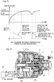
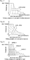
- a loss in the speed reducer is mainly attributable to rolling resistance in a bearing section, and/or sliding resistance in a sliding portion. Given that bearing specifications and gaps inside the speed reducer are fixed, the magnitude of a loss due to such resistance depends on the rotation frequency (see Fig. 7 ).
- core losses, copper losses, and mechanical losses occupy a large part of a total loss.
- the magnitude of the copper losses depends on a coil electric current
- the magnitude of the core losses depends on the coil electric current and the rotation frequency
- the magnitude of the mechanical losses depends on the rotation frequency. Therefore, the copper losses occupy a large part of the total loss in low-speed high-torque operation
- the core losses and the mechanical losses occupy a large part of the total loss in high-speed low-torque operation (see Fig. 8 ).
- a loss map representing a total loss in an in-wheel motor drive device unit in accordance with the motor rotation frequency and motor torque as illustrated in Fig. 9 has an operation range A, which is occupied by losses attributable to the motor, and an operation range C, which is occupied by losses attributable to the motor and the speed reducer.
- An operation range B is where losses in the speed reducer and the motor are so small that abnormality detection does not need to be performed while the motor rotation frequency and the motor torque are fall within this range.
- the total loss in the in-wheel motor drive device unit in the low-speed high-torque operation which is represented by range A, is largely attributable to the copper losses in the motor.
- an increase rate of the coil temperature is greater than an increase rate of the temperature of a lubricating oil, such that a change of temperature of the lubricating oil is greatly behind a change of coil temperature.
- the high-speed low-torque operation which is represented by range C
- the total loss in the in-wheel motor drive device unit is largely occupied by the core losses in the motor and the losses in the speed reducer, and the increase rate of the temperature of the lubricating oil is therefore greater than the increase rate of the coil temperature.
- a coil temperature sensor is typically disposed between slots of a stator, and the lubricating oil therefore does not easily get on the coil temperature sensor, which makes it unlikely to directly measure the temperature of the lubricating oil with the coil temperature sensor.
- the temperatures of coils and the stator are increased by the lubricating oil getting on the coils and a stator core, and the coil temperature sensor responds to an increase in the coil temperature caused by conduction and transmission of the heat.
- An output of the coil temperature sensor therefore involves a significant delay in a response to the temperature of the lubricating oil.
- Patent Document 1 JP Laid-open Patent Publication No. 2012-178917
- the in-wheel motor drive device In order to detect an abnormality in the in-wheel motor drive device, it is conceivable to detect a temperature, particularly the temperature of the coil and the temperature of the lubricating oil.
- the coil temperature sensor is disposed between the slots of the stator to avoid an influence of the lubricating oil, and the lubricating oil does not easily get thereon. Meanwhile, a sensor to measure the temperature of the lubricating oil needs to be disposed at the most downstream position in the speed reducer to detect an abnormality in the speed reducer with high precision, and it is therefore unlikely to estimate the coil temperature of the motor with this sensor.
- the temperature of a motor coil of a motor section of an in-wheel motor drive device is measured, and a derivative of the coil temperature is calculated, and when the derivative has exceeded a certain threshold value, it is determined that an abnormality has occurred, and output control is performed (see Patent Document 1). It is difficult to detect an abnormality in the in-wheel motor drive device with high precision with only the coil temperature, because an output of a sensor that measures the coil temperature involves a delay in response to an increase in the temperature of the lubricating oil in the high-speed low-torque operation. If such a delay in response permits the temperature of the lubricating oil to increase, for example, beyond the heat-resistant temperature of a resin material of the speed reducer, this in turn may cause an abnormality in the speed reducer.
- An object of the present invention is to provide an in-wheel motor drive device which measures both the temperature of a lubricating oil and the temperature of a motor coil, and which is able to detect an abnormality with high precision over the entire operation range of a motor.
- An in-wheel motor drive device includes: an electric motor 1 configured to drive a wheel; a wheel bearing 5 configured to rotatably support the wheel; a speed reducer 2 configured to transmit rotation with a speed that is reduce with respect to that of rotation of the electric motor 1 to the wheel bearing 5; a lubricating oil supply mechanism Jk including a lubricating oil passage 29 formed in a lower portion of the speed reducer 2, and a supply oil passage 30 configured to supply a lubricating oil from the lubricating oil passage 29 to the electric motor 1; an oil temperature sensor Sb disposed in the lubricating oil passage 29 in the speed reducer 2 to measure a temperature of the lubricating oil in the lubricating oil passage 29; a coil temperature sensor Sa disposed on a stator 9 of the electric motor 1 to measure a temperature of a motor coil 78; and a controller U1 configured to control the electric motor 1, and including a motor output limiting module 95 configured to limit an electric current in the electric motor 1 when at
- the "predefined threshold value" is determined in advance based on, for example, an experiment or simulation.
- Limiting the electric current in the electric motor includes reducing the electric current in the electric motor to "zero".
- the motor output limiting module 95 of the controller U1 determines whether at least one of the temperature measured by the oil temperature sensor Sb and the coil temperature measured by the coil temperature sensor Sa has exceeded a corresponding determined first threshold value. If it is determined that at least one of the temperature measured by the oil temperature sensor Sb and the coil temperature measured by the coil temperature sensor Sa has exceeded the threshold value, the motor output limiting module 95 limits the electric current in the electric motor 1.
- the electric current in the electric motor 1 is limited without delay, so that an increase in the coil temperature of the electric motor 1 can be inhibited to prevent an overload on the electric motor 1, and an increase in the temperature of the lubricating oil can be inhibited to prevent an abnormality in the speed reducer 2. Therefore, abnormality detection can be achieved with high precision over the entire operation range of the electric motor 1 from the low-speed high-torque operation to the high-speed low-torque operation.
- the corresponding threshold value for each of the oil temperature sensor Sb and the coil temperature sensor Sa may include a first threshold value and a second threshold value greater than the first threshold value, and the motor output limiting module 95 may start limiting an output to the electric motor 1 when at least one of the temperature measured by the oil temperature sensor Sb and the temperature measured by the coil temperature sensor Sa has exceeded the first threshold value, and reduce the electric current in the electric motor 1 to zero when the at least one of the temperature measured by the oil temperature sensor Sb and the temperature measured by the coil temperature sensor Sa has exceeded the second threshold value.
- Each of the first and second threshold values is determined based on, for example, an experiment or simulation.
- the motor output limiting module 95 may reduce a torque command value to be inputted to the electric motor 1 at a fixed rate when at least one of the temperature measured by the oil temperature sensor Sb and the temperature measured by the coil temperature sensor Sa has exceeded the first threshold value.
- the fixed rate includes predefined fixed rates that are determined for the respective oil and coil temperatures.
- the predefined fixed rate i.e., the fixed value
- the predefined fixed rate is used depending on whether the temperature that has exceeded the first threshold value is the oil temperature or the coil temperature. That is, the predefined fixed rates are different from each other for the respective oil and coil temperatures.
- Each of the predefined fixed rates is determined appropriately based on, for example, an experiment or simulation.
- the motor output limiting module 95 may stop limiting the electric current in the electric motor 1 at that time.
- the certain time period is determined based on a test or simulation.
- the lubricating oil supply mechanism Jk may include a pump 28 configured to supply the lubricating oil from the lubricating oil passage 29 to the electric motor 1 through the supply oil passage 30, the pump 28 being disposed between the electric motor 1 and the speed reducer 2 so as to be concentric with the electric motor 1 and the speed reducer 2.
- the pump 28 may be provided outside of an in-wheel motor drive device unit enclosing the electric motor 1, the wheel bearing 5, and the speed reducer 2.
- a lubricating oil tank in a body of the device can be dispensed with, so that the number of oil passages to be provided in the device unit can be reduced. This allows the device unit to be made compact. Therefore, the in-wheel motor drive device is adapted to be mounted in various kinds of vehicles, so that the versatility of the in-wheel motor drive device can be improved.
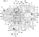
- the in-wheel motor drive device includes: an electric motor 1 configured to drive a wheel; a speed reducer 2 configured to reduce the speed of rotation of the electric motor 1; a wheel bearing 5 caused to rotate by an output member 4 coaxial with an input shaft 3 (hereinafter, referred to as a "speed reducer input shaft 3") of the speed reducer 2; a lubricating oil supply mechanism Jk; and a controller U1 (see Fig. 4 ).
- the speed reducer 2 is interposed between the wheel bearing 5 and the electric motor 1.
- a wheel hub of a drive wheel supported by the wheel bearing 5 is concentrically coupled to a motor rotating shaft 6 of the electric motor 1, the speed reducer input shaft 3, and the output member 4.
- a suspension (not shown) of a vehicle is coupled to a speed reducer housing 7 that houses the speed reducer 2.
- an outer side and an inner side i.e., a side closer to the longitudinal center of the vehicle body, with the in-wheel motor drive device assembled in the vehicle, are referred to as an outboard side and an inboard side, respectively.
- the electric motor 1 includes an IPM motor (a so-called Interior Permanent Magnet synchronous motor) of a radial gap type.
- IPM motor a so-called Interior Permanent Magnet synchronous motor
- a radial gap is defined between a motor stator 9 fixed to a motor housing 8 and a motor rotor 10 attached to the motor rotating shaft 6.
- bearings 11 and 12 are provided to be separated from each other in an axial direction.
- the motor rotating shaft 6 is rotatably supported by the bearings 11 and 12.
- the motor rotating shaft 6 is configured to transmit a driving force of the electric motor 1 to the speed reducer 2.
- a flange portion 6a extending radially outward is provided near an axial middle of the motor rotating shaft 6,
- a rotor fixing member 13 is provided on the flange portion 6a .
- the motor rotor 10 is attached to the rotor fixing member 13.
- a coil temperature sensor Sa is disposed on the motor stator 9 of the electric motor 1 to measure the temperature of a motor coil 78.
- the coil temperature sensor Sa includes, for example, a thermistor. The temperature measured by the coil temperature sensor Sa is used to make a determination in control of limiting an electric current in the electric motor 1 as described below.
- the speed reducer input shaft 3 is spline-fitted to the motor rotating shaft 6, with one axial end of the speed reducer input shaft 3 extending into the motor rotating shaft 6.
- the output member 4 includes a cup portion 4a in which a bearing 14a is fitted.
- the cup portions 4a is coupled to a tubular joining member 26 through inner pins 22.
- a bearing 14b is fitted in the tubular joining member 26 .
- the speed reducer input shaft 3 is rotatably supported by the bearings 14a and 14b.
- eccentric portions 15 and 16 are provided at the outer circumferential surface of the speed reducer input shaft 3 inside the speed reducer housing 7 displaced portions 15 and 16 are provided.
- the eccentric portions 15 and 16 are displaced 180 degrees in phase from each other such that centrifugal forces generated by eccentric motions of the eccentric portions 15 and 16 are cancelled.
- the speed reducer 2 includes a cycloidal speed reducer.
- the cycloidal speed reducer includes an outer pin housing Ih, the speed reducer input shaft 3, curvilinear plates 17 and 18, a plurality of outer pins 19, the inner pins 22, and a counter weight 21.
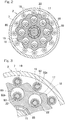
- Fig. 2 is a sectional view of a speed reducer section taken along line II-II in Fig. 1 .
- the two curvilinear plates 17 and 18, each of which has an external shape formed by a smooth wavelike trochoidal curve, are attached to the eccentric portions 15 and 16 through bearings 85, respectively.
- the plurality of outer pins 19, which guide the eccentric motions of the respective curvilinear plates 17 and 18 at the outer peripheries thereof, are fitted to the outer pin housing Ih (see Fig. 1 ) inside the speed reducer housing 7.
- the plurality of inner pins 22, which are fitted to the cup portion 4a (see Fig. 1 ), are inserted in and engaged with a plurality of round through holes 89, which are formed in each of the curvilinear plates 17 and 18.
- needle roller bearings 92 and 93 are fitted to the outer and inner pins 19 and 22, respectively.
- Each outer pin 19 is supported at both ends thereof by the needle roller bearing 92 so as to be in rolling contact with the outer peripheral surface of each of the curvilinear plates 17 and 18.
- an outer ring 93a of the needle roller bearing 93 is in rolling contact with the inner peripheries of the corresponding round through holes 89 of the curvilinear plates 17 and 18. Accordingly, contact resistance between outer pins 19 and the outer peripheries of the curvilinear plates 17 and 18 and contact resistance between inner pins 22 and the inner peripheries of the corresponding through holes 89 are reduced.
- the eccentric motions of the curvilinear plates 17 and 18 can be smoothly transmitted as rotational motion to an inner member 5a of the wheel bearing 5.
- outer pins 19 are engaged with the outer peripheral surfaces of the curvilinear plates 17 and 18 making the eccentric motions so as to be in rolling contact therewith, and inner pins 22 are engaged with the round through holes 89 (see Fig.
- the lubricating oil supply mechanism Jk includes a shaft oil supply mechanism configured to supply a lubricating oil to be used for both lubricating the speed reducer 2 and cooling the electric motor 1, through an interior of the motor rotating shaft 6.
- the lubricating oil supply mechanism Jk includes a lubricating oil passage 29, a supply oil passage 30, a discharge oil passage 38, and a pump 28.
- the lubricating oil passage 29 is formed inside the speed reducer housing 7 of the speed reducer 2.
- the lubricating oil passage 29 includes a lubricating oil tank 29a.
- the lubricating oil tank 29a is positioned at a lower portion of the speed reducer housing 7 to store the lubricating oil, and is in communication with a lower space inside the motor housing 8.
- the supply oil passage 30 configured to supply the lubricating oil from the lubricating oil tank 29a to the electric motor 1 and the speed reducer 2.
- the supply oil passage 30 includes a suction-side oil passage 30a, a discharge-side oil passage 30b, a housing outer periphery-side oil passage 30c, a communicating passage 30d, a motor rotating shaft oil passage 30e, and a speed reducer oil passage 30f.
- the suction-side oil passage 30a extends from a suction port in the lubricating oil tank 29a to an inlet port of the pump 28, and is formed in the lower portion of the speed reducer housing 7 and a lower portion of the motor housing 8.
- the discharge-side oil passage 30b in communication with a discharge port of the pump 28, and extends substantially radially outward inside the motor housing 8.
- the housing outer periphery-side oil passage 30c is in communication with the discharge-side oil passage 30b, and extends along the axial direction from the outboard side to the inboard side inside the motor housing 8.
- the communicating passage 30d is formed at an inboard-side end of the motor housing 8, and an inlet of the communicating passage 30d is connected to the housing outer periphery-side oil passage 30c, and an outlet of the communicating passage 30d is connected to the motor rotating shaft oil passage 30e.
- the motor rotating shaft oil passage 30e extends along a central axis of the motor rotating shaft 6. A portion of the lubricating oil that is guided into the motor rotating shaft oil passage 30e from the communicating passage 30d passes through a through hole extending radially outward through the motor rotating shaft 6 and the flange portion 6a and then through an oil passage extending radially outward and formed inside the rotor fixing member 13, thereby cooling the motor rotor 10. Further, the lubricating oil is ejected to the inner peripheral surface of coil ends through an oil outlet of the oil passage by a centrifugal force of the motor rotor 10 and pressure by the pump 28, thereby cooling the coil 78.
- the speed reducer oil passage 30f is formed in the speed reducer 2 to supply the lubricating oil to the speed reducer 2.
- the speed reducer oil passage 30f includes an input shaft oil passage 36 and oil supply ports 37.
- the input shaft oil passage 36 is in communication with the motor rotating shaft oil passage 30e, and extends in the axial direction inside the speed reducer input shaft 3 from an inboard-side end of the speed reducer input shaft 3 to the outboard side.
- the oil supply ports 37 extend radially outward from axial positions in the input shaft oil passage 36 at which the eccentric portions 15 and 16 are provided.
- the discharge oil passage 38 which discharges the lubricating oil that has lubricated the speed reducer 2, to the lubricating oil tank 29a, is formed in the speed reducer housing 7.
- the pump 28 sucks the lubricating oil stored in the lubricating oil tank 29a, through the suction port in the lubricating oil tank 29a and the suction-side oil passage 30a, and causes the lubricating oil to flow sequentially through the discharge-side oil passage 30b, the housing outer periphery-side oil passage 30c, and the communicating passage 30d to the motor rotating shaft oil passage 30e and the speed reducer oil passage 30f to achieve a circulation.
- the pump 28 is disposed between the electric motor 1 and the speed reducer 2 so as to be concentric with the electric motor 1 and the speed reducer 2.
- the pump 28 may be a cycloidal pump including an inner rotor (not shown) caused to rotate by the rotation of the output member 4, an outer rotor that rotates following the rotation of the inner rotor, a pump chamber, an inlet port, and a discharge port (all of which are not shown).
- the lubricating oil is guided from the communicating passage 30d into the motor rotating shaft oil passage 30e. A portion of the lubricating oil cools the motor rotor 10 and the coils 78 as mentioned above, then moves downward inside the motor housing 8 by gravity, and flows into the lubricating oil tank 29a, which is in communication with the lower space inside the motor housing 8.
- a portion of the lubricating oil that is guided from the motor rotating shaft oil passage 30e to each oil supply port 37 through the input shaft oil passage 36 is discharged through a radially outer opening end of the oil supply port 37.
- a centrifugal force and the pressure by the pump 28 act on this lubricating oil, and the lubricating oil accordingly moves radially outward inside the speed reducer housing 7 while lubricating various components of the speed reducer 2.
- the lubricating oil moves downward by gravity into the lubricating oil tank 29a through the oil discharge port 38, and is stored in the lubricating oil tank 29a.
- An oil temperature sensor Sb which measures the temperature of the lubricating oil, is disposed in the lubricating oil tank 29a.
- the oil temperature sensor Sb is, for example, a thermistor. The temperature measured by the oil temperature sensor Sb is used to make a determination in the control of limiting the electric current in the electric motor 1 as described below.
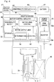
- Fig. 4 is a block diagram of a control system of the in-wheel motor drive device.
- the controller U1 includes an ECU 43, which acts as an electronic control unit configured to perform overall control of the vehicle (the automobile), and an inverter device 44 configured to perform control of the electric motor 1, which acts as a traction motor responding to commands from the ECU 43.
- the inverter device 44 includes a power circuit section 45 provided for each electric motor 1, and a motor control circuitry 46 which controls the power circuit section 45.
- the motor control circuitry 46 is configured to output various types of information, including various measured values and control values related to the in-wheel motor drive device, which are stored in the motor control circuitry 46, to the ECU 43.
- the power circuit section 45 includes an inverter 45a configured to convert a direct-current power from a battery 47 into a three-phase alternating-current power to be used to drive the electric motor 1, and also includes a PWM driver 45b configured to control the inverter 45a.
- the inverter 45a includes a plurality of semiconductor switching devices (not shown), and the PWM driver 45b performs pulse-width modulation on a received electric current command by generating ON/OFF commands to the semiconductor switching devices.
- the motor control circuitry 46 includes a computer, programs which are executed by the computer, and various electronic circuits.
- the motor control circuitry 46 includes a motor drive control module 48 which serves as a basic control component.
- the motor drive control module 48 is configured to convert acceleration or deceleration commands, such as torque commands, supplied from the ECU 43, which serves as an upper-level control unit, into the electric current commands, and supply the electric current commands to the PWM driver 45b.
- the motor drive control module 48 obtains, from an electric current sensor 35, a motor electric current that flows from the inverter 45a to the electric motor 1, and performs an electric current feedback control.
- the motor drive control module 48 obtains a rotational angle of the motor rotor of the electric motor 1 from an angle sensor 49 and performs a vector control.
- the motor control circuitry 46 includes a motor output limiting module 95, an abnormality notification module 41, and a storage module 50.
- the motor output limiting module 95 is configured to limit the electric current in the electric motor 1 when at least one of the temperature (referred to as an "oil temperature") measured by the oil temperature sensor Sb and the temperature (referred to as a "coil temperature") of the motor coil measured by the coil temperature sensor Sa has exceeded a corresponding predefined threshold value.
- the motor output limiting module 95 includes a determination submodule 39 and a control submodule 40.
- the determination submodule 39 is configured to determine continuously (i.e., at short time intervals) whether the oil temperature and the coil temperature have exceeded the respective predefined threshold values.
- the threshold value for the oil temperature is determined in advance through an experiment or simulation. For example, the value is set based on the relationship between the oil temperature and the viscosity of the lubricating oil, and/or the relationship between the viscosity of the lubricating oil and rotational resistance of the electric motor 1.
- the threshold value for the coil temperature is determined in advance appropriately through an experiment or simulation. For example, the value is set based on the relationship between time and the coil temperature that causes insulation in the motor coil.
- each threshold value is stored in the storage module 50 so as to be rewritable.
- each of the threshold value for the temperature measured by the oil temperature sensor Sb and the threshold value for the temperature measured by the coil temperature sensor Sa includes a first threshold value and a second threshold value greater than the first threshold value.
- control submodule 40 instructs the power circuit section 45 via the motor drive control module 48 to reduce the electric current in the electric motor 1.
- Fig. 5 is a diagram illustrating the relationship between the threshold values for the coil temperature and motor input. Although not shown, the threshold values for the oil temperature and the motor input have a relationship similar to the relationship as illustrated in Fig. 5 . A description will be given with reference to Fig. 4 as well. For example, assume that, of the measured coil temperature and the measured oil temperature, the measured coil temperature has exceeded the corresponding first threshold value. When the measured coil temperature has exceeded the first threshold value, the control submodule 40 starts limiting the output to the electric motor 1.
- the control submodule 40 instructs the power circuit section 45 via the motor drive control module 48 to reduce a torque command value to be inputted to the electric motor 1 at a fixed rate (i.e., with a fixed gradient).
- the fixed rate includes fixed rates which are determined in advance for the respective oil temperature and coil temperature.
- the control submodule 40 instructs the power circuit section 45 via the motor drive control module 48 to reduce the electric current in the electric motor 1 to zero.
- the control submodule 40 stops limiting the output to the electric motor 1 at that time.
- the abnormality notification module 41 outputs abnormality occurrence information to the ECU 43 when the determination submodule 39 has determined that at least one of the measured oil temperature and the measured coil temperature has exceeded the corresponding first threshold value.
- an abnormality display module 42 in the ECU 43 causes a display device 27, such as a console panel of the vehicle, for example, to perform a display for reporting an abnormality.
- the determination submodule 39 in the motor output limiting module 95 determines whether at least one of the measured oil temperature and the measured coil temperature has exceeded the corresponding predefined threshold value. If it is determined that at least one of the measured oil temperature and the measured coil temperature has exceeded the threshold value, the control submodule 40 instructs the power circuit section 45 via the motor drive control module 48 to reduce the torque command value to be inputted to the electric motor 1.
- the coil temperature measured by the coil temperature sensor Sa is used to determine to limit the electric current in the electric motor 1, and this can prevent a delay in detecting an increase in the coil temperature, enabling precise abnormality detection.
- the coil temperature sensor Sa In high-speed low-torque operation, core losses in the motor and losses in the speed reducer occupy a large part of the total loss in the in-wheel motor drive device. Therefore, simply measuring the coil temperature with the coil temperature sensor Sa would allow an output of the sensor to respond to an increase in the temperature of the lubricating oil, which cools the speed reducer, after a delay, which may lead to an increase in the temperature of the speed reducer.
- the oil temperature is measured with the oil temperature sensor Sb to determine to limit the electric current in the electric motor 1, and this can prevent a delay in detecting an increase in the temperature of the lubricating oil, thereby preventing an abnormality in the speed reducer 2.
- the electric current in the electric motor 1 is limited without delay, so that an increase in the coil temperature of the electric motor 1 can be inhibited to prevent an overload on the electric motor 1, and an increase in the temperature of the lubricating oil can be inhibited to prevent an abnormality in the speed reducer 2. Therefore, abnormality detection can be achieved with high precision over the entire operation range of the electric motor 1 from the low-speed high-torque operation to the high-speed low-torque operation.
- the motor output limiting module 95 starts limiting the output to the electric motor 1 when at least one of the measured oil temperature and the measured coil temperature has exceeded the corresponding first threshold value, and reduces the electric current to the electric motor 1 to zero when the at least one of the measured oil temperature and the measured coil temperature has exceeded the corresponding second threshold value.
- the motor output limiting module 95 reduces the torque command value to be inputted to the electric motor 1 at the fixed rate when at least one of the temperature measured by the oil temperature sensor Sb and the temperature measured by the coil temperature sensor Sa has exceeded the first threshold value, and this can prevent a sharp change in the torque command value in accordance with an operation of the accelerator.
- a pump 28 may be provided outside of an in-wheel motor drive device unit enclosing an electric motor 1, a wheel bearing 5, and a speed reducer 2.
- the pump 28 may be driven by a driving source different from that for this in-wheel motor drive device.
- a lubricating oil tank in a speed reducer housing 7 can be dispensed with, so that the number of oil passages to be provided in a motor housing 8 can be reduced.
- the in-wheel motor drive device is adapted to be mounted in various kinds of vehicles, so that the versatility of the in-wheel motor drive device can be improved.
- the motor output limiting module may be configured to reduce a motor electric current to a rate (for example, 90%) determined for a present motor electric current or to a determined value when at least one of the measured temperatures has exceeded the corresponding first threshold value.
- the motor output limiting module may be configured to reduce the motor electric current with a fixed gradient (i.e., at a fixed rate) when at least one of the measured temperatures has exceeded the corresponding first threshold value, and reduce the motor electric current with a gradient steeper than the fixed gradient, that is, at a rate greater than the aforementioned rate, when the at least one of the measured temperatures has exceeded the second threshold value.
- the gradient of the motor electric current may not necessarily be linear, but may be, for example, a gradient of a quadratic curve or the like.
- the oil temperature sensor may be disposed in the lubricating oil passage in the speed reducer and outside of the lubricating oil tank.
- the speed reducer is not limited thereto, and may include a planetary speed reducer, a speed reducer with two parallel shafts, and other speed reducers.
Landscapes
- Engineering & Computer Science (AREA)
- Power Engineering (AREA)
- Transportation (AREA)
- Mechanical Engineering (AREA)
- Sustainable Development (AREA)
- Sustainable Energy (AREA)
- Life Sciences & Earth Sciences (AREA)
- Chemical & Material Sciences (AREA)
- Combustion & Propulsion (AREA)
- Microelectronics & Electronic Packaging (AREA)
- Arrangement Or Mounting Of Propulsion Units For Vehicles (AREA)
- Electric Propulsion And Braking For Vehicles (AREA)
- Control Of Ac Motors In General (AREA)
Abstract
Description
- This application is based on and claims Convention priority to
Japanese patent application No. 2014-013290, filed January 28, 2014 - The present invention relates to an in-wheel motor drive device, and also relates to a technique for detecting an abnormality in the in-wheel motor drive device with high precision using a coil temperature sensor and an oil temperature sensor.
- An in-wheel motor drive device includes a speed reducer, a motor, and a wheel bearing. A loss in the in-wheel motor drive device amounts to the sum of losses in those components of the in-wheel motor drive device. A loss in the speed reducer is mainly attributable to rolling resistance in a bearing section, and/or sliding resistance in a sliding portion. Given that bearing specifications and gaps inside the speed reducer are fixed, the magnitude of a loss due to such resistance depends on the rotation frequency (see
Fig. 7 ). - In the motor, core losses, copper losses, and mechanical losses occupy a large part of a total loss. The magnitude of the copper losses depends on a coil electric current, the magnitude of the core losses depends on the coil electric current and the rotation frequency, and the magnitude of the mechanical losses depends on the rotation frequency. Therefore, the copper losses occupy a large part of the total loss in low-speed high-torque operation, while the core losses and the mechanical losses occupy a large part of the total loss in high-speed low-torque operation (see
Fig. 8 ). - Accordingly, a loss map representing a total loss in an in-wheel motor drive device unit in accordance with the motor rotation frequency and motor torque as illustrated in
Fig. 9 has an operation range A, which is occupied by losses attributable to the motor, and an operation range C, which is occupied by losses attributable to the motor and the speed reducer. An operation range B is where losses in the speed reducer and the motor are so small that abnormality detection does not need to be performed while the motor rotation frequency and the motor torque are fall within this range. - The total loss in the in-wheel motor drive device unit in the low-speed high-torque operation, which is represented by range A, is largely attributable to the copper losses in the motor. As a result, in the low-speed high-torque operation, an increase rate of the coil temperature is greater than an increase rate of the temperature of a lubricating oil, such that a change of temperature of the lubricating oil is greatly behind a change of coil temperature. Meanwhile, in the high-speed low-torque operation, which is represented by range C, the total loss in the in-wheel motor drive device unit is largely occupied by the core losses in the motor and the losses in the speed reducer, and the increase rate of the temperature of the lubricating oil is therefore greater than the increase rate of the coil temperature.
- A coil temperature sensor is typically disposed between slots of a stator, and the lubricating oil therefore does not easily get on the coil temperature sensor, which makes it unlikely to directly measure the temperature of the lubricating oil with the coil temperature sensor. The temperatures of coils and the stator are increased by the lubricating oil getting on the coils and a stator core, and the coil temperature sensor responds to an increase in the coil temperature caused by conduction and transmission of the heat. An output of the coil temperature sensor therefore involves a significant delay in a response to the temperature of the lubricating oil.
- [Patent Document 1]
JP Laid-open Patent Publication No. 2012-178917 - In order to detect an abnormality in the in-wheel motor drive device, it is conceivable to detect a temperature, particularly the temperature of the coil and the temperature of the lubricating oil. The coil temperature sensor is disposed between the slots of the stator to avoid an influence of the lubricating oil, and the lubricating oil does not easily get thereon. Meanwhile, a sensor to measure the temperature of the lubricating oil needs to be disposed at the most downstream position in the speed reducer to detect an abnormality in the speed reducer with high precision, and it is therefore unlikely to estimate the coil temperature of the motor with this sensor.
- It has been proposed in related art to dispose a temperature sensor for the lubricating oil at the most downstream position in a lubrication passage in the speed reducer in the in-wheel motor drive device. In the case where abnormality detection is performed with only the oil temperature sensor over the entire operation range of an in-wheel motor, it is difficult to detect an abnormality in the in-wheel motor drive device with precision, because the temperature of the lubricating oil responds to an increase in the coil temperature after a significant delay in the low-speed high-torque operation. If such a delay in response permits the coil temperature to continue to increase so as to exceed the heat-resistant temperature of the coil, this in turn may cause an overload on the motor.
- In another related-art technique, the temperature of a motor coil of a motor section of an in-wheel motor drive device is measured, and a derivative of the coil temperature is calculated, and when the derivative has exceeded a certain threshold value, it is determined that an abnormality has occurred, and output control is performed (see Patent Document 1). It is difficult to detect an abnormality in the in-wheel motor drive device with high precision with only the coil temperature, because an output of a sensor that measures the coil temperature involves a delay in response to an increase in the temperature of the lubricating oil in the high-speed low-torque operation. If such a delay in response permits the temperature of the lubricating oil to increase, for example, beyond the heat-resistant temperature of a resin material of the speed reducer, this in turn may cause an abnormality in the speed reducer.
- An object of the present invention is to provide an in-wheel motor drive device which measures both the temperature of a lubricating oil and the temperature of a motor coil, and which is able to detect an abnormality with high precision over the entire operation range of a motor.
- The following description is made with reference to reference numerals in embodiments for the sake of convenience and easier understanding.
- An in-wheel motor drive device according to one aspect of the present invention includes: an
electric motor 1 configured to drive a wheel; a wheel bearing 5 configured to rotatably support the wheel; aspeed reducer 2 configured to transmit rotation with a speed that is reduce with respect to that of rotation of theelectric motor 1 to the wheel bearing 5; a lubricating oil supply mechanism Jk including a lubricating oil passage 29 formed in a lower portion of thespeed reducer 2, and asupply oil passage 30 configured to supply a lubricating oil from the lubricating oil passage 29 to theelectric motor 1; an oil temperature sensor Sb disposed in the lubricating oil passage 29 in thespeed reducer 2 to measure a temperature of the lubricating oil in the lubricating oil passage 29; a coil temperature sensor Sa disposed on astator 9 of theelectric motor 1 to measure a temperature of amotor coil 78; and a controller U1 configured to control theelectric motor 1, and including a motoroutput limiting module 95 configured to limit an electric current in theelectric motor 1 when at least one of the temperature measured by the oil temperature sensor Sb and the temperature measured by the coil temperature sensor Sa has exceeded a corresponding predefined threshold value. - The "predefined threshold value" is determined in advance based on, for example, an experiment or simulation.
- Limiting the electric current in the electric motor includes reducing the electric current in the electric motor to "zero".
- According to this configuration, the oil temperature sensor Sb disposed in the lubricating oil passage 29 in the speed reducer 2 continuously (i.e., at short time intervals) or regularly measures the temperature of the lubricating oil. The coil temperature sensor Sa disposed on the
stator 9 continuously (i.e., at short time intervals) or regularly measures the temperature of themotor coil 78. The motoroutput limiting module 95 of the controller U1 determines whether at least one of the temperature measured by the oil temperature sensor Sb and the coil temperature measured by the coil temperature sensor Sa has exceeded a corresponding determined first threshold value. If it is determined that at least one of the temperature measured by the oil temperature sensor Sb and the coil temperature measured by the coil temperature sensor Sa has exceeded the threshold value, the motoroutput limiting module 95 limits the electric current in theelectric motor 1. - Heat generation due to losses in the in-wheel motor drive device in low-speed high-torque operation is largely attributable to copper losses in the motor. Therefore, it would be difficult to detect an increase in the coil temperature without a delay by simply measuring the temperature of the lubricating oil with the oil temperature sensor Sb, because the oil temperature responds to the increase in the coil temperature after a delay. In contrast, in this configuration, the coil temperature measured by the coil temperature sensor Sa is used to limit the electric current in the
electric motor 1, and this can prevent a delay in detecting an increase in the coil temperature, enabling precise abnormality detection. - In high-speed low-torque operation, core losses in the motor and losses in the speed reducer occupy a large part of the total loss in the in-wheel motor drive device. Therefore, simply measuring the coil temperature with the coil temperature sensor Sa would allow an output of the sensor to respond to an increase in the temperature of the lubricating oil, which cools the speed reducer, after a delay, which may lead to an increase in the temperature of the speed reducer. In contrast, in this configuration, the oil temperature is measured with the oil temperature sensor Sb to determine to limit the electric current in the
electric motor 1, and this can prevent a delay in detecting an increase in the temperature of the lubricating oil, thereby preventing an abnormality in thespeed reducer 2. - As described above, the electric current in the
electric motor 1 is limited without delay, so that an increase in the coil temperature of theelectric motor 1 can be inhibited to prevent an overload on theelectric motor 1, and an increase in the temperature of the lubricating oil can be inhibited to prevent an abnormality in thespeed reducer 2. Therefore, abnormality detection can be achieved with high precision over the entire operation range of theelectric motor 1 from the low-speed high-torque operation to the high-speed low-torque operation. - The corresponding threshold value for each of the oil temperature sensor Sb and the coil temperature sensor Sa may include a first threshold value and a second threshold value greater than the first threshold value, and the motor
output limiting module 95 may start limiting an output to theelectric motor 1 when at least one of the temperature measured by the oil temperature sensor Sb and the temperature measured by the coil temperature sensor Sa has exceeded the first threshold value, and reduce the electric current in theelectric motor 1 to zero when the at least one of the temperature measured by the oil temperature sensor Sb and the temperature measured by the coil temperature sensor Sa has exceeded the second threshold value. - Each of the first and second threshold values is determined based on, for example, an experiment or simulation.
- By limiting the output to the
electric motor 1 in a stepwise manner as described above, a driver who operates an accelerator can be prevented from having an uncomfortable feeling, so that smooth running of a vehicle can be achieved. - The motor
output limiting module 95 may reduce a torque command value to be inputted to theelectric motor 1 at a fixed rate when at least one of the temperature measured by the oil temperature sensor Sb and the temperature measured by the coil temperature sensor Sa has exceeded the first threshold value. The fixed rate includes predefined fixed rates that are determined for the respective oil and coil temperatures. - As the fixed rate, the predefined fixed rate (i.e., the fixed value) that is determined for the oil or coil temperature is used depending on whether the temperature that has exceeded the first threshold value is the oil temperature or the coil temperature. That is, the predefined fixed rates are different from each other for the respective oil and coil temperatures.
- Each of the predefined fixed rates is determined appropriately based on, for example, an experiment or simulation.
- By reducing the torque command value with a fixed gradient as described above, a sharp change in the torque command value in accordance with an operation of the accelerator can be prevented.
- If, after exceeding the first and second threshold values, at least one of the temperature measured by the oil temperature sensor Sb and the temperature measured by the coil temperature sensor Sa falls below the first threshold value after elapse of a certain time period from a time at which the at least one of the temperature measured by the oil temperature sensor Sb and the temperature measured by the coil temperature sensor Sa exceeds the second threshold value, the motor
output limiting module 95 may stop limiting the electric current in theelectric motor 1 at that time. The certain time period is determined based on a test or simulation. By stopping the limiting of the electric current in theelectric motor 1, that is, inputting an accelerator command value without changing, on the above condition, a motor torque can be recovered to realize a driving in accordance with an intention of the driver. - The lubricating oil supply mechanism Jk may include a
pump 28 configured to supply the lubricating oil from the lubricating oil passage 29 to theelectric motor 1 through thesupply oil passage 30, thepump 28 being disposed between theelectric motor 1 and thespeed reducer 2 so as to be concentric with theelectric motor 1 and thespeed reducer 2. - The
pump 28 may be provided outside of an in-wheel motor drive device unit enclosing theelectric motor 1, the wheel bearing 5, and the speed reducer 2. In this case, for example, a lubricating oil tank in a body of the device can be dispensed with, so that the number of oil passages to be provided in the device unit can be reduced. This allows the device unit to be made compact. Therefore, the in-wheel motor drive device is adapted to be mounted in various kinds of vehicles, so that the versatility of the in-wheel motor drive device can be improved. - Any combination of at least two constructions, disclosed in the appended claims and/or the specification and/or the accompanying drawings should be construed as included within the scope of the present invention. In particular, any combination of two or more of the appended claims should be equally construed as included within the scope of the present invention.
- In any event, the present invention will become more clearly understood from the following description of preferred embodiments thereof, when taken in conjunction with the accompanying drawings. However, the embodiments and the drawings are given only for the purpose of illustration and explanation, and are not to be taken as limiting the scope of the present invention in any way whatsoever, which scope is to be determined by the appended claims.
- In the accompanying drawings, like reference numerals are used to denote like parts throughout the several views, and:
-
Fig. 1 is a sectional view of an in-wheel motor drive device according to a first embodiment of the present invention; -
Fig. 2 is a sectional view of a speed reducer section taken along line II-II inFig. 1 ; -
Fig. 3 is an enlarged view of a portion ofFig. 2 ; -
Fig. 4 is a block diagram of a control system of the in-wheel motor drive device illustrated inFig. 1 ; -
Fig. 5 is a diagram illustrating the relationship between threshold values with respect to a temperature and motor input; -
Fig. 6 is a sectional view of an in-wheel motor drive device according to a second embodiment of the present invention; -
Fig. 7 is a diagram illustrating a typical example of a loss map of a speed reducer; -
Fig. 8 is a diagram illustrating a typical example of a loss map of a motor; and -
Fig. 9 is a diagram illustrating a typical example of a loss map of an in-wheel motor drive device. - An in-wheel motor drive device according to a first embodiment of the present invention will be described with reference to
Figs. 1 to 5 . As illustrated inFig. 1 , the in-wheel motor drive device includes: anelectric motor 1 configured to drive a wheel; aspeed reducer 2 configured to reduce the speed of rotation of theelectric motor 1; awheel bearing 5 caused to rotate by anoutput member 4 coaxial with an input shaft 3 (hereinafter, referred to as a "speedreducer input shaft 3") of thespeed reducer 2; a lubricating oil supply mechanism Jk; and a controller U1 (seeFig. 4 ). Thespeed reducer 2 is interposed between thewheel bearing 5 and theelectric motor 1. A wheel hub of a drive wheel supported by thewheel bearing 5 is concentrically coupled to amotor rotating shaft 6 of theelectric motor 1, the speedreducer input shaft 3, and theoutput member 4. - A suspension (not shown) of a vehicle is coupled to a
speed reducer housing 7 that houses thespeed reducer 2. Herein, an outer side and an inner side, i.e., a side closer to the longitudinal center of the vehicle body, with the in-wheel motor drive device assembled in the vehicle, are referred to as an outboard side and an inboard side, respectively. - The
electric motor 1 includes an IPM motor (a so-called Interior Permanent Magnet synchronous motor) of a radial gap type. In this type, a radial gap is defined between amotor stator 9 fixed to amotor housing 8 and amotor rotor 10 attached to themotor rotating shaft 6. On themotor housing 8bearings motor rotating shaft 6 is rotatably supported by thebearings - The
motor rotating shaft 6 is configured to transmit a driving force of theelectric motor 1 to thespeed reducer 2. Aflange portion 6a extending radially outward is provided near an axial middle of themotor rotating shaft 6, On theflange portion 6a arotor fixing member 13 is provided. Themotor rotor 10 is attached to therotor fixing member 13. - A coil temperature sensor Sa is disposed on the
motor stator 9 of theelectric motor 1 to measure the temperature of amotor coil 78. The coil temperature sensor Sa includes, for example, a thermistor. The temperature measured by the coil temperature sensor Sa is used to make a determination in control of limiting an electric current in theelectric motor 1 as described below. - The speed
reducer input shaft 3 is spline-fitted to themotor rotating shaft 6, with one axial end of the speedreducer input shaft 3 extending into themotor rotating shaft 6. Theoutput member 4 includes a cup portion 4a in which abearing 14a is fitted. The cup portions 4a is coupled to atubular joining member 26 throughinner pins 22. In the tubular joining member 26 abearing 14b is fitted. The speedreducer input shaft 3 is rotatably supported by thebearings reducer input shaft 3 inside thespeed reducer housing 7eccentric portions eccentric portions eccentric portions - The
speed reducer 2 includes a cycloidal speed reducer. The cycloidal speed reducer includes an outer pin housing Ih, the speedreducer input shaft 3,curvilinear plates outer pins 19, theinner pins 22, and acounter weight 21. -
Fig. 2 is a sectional view of a speed reducer section taken along line II-II inFig. 1 . In thespeed reducer 2, the twocurvilinear plates eccentric portions bearings 85, respectively. The plurality ofouter pins 19, which guide the eccentric motions of the respectivecurvilinear plates Fig. 1 ) inside thespeed reducer housing 7. The plurality ofinner pins 22, which are fitted to the cup portion 4a (seeFig. 1 ), are inserted in and engaged with a plurality of round throughholes 89, which are formed in each of thecurvilinear plates - As shown in an enlarged view of
Fig. 3 ,needle roller bearings inner pins outer pin 19 is supported at both ends thereof by theneedle roller bearing 92 so as to be in rolling contact with the outer peripheral surface of each of thecurvilinear plates inner pin 22, anouter ring 93a of theneedle roller bearing 93 is in rolling contact with the inner peripheries of the corresponding round throughholes 89 of thecurvilinear plates outer pins 19 and the outer peripheries of thecurvilinear plates inner pins 22 and the inner peripheries of the corresponding throughholes 89 are reduced. - Thus, referring to
Fig. 1 , the eccentric motions of thecurvilinear plates inner member 5a of thewheel bearing 5. Specifically, when themotor rotating shaft 6 rotates, each of thecurvilinear plates reducer input shaft 3, which rotates together with themotor rotating shaft 6, makes eccentric motion. At this time,outer pins 19 are engaged with the outer peripheral surfaces of thecurvilinear plates inner pins 22 are engaged with the round through holes 89 (seeFig. 3 ) of thecurvilinear plates curvilinear plates output member 4 and theinner member 5a. Thus, the speed of the rotation of theinner member 5a is reduced from the speed of the rotation of themotor rotating shaft 6. - The lubricating oil supply mechanism Jk includes a shaft oil supply mechanism configured to supply a lubricating oil to be used for both lubricating the
speed reducer 2 and cooling theelectric motor 1, through an interior of themotor rotating shaft 6. The lubricating oil supply mechanism Jk includes a lubricating oil passage 29, asupply oil passage 30, a discharge oil passage 38, and apump 28. The lubricating oil passage 29 is formed inside thespeed reducer housing 7 of thespeed reducer 2. The lubricating oil passage 29 includes a lubricating oil tank 29a. The lubricating oil tank 29a is positioned at a lower portion of thespeed reducer housing 7 to store the lubricating oil, and is in communication with a lower space inside themotor housing 8. - The
supply oil passage 30 configured to supply the lubricating oil from the lubricating oil tank 29a to theelectric motor 1 and thespeed reducer 2. Thesupply oil passage 30 includes a suction-side oil passage 30a, a discharge-side oil passage 30b, a housing outer periphery-side oil passage 30c, a communicatingpassage 30d, a motor rotatingshaft oil passage 30e, and a speedreducer oil passage 30f. The suction-side oil passage 30a extends from a suction port in the lubricating oil tank 29a to an inlet port of thepump 28, and is formed in the lower portion of thespeed reducer housing 7 and a lower portion of themotor housing 8. The discharge-side oil passage 30b in communication with a discharge port of thepump 28, and extends substantially radially outward inside themotor housing 8. - The housing outer periphery-side oil passage 30c is in communication with the discharge-
side oil passage 30b, and extends along the axial direction from the outboard side to the inboard side inside themotor housing 8. The communicatingpassage 30d is formed at an inboard-side end of themotor housing 8, and an inlet of the communicatingpassage 30d is connected to the housing outer periphery-side oil passage 30c, and an outlet of the communicatingpassage 30d is connected to the motor rotatingshaft oil passage 30e. - The motor rotating
shaft oil passage 30e extends along a central axis of themotor rotating shaft 6. A portion of the lubricating oil that is guided into the motor rotatingshaft oil passage 30e from the communicatingpassage 30d passes through a through hole extending radially outward through themotor rotating shaft 6 and theflange portion 6a and then through an oil passage extending radially outward and formed inside therotor fixing member 13, thereby cooling themotor rotor 10. Further, the lubricating oil is ejected to the inner peripheral surface of coil ends through an oil outlet of the oil passage by a centrifugal force of themotor rotor 10 and pressure by thepump 28, thereby cooling thecoil 78. - The speed
reducer oil passage 30f is formed in thespeed reducer 2 to supply the lubricating oil to thespeed reducer 2. The speedreducer oil passage 30f includes an inputshaft oil passage 36 andoil supply ports 37. The inputshaft oil passage 36 is in communication with the motor rotatingshaft oil passage 30e, and extends in the axial direction inside the speedreducer input shaft 3 from an inboard-side end of the speedreducer input shaft 3 to the outboard side. Theoil supply ports 37 extend radially outward from axial positions in the inputshaft oil passage 36 at which theeccentric portions - The discharge oil passage 38, which discharges the lubricating oil that has lubricated the
speed reducer 2, to the lubricating oil tank 29a, is formed in thespeed reducer housing 7. - The
pump 28 sucks the lubricating oil stored in the lubricating oil tank 29a, through the suction port in the lubricating oil tank 29a and the suction-side oil passage 30a, and causes the lubricating oil to flow sequentially through the discharge-side oil passage 30b, the housing outer periphery-side oil passage 30c, and the communicatingpassage 30d to the motor rotatingshaft oil passage 30e and the speedreducer oil passage 30f to achieve a circulation. Thepump 28 is disposed between theelectric motor 1 and thespeed reducer 2 so as to be concentric with theelectric motor 1 and thespeed reducer 2. Thepump 28 may be a cycloidal pump including an inner rotor (not shown) caused to rotate by the rotation of theoutput member 4, an outer rotor that rotates following the rotation of the inner rotor, a pump chamber, an inlet port, and a discharge port (all of which are not shown). - When the rotation of the
output member 4 driven by theelectric motor 1 causes the inner rotor to rotate, the outer rotor rotates following the rotation of the inner rotor. In this period, the inner rotor and the outer rotor rotate about different rotation axes, so that the volume of the pump chamber continuously varies. This causes the lubricating oil stored in the lubricating oil tank 29a to be sucked through the suction port and the suction-side oil passage 30a to flow into thepump 28 through the inlet port, and to be supplied under pressure through the discharge port to the discharge-side oil passage 30b, the housing outer periphery-side oil passage 30c, and the communicatingpassage 30d sequentially. - The lubricating oil is guided from the communicating
passage 30d into the motor rotatingshaft oil passage 30e. A portion of the lubricating oil cools themotor rotor 10 and thecoils 78 as mentioned above, then moves downward inside themotor housing 8 by gravity, and flows into the lubricating oil tank 29a, which is in communication with the lower space inside themotor housing 8. - A portion of the lubricating oil that is guided from the motor rotating
shaft oil passage 30e to eachoil supply port 37 through the inputshaft oil passage 36 is discharged through a radially outer opening end of theoil supply port 37. A centrifugal force and the pressure by thepump 28 act on this lubricating oil, and the lubricating oil accordingly moves radially outward inside thespeed reducer housing 7 while lubricating various components of thespeed reducer 2. Then, the lubricating oil moves downward by gravity into the lubricating oil tank 29a through the oil discharge port 38, and is stored in the lubricating oil tank 29a. An oil temperature sensor Sb, which measures the temperature of the lubricating oil, is disposed in the lubricating oil tank 29a. The oil temperature sensor Sb is, for example, a thermistor. The temperature measured by the oil temperature sensor Sb is used to make a determination in the control of limiting the electric current in theelectric motor 1 as described below. - A control system will now be described below.
-
Fig. 4 is a block diagram of a control system of the in-wheel motor drive device. - The controller U1 includes an
ECU 43, which acts as an electronic control unit configured to perform overall control of the vehicle (the automobile), and aninverter device 44 configured to perform control of theelectric motor 1, which acts as a traction motor responding to commands from theECU 43. Theinverter device 44 includes apower circuit section 45 provided for eachelectric motor 1, and amotor control circuitry 46 which controls thepower circuit section 45. Themotor control circuitry 46 is configured to output various types of information, including various measured values and control values related to the in-wheel motor drive device, which are stored in themotor control circuitry 46, to theECU 43. - The
power circuit section 45 includes aninverter 45a configured to convert a direct-current power from abattery 47 into a three-phase alternating-current power to be used to drive theelectric motor 1, and also includes aPWM driver 45b configured to control theinverter 45a. Theinverter 45a includes a plurality of semiconductor switching devices (not shown), and thePWM driver 45b performs pulse-width modulation on a received electric current command by generating ON/OFF commands to the semiconductor switching devices. - The
motor control circuitry 46 includes a computer, programs which are executed by the computer, and various electronic circuits. Themotor control circuitry 46 includes a motordrive control module 48 which serves as a basic control component. The motordrive control module 48 is configured to convert acceleration or deceleration commands, such as torque commands, supplied from theECU 43, which serves as an upper-level control unit, into the electric current commands, and supply the electric current commands to thePWM driver 45b. The motordrive control module 48 obtains, from an electriccurrent sensor 35, a motor electric current that flows from theinverter 45a to theelectric motor 1, and performs an electric current feedback control. In addition, the motordrive control module 48 obtains a rotational angle of the motor rotor of theelectric motor 1 from anangle sensor 49 and performs a vector control. - The
motor control circuitry 46 includes a motoroutput limiting module 95, anabnormality notification module 41, and astorage module 50. The motoroutput limiting module 95 is configured to limit the electric current in theelectric motor 1 when at least one of the temperature (referred to as an "oil temperature") measured by the oil temperature sensor Sb and the temperature (referred to as a "coil temperature") of the motor coil measured by the coil temperature sensor Sa has exceeded a corresponding predefined threshold value. The motoroutput limiting module 95 includes adetermination submodule 39 and acontrol submodule 40. - The determination submodule 39 is configured to determine continuously (i.e., at short time intervals) whether the oil temperature and the coil temperature have exceeded the respective predefined threshold values. The threshold value for the oil temperature is determined in advance through an experiment or simulation. For example, the value is set based on the relationship between the oil temperature and the viscosity of the lubricating oil, and/or the relationship between the viscosity of the lubricating oil and rotational resistance of the
electric motor 1. The threshold value for the coil temperature is determined in advance appropriately through an experiment or simulation. For example, the value is set based on the relationship between time and the coil temperature that causes insulation in the motor coil. - Each threshold value is stored in the
storage module 50 so as to be rewritable. In this embodiment, each of the threshold value for the temperature measured by the oil temperature sensor Sb and the threshold value for the temperature measured by the coil temperature sensor Sa includes a first threshold value and a second threshold value greater than the first threshold value. - If it is determined that at least one of the measured oil temperature and the measured coil temperature has exceeded the corresponding predefined threshold value, the
control submodule 40 instructs thepower circuit section 45 via the motordrive control module 48 to reduce the electric current in theelectric motor 1. -
Fig. 5 is a diagram illustrating the relationship between the threshold values for the coil temperature and motor input. Although not shown, the threshold values for the oil temperature and the motor input have a relationship similar to the relationship as illustrated inFig. 5 . A description will be given with reference toFig. 4 as well. For example, assume that, of the measured coil temperature and the measured oil temperature, the measured coil temperature has exceeded the corresponding first threshold value. When the measured coil temperature has exceeded the first threshold value, thecontrol submodule 40 starts limiting the output to theelectric motor 1. Specifically, when the measured coil temperature has exceeded the first threshold value, thecontrol submodule 40 instructs thepower circuit section 45 via the motordrive control module 48 to reduce a torque command value to be inputted to theelectric motor 1 at a fixed rate (i.e., with a fixed gradient). The fixed rate includes fixed rates which are determined in advance for the respective oil temperature and coil temperature. - Assume that, of the measured coil temperature and the measured oil temperature, the measured coil temperature, for example, has thereafter exceeded the corresponding second threshold value. When the measured coil temperature has exceeded the second threshold value, the
control submodule 40 instructs thepower circuit section 45 via the motordrive control module 48 to reduce the electric current in theelectric motor 1 to zero. When, after exceeding the first and second threshold values, the measured coil temperature falls below the first threshold value after elapse of a certain time period from the time at which the measured coil temperature exceeds the second threshold value, thecontrol submodule 40 stops limiting the output to theelectric motor 1 at that time. - As illustrated in
Fig. 4 , theabnormality notification module 41 outputs abnormality occurrence information to theECU 43 when thedetermination submodule 39 has determined that at least one of the measured oil temperature and the measured coil temperature has exceeded the corresponding first threshold value. Upon reception of the abnormality occurrence information outputted from theabnormality notification module 41, anabnormality display module 42 in theECU 43 causes adisplay device 27, such as a console panel of the vehicle, for example, to perform a display for reporting an abnormality. - Advantageous effects will now be described below.
- The determination submodule 39 in the motor
output limiting module 95 determines whether at least one of the measured oil temperature and the measured coil temperature has exceeded the corresponding predefined threshold value. If it is determined that at least one of the measured oil temperature and the measured coil temperature has exceeded the threshold value, thecontrol submodule 40 instructs thepower circuit section 45 via the motordrive control module 48 to reduce the torque command value to be inputted to theelectric motor 1. - Heat generation due to losses in the in-wheel motor drive device in low-speed high-torque operation is largely attributable to copper losses in the motor. Therefore, it would be difficult to detect an increase in the coil temperature without a delay by simply measuring the temperature of the lubricating oil with the oil temperature sensor Sb, because the oil temperature responds to the increase in the coil temperature after a delay. In contrast, in the present embodiment, the coil temperature measured by the coil temperature sensor Sa is used to determine to limit the electric current in the
electric motor 1, and this can prevent a delay in detecting an increase in the coil temperature, enabling precise abnormality detection. - In high-speed low-torque operation, core losses in the motor and losses in the speed reducer occupy a large part of the total loss in the in-wheel motor drive device. Therefore, simply measuring the coil temperature with the coil temperature sensor Sa would allow an output of the sensor to respond to an increase in the temperature of the lubricating oil, which cools the speed reducer, after a delay, which may lead to an increase in the temperature of the speed reducer. In contrast, in the present embodiment, the oil temperature is measured with the oil temperature sensor Sb to determine to limit the electric current in the
electric motor 1, and this can prevent a delay in detecting an increase in the temperature of the lubricating oil, thereby preventing an abnormality in thespeed reducer 2. - As described above, the electric current in the
electric motor 1 is limited without delay, so that an increase in the coil temperature of theelectric motor 1 can be inhibited to prevent an overload on theelectric motor 1, and an increase in the temperature of the lubricating oil can be inhibited to prevent an abnormality in thespeed reducer 2. Therefore, abnormality detection can be achieved with high precision over the entire operation range of theelectric motor 1 from the low-speed high-torque operation to the high-speed low-torque operation. - The motor
output limiting module 95 starts limiting the output to theelectric motor 1 when at least one of the measured oil temperature and the measured coil temperature has exceeded the corresponding first threshold value, and reduces the electric current to theelectric motor 1 to zero when the at least one of the measured oil temperature and the measured coil temperature has exceeded the corresponding second threshold value. By limiting the output to theelectric motor 1 in a stepwise manner, a driver who operates an accelerator can be prevented from having an uncomfortable feeling, so that smooth running of the vehicle can be achieved. In addition, the motoroutput limiting module 95 reduces the torque command value to be inputted to theelectric motor 1 at the fixed rate when at least one of the temperature measured by the oil temperature sensor Sb and the temperature measured by the coil temperature sensor Sa has exceeded the first threshold value, and this can prevent a sharp change in the torque command value in accordance with an operation of the accelerator. - A second embodiment will now be described below.
- In the following description, portions corresponding to the matters described in the preceding embodiment will be denoted by the same reference numerals, and the redundant description thereof is omitted. When only a part of such a configuration is described, the remaining part of the configuration should be understood to be the same as in the preceding embodiment unless otherwise noted. Like configurations produce like advantageous effects. Portions described specifically in different embodiments may be combined, and different embodiments may be partially combined as long as no conflict arises from the combination.
- As illustrated in
Fig. 6 , apump 28 may be provided outside of an in-wheel motor drive device unit enclosing anelectric motor 1, awheel bearing 5, and aspeed reducer 2. Thepump 28 may be driven by a driving source different from that for this in-wheel motor drive device. In this case, a lubricating oil tank in aspeed reducer housing 7 can be dispensed with, so that the number of oil passages to be provided in amotor housing 8 can be reduced. This allows the device unit to be made compact. Therefore, the in-wheel motor drive device is adapted to be mounted in various kinds of vehicles, so that the versatility of the in-wheel motor drive device can be improved. - The motor output limiting module may be configured to reduce a motor electric current to a rate (for example, 90%) determined for a present motor electric current or to a determined value when at least one of the measured temperatures has exceeded the corresponding first threshold value.
- The motor output limiting module may be configured to reduce the motor electric current with a fixed gradient (i.e., at a fixed rate) when at least one of the measured temperatures has exceeded the corresponding first threshold value, and reduce the motor electric current with a gradient steeper than the fixed gradient, that is, at a rate greater than the aforementioned rate, when the at least one of the measured temperatures has exceeded the second threshold value. The gradient of the motor electric current may not necessarily be linear, but may be, for example, a gradient of a quadratic curve or the like.
- The oil temperature sensor may be disposed in the lubricating oil passage in the speed reducer and outside of the lubricating oil tank.
- Although the cycloidal speed reducer is employed as an example speed reducer in the above-described embodiments, the speed reducer is not limited thereto, and may include a planetary speed reducer, a speed reducer with two parallel shafts, and other speed reducers.
- Although the present invention has been fully described in connection with the preferred embodiments thereof with reference to the accompanying drawings which are used only for the purpose of illustration, those skilled in the art will readily conceive numerous changes and modifications within the framework of obviousness upon the reading of the specification herein presented of the present invention. Accordingly, such changes and modifications are, unless they depart from the scope of the present invention as delivered from the claims annexed hereto, to be construed as included therein.
-
- 1
- electric motor
- 2
- speed reducer
- 5
- wheel bearing
- 28
- pump
- 29
- lubricating oil passage
- 30
- supply oil passage
- 38
- discharge oil passage
- 95
- motor output limiting module
- Jk
- lubricating oil supply mechanism
- U1
- controller
- Sa
- coil temperature sensor
- Sb
- oil temperature sensor
Claims (6)
- An in-wheel motor drive device comprising:an electric motor configured to drive a wheel;a wheel bearing configured to rotatably support the wheel;a speed reducer configured to transmit rotation with a speed that is reduced with respect to that of rotation of the electric motor to the wheel bearing;a lubricating oil supply mechanism including a lubricating oil passage formed in a lower portion of the speed reducer, and a supply oil passage configured to supply a lubricating oil from the lubricating oil passage to the electric motor;an oil temperature sensor disposed in the lubricating oil passage in the speed reducer to measure a temperature of the lubricating oil in the lubricating oil passage;a coil temperature sensor disposed on a stator of the electric motor to measure a temperature of a motor coil; anda controller configured to control the electric motor, and including a motor output limiting module configured to limit an electric current in the electric motor when at least one of the temperature measured by the oil temperature sensor and the temperature measured by the coil temperature sensor has exceeded a corresponding predefined threshold value.
- The in-wheel motor drive device as claimed in claim 1, wherein
the corresponding threshold value for each of the oil temperature sensor and the coil temperature sensor includes a first threshold value and a second threshold value greater than the first threshold value, and
the motor output limiting module starts limiting the electric current in the electric motor when at least one of the temperature measured by the oil temperature sensor and the temperature measured by the coil temperature sensor has exceeded the first threshold value, and reduces the electric current in the electric motor to zero when the at least one of the temperature measured by the oil temperature sensor and the temperature measured by the coil temperature sensor has exceeded the second threshold value. - The in-wheel motor drive device as claimed in claim 2, wherein
the motor output limiting module reduces a torque command value to be inputted to the electric motor at a fixed rate when at least one of the temperature measured by the oil temperature sensor and the temperature measured by the coil temperature sensor has exceeded the first threshold value, the fixed rate including fixed rates that are determined in advance for the respective oil and coil temperatures. - The in-wheel motor drive device as claimed in claim 2 or 3, wherein
if, after exceeding the first and second threshold values, at least one of the temperature measured by the oil temperature sensor and the temperature measured by the coil temperature sensor falls below the first threshold value after elapse of a certain time period from a time at which the at least one of the temperature measured by the oil temperature sensor and the temperature measured by the coil temperature sensor exceeds the second threshold value, the motor output limiting module stops limiting the electric current in the electric motor at that time. - The in-wheel motor drive device as claimed in any one of claims 1 to 4, wherein
the lubricating oil supply mechanism further includes a pump configured to supply the lubricating oil from the lubricating oil passage to the electric motor through the supply oil passage, the pump being disposed between the electric motor and the speed reducer so as to be concentric with the electric motor and the speed reducer. - The in-wheel motor drive device as claimed in any one of claims 1 to 4, wherein
the pump is provided outside of an in-wheel motor drive device unit enclosing the electric motor, the wheel bearing, and the speed reducer.
Applications Claiming Priority (2)
| Application Number | Priority Date | Filing Date | Title |
|---|---|---|---|
| JP2014013290A JP6274886B2 (en) | 2014-01-28 | 2014-01-28 | In-wheel motor drive device |
| PCT/JP2015/051167 WO2015115217A1 (en) | 2014-01-28 | 2015-01-19 | In-wheel motor drive device |
Publications (3)
| Publication Number | Publication Date |
|---|---|
| EP3100896A1 true EP3100896A1 (en) | 2016-12-07 |
| EP3100896A4 EP3100896A4 (en) | 2017-09-27 |
| EP3100896B1 EP3100896B1 (en) | 2019-09-18 |
Family
ID=53756794
Family Applications (1)
| Application Number | Title | Priority Date | Filing Date |
|---|---|---|---|
| EP15742776.6A Active EP3100896B1 (en) | 2014-01-28 | 2015-01-19 | In-wheel motor drive device |
Country Status (5)
| Country | Link |
|---|---|
| US (1) | US9701204B2 (en) |
| EP (1) | EP3100896B1 (en) |
| JP (1) | JP6274886B2 (en) |
| CN (1) | CN105934361B (en) |
| WO (1) | WO2015115217A1 (en) |
Cited By (1)
| Publication number | Priority date | Publication date | Assignee | Title |
|---|---|---|---|---|
| WO2023040349A1 (en) * | 2021-09-14 | 2023-03-23 | 上汽通用五菱汽车股份有限公司 | Over-temperature protection method for electric drive system, and vehicle and readable storage medium |
Families Citing this family (21)
| Publication number | Priority date | Publication date | Assignee | Title |
|---|---|---|---|---|
| PL3213392T3 (en) * | 2014-10-31 | 2021-05-31 | Gkn Automotive Limited | Electric drive |
| JP2017017889A (en) | 2015-07-02 | 2017-01-19 | Ntn株式会社 | Motor drive device |
| JP6545575B2 (en) * | 2015-08-31 | 2019-07-17 | Ntn株式会社 | In-wheel motor drive |
| SE539839C2 (en) * | 2016-02-19 | 2017-12-19 | Scania Cv Ab | An arrangement for cooling of an electrical machine |
| JP6597441B2 (en) | 2016-03-25 | 2019-10-30 | 株式会社デンソー | Motor control device |
| DE112017004041B4 (en) | 2016-08-09 | 2021-09-16 | Nidec Corporation | DRIVE DEVICE |
| JP6951090B2 (en) * | 2017-03-10 | 2021-10-20 | Ntn株式会社 | Drive control device |
| JP2018159625A (en) * | 2017-03-23 | 2018-10-11 | Ntn株式会社 | Abnormality diagnostic device |
| JP6844507B2 (en) * | 2017-11-15 | 2021-03-17 | トヨタ自動車株式会社 | Vehicle drive |
| JP6701158B2 (en) * | 2017-12-22 | 2020-05-27 | 株式会社Subaru | Vehicle control device and vehicle control method |
| CN110149021A (en) * | 2018-02-12 | 2019-08-20 | 比亚迪股份有限公司 | Electric assembly and vehicle having the same |
| JP7069996B2 (en) * | 2018-04-10 | 2022-05-18 | トヨタ自動車株式会社 | Vehicle control device |
| JP2020045729A (en) * | 2018-09-21 | 2020-03-26 | 三和機材株式会社 | Apparatus for recording and protecting operating state of drilling apparatus, and method for recording and protecting operating state of drilling apparatus |
| DE112020002015T5 (en) * | 2019-04-19 | 2022-01-27 | Nidec Corporation | DRIVE DEVICE |
| JP7049301B2 (en) * | 2019-10-10 | 2022-04-06 | 本田技研工業株式会社 | Power supply controller |
| JP7113808B2 (en) * | 2019-12-11 | 2022-08-05 | ダイハツ工業株式会社 | Oil passage structure |
| JP2021100300A (en) * | 2019-12-20 | 2021-07-01 | Ntn株式会社 | Driving control device and driving control method of wheel independent drive-type vehicle |
| KR102796853B1 (en) * | 2020-07-22 | 2025-04-16 | 현대모비스 주식회사 | Motor operating module |
| CN112874318A (en) * | 2021-01-28 | 2021-06-01 | 奇瑞新能源汽车股份有限公司 | Control method and device of driving motor and vehicle |
| KR102642802B1 (en) * | 2021-11-29 | 2024-03-05 | 주식회사 진우에스엠씨 | In-Wheel Motor Assembly Having Rotor Bracket Having Cooling Aid Protrusion |
| US12549068B2 (en) | 2023-03-27 | 2026-02-10 | Garrett Transportation I Inc. | E-machine system with rotor arrangement in fluid circuit for cooling and lubrication |
Family Cites Families (12)
| Publication number | Priority date | Publication date | Assignee | Title |
|---|---|---|---|---|
| JP2896225B2 (en) * | 1990-11-20 | 1999-05-31 | アイシン・エィ・ダブリュ株式会社 | Wheel motor lubrication device |
| JP2006096242A (en) * | 2004-09-30 | 2006-04-13 | Toyota Motor Corp | Vehicle control device |
| JP5072370B2 (en) * | 2007-01-12 | 2012-11-14 | Ntn株式会社 | In-wheel motor drive device |
| JP4297948B2 (en) | 2007-04-13 | 2009-07-15 | トヨタ自動車株式会社 | Hybrid drive apparatus and control method thereof |
| JP5093022B2 (en) * | 2008-09-19 | 2012-12-05 | トヨタ自動車株式会社 | In-wheel motor control device |
| JP5731233B2 (en) | 2011-02-25 | 2015-06-10 | Ntn株式会社 | Electric car |
| WO2012114902A1 (en) * | 2011-02-25 | 2012-08-30 | Ntn株式会社 | Electric automobile |
| JP2012209993A (en) * | 2011-03-29 | 2012-10-25 | Honda Motor Co Ltd | Electric vehicle |
| JP5862062B2 (en) * | 2011-06-15 | 2016-02-16 | 日産自動車株式会社 | Motor drive unit |
| JP5811755B2 (en) * | 2011-10-11 | 2015-11-11 | 日産自動車株式会社 | Motor temperature detection device and driving force control device |
| JP2013126279A (en) * | 2011-12-14 | 2013-06-24 | Ntn Corp | Vehicle driving apparatus |
| WO2013137189A1 (en) * | 2012-03-12 | 2013-09-19 | 日産自動車株式会社 | Electric vehicle driving force control device and electric vehicle driving force control method |
-
2014
- 2014-01-28 JP JP2014013290A patent/JP6274886B2/en active Active
-
2015
- 2015-01-19 WO PCT/JP2015/051167 patent/WO2015115217A1/en not_active Ceased
- 2015-01-19 CN CN201580005860.7A patent/CN105934361B/en active Active
- 2015-01-19 EP EP15742776.6A patent/EP3100896B1/en active Active
-
2016
- 2016-07-26 US US15/220,019 patent/US9701204B2/en active Active
Cited By (1)
| Publication number | Priority date | Publication date | Assignee | Title |
|---|---|---|---|---|
| WO2023040349A1 (en) * | 2021-09-14 | 2023-03-23 | 上汽通用五菱汽车股份有限公司 | Over-temperature protection method for electric drive system, and vehicle and readable storage medium |
Also Published As
| Publication number | Publication date |
|---|---|
| US20160332521A1 (en) | 2016-11-17 |
| JP6274886B2 (en) | 2018-02-07 |
| JP2015142415A (en) | 2015-08-03 |
| EP3100896A4 (en) | 2017-09-27 |
| EP3100896B1 (en) | 2019-09-18 |
| CN105934361A (en) | 2016-09-07 |
| CN105934361B (en) | 2019-07-19 |
| US9701204B2 (en) | 2017-07-11 |
| WO2015115217A1 (en) | 2015-08-06 |
Similar Documents
| Publication | Publication Date | Title |
|---|---|---|
| EP3100896B1 (en) | In-wheel motor drive device | |
| US10230323B2 (en) | Motor drive device | |
| CN104755314B (en) | Inner wheel motor drive | |
| US20160204679A1 (en) | Wheel drive device | |
| EP2784930B1 (en) | Motor control device | |
| JP2008168790A (en) | In-wheel motor drive | |
| JP6099965B2 (en) | In-wheel motor drive device | |
| JP2018046742A (en) | In-wheel motor drive device | |
| WO2014168092A1 (en) | In-wheel motor drive device | |
| WO2015093381A1 (en) | Electric vehicle abnormality detection device | |
| WO2018173936A1 (en) | Abnormality diagnosis device | |
| CN112140902A (en) | Drive control device | |
| JP6545575B2 (en) | In-wheel motor drive | |
| JP2016161030A (en) | Electric vehicle drive | |
| JP5469700B2 (en) | In-wheel motor drive device |
Legal Events
| Date | Code | Title | Description |
|---|---|---|---|
| PUAI | Public reference made under article 153(3) epc to a published international application that has entered the european phase |
Free format text: ORIGINAL CODE: 0009012 |
|
| STAA | Information on the status of an ep patent application or granted ep patent |
Free format text: STATUS: REQUEST FOR EXAMINATION WAS MADE |
|
| 17P | Request for examination filed |
Effective date: 20160823 |
|
| AK | Designated contracting states |
Kind code of ref document: A1 Designated state(s): AL AT BE BG CH CY CZ DE DK EE ES FI FR GB GR HR HU IE IS IT LI LT LU LV MC MK MT NL NO PL PT RO RS SE SI SK SM TR |
|
| AX | Request for extension of the european patent |
Extension state: BA ME |
|
| DAX | Request for extension of the european patent (deleted) | ||
| A4 | Supplementary search report drawn up and despatched |
Effective date: 20170824 |
|
| RIC1 | Information provided on ipc code assigned before grant |
Ipc: H02P 29/68 20160101ALI20170818BHEP Ipc: B60L 3/00 20060101AFI20170818BHEP Ipc: B60K 7/00 20060101ALI20170818BHEP Ipc: H02P 29/64 20160101ALI20170818BHEP Ipc: H02P 27/06 20060101ALI20170818BHEP Ipc: B60L 15/02 20060101ALI20170818BHEP Ipc: H02K 5/15 20060101ALI20170818BHEP Ipc: H02K 17/12 20060101ALI20170818BHEP Ipc: H02K 9/19 20060101ALI20170818BHEP Ipc: B60L 11/18 20060101ALI20170818BHEP Ipc: H02K 7/116 20060101ALI20170818BHEP Ipc: B60L 15/20 20060101ALI20170818BHEP Ipc: B60L 3/04 20060101ALI20170818BHEP Ipc: B60L 15/00 20060101ALI20170818BHEP Ipc: H02K 5/173 20060101ALI20170818BHEP Ipc: B60K 17/04 20060101ALI20170818BHEP Ipc: H02K 11/25 20160101ALI20170818BHEP |
|
| STAA | Information on the status of an ep patent application or granted ep patent |
Free format text: STATUS: EXAMINATION IS IN PROGRESS |
|
| 17Q | First examination report despatched |
Effective date: 20180807 |
|
| REG | Reference to a national code |
Ref country code: DE Ref legal event code: R079 Ref document number: 602015038237 Country of ref document: DE Free format text: PREVIOUS MAIN CLASS: B60L0003000000 Ipc: B60L0050510000 |
|
| GRAP | Despatch of communication of intention to grant a patent |
Free format text: ORIGINAL CODE: EPIDOSNIGR1 |
|
| STAA | Information on the status of an ep patent application or granted ep patent |
Free format text: STATUS: GRANT OF PATENT IS INTENDED |
|
| RIC1 | Information provided on ipc code assigned before grant |
Ipc: H02P 29/64 20160101ALI20190410BHEP Ipc: B60L 3/00 20190101ALI20190410BHEP Ipc: B60L 50/51 20190101AFI20190410BHEP Ipc: B60K 17/04 20060101ALI20190410BHEP Ipc: H02K 11/25 20160101ALI20190410BHEP Ipc: H02P 29/68 20160101ALI20190410BHEP Ipc: H02K 9/19 20060101ALI20190410BHEP Ipc: B60L 3/04 20060101ALI20190410BHEP Ipc: H02K 7/116 20060101ALI20190410BHEP Ipc: H02K 17/12 20060101ALI20190410BHEP Ipc: H02K 5/15 20060101ALI20190410BHEP Ipc: B60L 15/20 20060101ALI20190410BHEP Ipc: H02K 5/173 20060101ALI20190410BHEP Ipc: B60L 15/02 20060101ALI20190410BHEP Ipc: B60K 7/00 20060101ALI20190410BHEP |
|
| INTG | Intention to grant announced |
Effective date: 20190515 |
|
| GRAS | Grant fee paid |
Free format text: ORIGINAL CODE: EPIDOSNIGR3 |
|
| GRAA | (expected) grant |
Free format text: ORIGINAL CODE: 0009210 |
|
| STAA | Information on the status of an ep patent application or granted ep patent |
Free format text: STATUS: THE PATENT HAS BEEN GRANTED |
|
| AK | Designated contracting states |
Kind code of ref document: B1 Designated state(s): AL AT BE BG CH CY CZ DE DK EE ES FI FR GB GR HR HU IE IS IT LI LT LU LV MC MK MT NL NO PL PT RO RS SE SI SK SM TR |
|
| REG | Reference to a national code |
Ref country code: GB Ref legal event code: FG4D |
|
| REG | Reference to a national code |
Ref country code: CH Ref legal event code: EP |
|
| REG | Reference to a national code |
Ref country code: AT Ref legal event code: REF Ref document number: 1180874 Country of ref document: AT Kind code of ref document: T Effective date: 20191015 |
|
| REG | Reference to a national code |
Ref country code: IE Ref legal event code: FG4D |
|
| REG | Reference to a national code |
Ref country code: DE Ref legal event code: R096 Ref document number: 602015038237 Country of ref document: DE |
|
| REG | Reference to a national code |
Ref country code: NL Ref legal event code: MP Effective date: 20190918 |
|
| PG25 | Lapsed in a contracting state [announced via postgrant information from national office to epo] |
Ref country code: SE Free format text: LAPSE BECAUSE OF FAILURE TO SUBMIT A TRANSLATION OF THE DESCRIPTION OR TO PAY THE FEE WITHIN THE PRESCRIBED TIME-LIMIT Effective date: 20190918 Ref country code: FI Free format text: LAPSE BECAUSE OF FAILURE TO SUBMIT A TRANSLATION OF THE DESCRIPTION OR TO PAY THE FEE WITHIN THE PRESCRIBED TIME-LIMIT Effective date: 20190918 Ref country code: NO Free format text: LAPSE BECAUSE OF FAILURE TO SUBMIT A TRANSLATION OF THE DESCRIPTION OR TO PAY THE FEE WITHIN THE PRESCRIBED TIME-LIMIT Effective date: 20191218 Ref country code: BG Free format text: LAPSE BECAUSE OF FAILURE TO SUBMIT A TRANSLATION OF THE DESCRIPTION OR TO PAY THE FEE WITHIN THE PRESCRIBED TIME-LIMIT Effective date: 20191218 Ref country code: HR Free format text: LAPSE BECAUSE OF FAILURE TO SUBMIT A TRANSLATION OF THE DESCRIPTION OR TO PAY THE FEE WITHIN THE PRESCRIBED TIME-LIMIT Effective date: 20190918 Ref country code: LT Free format text: LAPSE BECAUSE OF FAILURE TO SUBMIT A TRANSLATION OF THE DESCRIPTION OR TO PAY THE FEE WITHIN THE PRESCRIBED TIME-LIMIT Effective date: 20190918 |
|
| REG | Reference to a national code |
Ref country code: LT Ref legal event code: MG4D |
|
| PG25 | Lapsed in a contracting state [announced via postgrant information from national office to epo] |
Ref country code: RS Free format text: LAPSE BECAUSE OF FAILURE TO SUBMIT A TRANSLATION OF THE DESCRIPTION OR TO PAY THE FEE WITHIN THE PRESCRIBED TIME-LIMIT Effective date: 20190918 Ref country code: LV Free format text: LAPSE BECAUSE OF FAILURE TO SUBMIT A TRANSLATION OF THE DESCRIPTION OR TO PAY THE FEE WITHIN THE PRESCRIBED TIME-LIMIT Effective date: 20190918 Ref country code: GR Free format text: LAPSE BECAUSE OF FAILURE TO SUBMIT A TRANSLATION OF THE DESCRIPTION OR TO PAY THE FEE WITHIN THE PRESCRIBED TIME-LIMIT Effective date: 20191219 Ref country code: AL Free format text: LAPSE BECAUSE OF FAILURE TO SUBMIT A TRANSLATION OF THE DESCRIPTION OR TO PAY THE FEE WITHIN THE PRESCRIBED TIME-LIMIT Effective date: 20190918 |
|
| REG | Reference to a national code |
Ref country code: AT Ref legal event code: MK05 Ref document number: 1180874 Country of ref document: AT Kind code of ref document: T Effective date: 20190918 |
|
| PG25 | Lapsed in a contracting state [announced via postgrant information from national office to epo] |
Ref country code: PT Free format text: LAPSE BECAUSE OF FAILURE TO SUBMIT A TRANSLATION OF THE DESCRIPTION OR TO PAY THE FEE WITHIN THE PRESCRIBED TIME-LIMIT Effective date: 20200120 Ref country code: NL Free format text: LAPSE BECAUSE OF FAILURE TO SUBMIT A TRANSLATION OF THE DESCRIPTION OR TO PAY THE FEE WITHIN THE PRESCRIBED TIME-LIMIT Effective date: 20190918 Ref country code: PL Free format text: LAPSE BECAUSE OF FAILURE TO SUBMIT A TRANSLATION OF THE DESCRIPTION OR TO PAY THE FEE WITHIN THE PRESCRIBED TIME-LIMIT Effective date: 20190918 Ref country code: ES Free format text: LAPSE BECAUSE OF FAILURE TO SUBMIT A TRANSLATION OF THE DESCRIPTION OR TO PAY THE FEE WITHIN THE PRESCRIBED TIME-LIMIT Effective date: 20190918 Ref country code: RO Free format text: LAPSE BECAUSE OF FAILURE TO SUBMIT A TRANSLATION OF THE DESCRIPTION OR TO PAY THE FEE WITHIN THE PRESCRIBED TIME-LIMIT Effective date: 20190918 Ref country code: IT Free format text: LAPSE BECAUSE OF FAILURE TO SUBMIT A TRANSLATION OF THE DESCRIPTION OR TO PAY THE FEE WITHIN THE PRESCRIBED TIME-LIMIT Effective date: 20190918 Ref country code: AT Free format text: LAPSE BECAUSE OF FAILURE TO SUBMIT A TRANSLATION OF THE DESCRIPTION OR TO PAY THE FEE WITHIN THE PRESCRIBED TIME-LIMIT Effective date: 20190918 Ref country code: EE Free format text: LAPSE BECAUSE OF FAILURE TO SUBMIT A TRANSLATION OF THE DESCRIPTION OR TO PAY THE FEE WITHIN THE PRESCRIBED TIME-LIMIT Effective date: 20190918 |
|
| PG25 | Lapsed in a contracting state [announced via postgrant information from national office to epo] |
Ref country code: SM Free format text: LAPSE BECAUSE OF FAILURE TO SUBMIT A TRANSLATION OF THE DESCRIPTION OR TO PAY THE FEE WITHIN THE PRESCRIBED TIME-LIMIT Effective date: 20190918 Ref country code: CZ Free format text: LAPSE BECAUSE OF FAILURE TO SUBMIT A TRANSLATION OF THE DESCRIPTION OR TO PAY THE FEE WITHIN THE PRESCRIBED TIME-LIMIT Effective date: 20190918 Ref country code: IS Free format text: LAPSE BECAUSE OF FAILURE TO SUBMIT A TRANSLATION OF THE DESCRIPTION OR TO PAY THE FEE WITHIN THE PRESCRIBED TIME-LIMIT Effective date: 20200224 Ref country code: SK Free format text: LAPSE BECAUSE OF FAILURE TO SUBMIT A TRANSLATION OF THE DESCRIPTION OR TO PAY THE FEE WITHIN THE PRESCRIBED TIME-LIMIT Effective date: 20190918 |
|
| REG | Reference to a national code |
Ref country code: DE Ref legal event code: R097 Ref document number: 602015038237 Country of ref document: DE |
|
| PLBE | No opposition filed within time limit |
Free format text: ORIGINAL CODE: 0009261 |
|
| STAA | Information on the status of an ep patent application or granted ep patent |
Free format text: STATUS: NO OPPOSITION FILED WITHIN TIME LIMIT |
|
| PG2D | Information on lapse in contracting state deleted |
Ref country code: IS |
|
| PG25 | Lapsed in a contracting state [announced via postgrant information from national office to epo] |
Ref country code: DK Free format text: LAPSE BECAUSE OF FAILURE TO SUBMIT A TRANSLATION OF THE DESCRIPTION OR TO PAY THE FEE WITHIN THE PRESCRIBED TIME-LIMIT Effective date: 20190918 Ref country code: IS Free format text: LAPSE BECAUSE OF FAILURE TO SUBMIT A TRANSLATION OF THE DESCRIPTION OR TO PAY THE FEE WITHIN THE PRESCRIBED TIME-LIMIT Effective date: 20200119 |
|
| 26N | No opposition filed |
Effective date: 20200619 |
|
| PG25 | Lapsed in a contracting state [announced via postgrant information from national office to epo] |
Ref country code: SI Free format text: LAPSE BECAUSE OF FAILURE TO SUBMIT A TRANSLATION OF THE DESCRIPTION OR TO PAY THE FEE WITHIN THE PRESCRIBED TIME-LIMIT Effective date: 20190918 Ref country code: MC Free format text: LAPSE BECAUSE OF FAILURE TO SUBMIT A TRANSLATION OF THE DESCRIPTION OR TO PAY THE FEE WITHIN THE PRESCRIBED TIME-LIMIT Effective date: 20190918 |
|
| REG | Reference to a national code |
Ref country code: CH Ref legal event code: PL |
|
| GBPC | Gb: european patent ceased through non-payment of renewal fee |
Effective date: 20200119 |
|
| REG | Reference to a national code |
Ref country code: BE Ref legal event code: MM Effective date: 20200131 |
|
| PG25 | Lapsed in a contracting state [announced via postgrant information from national office to epo] |
Ref country code: GB Free format text: LAPSE BECAUSE OF NON-PAYMENT OF DUE FEES Effective date: 20200119 Ref country code: LU Free format text: LAPSE BECAUSE OF NON-PAYMENT OF DUE FEES Effective date: 20200119 |
|
| PG25 | Lapsed in a contracting state [announced via postgrant information from national office to epo] |
Ref country code: LI Free format text: LAPSE BECAUSE OF NON-PAYMENT OF DUE FEES Effective date: 20200131 Ref country code: CH Free format text: LAPSE BECAUSE OF NON-PAYMENT OF DUE FEES Effective date: 20200131 Ref country code: BE Free format text: LAPSE BECAUSE OF NON-PAYMENT OF DUE FEES Effective date: 20200131 |
|
| PG25 | Lapsed in a contracting state [announced via postgrant information from national office to epo] |
Ref country code: IE Free format text: LAPSE BECAUSE OF NON-PAYMENT OF DUE FEES Effective date: 20200119 |
|
| PG25 | Lapsed in a contracting state [announced via postgrant information from national office to epo] |
Ref country code: TR Free format text: LAPSE BECAUSE OF FAILURE TO SUBMIT A TRANSLATION OF THE DESCRIPTION OR TO PAY THE FEE WITHIN THE PRESCRIBED TIME-LIMIT Effective date: 20190918 Ref country code: MT Free format text: LAPSE BECAUSE OF FAILURE TO SUBMIT A TRANSLATION OF THE DESCRIPTION OR TO PAY THE FEE WITHIN THE PRESCRIBED TIME-LIMIT Effective date: 20190918 Ref country code: CY Free format text: LAPSE BECAUSE OF FAILURE TO SUBMIT A TRANSLATION OF THE DESCRIPTION OR TO PAY THE FEE WITHIN THE PRESCRIBED TIME-LIMIT Effective date: 20190918 |
|
| PG25 | Lapsed in a contracting state [announced via postgrant information from national office to epo] |
Ref country code: MK Free format text: LAPSE BECAUSE OF FAILURE TO SUBMIT A TRANSLATION OF THE DESCRIPTION OR TO PAY THE FEE WITHIN THE PRESCRIBED TIME-LIMIT Effective date: 20190918 |
|
| PGFP | Annual fee paid to national office [announced via postgrant information from national office to epo] |
Ref country code: FR Payment date: 20241209 Year of fee payment: 11 |
|
| PGFP | Annual fee paid to national office [announced via postgrant information from national office to epo] |
Ref country code: DE Payment date: 20241203 Year of fee payment: 11 |