EP3100522B1 - Enabling d2d functionality for public safety applications - Google Patents
Enabling d2d functionality for public safety applications Download PDFInfo
- Publication number
- EP3100522B1 EP3100522B1 EP15743767.4A EP15743767A EP3100522B1 EP 3100522 B1 EP3100522 B1 EP 3100522B1 EP 15743767 A EP15743767 A EP 15743767A EP 3100522 B1 EP3100522 B1 EP 3100522B1
- Authority
- EP
- European Patent Office
- Prior art keywords
- user equipment
- public safety
- message
- notification
- enb
- Prior art date
- Legal status (The legal status is an assumption and is not a legal conclusion. Google has not performed a legal analysis and makes no representation as to the accuracy of the status listed.)
- Active
Links
- 238000004891 communication Methods 0.000 claims description 62
- 238000000034 method Methods 0.000 claims description 36
- 238000012545 processing Methods 0.000 claims description 34
- 238000001228 spectrum Methods 0.000 claims description 11
- 230000004044 response Effects 0.000 claims description 10
- 230000008859 change Effects 0.000 claims description 5
- 230000007774 longterm Effects 0.000 claims description 3
- 230000001413 cellular effect Effects 0.000 description 25
- 238000003860 storage Methods 0.000 description 14
- 230000005540 biological transmission Effects 0.000 description 7
- 238000005516 engineering process Methods 0.000 description 7
- 230000006870 function Effects 0.000 description 6
- 230000003213 activating effect Effects 0.000 description 4
- 230000001419 dependent effect Effects 0.000 description 4
- 238000004519 manufacturing process Methods 0.000 description 4
- 238000013475 authorization Methods 0.000 description 3
- 230000015572 biosynthetic process Effects 0.000 description 3
- 238000010586 diagram Methods 0.000 description 3
- 230000003993 interaction Effects 0.000 description 3
- 238000010295 mobile communication Methods 0.000 description 3
- 230000002093 peripheral effect Effects 0.000 description 3
- 230000001105 regulatory effect Effects 0.000 description 3
- 230000011664 signaling Effects 0.000 description 3
- 239000000969 carrier Substances 0.000 description 2
- 238000001914 filtration Methods 0.000 description 2
- 230000007246 mechanism Effects 0.000 description 2
- 230000006855 networking Effects 0.000 description 2
- 230000008569 process Effects 0.000 description 2
- 230000001131 transforming effect Effects 0.000 description 2
- 230000000007 visual effect Effects 0.000 description 2
- 238000005266 casting Methods 0.000 description 1
- 239000000470 constituent Substances 0.000 description 1
- 238000001514 detection method Methods 0.000 description 1
- 238000011161 development Methods 0.000 description 1
- 239000006185 dispersion Substances 0.000 description 1
- 230000000694 effects Effects 0.000 description 1
- 230000005670 electromagnetic radiation Effects 0.000 description 1
- 230000007613 environmental effect Effects 0.000 description 1
- 230000001771 impaired effect Effects 0.000 description 1
- 239000004973 liquid crystal related substance Substances 0.000 description 1
- 239000000463 material Substances 0.000 description 1
- 239000002991 molded plastic Substances 0.000 description 1
- 230000003287 optical effect Effects 0.000 description 1
- 230000002085 persistent effect Effects 0.000 description 1
- 239000007787 solid Substances 0.000 description 1
- 230000003068 static effect Effects 0.000 description 1
Images


Classifications
-
- H—ELECTRICITY
- H04—ELECTRIC COMMUNICATION TECHNIQUE
- H04W—WIRELESS COMMUNICATION NETWORKS
- H04W4/00—Services specially adapted for wireless communication networks; Facilities therefor
- H04W4/90—Services for handling of emergency or hazardous situations, e.g. earthquake and tsunami warning systems [ETWS]
-
- H—ELECTRICITY
- H04—ELECTRIC COMMUNICATION TECHNIQUE
- H04W—WIRELESS COMMUNICATION NETWORKS
- H04W48/00—Access restriction; Network selection; Access point selection
- H04W48/08—Access restriction or access information delivery, e.g. discovery data delivery
- H04W48/10—Access restriction or access information delivery, e.g. discovery data delivery using broadcasted information
-
- H—ELECTRICITY
- H04—ELECTRIC COMMUNICATION TECHNIQUE
- H04W—WIRELESS COMMUNICATION NETWORKS
- H04W48/00—Access restriction; Network selection; Access point selection
- H04W48/08—Access restriction or access information delivery, e.g. discovery data delivery
- H04W48/12—Access restriction or access information delivery, e.g. discovery data delivery using downlink control channel
-
- H—ELECTRICITY
- H04—ELECTRIC COMMUNICATION TECHNIQUE
- H04W—WIRELESS COMMUNICATION NETWORKS
- H04W76/00—Connection management
- H04W76/10—Connection setup
- H04W76/14—Direct-mode setup
-
- H—ELECTRICITY
- H04—ELECTRIC COMMUNICATION TECHNIQUE
- H04W—WIRELESS COMMUNICATION NETWORKS
- H04W8/00—Network data management
- H04W8/005—Discovery of network devices, e.g. terminals
-
- H—ELECTRICITY
- H04—ELECTRIC COMMUNICATION TECHNIQUE
- H04W—WIRELESS COMMUNICATION NETWORKS
- H04W88/00—Devices specially adapted for wireless communication networks, e.g. terminals, base stations or access point devices
- H04W88/02—Terminal devices
- H04W88/04—Terminal devices adapted for relaying to or from another terminal or user
Definitions
- Embodiments of the present disclosure generally relate to the field of wireless communication, and more particularly, to apparatuses and methods for enabling device-to-device (D2D) functionality.
- D2D device-to-device
- D2D applications may provide a scalable and universal framework for connecting proximity peers.
- D2D applications e.g., based on WiFi Direct or Near Field Communication (NFC) technology.
- NFC Near Field Communication
- 3GPP 3rd Generation Partnership Project
- ProSe Proximity Services
- LTE Long-Term Evolution
- the aforementioned standards may provide a wide range of configurability for User Equipment (UE) devices supporting such standards. For example, it may be possible to configure a UE into a discovery or relay mode. However, the versatile configurability may also enable a UE to limit or entirely stop the communication measures for all related use-cases, including Public Safety use cases.
- UE User Equipment
- the D2D functionality for public safety applications may be disabled due to Original Equipment Manufacturer (OEM) or operator configuration, as well as some special security settings, e.g., where no D2D operation may be allowed for security reasons or on government administration devices.
- OEM Original Equipment Manufacturer
- special security settings e.g., where no D2D operation may be allowed for security reasons or on government administration devices.
- WO 2013/191504 A1 is directed to a method and an apparatus of performing a procedure of forming a Public Safety Group (PSG) for a Proximity-based Service (ProSe).
- the method comprises receiving first information indicating one or more class identifiers as a part of system information from a network; determining whether any one of one or more configured class identifiers is indicated to be used as a specific class identifier for the PSG formation based on the first information in the system information; and performing a procedure to discover one or more neighboring user equipments for PSG formation using the specific identifier when any one of the one or more configured class identifiers are indicated as the specific class identifier for the PSG formation.
- US 2012/0250501 A1 relates to the processing of signals associated with warding notifications in a wireless communication system.
- the UE can initiate a certain timer in order not to allow non-emergency calls when warning notification is given in a certain area.
- the UE can receive a paging message including warning indication from a network, and starts a delay timer upon receiving the paging message, such as the ETWS and CMAS, if the UE belongs to a delay-tolerant category.
- the UE performs a random access procedure after the delay timer is expired.
- WO 2009/114848 A1 discloses a wireless transmit receive unit (WTRU) to receive an emergency situation notification.
- the method and apparatus include the WTRU receiving a paging message with an emergency situation notification, and the WTRU receiving scheduling information in a system information block.
- US 2012/0163235 A1 discloses configuration of a peer-to-peer (P2P) link in a multi-access wireless network.
- the configuration comprises receiving P2P configuration information from a base station at a UE supporting P2P communication.
- the first UE communicates directly with a second UE based on the P2P configuration information received from the base station.
- the first UE may send a configuration request message to the base station, and receive a responsive configuration message with the P2P configuration information from the base station, which messages may be Radio Resource Control (RRC) messages supporting P2P.
- RRC Radio Resource Control
- the P2P configuration information may be provided in a system information block (SIB) broadcast by the base station.
- SIB system information block
- the phrase “A and/or B” means (A), (B), or (A and B).
- the phrase “A, B, and/or C” means (A), (B), (C), (A and B), (A and C), (B and C), or (A, B, and C).
- the description may use the phrases “in an embodiment,” or “in embodiments,” which may each refer to one or more of the same or different embodiments.
- the terms “comprising,” “including,” “having,” and the like, as used with respect to embodiments of the present disclosure are synonymous.
- circuitry may refer to, be part of, or include an Application Specific Integrated Circuit (ASIC), an electronic circuit, a processor (shared, dedicated, or group), and/or memory (shared, dedicated, or group) that execute one or more software or firmware programs, a combinational logic circuit, and/or other suitable hardware components that provide the described functionality.
- ASIC Application Specific Integrated Circuit
- processor shared, dedicated, or group
- memory shared, dedicated, or group
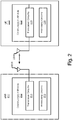
- FIG. 1 schematically illustrates a wireless communication system 100 in accordance with various embodiments.
- the wireless communication system 100 includes a backbone network 110, a cellular mobile network 120, and a D2D network 130.
- the backbone network 110 may be a part of computer network infrastructure that interconnects various sub-networks and provides a path for the exchange of information between these sub-networks.
- the backbone network 110 may include Internet backbone 112, which may include the principal data routes between large, strategically interconnected computer networks and core routers on the Internet.
- the cellular mobile network 120 is connected to the backbone network 110.
- the cellular mobile network 120 may include one or more radio access networks, such as a Global System for Mobile Communication (GSM), General Packet Radio Service (GPRS), Universal Mobile Telecommunications System (UMTS), High Speed Packet Access (HSPA), Evolved HSPA (E-HSPA), or Long-Term Evolution (LTE) network.
- GSM Global System for Mobile Communication
- GPRS General Packet Radio Service
- UMTS Universal Mobile Telecommunications System
- High Speed Packet Access HSPA
- E-HSPA Evolved HSPA
- LTE Long-Term Evolution
- a radio access network may include GSM Enhanced Data rates for GSM Evolution (EDGE) Radio Access Network (GERAN), Universal Terrestrial Radio Access Network (UTRAN), or Evolved UTRAN (E-UTRAN).
- EDGE GSM Enhanced Data rates for GSM Evolution
- GERAN Universal Terrestrial Radio Access Network
- E-UTRAN Evolved UTRAN
- Wireless communication technology may rely on various standards and protocols to transmit data between a base station and a wireless communication device.
- Wireless communication system standards and protocols include, for example, the 3GPP LTE; the Institute of Electrical and Electronics Engineers (IEEE) 802.16 standard, which is commonly known to industry groups as worldwide interoperability for microwave access (WiMAX); and the IEEE 802.11 standard, which is commonly known to industry groups as Wi-Fi.
- IEEE Institute of Electrical and Electronics Engineers
- WiMAX worldwide interoperability for microwave access
- Wi-Fi Wi-Fi
- RAN radio access network
- the base station is referred to as an evolved Node B (also commonly denoted as eNodeB, or eNB). It communicates with a wireless communication device, known as user equipment (UE).
- UE user equipment
- the cellular mobile network 120 may include eNB 124, RNC and NB 126, mobility management entities (MME) and serving gateways (SGW) 122, and serving GPRS support nodes (SGSN) 128.
- eNB 124 is more intelligent than legacy NB 126, which is used in a 3G network such as a UMTS network.
- radio network controller (RNC) functionality is located in eNB 124 rather than being in a separate RNC entity.
- eNB 124 may connect to another eNB by means of an X2 interface that allows the eNBs to forward or share information.
- the cellular mobile network 120 is an Internet Protocol (IP) based network, wherein interfaces between network entities (e.g., eNB 124 and MME/SGW 122) is based on IP.
- MME/SGW 122 may communicate with eNB 124 over an S1 interface.
- the S1 interface may be similar to the S1 interface as defined in 3GPP TS 36.410 V11.1.0 (2013-09 ) and may support a many-to-many relation between MME/SGW 122 and eNB 124. For example, different operators may simultaneously operate the same eNB in a network sharing setting.
- communication between the eNB 124 and UEs is facilitated via the MME/SGW 122.
- the MME/SGW 122 is configured to manage signaling exchanges, e.g., authentication of the UE 132, or perform other actions associated with establishment of a communication link to establish a connected mode of the UE 132 with the cellular mobile network 120.
- the MME/SGW 122 is responsible for tracking and paging user equipment, e.g., when the UE 132 is in an idle mode.
- the eNB 124 may represent a radio network controller (RNC) configured to communicate with the UEs 132, 134, or 136 (discussed in additional detail below) via a NB.
- RNC radio network controller
- the eNB 124 may represent a base station controller (BSC) configured to communicate with the UEs 132, 134, or 136 via a base transmission station (BTS).
- BSC base station controller
- the UE 132 may access the cellular mobile network 120 via a radio link with one of the base stations, e.g., eNB 124.
- a downlink (DL) transmission is a communication from the eNB 124 to the UE 132.
- An uplink (UL) transmission is a communication from the UE 132 to the eNB 124.
- Only limited numbers of UEs and eNBs are illustrated in Figure 1 for ease of illustration.
- the communication system 100 may include any number of UEs, eNBs, or other servers while practicing suitable embodiments of the present disclosure.
- the cellular mobile network 120 may also include other servers, such as a machine type communication (MTC) server (not shown) to facilitate MTC.
- MTC machine type communication
- the UE 134 is configured to communicate with another machine. Data is transmitted from the UE 134 to another machine or received by the UE 134 from another machine with the need for little or no human interaction.
- the UE 134 is a sensor that is electrically coupled to a wireless transceiver (e.g., the transceiver circuitry 224, discussed below with reference to Figure 2 ), and is configured to communicate, with little or no intervention, with another machine (e.g., another sensor).
- the wireless transceiver of the UE 134 may also be configured to communicate with at least one of a wireless metropolitan area network (WMAN), a wireless local area network (WLAN), or a wireless personal area network (WPAN).
- WMAN wireless metropolitan area network
- WLAN wireless local area network
- WPAN wireless personal area network
- the UE 136 is a mobile communication device, a subscriber station, or another device that is configured to communicate with the cellular mobile network 120, e.g., via the eNB 124, in conformance with an appropriate protocol (e.g., a multiple-input/multiple-output (MIMO) communication scheme).
- an appropriate protocol e.g., a multiple-input/multiple-output (MIMO) communication scheme.
- MIMO multiple-input/multiple-output
- the UEs, 132, 134, and/or 136 is configured to enable D2D functionality for public safety applications, e.g., upon receiving a special System Information Block (SIB) message from eNB 124.
- SIB System Information Block
- UE 132, UE 134, and UE 136 may form a D2D network 130.
- D2D network 130 two UEs in proximity may directly communicate with each other without the assistance of eNB 124 or any other base stations and cellular mobile networks.
- Direct communication between devices is commonly known as device-to-device (D2D) direct communication or peer-to-peer (P2P) communication.
- D2D device-to-device
- P2P peer-to-peer
- D2D operation in the D2D network 130 is non-transparent to the cellular mobile network 120 and may occur on a cellular spectrum (i.e., inband) or unlicensed spectrum (i.e., outband).
- D2D operation in the D2D network 130 is realized in different communication technologies. In some embodiments, short-range technologies, such as Bluetooth or Wi-Fi is used. In some embodiments, D2D operation may reuse licensed LTE spectrum or unlicensed LTE spectrum.
- D2D operation in the D2D network 130 may first include device discovery, whereby UEs are to determine whether they are within range and/or available for D2D operation before establishing a D2D session.
- Proximity detection is assisted by the cellular mobile network 120, is performed at least partially by UEs, or is performed largely by UEs independently.
- D2D discovery is closed D2D discovery or open D2D discovery. Closed D2D discovery may apply to use cases wherein a discoverable device is discovered only by a select set of D2D-enabled discovering devices. For example, only pre-identified or selected devices is allowed to connect, such as devices identified or selected by the cellular mobile network 120, a D2D server (not shown), an application (not shown), or a user (not shown). Thus, for this use case, a discovering device would be assumed to know, in advance, the D2D-enabled devices it wishes to discover in its proximity, including any corresponding identifiers.
- open device discovery considers use cases wherein a discoverable device may want itself to be discovered by any or all D2D-enabled devices in its proximity. From the perspective of the discovering device, open device discovery implies that a discovering device may not be aware of the identity of other D2D enabled devices prior to discovery. Consequently, the device discovery mechanism for open discovery may aim toward discovering as many D2D-enabled devices in its proximity as possible.
- an eNB may have limited control of the discovery process among UEs.
- an eNB may periodically allocate certain discovery resources in the form of D2D discovery regions (e.g., time/frequency resources such as resource blocks or subframes) for UEs to transmit the discovery information.
- the discovery information is in the form of a discovery sequence or discovery packet with payload information.
- D2D operation in the D2D network 130 may improve spectrum utilization, increase network throughput, reduce transmission delay, offload traffic for eNB 124, and alleviate congestion in the cellular mobile network 120.
- D2D operation may have a wide variety of applications.
- D2D network 130 is used for local social networks, content sharing, location-based marketing, service advertisements, mobile-to-mobile applications, etc.
- the D2D network 130 may become a fallback public safety network that may function even when the cellular mobile network 120 becomes unavailable or fails.
- the communication system 100 may use a unified method (further discussed below) to automatically configure all the devices, e.g., UEs 132, 134, and 136, within the area of emergency into a Public Safety mode where all applicable operation modes (e.g. communication) is enabled.
- D2D communication includes only the broadcast of information.
- the Public Safety use case is enabled independent of the underlying standards (e.g., LTE Direct or ProSe) as well as the device configuration status (e.g., idle or connected).
- FIG. 2 is a schematic block diagram illustrating components of an eNB 210 and a UE 220 in a wireless communication environment in accordance with various embodiments.
- the eNB 210 may be similar to, and substantially interchangeable with eNB 124 of Figure 1 .
- the eNB 210 may include one or more antennas 218 and communication module 212.
- transceiver circuitry 214 and processing circuitry 216 within the communication module 212 is coupled with each other as shown.
- the UE 220 may be similar to, and substantially interchangeable with UE 132, 134, or 136 of Figure 1 .
- the UE 220 may include one or more antennas 228 and communication device 222.
- transceiver circuitry 224 and processing circuitry 226 within the communication module 222 is coupled with each other as shown.
- the transceiver circuitry 214 is coupled with the antennas 218 to facilitate over-the-air communication of signals to/from the eNB 210.
- Operations of the transceiver circuitry 214 may include, but are not limited to, filtering, amplifying, storing, modulating, demodulating, transforming, etc.
- the transceiver circuitry 214 is configured to provide various signal processing operations on the signal to the antennas 218 with appropriate characteristics.
- the transceiver circuitry 214 is configured to communicate with UEs that have D2D operation capabilities.
- the transceiver circuitry 214 is configured to receive signals from the antennas 218 for transmission to other components of the eNB 210 and/or for internal processing by the processing circuitry 216.
- the processing circuitry 216 generates System Information Block (SIB) messages to activate one or more public safety functionalities of the UE 220 related to D2D operation.
- SIB System Information Block
- the processing circuitry 216 further transmits configuration and control information relating to public safety to other access nodes over backhaul links, e.g., to further facilitate D2D operation of the UE 220.
- the processing circuitry 216 may generate configuration and control information to UEs of a serving cell, e.g., UE 220.
- the configuration and control information may include, for example, downlink channel information, downlink control information (DCI), radio resource control (RRC) configuration information, etc.
- such configuration and control information includes a SIB message to activate at least one of D2D discovery, D2D communication, or D2D relay functionality of the UE 220.
- the processing circuitry 216 generates different types of SIB messages for UE 220. According to the invention, processing circuitry 216 generates a first-type SIB message for primary notification, followed by a second-type SIB message for secondary notification with configuration information for D2D operation.
- the secondary notification to UE 220 includes information for preferred frequency spectrum for D2D operation and information for D2D synchronization source set-up.
- the secondary notification may further comprise a public safety alert, or a public safety release message.
- the processing circuitry 216 generates aforementioned SIB messages and may send the SIB messages to numerous selected UEs in an alert region, for example, to build the D2D network 130 of Figure 1 .
- communication module 212 may send the first-type SIB message with primary notification via paging.
- a paging message may be used to inform UEs in RRC IDLE as well as in RRC_CONNECTED modes.
- communication module 212 may send the second-type SIB message with secondary notification via Cell Broadcast Service (CBS).
- CBS Cell Broadcast Service
- the communication module 222 is coupled with the antennas 228 to facilitate over-the-air communication of signals between UE 220 and eNB 210 or between UE 220 and another UE.
- the transceiver circuitry 224 is configured to provide various signal processing operations on the signal to the antennas 228 with suitable characteristics.
- operations of the transceiver circuitry 224 may include, but are not limited to, filtering, amplifying, storing, modulating, demodulating, transforming, etc.
- the transceiver circuitry 224 is configured to receive signals from the antennas 218, and then transmit the signals to other components of the UE 220 and/or for internal processing by the processing circuitry 226.
- the processing circuitry 226 may activate the UE 220 into a public safety mode in response to a primary notification in a SIB message received from the eNB 210. Further, the processing circuitry 226 configures the UE 220 for various public safety functions based on D2D operation within the public safety mode.
- the communication module 222 is configured to receive the primary notification in a Paging Type 1 message if the UE 220 is in an RRC_IDLE state. In some embodiments, the communication module 222 is configured to receive the primary notification in a System Information Change Indication (SICI) message if the UE is in an RRC_CONNECTED state. In some embodiments, the processing circuitry 226 may activate, in response to the primary notification, a reception of one or more cell broadcast messages containing one or more secondary notifications with authorization or configuration information for D2D operation. Thus, with the information contained in the secondary notifications, UE 220 is properly configured for D2D operation, such as with preferred spectrums for D2D operation or proper D2D synchronization sources.
- SICI System Information Change Indication
- the processing circuitry 226 may present to the user of the UE 220 an audio or visual warning message.
- the warning notification may show information of a public safety alert contained in the primary notification.
- the warning notification may convey the information about the availability of the Public Safety feature on the UE 220 to the user.
- the warning notification may demonstrate one or more public safety features enabled at the UE 220.
- warning notification is contained in the primary or secondary notification distributed by the eNB 210.
- warning notification is generated locally by the UE 220, for example, based on the received primary notification, and displayed by the UE 220 upon activating one or more Public Safety features.
- the UE 220 may include one or more antennas 228 to concurrently utilize radio resources of multiple respective component carriers.
- the UE 220 may be configured to communicate using Orthogonal Frequency Division Multiple Access (OFDMA) (in, e.g., downlink communications) and/or Single-Carrier Frequency Division Multiple Access (SC-FDMA) (in, e.g., uplink communications).
- OFDMA Orthogonal Frequency Division Multiple Access
- SC-FDMA Single-Carrier Frequency Division Multiple Access
- the UE 220 may use the transceiver circuitry 224 to communicate with another UE via LTE ProSe or LTE Direct.
- communication module 222 is configured to provide communication services for one or more subscriber identity modules (SIMs) (not shown) with which it is coupled.
- SIMs subscriber identity modules
- the SIMs may be removably coupled with the communication module 222.
- the SIMs may be hardware and/or firmware that are permanently coupled with the UE 220.
- the SIMs may include full-size SIMs, mini-SIMs, micro-SIMs, nano-SIMs, embedded SIMs, and/or virtual SIMs.
- the SIMs may be integrated circuits that securely store subscriber identity information such as international mobile subscriber identity (IMSI) and related keys used to identify and authenticate one or more subscribers using the UE 220.
- IMSI international mobile subscriber identity
- Each SIM may be associated with different subscriber identity information and may or may not be associated with different carriers.
- IMSI and related information may be used to facilitate D2D discovery and D2D operation.
- the transceiver circuitry 224 and/or processing circuitry 226 may be included in, for example, radio frequency (RF) circuitry or baseband circuitry as described below with respect to Figure 5 .
- the UE 220 may be, may include, or may be included in a single sensor device, a cellular telephone, a personal computer (PC), a notebook, an ultrabook, a netbook, a smartphone, an ultra mobile PC (UMPC), a handheld mobile device, an universal integrated circuit card (UICC), a personal digital assistant (PDA), a Customer Premise Equipment (CPE), a tablet computing device, or other consumer electronics such as MP3 players, digital cameras, and the like.
- PC personal computer
- UMPC ultrabook
- UICC ultra mobile PC
- UICC universal integrated circuit card
- PDA personal digital assistant
- CPE Customer Premise Equipment
- tablet computing device or other consumer electronics such as MP3 players, digital cameras, and the like.
- the UE may include a mobile station, as defined by IEEE 802.16e (2005 or 802.16m (2009) or some other revision of the IEEE 802.16 standard, or user equipment, as defined by 3GPP LTE Release 8 (2008), Release 9 (2009), Release 10 (2011), Release 12 (under development), or some other revision or release of the 3GPP LTE standards.
- IEEE 802.16e 2005 or 802.16m (2009) or some other revision of the IEEE 802.16 standard
- user equipment as defined by 3GPP LTE Release 8 (2008), Release 9 (2009), Release 10 (2011), Release 12 (under development), or some other revision or release of the 3GPP LTE standards.
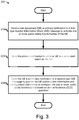
- FIG 3 is a flowchart illustrating a method 300 for enabling D2D functionality for public safety applications in accordance with various embodiments.
- the method 300 is performed by an eNB, e.g., the eNB 210 of Figure 2 or the eNB 124 of Figure 1 .
- the method 300 is a unified method to activate D2D-capable devices within an area of emergency into a Public Safety mode, to form a group of D2D Public Safety users within the area, or even to construct an ad hoc network among D2D-capable devices in view of the emergency.
- the method 300 may be implemented to extend a Public Warning System (PWS) as specified within 3GPP (e.g., in 3GPP TS 22.268 V12.2.0 (2013-06 )), such as Earthquake and Tsunami Warning System (ETWS), Commercial Mobile Alert System (CMAS), or other regional systems like Korean Public Alert System (KPAS) or EU-ALERT.
- PWS Public Warning System
- the method 300 may be a reliable choice to enable Public Safety usages on any cellular-enabled devices regardless of their individually implemented standards because the support of the PWS likely is available in any cellular-enabled devices due to such requirement on a national regulatory basis.
- the method 300 may piggyback onto the PWS to provide information to the users before the emergency occurs or while the cellular network is still reliable before e.g., being destroyed by a tsunami or a hurricane. Therefore, a system implementing the method 300 may provide the users the connectivity means for later, e.g., after the emergency occurs and/or even after the communication infrastructure is disabled or destroyed.
- the method 300 includes, at 310, sending a UE (e.g., the UE 134) a primary notification in a first-type SIB message, for example, by eNB 124, to activate one or more public safety functionalities of the UE.
- the primary notification is sent by the processing circuitry 216 of Figure 2 .
- first-type SIB message may be a new SIB for LTE, e.g. System Information Block #17 (SIB#17) for conveying the Primary Notification.
- SIB#17 may contain, but is not limited to, a region-wide or maximum extent alert and information for activating Public Safety functionalities of D2D-enabled devices.
- Public Safety functionalities may include discovery, communication, or relay functionality.
- the first-type SIB message conveying the primary notification is sent to a ProSe/LTE-Direct-enabled UE about a predicted Public Safety incident via paging.
- the paging message containing the primary notification may be used to inform ProSe/LTE-Direct-enabled UEs in the RRC_IDLE status or in the RRC_CONNECTED status about the request to wake up Public-Safety functionality.
- the paging message containing the primary notification is sent to the targeted UEs within four seconds in case the Public Safety incident involves upcoming full or partial damages to the cellular network infrastructure.
- the primary notification may activate all applicable operation modes (e.g., communication) in the UE.
- public safety functionalities is enabled despite pre-configured user, OEM, operator, or company policies associated with a UE.
- the public safety mode is activated independent of the underlying standard (e.g., LTE Direct or ProSe) as well as the device configuration status (e.g., idle or connected).
- the method 300 may further include, at 320, sending the primary notification to another UE (e.g., the UE 136) in a same alert region as the UE (e.g., the UE 134).
- the sending of the primary notification to other UEs is performed by the processing circuitry 216 of Figure 2 .
- the processing circuitry 216 may employ other circuitry, such as transceiver circuitry 214, and/or antennas 218, to effect the transmission of the primary notification.
- SIB#17 may not only notify a UE about an upcoming danger, but also carry information toward the UE that enables a certain set or sub-set of Public Safety functionality based on ProSe, LTE-Direct, or any other D2D standard existing now or in the future, whichever is implemented on the device.
- the underlying different D2D standards may not be enabled in every UE for those Public Safety use cases.
- the method 300 uses a new SIB for LTE, e.g., SIB#17, for conveying the primary notification; therefore, it may ubiquitously enable those D2D-enabled devices regardless of the underlying D2D standards, e.g., regardless of ProSe or LTE-Direct.
- the receiving UEs within the alert region may be enabled to provide Public Safety communication upon the emergency alert distributed through the PWS. Furthermore, these UEs is ready for D2D operation when the emergency appears or even when the cellular network is impaired.
- the method 300 further includes, at 330, sending the UE (e.g., the UE 134) a secondary notification in a second-type SIB message to provide the UE authorization information and configuration information to configure the one or more public safety functionalities based on D2D operation.
- the secondary notification may be sent by the processing circuitry 216 of Figure 2 .
- the processing circuitry 216 may cooperate with the transceiver circuitry 214 to transmit the secondary notification.
- the secondary notification is transmitted on the physical downlink shared channel (PDSCH) as the BCCH can be mapped to the PDSCH
- PDSCH physical downlink shared channel
- SIB#18 another new SIB for LTE, e.g. System Information Block #18 (SIB#18), is used to provide the secondary notification.
- the secondary notification may contain, but is not limited to, authorization for D2D operation or configuration information for D2D operation.
- the secondary notification contains assistance information for preferred spectrum for D2D operation and assistance information for D2D synchronization source set-up.
- the secondary notification may further contain specification of ProSe incident area information, e.g., to direct ad hoc network set-up.
- the secondary notification may further contain a time stamp of the alert or a Public Safety release message.
- the information contents for primary or secondary notifications in GERAN and UTRAN may be the same as for LTE.
- the secondary notifications is sent via Cell Broadcast Service (CBS) that is similar to the CBS described in 3GPP TS 23.041 (e.g., 3GPP TS 23.041 V12.6.0 (2014-06 )) where new, specific message identifications is specified for Public Safety purposes in various embodiments.
- CBS Cell Broadcast Service
- the Paging Type 1 message may be used to send the ProSe/LTE-Direct-Indication to ProSe/LTE-Direct-enabled UEs in RRC_IDLE, and System Information Change Indication or a new, dedicated message to inform UEs in RRC_CONNECTED.
- the ETWS-Indication if the UE receives the ProSe/LTE-Direct-Indication in GERAN or UTRAN, the UE may activate the reception of cell broadcast messages containing the secondary notifications.
- a similar mechanism as for ETWS may be implemented for sending the primary and secondary notifications.
- the ProSe/LTE-Direct-Indication and the primary notification is sent in paging messages, in Application Information messages that is similar to Application Information messages described in 3GPP TS 44.018 (e.g., 3GPP TS 44.018 V12.2.0 (2014-03 )) or Packet Application Information message (e.g., see 3GPP TS 44.060 V12.1.0 (2014-06 )).
- the ProSe/LTE-Direct-Indication and the primary notification is sent in a Paging Type 1 messages, a System Information Change Indication (e.g., see 3GPP TS 25.331 V12.2.0 (2014-06 )), or in a new dedicated RRC message specifically for UEs in connected mode.
- a System Information Change Indication e.g., see 3GPP TS 25.331 V12.2.0 (2014-06 )
- numerous UEs receiving the primary and secondary notifications may start D2D reception and transmission for D2D discovery and communication.
- a device still in network coverage and capable of as well as authorized for Public Safety relaying would set up relay functionality, start synchronization signaling (D2DSS), and recruit further devices for ad hoc networking to prepare for a potential out-of-network coverage emergency case.
- Other ProSe/LTE-Direct-enabled devices may synchronize with the synchronization source (e.g., D2D relay or eNB in reach) and start broadcasting/group-casting, e.g., their position in a destroyed building, or start transmitting D2D discovery pilots. Therefore, rescue teams may find a UE based on its D2D operation, independent of cellular network coverage or cellular network load.
- the Public Safety use case may be disabled by the same means as discussed above when the emergency ceased, e.g., via a Public Safety Release notification message contained in another SIB#17 or SIB#18 message.
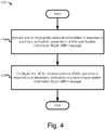
- FIG 4 is a flowchart illustrating another method 400 for enabling D2D functionality for public safety applications in accordance with various embodiments.
- the method 400 is performed by a UE, e.g., the UE 220 of Figure 2 or anyone of the UEs of Figure 1 , such as the UE 132, 134, or 136.
- the method 400 may include, at 410, activating one or more public safety functionalities in response to a primary notification contained in a first-type SIB message.
- the activating of the public safety functionalities may be done by the processing circuitry 226 of Figure 2 .
- the one or more public safety functionalities may be defined in LTE ProSe or LTE Direct.
- a UE receiving the primary notification may enter into a public safety mode to active relevant public safety functionalities independent of whether LTE Direct, ProSe, or another D2D standard is enabled in the UE.
- a UE receiving the primary notification may activate relevant public safety functionalities independent of the UE's connection status, e.g., idle or connected.
- a UE receiving the primary notification may further activate a reception mode to receive cell broadcast messages containing a secondary notification, which may further include D2D configuration information.
- a UE receiving the primary notification may present an audio or visual message to a user of the UE of a public safety alert contained in the primary notification.
- a UE receiving the primary notification may generate notifications informing a user of the public safety functions available on the UE. Therefore, the user of the UE may be made aware of such available public safety functions.
- the method 400 further includes, at 420, configuring the UE for D2D operation, in response to a secondary notification in a received second-type system information block (SIB) message.
- configuring the UE for D2D operation may be done by the processing circuitry 226 of Figure 2 .
- the UE is configured for D2D operation based at least in part on information for the preferred spectrum for D2D operation and information for D2D synchronization source set-up contained in the secondary notification.
- the UE may set up relay functionalities when the UE is capable and authorized for public safety relaying based on the secondary notification.
- the UE may recruit another UE for ad hoc networking.
- the UE may perform device-to-device synchronization signaling (D2DSS) with another UE for a D2D operation session.
- D2DSS device-to-device synchronization signaling
- FIG. 5 illustrates, for one embodiment, an example system 500 comprising radio frequency (RF) circuitry 504, baseband circuitry 508, application circuitry 512, memory/storage 516, display 520, camera 524, sensor 528, and input/output (I/O) interface 532, coupled with each other at least as shown.
- RF radio frequency
- the application circuitry 512 may include circuitry such as, but not limited to, one or more single-core or multi-core processors.
- the processor(s) may include any combination of general-purpose processors and dedicated processors (e.g., graphics processors, application processors, etc.).
- the processors is coupled with memory/storage 516 and configured to execute instructions stored in the memory/storage 516 to enable various applications and/or operating systems running on the system 500.
- the baseband circuitry 508 may include circuitry such as, but not limited to, one or more single-core or multi-core processors.
- the processor(s) may include a baseband processor.
- the baseband circuitry 508 may handle various radio control functions that enable communication with one or more radio networks via the RF circuitry 504.
- the radio control functions may include, but are not limited to, signal modulation, encoding, decoding, radio frequency shifting, etc.
- the baseband circuitry 508 may provide for communication compatible with one or more radio technologies.
- the baseband circuitry 508 may support communication with an E-UTRAN and/or other WMAN, a WLAN, or a WPAN.
- Embodiments in which the baseband circuitry 508 is configured to support radio communications of more than one wireless protocol is referred to as multi-mode baseband circuitry.
- baseband circuitry 508 may include circuitry to operate with signals that are not strictly considered as being in a baseband frequency.
- baseband circuitry 508 may include circuitry to operate with signals having an intermediate frequency, which is between a baseband frequency and a radio frequency.
- the processing circuitry 216 or 226 of Figure 2 is embodied in the application circuitry 512 and/or the baseband circuitry 508.
- RF circuitry 504 may enable communication with wireless networks using modulated electromagnetic radiation through a non-solid medium.
- the RF circuitry 504 may include switches, filters, amplifiers, etc., to facilitate the communication with the wireless network.
- RF circuitry 504 may include circuitry to operate with signals that are not strictly considered as being in a radio frequency.
- RF circuitry 504 may include circuitry to operate with signals having an intermediate frequency, which is between a baseband frequency and a radio frequency.
- the transceiver circuitry 214 or 224 of Figure 2 is embodied in the RF circuitry 504.
- some or all of the constituent components of the baseband circuitry 508, the application circuitry 512, and/or the memory/storage 516 is implemented together on a system on a chip (SOC).
- SOC system on a chip
- Memory/storage 516 is used to load and store data and/or instructions, for example, for system 500.
- Memory/storage 516 for one embodiment may include any combination of suitable volatile memory (e.g., dynamic random access memory (DRAM)) and/or non-volatile memory (e.g., Flash memory).
- suitable volatile memory e.g., dynamic random access memory (DRAM)
- non-volatile memory e.g., Flash memory
- the I/O interface 532 may include one or more user interfaces to enable user interaction with the system 500 and/or peripheral component interfaces to enable peripheral component interaction with the system 500.
- User interfaces may include, but are not limited to, a physical keyboard or keypad, a touchpad, a speaker, a microphone, etc.
- Peripheral component interfaces may include, but are not limited to, a non-volatile memory port, a universal serial bus (USB) port, an audio jack, and a power supply interface.
- USB universal serial bus
- sensor 528 may include one or more sensing devices to determine environmental conditions and/or location information related to the system 500.
- the sensors may include, but are not limited to, a gyro sensor, an accelerometer, a proximity sensor, an ambient light sensor, and a positioning unit.
- the positioning unit may also be part of, or interact with, the baseband circuitry 508 and/or RF circuitry 504 to communicate with components of a positioning network, e.g., a global positioning system (GPS) satellite.
- GPS global positioning system
- the display 520 may include a display, e.g., a liquid crystal display, a touch screen display, etc.
- the camera 524 may include many molded plastic aspheric lens elements made with varying dispersion and refractive indexes. In some embodiments, the camera 524 may include two or more lenses to capture three-dimensional images for stereo photography.
- system 500 is a mobile computing device such as, but not limited to, a laptop computing device, a tablet computing device, a netbook, an ultrabook, a smartphone, etc.
- system 500 may have more or fewer components, and/or different architectures.
- Figure 6 illustrates an article of manufacture 610 having programming instructions, incorporating aspects of the present disclosure, in accordance with various embodiments.
- an article of manufacture is employed to implement various embodiments of the present disclosure.
- the article of manufacture 610 may include a computer-readable non-transitory storage medium 620 where instructions 630 are configured to practice embodiments of or aspects of embodiments of any one of the processes described herein.
- the storage medium 620 may represent a broad range of persistent storage media known in the art, including but not limited to flash memory, dynamic random access memory, static random access memory, an optical disk, a magnetic disk, etc.
- computer-readable storage medium 620 may include one or more computer-readable non-transitory storage media.
- computer-readable storage medium 620 is transitory, such as signals, encoded with instructions 630.
- instructions 630 may enable an apparatus, in response to its execution by the apparatus, to perform various operations described herein.
- storage medium 620 may include instructions 630 configured to cause an apparatus, e.g., eNB 210 in connection with Fig. 2 , to practice some aspects of enabling D2D functionality for public safety applications, e.g., as illustrated in method 300 of Figure 3 , in accordance with embodiments of the present disclosure.
- storage medium 620 may include instructions 630 configured to cause an apparatus, e.g., UE 220 in connection with Fig. 2 , to practice some aspects of enabling D2D functionality for public safety applications, e.g., as illustrated in method 400 of Figure 4 , in accordance with embodiments of the present disclosure.
Landscapes
- Engineering & Computer Science (AREA)
- Computer Networks & Wireless Communication (AREA)
- Signal Processing (AREA)
- Computer Security & Cryptography (AREA)
- Business, Economics & Management (AREA)
- Health & Medical Sciences (AREA)
- Emergency Management (AREA)
- Environmental & Geological Engineering (AREA)
- Public Health (AREA)
- Databases & Information Systems (AREA)
- Mobile Radio Communication Systems (AREA)
Description
- Embodiments of the present disclosure generally relate to the field of wireless communication, and more particularly, to apparatuses and methods for enabling device-to-device (D2D) functionality.
- The background description provided herein is for generally presenting the context of the disclosure. Unless otherwise indicated herein, the materials described in this section are not prior art to the claims in this application and are not admitted to be prior art or suggestions of the prior art, by inclusion in this section.
- D2D applications may provide a scalable and universal framework for connecting proximity peers. There are different technology solutions for D2D applications, e.g., based on WiFi Direct or Near Field Communication (NFC) technology. A special solution that relates to the 3rd Generation Partnership Project (3GPP) is Proximity Services (ProSe) for Commercial and Public Safety use cases as well as Long-Term Evolution (LTE) Direct for Commercial and Public Safety use cases.
- The aforementioned standards may provide a wide range of configurability for User Equipment (UE) devices supporting such standards. For example, it may be possible to configure a UE into a discovery or relay mode. However, the versatile configurability may also enable a UE to limit or entirely stop the communication measures for all related use-cases, including Public Safety use cases.
- On the other hand, the D2D functionality for public safety applications may be disabled due to Original Equipment Manufacturer (OEM) or operator configuration, as well as some special security settings, e.g., where no D2D operation may be allowed for security reasons or on government administration devices.
-
WO 2013/191504 A1 is directed to a method and an apparatus of performing a procedure of forming a Public Safety Group (PSG) for a Proximity-based Service (ProSe). The method comprises receiving first information indicating one or more class identifiers as a part of system information from a network; determining whether any one of one or more configured class identifiers is indicated to be used as a specific class identifier for the PSG formation based on the first information in the system information; and performing a procedure to discover one or more neighboring user equipments for PSG formation using the specific identifier when any one of the one or more configured class identifiers are indicated as the specific class identifier for the PSG formation. -
US 2012/0250501 A1 relates to the processing of signals associated with warding notifications in a wireless communication system. The UE can initiate a certain timer in order not to allow non-emergency calls when warning notification is given in a certain area. In particular, the UE can receive a paging message including warning indication from a network, and starts a delay timer upon receiving the paging message, such as the ETWS and CMAS, if the UE belongs to a delay-tolerant category. The UE performs a random access procedure after the delay timer is expired. -
WO 2009/114848 A1 discloses a wireless transmit receive unit (WTRU) to receive an emergency situation notification. The method and apparatus include the WTRU receiving a paging message with an emergency situation notification, and the WTRU receiving scheduling information in a system information block. -
US 2012/0163235 A1 discloses configuration of a peer-to-peer (P2P) link in a multi-access wireless network. The configuration comprises receiving P2P configuration information from a base station at a UE supporting P2P communication. The first UE communicates directly with a second UE based on the P2P configuration information received from the base station. The first UE may send a configuration request message to the base station, and receive a responsive configuration message with the P2P configuration information from the base station, which messages may be Radio Resource Control (RRC) messages supporting P2P. In the alternative, the P2P configuration information may be provided in a system information block (SIB) broadcast by the base station. - The invention is defined by the subject matter of the independent claims. Advantageous embodiments are subject to the dependent claims.
- Embodiments will be readily understood by the following detailed description in conjunction with the accompanying drawings. To facilitate this description, like reference numerals designate like structural elements. Embodiments are illustrated by way of example and not by way of limitation in the figures of the accompanying drawings.
-
Figure 1 schematically illustrates a wireless communication system in accordance with various embodiments. -
Figure 2 is a schematic block diagram illustrating components of an enhanced node B (eNB) and a UE in the wireless communication system in accordance with various embodiments. -
Figure 3 is a flowchart illustrating a method for enabling D2D functionality for public safety applications in accordance with various embodiments. -
Figure 4 is a flowchart illustrating another method for enabling D2D functionality for public safety applications in accordance with various embodiments. -
Figure 5 is a block diagram of an example computing device that may be used to practice various embodiments described herein. -
Figure 6 illustrates an article of manufacture having programming instructions, incorporating aspects of the present disclosure, in accordance with various embodiments. - In the following detailed description, reference is made to the accompanying drawings, which form a part hereof wherein like numerals designate like parts throughout, and in which is shown by way of illustration embodiments that may be practiced. It is to be understood that other embodiments may be utilized and structural or logical changes may be made.
- Various operations may be described as multiple discrete actions or operations in turn, in a manner that is most helpful in understanding the claimed subject matter. However, the order of description should not be construed as to imply that these operations are necessarily order dependent. In particular, these operations may not be performed in the order of presentation. Operations described may be performed in a different order than the described embodiment. Various additional operations may be performed and/or described operations may be omitted in additional embodiments.
- For the purposes of the present disclosure, the phrase "A and/or B" means (A), (B), or (A and B). For the purposes of the present disclosure, the phrase "A, B, and/or C" means (A), (B), (C), (A and B), (A and C), (B and C), or (A, B, and C). The description may use the phrases "in an embodiment," or "in embodiments," which may each refer to one or more of the same or different embodiments. Furthermore, the terms "comprising," "including," "having," and the like, as used with respect to embodiments of the present disclosure, are synonymous.
- As used herein, the term "circuitry" may refer to, be part of, or include an Application Specific Integrated Circuit (ASIC), an electronic circuit, a processor (shared, dedicated, or group), and/or memory (shared, dedicated, or group) that execute one or more software or firmware programs, a combinational logic circuit, and/or other suitable hardware components that provide the described functionality.
-
Figure 1 schematically illustrates awireless communication system 100 in accordance with various embodiments. Thewireless communication system 100 includes abackbone network 110, a cellularmobile network 120, and aD2D network 130. - The
backbone network 110 may be a part of computer network infrastructure that interconnects various sub-networks and provides a path for the exchange of information between these sub-networks. In various embodiments, thebackbone network 110 may includeInternet backbone 112, which may include the principal data routes between large, strategically interconnected computer networks and core routers on the Internet. - The cellular
mobile network 120 is connected to thebackbone network 110. In various embodiments, the cellularmobile network 120 may include one or more radio access networks, such as a Global System for Mobile Communication (GSM), General Packet Radio Service (GPRS), Universal Mobile Telecommunications System (UMTS), High Speed Packet Access (HSPA), Evolved HSPA (E-HSPA), or Long-Term Evolution (LTE) network. In some embodiments, a radio access network may include GSM Enhanced Data rates for GSM Evolution (EDGE) Radio Access Network (GERAN), Universal Terrestrial Radio Access Network (UTRAN), or Evolved UTRAN (E-UTRAN). The cellularmobile network 120 may operate in accordance with other network technologies in other embodiments. - Mobile communication technology may rely on various standards and protocols to transmit data between a base station and a wireless communication device. Wireless communication system standards and protocols include, for example, the 3GPP LTE; the Institute of Electrical and Electronics Engineers (IEEE) 802.16 standard, which is commonly known to industry groups as worldwide interoperability for microwave access (WiMAX); and the IEEE 802.11 standard, which is commonly known to industry groups as Wi-Fi. In a 3GPP radio access network (RAN), according to LTE, the base station is referred to as an evolved Node B (also commonly denoted as eNodeB, or eNB). It communicates with a wireless communication device, known as user equipment (UE). Although the present disclosure is presented with terminology and examples generally directed toward 3GPP systems and standards, the teaching disclosed herein is applied to any type of wireless network or communication standard.
- In various embodiments, the cellular
mobile network 120 may include eNB 124, RNC and NB 126, mobility management entities (MME) and serving gateways (SGW) 122, and serving GPRS support nodes (SGSN) 128.eNB 124 is more intelligent thanlegacy NB 126, which is used in a 3G network such as a UMTS network. For example, radio network controller (RNC) functionality is located ineNB 124 rather than being in a separate RNC entity. In LTE,eNB 124 may connect to another eNB by means of an X2 interface that allows the eNBs to forward or share information. In some embodiments, the cellularmobile network 120 is an Internet Protocol (IP) based network, wherein interfaces between network entities (e.g.,eNB 124 and MME/SGW 122) is based on IP. In some embodiments, MME/SGW 122 may communicate witheNB 124 over an S1 interface. The S1 interface may be similar to the S1 interface as defined in 3GPP TS 36.410 V11.1.0 (2013-09) and may support a many-to-many relation between MME/SGW 122 andeNB 124. For example, different operators may simultaneously operate the same eNB in a network sharing setting. In some embodiments, communication between theeNB 124 and UEs is facilitated via the MME/SGW 122. The MME/SGW 122 is configured to manage signaling exchanges, e.g., authentication of theUE 132, or perform other actions associated with establishment of a communication link to establish a connected mode of theUE 132 with the cellularmobile network 120. In some embodiments, the MME/SGW 122 is responsible for tracking and paging user equipment, e.g., when theUE 132 is in an idle mode. - For ease of illustration, various descriptions herein are provided to conform to 3GPP in the
communication system 100; however, the subject matter of the present disclosure is not limited in this regard and the embodiments disclosed herein may be advantageously applied to other wired or wireless communication protocols or networks. For example, in an embodiment in which the cellularmobile network 120 includes a UTRAN, theeNB 124 may represent a radio network controller (RNC) configured to communicate with theUEs mobile network 120 includes a GERAN, theeNB 124 may represent a base station controller (BSC) configured to communicate with theUEs - In various embodiments, the
UE 132 may access the cellularmobile network 120 via a radio link with one of the base stations, e.g.,eNB 124. A downlink (DL) transmission is a communication from theeNB 124 to theUE 132. An uplink (UL) transmission is a communication from theUE 132 to theeNB 124. Only limited numbers of UEs and eNBs are illustrated inFigure 1 for ease of illustration. However, thecommunication system 100 may include any number of UEs, eNBs, or other servers while practicing suitable embodiments of the present disclosure. As an example, in some embodiments, the cellularmobile network 120 may also include other servers, such as a machine type communication (MTC) server (not shown) to facilitate MTC. - In some embodiments, the
UE 134 is configured to communicate with another machine. Data is transmitted from theUE 134 to another machine or received by theUE 134 from another machine with the need for little or no human interaction. For example, theUE 134 is a sensor that is electrically coupled to a wireless transceiver (e.g., thetransceiver circuitry 224, discussed below with reference toFigure 2 ), and is configured to communicate, with little or no intervention, with another machine (e.g., another sensor). In some embodiments, the wireless transceiver of theUE 134 may also be configured to communicate with at least one of a wireless metropolitan area network (WMAN), a wireless local area network (WLAN), or a wireless personal area network (WPAN). - In some embodiments, the
UE 136 is a mobile communication device, a subscriber station, or another device that is configured to communicate with the cellularmobile network 120, e.g., via theeNB 124, in conformance with an appropriate protocol (e.g., a multiple-input/multiple-output (MIMO) communication scheme). As discussed in further detail below, the UEs, 132, 134, and/or 136 is configured to enable D2D functionality for public safety applications, e.g., upon receiving a special System Information Block (SIB) message fromeNB 124. - In various embodiments,
UE 132,UE 134, andUE 136 may form aD2D network 130. In theD2D network 130, two UEs in proximity may directly communicate with each other without the assistance ofeNB 124 or any other base stations and cellular mobile networks. Direct communication between devices is commonly known as device-to-device (D2D) direct communication or peer-to-peer (P2P) communication. - D2D operation in the
D2D network 130 is non-transparent to the cellularmobile network 120 and may occur on a cellular spectrum (i.e., inband) or unlicensed spectrum (i.e., outband). D2D operation in theD2D network 130 is realized in different communication technologies. In some embodiments, short-range technologies, such as Bluetooth or Wi-Fi is used. In some embodiments, D2D operation may reuse licensed LTE spectrum or unlicensed LTE spectrum. - In various embodiments, D2D operation in the
D2D network 130 may first include device discovery, whereby UEs are to determine whether they are within range and/or available for D2D operation before establishing a D2D session. Proximity detection is assisted by the cellularmobile network 120, is performed at least partially by UEs, or is performed largely by UEs independently. - In various embodiments, D2D discovery is closed D2D discovery or open D2D discovery. Closed D2D discovery may apply to use cases wherein a discoverable device is discovered only by a select set of D2D-enabled discovering devices. For example, only pre-identified or selected devices is allowed to connect, such as devices identified or selected by the cellular
mobile network 120, a D2D server (not shown), an application (not shown), or a user (not shown). Thus, for this use case, a discovering device would be assumed to know, in advance, the D2D-enabled devices it wishes to discover in its proximity, including any corresponding identifiers. - On the other hand, open device discovery considers use cases wherein a discoverable device may want itself to be discovered by any or all D2D-enabled devices in its proximity. From the perspective of the discovering device, open device discovery implies that a discovering device may not be aware of the identity of other D2D enabled devices prior to discovery. Consequently, the device discovery mechanism for open discovery may aim toward discovering as many D2D-enabled devices in its proximity as possible.
- In certain situations, such as for open D2D discovery using licensed resources, an eNB may have limited control of the discovery process among UEs. In particular, an eNB may periodically allocate certain discovery resources in the form of D2D discovery regions (e.g., time/frequency resources such as resource blocks or subframes) for UEs to transmit the discovery information. The discovery information is in the form of a discovery sequence or discovery packet with payload information.
- In various embodiments, D2D operation in the
D2D network 130 may improve spectrum utilization, increase network throughput, reduce transmission delay, offload traffic foreNB 124, and alleviate congestion in the cellularmobile network 120. In this regard, D2D operation may have a wide variety of applications. For example,D2D network 130 is used for local social networks, content sharing, location-based marketing, service advertisements, mobile-to-mobile applications, etc. Enhanced by the teachings in this disclosure, theD2D network 130 may become a fallback public safety network that may function even when the cellularmobile network 120 becomes unavailable or fails. - In the scope of the Public Safety use cases, correct configuration of the device to operate in a Public Safety mode is crucial in the case of emergencies, at least for the user's safety. In various embodiments, the
communication system 100 may use a unified method (further discussed below) to automatically configure all the devices, e.g.,UEs -
Figure 2 is a schematic block diagram illustrating components of aneNB 210 and aUE 220 in a wireless communication environment in accordance with various embodiments. TheeNB 210 may be similar to, and substantially interchangeable witheNB 124 ofFigure 1 . In embodiments, theeNB 210 may include one ormore antennas 218 andcommunication module 212. In various embodiments,transceiver circuitry 214 andprocessing circuitry 216 within thecommunication module 212 is coupled with each other as shown. Likewise, theUE 220 may be similar to, and substantially interchangeable withUE Figure 1 . In embodiments, theUE 220 may include one ormore antennas 228 andcommunication device 222. In various embodiments,transceiver circuitry 224 andprocessing circuitry 226 within thecommunication module 222 is coupled with each other as shown. - The
transceiver circuitry 214 is coupled with theantennas 218 to facilitate over-the-air communication of signals to/from theeNB 210. Operations of thetransceiver circuitry 214 may include, but are not limited to, filtering, amplifying, storing, modulating, demodulating, transforming, etc. In various embodiments, thetransceiver circuitry 214 is configured to provide various signal processing operations on the signal to theantennas 218 with appropriate characteristics. In some embodiments, thetransceiver circuitry 214 is configured to communicate with UEs that have D2D operation capabilities. - The
transceiver circuitry 214 is configured to receive signals from theantennas 218 for transmission to other components of theeNB 210 and/or for internal processing by theprocessing circuitry 216. Theprocessing circuitry 216 generates System Information Block (SIB) messages to activate one or more public safety functionalities of theUE 220 related to D2D operation. Theprocessing circuitry 216 further transmits configuration and control information relating to public safety to other access nodes over backhaul links, e.g., to further facilitate D2D operation of theUE 220. - The
processing circuitry 216 may generate configuration and control information to UEs of a serving cell, e.g.,UE 220. The configuration and control information may include, for example, downlink channel information, downlink control information (DCI), radio resource control (RRC) configuration information, etc. In some embodiments, such configuration and control information includes a SIB message to activate at least one of D2D discovery, D2D communication, or D2D relay functionality of theUE 220. In various embodiments, theprocessing circuitry 216 generates different types of SIB messages forUE 220. According to the invention,processing circuitry 216 generates a first-type SIB message for primary notification, followed by a second-type SIB message for secondary notification with configuration information for D2D operation. The secondary notification toUE 220 includes information for preferred frequency spectrum for D2D operation and information for D2D synchronization source set-up. The secondary notification may further comprise a public safety alert, or a public safety release message. - The
processing circuitry 216 generates aforementioned SIB messages and may send the SIB messages to numerous selected UEs in an alert region, for example, to build theD2D network 130 ofFigure 1 . In some embodiments,communication module 212 may send the first-type SIB message with primary notification via paging. A paging message may be used to inform UEs in RRC IDLE as well as in RRC_CONNECTED modes. In some embodiments,communication module 212 may send the second-type SIB message with secondary notification via Cell Broadcast Service (CBS). - Similar to the
communication module 212, thecommunication module 222 is coupled with theantennas 228 to facilitate over-the-air communication of signals betweenUE 220 andeNB 210 or betweenUE 220 and another UE. For example, thetransceiver circuitry 224 is configured to provide various signal processing operations on the signal to theantennas 228 with suitable characteristics. In various embodiments, operations of thetransceiver circuitry 224 may include, but are not limited to, filtering, amplifying, storing, modulating, demodulating, transforming, etc. - The
transceiver circuitry 224 is configured to receive signals from theantennas 218, and then transmit the signals to other components of theUE 220 and/or for internal processing by theprocessing circuitry 226. Theprocessing circuitry 226 may activate theUE 220 into a public safety mode in response to a primary notification in a SIB message received from theeNB 210. Further, theprocessing circuitry 226 configures theUE 220 for various public safety functions based on D2D operation within the public safety mode. - In some embodiments, the
communication module 222 is configured to receive the primary notification in a Paging Type 1 message if theUE 220 is in an RRC_IDLE state. In some embodiments, thecommunication module 222 is configured to receive the primary notification in a System Information Change Indication (SICI) message if the UE is in an RRC_CONNECTED state. In some embodiments, theprocessing circuitry 226 may activate, in response to the primary notification, a reception of one or more cell broadcast messages containing one or more secondary notifications with authorization or configuration information for D2D operation. Thus, with the information contained in the secondary notifications,UE 220 is properly configured for D2D operation, such as with preferred spectrums for D2D operation or proper D2D synchronization sources. - In some embodiments, in response to the primary notification, the
processing circuitry 226 may present to the user of theUE 220 an audio or visual warning message. As an example, the warning notification may show information of a public safety alert contained in the primary notification. As another example, the warning notification may convey the information about the availability of the Public Safety feature on theUE 220 to the user. As yet another example, the warning notification may demonstrate one or more public safety features enabled at theUE 220. - Therefore, the user would be informed about the communication means with other users in the emergency area even if the user were previously not aware of such capability on the device. In some embodiments, such warning notification is contained in the primary or secondary notification distributed by the
eNB 210. In other embodiments, such warning notification is generated locally by theUE 220, for example, based on the received primary notification, and displayed by theUE 220 upon activating one or more Public Safety features. - In some embodiments, the
UE 220 may include one ormore antennas 228 to concurrently utilize radio resources of multiple respective component carriers. For example, theUE 220 may be configured to communicate using Orthogonal Frequency Division Multiple Access (OFDMA) (in, e.g., downlink communications) and/or Single-Carrier Frequency Division Multiple Access (SC-FDMA) (in, e.g., uplink communications). In some embodiments, theUE 220 may use thetransceiver circuitry 224 to communicate with another UE via LTE ProSe or LTE Direct. - In some embodiments,
communication module 222 is configured to provide communication services for one or more subscriber identity modules (SIMs) (not shown) with which it is coupled. In some embodiments, the SIMs may be removably coupled with thecommunication module 222. In other embodiments, the SIMs may be hardware and/or firmware that are permanently coupled with theUE 220. In various embodiments, the SIMs may include full-size SIMs, mini-SIMs, micro-SIMs, nano-SIMs, embedded SIMs, and/or virtual SIMs. - The SIMs may be integrated circuits that securely store subscriber identity information such as international mobile subscriber identity (IMSI) and related keys used to identify and authenticate one or more subscribers using the
UE 220. Each SIM may be associated with different subscriber identity information and may or may not be associated with different carriers. In various embodiments, IMSI and related information may be used to facilitate D2D discovery and D2D operation. - Some or all of the
transceiver circuitry 224 and/orprocessing circuitry 226 may be included in, for example, radio frequency (RF) circuitry or baseband circuitry as described below with respect toFigure 5 . In various embodiments theUE 220 may be, may include, or may be included in a single sensor device, a cellular telephone, a personal computer (PC), a notebook, an ultrabook, a netbook, a smartphone, an ultra mobile PC (UMPC), a handheld mobile device, an universal integrated circuit card (UICC), a personal digital assistant (PDA), a Customer Premise Equipment (CPE), a tablet computing device, or other consumer electronics such as MP3 players, digital cameras, and the like. In some embodiments, the UE may include a mobile station, as defined by IEEE 802.16e (2005 or 802.16m (2009) or some other revision of the IEEE 802.16 standard, or user equipment, as defined by 3GPP LTE Release 8 (2008), Release 9 (2009), Release 10 (2011), Release 12 (under development), or some other revision or release of the 3GPP LTE standards. -
Figure 3 is a flowchart illustrating amethod 300 for enabling D2D functionality for public safety applications in accordance with various embodiments. Themethod 300 is performed by an eNB, e.g., theeNB 210 ofFigure 2 or theeNB 124 ofFigure 1 . In various embodiments, themethod 300 is a unified method to activate D2D-capable devices within an area of emergency into a Public Safety mode, to form a group of D2D Public Safety users within the area, or even to construct an ad hoc network among D2D-capable devices in view of the emergency. - In some embodiments, the
method 300 may be implemented to extend a Public Warning System (PWS) as specified within 3GPP (e.g., in 3GPP TS 22.268 V12.2.0 (2013-06)), such as Earthquake and Tsunami Warning System (ETWS), Commercial Mobile Alert System (CMAS), or other regional systems like Korean Public Alert System (KPAS) or EU-ALERT. Themethod 300 may be a reliable choice to enable Public Safety usages on any cellular-enabled devices regardless of their individually implemented standards because the support of the PWS likely is available in any cellular-enabled devices due to such requirement on a national regulatory basis. - Moreover, the
method 300 may piggyback onto the PWS to provide information to the users before the emergency occurs or while the cellular network is still reliable before e.g., being destroyed by a tsunami or a hurricane. Therefore, a system implementing themethod 300 may provide the users the connectivity means for later, e.g., after the emergency occurs and/or even after the communication infrastructure is disabled or destroyed. - The
method 300 includes, at 310, sending a UE (e.g., the UE 134) a primary notification in a first-type SIB message, for example, byeNB 124, to activate one or more public safety functionalities of the UE. In some embodiments, the primary notification is sent by theprocessing circuitry 216 ofFigure 2 . In some embodiments, first-type SIB message may be a new SIB for LTE, e.g. System Information Block #17 (SIB#17) for conveying the Primary Notification. The SIB#17 may contain, but is not limited to, a region-wide or maximum extent alert and information for activating Public Safety functionalities of D2D-enabled devices. In some embodiments, Public Safety functionalities may include discovery, communication, or relay functionality. - In some embodiments, the first-type SIB message conveying the primary notification is sent to a ProSe/LTE-Direct-enabled UE about a predicted Public Safety incident via paging. The paging message containing the primary notification may be used to inform ProSe/LTE-Direct-enabled UEs in the RRC_IDLE status or in the RRC_CONNECTED status about the request to wake up Public-Safety functionality. In various embodiments, the paging message containing the primary notification is sent to the targeted UEs within four seconds in case the Public Safety incident involves upcoming full or partial damages to the cellular network infrastructure.
- In some embodiments, the primary notification may activate all applicable operation modes (e.g., communication) in the UE. In some embodiments, dependent on regulatory requirements, public safety functionalities is enabled despite pre-configured user, OEM, operator, or company policies associated with a UE. In some embodiments, the public safety mode is activated independent of the underlying standard (e.g., LTE Direct or ProSe) as well as the device configuration status (e.g., idle or connected).
- The
method 300 may further include, at 320, sending the primary notification to another UE (e.g., the UE 136) in a same alert region as the UE (e.g., the UE 134). In some embodiments, the sending of the primary notification to other UEs is performed by theprocessing circuitry 216 ofFigure 2 . Theprocessing circuitry 216 may employ other circuitry, such astransceiver circuitry 214, and/orantennas 218, to effect the transmission of the primary notification. - In embodiments, the functionality of a PWS is extended by this disclosure. For example, SIB#17 may not only notify a UE about an upcoming danger, but also carry information toward the UE that enables a certain set or sub-set of Public Safety functionality based on ProSe, LTE-Direct, or any other D2D standard existing now or in the future, whichever is implemented on the device.
- The underlying different D2D standards may not be enabled in every UE for those Public Safety use cases. The
method 300 uses a new SIB for LTE, e.g., SIB#17, for conveying the primary notification; therefore, it may ubiquitously enable those D2D-enabled devices regardless of the underlying D2D standards, e.g., regardless of ProSe or LTE-Direct. - Furthermore, at 320, as the primary notification may be sent to all addressable UEs in the alert region, the receiving UEs within the alert region may be enabled to provide Public Safety communication upon the emergency alert distributed through the PWS. Furthermore, these UEs is ready for D2D operation when the emergency appears or even when the cellular network is impaired.
- The
method 300 further includes, at 330, sending the UE (e.g., the UE 134) a secondary notification in a second-type SIB message to provide the UE authorization information and configuration information to configure the one or more public safety functionalities based on D2D operation. In some embodiments, the secondary notification may be sent by theprocessing circuitry 216 ofFigure 2 . In some embodiments, theprocessing circuitry 216 may cooperate with thetransceiver circuitry 214 to transmit the secondary notification. In various embodiments, the secondary notification is transmitted on the physical downlink shared channel (PDSCH) as the BCCH can be mapped to the PDSCH - In embodiments, another new SIB for LTE, e.g. System Information Block #18 (SIB#18), is used to provide the secondary notification. In some embodiments, the secondary notification may contain, but is not limited to, authorization for D2D operation or configuration information for D2D operation. According to the invention, the secondary notification contains assistance information for preferred spectrum for D2D operation and assistance information for D2D synchronization source set-up. In some embodiments, the secondary notification may further contain specification of ProSe incident area information, e.g., to direct ad hoc network set-up. Yet in some embodiments, the secondary notification may further contain a time stamp of the alert or a Public Safety release message.
- The information contents for primary or secondary notifications in GERAN and UTRAN may be the same as for LTE. In both GERAN and UTRAN, the secondary notifications is sent via Cell Broadcast Service (CBS) that is similar to the CBS described in 3GPP TS 23.041 (e.g., 3GPP TS 23.041 V12.6.0 (2014-06)) where new, specific message identifications is specified for Public Safety purposes in various embodiments. In UTRAN, the Paging Type 1 message may be used to send the ProSe/LTE-Direct-Indication to ProSe/LTE-Direct-enabled UEs in RRC_IDLE, and System Information Change Indication or a new, dedicated message to inform UEs in RRC_CONNECTED. As for the ETWS-Indication, if the UE receives the ProSe/LTE-Direct-Indication in GERAN or UTRAN, the UE may activate the reception of cell broadcast messages containing the secondary notifications.
- For GERAN/UTRAN, a similar mechanism as for ETWS may be implemented for sending the primary and secondary notifications. As an example, in GERAN, the ProSe/LTE-Direct-Indication and the primary notification is sent in paging messages, in Application Information messages that is similar to Application Information messages described in 3GPP TS 44.018 (e.g., 3GPP TS 44.018 V12.2.0 (2014-03)) or Packet Application Information message (e.g., see 3GPP TS 44.060 V12.1.0 (2014-06)). In UTRAN, the ProSe/LTE-Direct-Indication and the primary notification is sent in a Paging Type 1 messages, a System Information Change Indication (e.g., see 3GPP TS 25.331 V12.2.0 (2014-06)), or in a new dedicated RRC message specifically for UEs in connected mode.
- In various embodiments, numerous UEs receiving the primary and secondary notifications may start D2D reception and transmission for D2D discovery and communication. A device still in network coverage and capable of as well as authorized for Public Safety relaying would set up relay functionality, start synchronization signaling (D2DSS), and recruit further devices for ad hoc networking to prepare for a potential out-of-network coverage emergency case. Other ProSe/LTE-Direct-enabled devices may synchronize with the synchronization source (e.g., D2D relay or eNB in reach) and start broadcasting/group-casting, e.g., their position in a destroyed building, or start transmitting D2D discovery pilots. Therefore, rescue teams may find a UE based on its D2D operation, independent of cellular network coverage or cellular network load.
- Eventually, the Public Safety use case may be disabled by the same means as discussed above when the emergency ceased, e.g., via a Public Safety Release notification message contained in another SIB#17 or SIB#18 message.
-
Figure 4 is a flowchart illustrating anothermethod 400 for enabling D2D functionality for public safety applications in accordance with various embodiments. Themethod 400 is performed by a UE, e.g., theUE 220 ofFigure 2 or anyone of the UEs ofFigure 1 , such as theUE - The
method 400 may include, at 410, activating one or more public safety functionalities in response to a primary notification contained in a first-type SIB message. In some embodiments, the activating of the public safety functionalities may be done by theprocessing circuitry 226 ofFigure 2 . In some embodiments, the one or more public safety functionalities may be defined in LTE ProSe or LTE Direct. In various embodiments, a UE receiving the primary notification may enter into a public safety mode to active relevant public safety functionalities independent of whether LTE Direct, ProSe, or another D2D standard is enabled in the UE. In various embodiments, a UE receiving the primary notification may activate relevant public safety functionalities independent of the UE's connection status, e.g., idle or connected. - In some embodiments, a UE receiving the primary notification may further activate a reception mode to receive cell broadcast messages containing a secondary notification, which may further include D2D configuration information. In some embodiments, a UE receiving the primary notification may present an audio or visual message to a user of the UE of a public safety alert contained in the primary notification. In some embodiments, a UE receiving the primary notification may generate notifications informing a user of the public safety functions available on the UE. Therefore, the user of the UE may be made aware of such available public safety functions.
- The
method 400 further includes, at 420, configuring the UE for D2D operation, in response to a secondary notification in a received second-type system information block (SIB) message. In some embodiments, configuring the UE for D2D operation may be done by theprocessing circuitry 226 ofFigure 2 . In some embodiments, the UE is configured for D2D operation based at least in part on information for the preferred spectrum for D2D operation and information for D2D synchronization source set-up contained in the secondary notification. In some embodiments, the UE may set up relay functionalities when the UE is capable and authorized for public safety relaying based on the secondary notification. In some embodiments, the UE may recruit another UE for ad hoc networking. In some embodiments, the UE may perform device-to-device synchronization signaling (D2DSS) with another UE for a D2D operation session. - The
UE 220 as described in connection withFigure 2 may be implemented into a system using any suitable hardware, firmware, and/or software configured as desired.Figure 5 illustrates, for one embodiment, anexample system 500 comprising radio frequency (RF)circuitry 504,baseband circuitry 508,application circuitry 512, memory/storage 516,display 520,camera 524,sensor 528, and input/output (I/O)interface 532, coupled with each other at least as shown. - The
application circuitry 512 may include circuitry such as, but not limited to, one or more single-core or multi-core processors. The processor(s) may include any combination of general-purpose processors and dedicated processors (e.g., graphics processors, application processors, etc.). The processors is coupled with memory/storage 516 and configured to execute instructions stored in the memory/storage 516 to enable various applications and/or operating systems running on thesystem 500. - The
baseband circuitry 508 may include circuitry such as, but not limited to, one or more single-core or multi-core processors. The processor(s) may include a baseband processor. Thebaseband circuitry 508 may handle various radio control functions that enable communication with one or more radio networks via theRF circuitry 504. The radio control functions may include, but are not limited to, signal modulation, encoding, decoding, radio frequency shifting, etc. In some embodiments, thebaseband circuitry 508 may provide for communication compatible with one or more radio technologies. For example, in some embodiments, thebaseband circuitry 508 may support communication with an E-UTRAN and/or other WMAN, a WLAN, or a WPAN. Embodiments in which thebaseband circuitry 508 is configured to support radio communications of more than one wireless protocol is referred to as multi-mode baseband circuitry. - In various embodiments,
baseband circuitry 508 may include circuitry to operate with signals that are not strictly considered as being in a baseband frequency. For example, in some embodiments,baseband circuitry 508 may include circuitry to operate with signals having an intermediate frequency, which is between a baseband frequency and a radio frequency. - In some embodiments, the
processing circuitry Figure 2 is embodied in theapplication circuitry 512 and/or thebaseband circuitry 508. -
RF circuitry 504 may enable communication with wireless networks using modulated electromagnetic radiation through a non-solid medium. In various embodiments, theRF circuitry 504 may include switches, filters, amplifiers, etc., to facilitate the communication with the wireless network. - In various embodiments,
RF circuitry 504 may include circuitry to operate with signals that are not strictly considered as being in a radio frequency. For example, in some embodiments,RF circuitry 504 may include circuitry to operate with signals having an intermediate frequency, which is between a baseband frequency and a radio frequency. - In some embodiments, the
transceiver circuitry Figure 2 is embodied in theRF circuitry 504. - In some embodiments, some or all of the constituent components of the
baseband circuitry 508, theapplication circuitry 512, and/or the memory/storage 516 is implemented together on a system on a chip (SOC). - Memory/
storage 516 is used to load and store data and/or instructions, for example, forsystem 500. Memory/storage 516 for one embodiment may include any combination of suitable volatile memory (e.g., dynamic random access memory (DRAM)) and/or non-volatile memory (e.g., Flash memory). - In various embodiments, the I/
O interface 532 may include one or more user interfaces to enable user interaction with thesystem 500 and/or peripheral component interfaces to enable peripheral component interaction with thesystem 500. User interfaces may include, but are not limited to, a physical keyboard or keypad, a touchpad, a speaker, a microphone, etc. Peripheral component interfaces may include, but are not limited to, a non-volatile memory port, a universal serial bus (USB) port, an audio jack, and a power supply interface. - In various embodiments,
sensor 528 may include one or more sensing devices to determine environmental conditions and/or location information related to thesystem 500. In some embodiments, the sensors may include, but are not limited to, a gyro sensor, an accelerometer, a proximity sensor, an ambient light sensor, and a positioning unit. The positioning unit may also be part of, or interact with, thebaseband circuitry 508 and/orRF circuitry 504 to communicate with components of a positioning network, e.g., a global positioning system (GPS) satellite. - In various embodiments, the
display 520 may include a display, e.g., a liquid crystal display, a touch screen display, etc. In some embodiments, thecamera 524 may include many molded plastic aspheric lens elements made with varying dispersion and refractive indexes. In some embodiments, thecamera 524 may include two or more lenses to capture three-dimensional images for stereo photography. - In various embodiments, the
system 500 is a mobile computing device such as, but not limited to, a laptop computing device, a tablet computing device, a netbook, an ultrabook, a smartphone, etc. In various embodiments,system 500 may have more or fewer components, and/or different architectures. -
Figure 6 illustrates an article ofmanufacture 610 having programming instructions, incorporating aspects of the present disclosure, in accordance with various embodiments. In various embodiments, an article of manufacture is employed to implement various embodiments of the present disclosure. As shown, the article ofmanufacture 610 may include a computer-readablenon-transitory storage medium 620 where instructions 630 are configured to practice embodiments of or aspects of embodiments of any one of the processes described herein. Thestorage medium 620 may represent a broad range of persistent storage media known in the art, including but not limited to flash memory, dynamic random access memory, static random access memory, an optical disk, a magnetic disk, etc. In embodiments, computer-readable storage medium 620 may include one or more computer-readable non-transitory storage media. In other embodiments, computer-readable storage medium 620 is transitory, such as signals, encoded with instructions 630. - In various embodiments, instructions 630 may enable an apparatus, in response to its execution by the apparatus, to perform various operations described herein. As an example,
storage medium 620 may include instructions 630 configured to cause an apparatus, e.g.,eNB 210 in connection withFig. 2 , to practice some aspects of enabling D2D functionality for public safety applications, e.g., as illustrated inmethod 300 ofFigure 3 , in accordance with embodiments of the present disclosure. As another example,storage medium 620 may include instructions 630 configured to cause an apparatus, e.g.,UE 220 in connection withFig. 2 , to practice some aspects of enabling D2D functionality for public safety applications, e.g., as illustrated inmethod 400 ofFigure 4 , in accordance with embodiments of the present disclosure.
Claims (15)
- An evolved Node B, eNB (124, 210), comprising:processing circuitry (216) configured to generate a first-type System Information Block, SIB, message for primary notification to activate device-to-device, D2D, operation of one or more public safety functionalities of a user equipment (134, 220), and to generate a second-type SIB message for secondary notification including configuration information for D2D operation;transceiver circuitry (214), coupled to the processing circuitry (216), and configured to send the first-type and second-type SIB messages to the user equipment (134, 220);wherein the transceiver circuitry (214) is configured to send the first-type SIB message to the user equipment (134, 220) via paging, if the user equipment (134, 220) is in an RRC_IDLE state.
- The eNB (124, 210) of claim 1, wherein the processing circuitry (216) is configured to use the first-type SIB message to activate at least one of D2D discovery, D2D communication, or D2D relay functionality of the user equipment (134, 220).
- The eNB (124, 210) of claim 1 or 2, wherein the second-type SIB message comprises information related to a preferred frequency spectrum for D2D operation, information for D2D synchronization source set-up, a public safety alert, or a public safety release message.
- The eNB of one of claims 1 to 3, wherein the transceiver circuitry (214) is configured to send the second-type SIB message via Cell Broadcast Service.
- The eNB (124, 210) of one of claims 1 to 4, wherein the transceiver circuitry (214) is configured to send the primary notification in a Paging Type 1 message if the user equipment (134, 220) is in an RRC_IDLE
state, and wherein the transceiver circuitry (214) is configured to send the primary notification in a System Information Change Indication message if the user equipment (134, 220) is in an RRC_CONNECTED state. - The eNB (124, 210) of any one of claims 1-5, wherein the transceiver circuitry (214) is configured to send the first-type SIB message to a plurality of user equipments (132, 132, 136, 220) in an alert region.
- A method, comprising:sending, by an evolved NodeB, eNB (124, 210), a primary notification in a first-type System Information Block, SIB, message to a user equipment (134, 220) to activate one or more public safety functionalities of the user equipment (134, 220); andsending, by the eNB (124, 210), a secondary notification in a second-type SIB message to the user equipment (134, 220) to provide the user equipment (134, 220) configuration information to configure the device-to-device, D2D, operation underlying the one or more public safety functionalities;the primary notification is sent to the user equipment (134, 220) via paging, if the user equipment (134, 220) is in an RRC_IDLE state.
- The method of claim 7, further comprising:
sending the primary notification to another user equipment (132, 136) in a same alert region as the user equipment (134, 220). - The method of claim 7 or 8, wherein the primary notification is to activate at least one of D2D discovery, D2D communication, or D2D relay functionality of the user equipment (134, 220).
- The method of one of claims 7 to 9, wherein the secondary notification comprises information for preferred spectrum for D2D operation and information for D2D synchronization source set-up.
- The method of one of claims 7 to 10, wherein the secondary notification is sent to the user equipment (134, 220) via Cell Broadcast Service.
- The method of any one of claims 7-11, wherein the one or more public safety functionalities comprises a subset of Long-Term Evolution, LTE, Proximity Services, ProSe, or LTE direct public safety functionalities.
- A user equipment (134, 220), comprising:a transceiver circuitry (224) configured to receive, from an evolved NodeB, eNB (124, 210), a first-type System Information Block, SIB, message for primary notification to activate device-to-device, D2D, operation of one or more public safety functionalities of a user equipment (134, 220), and to receive, from the eNB (124, 210), a second-type SIB message for secondary notification including configuration information for D2D operation; andprocessing circuitry (226), connected to the transceiver circuitry (224), wherein the processing circuitry (226) is configured to activate the user equipment (134, 220) into a public safety mode in response to the primary notification; andconfigure the user equipment (134, 220) for one or more public safety functionalities based on the configuration information contained in the secondary notification;wherein the transceiver circuitry (214) is configured to receive the first-type SIB message via paging, if the user equipment (134, 220) is in an RRC_IDLE state; andwherein the processing circuitry (226) is configured to activate, in response to the primary notification, a reception of said second-type SIB message by the transceiver circuitry (224).
- The user equipment (134, 220) of claim 13, wherein the transceiver circuitry (224) is configured to receive the primary notification in a Paging Type 1 message if the user equipment (134, 220) is in an RRC_IDLE state, and wherein the transceiver circuitry (224) is configured to receive the primary notification in a System Information Change Indication message if the user equipment (134, 220) is in an RRC_CONNECTED state.
- One or more non-transitory computer-readable media having instructions that, when executed by one or more processors of a user equipment (134, 220), cause the user equipment (134, 220) to:receive a first-type System Information Block, SIB, message for primary notification to activate device-to-device, D2D, operation of one or more public safety functionalities of a user equipment (134, 220);receive a second-type SIB message for secondary notification including configuration information for D2D operation;activate the user equipment (134, 220) into a public safety mode in response to a primary notification;configure the user equipment (134, 220) for one or more public safety functionalities based on the configuration information contained in the secondary notification;receive the first-type SIB message via paging, if the user equipment (134, 220) is in an RRC_IDLE state; andactivate, in response to the primary notification, a reception of said second-type SIB by the user equipment (134, 220).
Applications Claiming Priority (3)
| Application Number | Priority Date | Filing Date | Title |
|---|---|---|---|
| US201461933858P | 2014-01-30 | 2014-01-30 | |
| US14/497,913 US9674682B2 (en) | 2014-01-30 | 2014-09-26 | Enabling D2D functionality for public safety applications |
| PCT/US2015/013282 WO2015116676A1 (en) | 2014-01-30 | 2015-01-28 | Enabling d2d functionality for public safety applications |
Publications (3)
| Publication Number | Publication Date |
|---|---|
| EP3100522A1 EP3100522A1 (en) | 2016-12-07 |
| EP3100522A4 EP3100522A4 (en) | 2017-08-30 |
| EP3100522B1 true EP3100522B1 (en) | 2019-09-11 |
Family
ID=53680373
Family Applications (1)
| Application Number | Title | Priority Date | Filing Date |
|---|---|---|---|
| EP15743767.4A Active EP3100522B1 (en) | 2014-01-30 | 2015-01-28 | Enabling d2d functionality for public safety applications |
Country Status (6)
| Country | Link |
|---|---|
| US (1) | US9674682B2 (en) |
| EP (1) | EP3100522B1 (en) |
| CN (1) | CN105850187B (en) |
| HK (1) | HK1225901A1 (en) |
| TW (1) | TWI565341B (en) |
| WO (1) | WO2015116676A1 (en) |
Families Citing this family (26)
| Publication number | Priority date | Publication date | Assignee | Title |
|---|---|---|---|---|
| EP2645807A1 (en) * | 2012-03-30 | 2013-10-02 | Motorola Mobility LLC | Apparatus and method for RRC state synchronization in a wireless communication system |
| GB2523328A (en) * | 2014-02-19 | 2015-08-26 | Nec Corp | Communication system |
| WO2015169389A1 (en) * | 2014-05-09 | 2015-11-12 | Nokia Solutions And Networks Oy | Device-to-device transmissions |
| EP3177100A4 (en) * | 2014-07-31 | 2018-05-30 | Sharp Kabushiki Kaisha | Terminal apparatus, control method, and integrated circuit |
| EP3228129B1 (en) * | 2014-12-02 | 2020-04-08 | Telefonaktiebolaget LM Ericsson (publ) | Wake-up for d2d communication |
| CN105208621A (en) * | 2015-08-14 | 2015-12-30 | 宇龙计算机通信科技(深圳)有限公司 | Communication method, terminal and base station |
| CN105050204B (en) * | 2015-08-14 | 2019-06-11 | 宇龙计算机通信科技(深圳)有限公司 | A kind of method of communication, terminal and base station |
| KR102353202B1 (en) * | 2015-11-06 | 2022-01-19 | 삼성전자 주식회사 | Method and apparatus for service enhancement in a communication system supporting public safety network service |
| US10341833B2 (en) | 2015-11-10 | 2019-07-02 | At&T Mobility Ii Llc | Automatic proximity discovery area technique |
| KR102233218B1 (en) * | 2016-01-19 | 2021-03-29 | 삼성전자주식회사 | A method for control at least one device to communicate at a mobile device and the mobile device in a wireless communicaton system |
| US10425450B2 (en) * | 2016-02-27 | 2019-09-24 | Ofinno, Llc | Mission critical communications |
| US10383143B2 (en) * | 2017-03-03 | 2019-08-13 | Samsung Electronics Co., Ltd. | Methods and systems for sidelink operations for proximity based services in multi SIM multi standby user equipment |
| CN110612728A (en) | 2017-05-04 | 2019-12-24 | 黑莓有限公司 | Providing public warning system messages |
| US10810273B2 (en) | 2017-06-13 | 2020-10-20 | Bank Of America Corporation | Auto identification and mapping of functional attributes from visual representation |
| US11206519B2 (en) | 2017-08-18 | 2021-12-21 | Lg Electronics Inc. | Method and apparatus for relay terminal transmitting and receiving signal in D2D wireless communication system |
| WO2019061200A1 (en) * | 2017-09-28 | 2019-04-04 | 华为技术有限公司 | System message acquisition method and device, system message instruction method and device, and user equipment |
| CN108271140B (en) * | 2017-11-13 | 2021-05-04 | 广东电网有限责任公司电力调度控制中心 | D2D double-current wireless network access method suitable for distribution and utilization service |
| US11535377B2 (en) * | 2017-12-22 | 2022-12-27 | Telefonaktiebolaget Lm Ericsson (Publ) | Method performed in an autonomous unmanned aerial vehicle for enabling autonomous emergency assistance for a communication device registered in a regular cellular network, vehicle and device therefore |
| US11019557B2 (en) | 2018-05-10 | 2021-05-25 | Sharp Kabushiki Kaisha | Apparatus and method for acquisition of periodically broadcasted system information in wireless communication |
| AU2019267712B2 (en) * | 2018-05-10 | 2024-05-09 | FG Innovation Company Limited | Apparatus and method for acquisition of periodically broadcasted system information in wireless communications |
| EP3808130A1 (en) * | 2018-06-15 | 2021-04-21 | Sharp Kabushiki Kaisha | Apparatus and method for acquisition of system information in wireless communications |
| US10869259B2 (en) | 2018-06-15 | 2020-12-15 | Sharp Laboratories Of America, Inc. | Apparatus and method for acquisition of system information in wireless communications |
| CN112272961A (en) * | 2018-06-15 | 2021-01-26 | 夏普株式会社 | Apparatus and method for system information acquisition in wireless communication |
| JP6959896B2 (en) * | 2018-06-25 | 2021-11-05 | 本田技研工業株式会社 | Wireless communication system |
| EP4184973A4 (en) * | 2020-08-06 | 2023-08-09 | Huawei Technologies Co., Ltd. | Communication method, apparatus and system |
| US11882511B2 (en) * | 2021-02-26 | 2024-01-23 | Samsung Electronics Co., Ltd. | Method and apparatus for L2 SL-based UE-to-network relay operations in wireless communication network |
Family Cites Families (17)
| Publication number | Priority date | Publication date | Assignee | Title |
|---|---|---|---|---|
| JP5273495B2 (en) * | 2005-12-13 | 2013-08-28 | 独立行政法人産業技術総合研究所 | Cluster film forming apparatus and film forming method, and cluster generating apparatus and generating method |
| US8599802B2 (en) | 2008-03-14 | 2013-12-03 | Interdigital Patent Holdings, Inc. | Method and apparatus to deliver public warning messages |
| KR101202147B1 (en) * | 2008-06-20 | 2012-11-15 | 인터디지탈 패튼 홀딩스, 인크 | Emergency information in system information broadcast |
| US8339249B2 (en) * | 2008-08-04 | 2012-12-25 | Qualcomm Incorporated | Paging and notification mechanism for emergency warning system over cellular networks |
| US9320067B2 (en) | 2008-11-24 | 2016-04-19 | Qualcomm Incorporated | Configuration of user equipment for peer-to-peer communication |
| US20100216421A1 (en) * | 2009-02-20 | 2010-08-26 | Qualcomm Incorporated | Methods and apparatus for providing emergency alerts in a communication network |
| US8837443B2 (en) * | 2010-08-13 | 2014-09-16 | Sharp Kabushiki Kaisha | Reducing congestion in wireless communication networks |
| US8792338B2 (en) * | 2011-03-31 | 2014-07-29 | Lg Electronic Inc. | Method and apparatus for processing signal associated with warning notification in wireless communication system |
| JP5755962B2 (en) * | 2011-07-22 | 2015-07-29 | 富士通株式会社 | COMMUNICATION DEVICE, COMMUNICATION METHOD, AND COMMUNICATION PROGRAM |
| US9648653B2 (en) | 2011-12-20 | 2017-05-09 | Lg Electronics Inc. | User equipment-initiated control method and apparatus for providing proximity service |
| US8756669B2 (en) | 2012-06-20 | 2014-06-17 | Futurewei Technologies, Inc. | Security mode for mobile communications devices |
| WO2013191504A1 (en) * | 2012-06-21 | 2013-12-27 | Lg Electronics Inc. | Method and apparatus of providing a proximity-based service |
| US8849203B2 (en) * | 2012-06-27 | 2014-09-30 | Alcatel Lucent | Discovering proximity devices in broadband networks |
| WO2014007574A1 (en) | 2012-07-05 | 2014-01-09 | Lg Electronics Inc. | Method and apparatus of providing a proximity-based service for public safety |
| EP2893648A4 (en) * | 2012-09-04 | 2016-04-27 | Lg Electronics Inc | Method and apparatus of providing a proximity-based service for public safety with one or more user equipments out of the cellular network coverage |
| CN104066112A (en) * | 2013-03-21 | 2014-09-24 | 中兴通讯股份有限公司 | Inter-terminal device-to-device communication method and system |
| US9037145B2 (en) * | 2013-06-28 | 2015-05-19 | Motorola Solutions, Inc. | Method and apparatus for maintaining priority and quality of service across multi-user devices |
-
2014
- 2014-09-26 US US14/497,913 patent/US9674682B2/en active Active
-
2015
- 2015-01-28 TW TW104102889A patent/TWI565341B/en not_active IP Right Cessation
- 2015-01-28 CN CN201580003198.1A patent/CN105850187B/en active Active
- 2015-01-28 EP EP15743767.4A patent/EP3100522B1/en active Active
- 2015-01-28 WO PCT/US2015/013282 patent/WO2015116676A1/en active Application Filing
-
2016
- 2016-12-12 HK HK16114110A patent/HK1225901A1/en unknown
Non-Patent Citations (1)
| Title |
|---|
| ERICSSON: "Synchronization Signals and Channel Design for D2D Discovery and Communication", vol. RAN WG1, no. San Francisco, USA; 20131111 - 20131115, 13 November 2013 (2013-11-13), XP050751320, Retrieved from the Internet <URL:http://www.3gpp.org/ftp/tsg_ran/WG1_RL1/TSGR1_75/Docs/> [retrieved on 20131113] * |
Also Published As
| Publication number | Publication date |
|---|---|
| EP3100522A1 (en) | 2016-12-07 |
| EP3100522A4 (en) | 2017-08-30 |
| TW201543921A (en) | 2015-11-16 |
| US20150215757A1 (en) | 2015-07-30 |
| CN105850187A (en) | 2016-08-10 |
| TWI565341B (en) | 2017-01-01 |
| HK1225901A1 (en) | 2017-09-15 |
| US9674682B2 (en) | 2017-06-06 |
| WO2015116676A1 (en) | 2015-08-06 |
| CN105850187B (en) | 2019-09-17 |
Similar Documents
| Publication | Publication Date | Title |
|---|---|---|
| EP3100522B1 (en) | Enabling d2d functionality for public safety applications | |
| US9992806B2 (en) | Public safety discovery and communication using a UE-to-UE relay | |
| US10791551B2 (en) | Construction of transmission patterns for D2D communication | |
| US9386617B2 (en) | Discovery and operation of hybrid wireless wide area and wireless local area networks | |
| US20200120728A1 (en) | Radio Resource Control Connection Establishment | |
| CN107005916B (en) | Network node, user equipment and apparatus supporting D2D communication | |
| EP2810486B1 (en) | Permitting direct mode communications for public safety only in certain geographical areas | |
| CN113853809B (en) | UE, network node for handling UE category information | |
| GB2506886A (en) | A cellular communications system supporting local area cells and device-to-device communications | |
| WO2023130870A1 (en) | Method and apparatus for relay communication | |
| Sharmila et al. | Design of Side Link Protocol for D2D Communications in VANETs using LTE-A | |
| CN117545023A (en) | Communication method, communication device, and communication system |
Legal Events
| Date | Code | Title | Description |
|---|---|---|---|
| PUAI | Public reference made under article 153(3) epc to a published international application that has entered the european phase |
Free format text: ORIGINAL CODE: 0009012 |
|
| STAA | Information on the status of an ep patent application or granted ep patent |
Free format text: STATUS: REQUEST FOR EXAMINATION WAS MADE |
|
| 17P | Request for examination filed |
Effective date: 20160610 |
|
| AK | Designated contracting states |
Kind code of ref document: A1 Designated state(s): AL AT BE BG CH CY CZ DE DK EE ES FI FR GB GR HR HU IE IS IT LI LT LU LV MC MK MT NL NO PL PT RO RS SE SI SK SM TR |
|
| AX | Request for extension of the european patent |
Extension state: BA ME |
|
| DAX | Request for extension of the european patent (deleted) | ||
| A4 | Supplementary search report drawn up and despatched |
Effective date: 20170802 |
|
| RIC1 | Information provided on ipc code assigned before grant |
Ipc: H04W 88/02 20090101ALI20170727BHEP Ipc: H04W 8/00 20090101ALI20170727BHEP Ipc: H04W 68/00 20090101ALI20170727BHEP Ipc: H04W 88/08 20090101ALI20170727BHEP Ipc: H04W 48/08 20090101AFI20170727BHEP |
|
| STAA | Information on the status of an ep patent application or granted ep patent |
Free format text: STATUS: EXAMINATION IS IN PROGRESS |
|
| 17Q | First examination report despatched |
Effective date: 20180404 |
|
| GRAP | Despatch of communication of intention to grant a patent |
Free format text: ORIGINAL CODE: EPIDOSNIGR1 |
|
| STAA | Information on the status of an ep patent application or granted ep patent |
Free format text: STATUS: GRANT OF PATENT IS INTENDED |
|
| INTG | Intention to grant announced |
Effective date: 20190430 |
|
| GRAS | Grant fee paid |
Free format text: ORIGINAL CODE: EPIDOSNIGR3 |
|
| GRAA | (expected) grant |
Free format text: ORIGINAL CODE: 0009210 |
|
| STAA | Information on the status of an ep patent application or granted ep patent |
Free format text: STATUS: THE PATENT HAS BEEN GRANTED |
|
| AK | Designated contracting states |
Kind code of ref document: B1 Designated state(s): AL AT BE BG CH CY CZ DE DK EE ES FI FR GB GR HR HU IE IS IT LI LT LU LV MC MK MT NL NO PL PT RO RS SE SI SK SM TR |
|
| REG | Reference to a national code |
Ref country code: GB Ref legal event code: FG4D |
|
| REG | Reference to a national code |
Ref country code: CH Ref legal event code: EP |
|
| REG | Reference to a national code |
Ref country code: AT Ref legal event code: REF Ref document number: 1180109 Country of ref document: AT Kind code of ref document: T Effective date: 20190915 |
|
| REG | Reference to a national code |
Ref country code: DE Ref legal event code: R096 Ref document number: 602015037800 Country of ref document: DE |
|
| REG | Reference to a national code |
Ref country code: IE Ref legal event code: FG4D |
|
| REG | Reference to a national code |
Ref country code: NL Ref legal event code: FP |
|
| REG | Reference to a national code |
Ref country code: LT Ref legal event code: MG4D |
|
| PG25 | Lapsed in a contracting state [announced via postgrant information from national office to epo] |
Ref country code: FI Free format text: LAPSE BECAUSE OF FAILURE TO SUBMIT A TRANSLATION OF THE DESCRIPTION OR TO PAY THE FEE WITHIN THE PRESCRIBED TIME-LIMIT Effective date: 20190911 Ref country code: BG Free format text: LAPSE BECAUSE OF FAILURE TO SUBMIT A TRANSLATION OF THE DESCRIPTION OR TO PAY THE FEE WITHIN THE PRESCRIBED TIME-LIMIT Effective date: 20191211 Ref country code: SE Free format text: LAPSE BECAUSE OF FAILURE TO SUBMIT A TRANSLATION OF THE DESCRIPTION OR TO PAY THE FEE WITHIN THE PRESCRIBED TIME-LIMIT Effective date: 20190911 Ref country code: NO Free format text: LAPSE BECAUSE OF FAILURE TO SUBMIT A TRANSLATION OF THE DESCRIPTION OR TO PAY THE FEE WITHIN THE PRESCRIBED TIME-LIMIT Effective date: 20191211 Ref country code: HR Free format text: LAPSE BECAUSE OF FAILURE TO SUBMIT A TRANSLATION OF THE DESCRIPTION OR TO PAY THE FEE WITHIN THE PRESCRIBED TIME-LIMIT Effective date: 20190911 Ref country code: LT Free format text: LAPSE BECAUSE OF FAILURE TO SUBMIT A TRANSLATION OF THE DESCRIPTION OR TO PAY THE FEE WITHIN THE PRESCRIBED TIME-LIMIT Effective date: 20190911 |
|
| PG25 | Lapsed in a contracting state [announced via postgrant information from national office to epo] |
Ref country code: AL Free format text: LAPSE BECAUSE OF FAILURE TO SUBMIT A TRANSLATION OF THE DESCRIPTION OR TO PAY THE FEE WITHIN THE PRESCRIBED TIME-LIMIT Effective date: 20190911 Ref country code: LV Free format text: LAPSE BECAUSE OF FAILURE TO SUBMIT A TRANSLATION OF THE DESCRIPTION OR TO PAY THE FEE WITHIN THE PRESCRIBED TIME-LIMIT Effective date: 20190911 Ref country code: ES Free format text: LAPSE BECAUSE OF FAILURE TO SUBMIT A TRANSLATION OF THE DESCRIPTION OR TO PAY THE FEE WITHIN THE PRESCRIBED TIME-LIMIT Effective date: 20190911 Ref country code: RS Free format text: LAPSE BECAUSE OF FAILURE TO SUBMIT A TRANSLATION OF THE DESCRIPTION OR TO PAY THE FEE WITHIN THE PRESCRIBED TIME-LIMIT Effective date: 20190911 Ref country code: GR Free format text: LAPSE BECAUSE OF FAILURE TO SUBMIT A TRANSLATION OF THE DESCRIPTION OR TO PAY THE FEE WITHIN THE PRESCRIBED TIME-LIMIT Effective date: 20191212 |
|
| REG | Reference to a national code |
Ref country code: AT Ref legal event code: MK05 Ref document number: 1180109 Country of ref document: AT Kind code of ref document: T Effective date: 20190911 |
|
| PG25 | Lapsed in a contracting state [announced via postgrant information from national office to epo] |
Ref country code: RO Free format text: LAPSE BECAUSE OF FAILURE TO SUBMIT A TRANSLATION OF THE DESCRIPTION OR TO PAY THE FEE WITHIN THE PRESCRIBED TIME-LIMIT Effective date: 20190911 Ref country code: PT Free format text: LAPSE BECAUSE OF FAILURE TO SUBMIT A TRANSLATION OF THE DESCRIPTION OR TO PAY THE FEE WITHIN THE PRESCRIBED TIME-LIMIT Effective date: 20200113 Ref country code: PL Free format text: LAPSE BECAUSE OF FAILURE TO SUBMIT A TRANSLATION OF THE DESCRIPTION OR TO PAY THE FEE WITHIN THE PRESCRIBED TIME-LIMIT Effective date: 20190911 Ref country code: EE Free format text: LAPSE BECAUSE OF FAILURE TO SUBMIT A TRANSLATION OF THE DESCRIPTION OR TO PAY THE FEE WITHIN THE PRESCRIBED TIME-LIMIT Effective date: 20190911 Ref country code: AT Free format text: LAPSE BECAUSE OF FAILURE TO SUBMIT A TRANSLATION OF THE DESCRIPTION OR TO PAY THE FEE WITHIN THE PRESCRIBED TIME-LIMIT Effective date: 20190911 Ref country code: IT Free format text: LAPSE BECAUSE OF FAILURE TO SUBMIT A TRANSLATION OF THE DESCRIPTION OR TO PAY THE FEE WITHIN THE PRESCRIBED TIME-LIMIT Effective date: 20190911 |
|
| PG25 | Lapsed in a contracting state [announced via postgrant information from national office to epo] |
Ref country code: CZ Free format text: LAPSE BECAUSE OF FAILURE TO SUBMIT A TRANSLATION OF THE DESCRIPTION OR TO PAY THE FEE WITHIN THE PRESCRIBED TIME-LIMIT Effective date: 20190911 Ref country code: SM Free format text: LAPSE BECAUSE OF FAILURE TO SUBMIT A TRANSLATION OF THE DESCRIPTION OR TO PAY THE FEE WITHIN THE PRESCRIBED TIME-LIMIT Effective date: 20190911 Ref country code: IS Free format text: LAPSE BECAUSE OF FAILURE TO SUBMIT A TRANSLATION OF THE DESCRIPTION OR TO PAY THE FEE WITHIN THE PRESCRIBED TIME-LIMIT Effective date: 20200224 Ref country code: SK Free format text: LAPSE BECAUSE OF FAILURE TO SUBMIT A TRANSLATION OF THE DESCRIPTION OR TO PAY THE FEE WITHIN THE PRESCRIBED TIME-LIMIT Effective date: 20190911 |
|
| REG | Reference to a national code |
Ref country code: DE Ref legal event code: R097 Ref document number: 602015037800 Country of ref document: DE |
|
| REG | Reference to a national code |
Ref country code: DE Ref legal event code: R081 Ref document number: 602015037800 Country of ref document: DE Owner name: APPLE INC., CUPERTINO, US Free format text: FORMER OWNER: INTEL IP CORPORATION, SANTA CLARA, CALIF., US Ref country code: DE Ref legal event code: R081 Ref document number: 602015037800 Country of ref document: DE Owner name: APPLE INC., CUPERTINO, US Free format text: FORMER OWNER: INTEL IP CORPORATION, SANTA CLARA, CA, US |
|
| PLBE | No opposition filed within time limit |
Free format text: ORIGINAL CODE: 0009261 |
|
| STAA | Information on the status of an ep patent application or granted ep patent |
Free format text: STATUS: NO OPPOSITION FILED WITHIN TIME LIMIT |
|
| PG2D | Information on lapse in contracting state deleted |
Ref country code: IS |
|
| PG25 | Lapsed in a contracting state [announced via postgrant information from national office to epo] |
Ref country code: DK Free format text: LAPSE BECAUSE OF FAILURE TO SUBMIT A TRANSLATION OF THE DESCRIPTION OR TO PAY THE FEE WITHIN THE PRESCRIBED TIME-LIMIT Effective date: 20190911 Ref country code: IS Free format text: LAPSE BECAUSE OF FAILURE TO SUBMIT A TRANSLATION OF THE DESCRIPTION OR TO PAY THE FEE WITHIN THE PRESCRIBED TIME-LIMIT Effective date: 20200112 |
|
| 26N | No opposition filed |
Effective date: 20200615 |
|
| PG25 | Lapsed in a contracting state [announced via postgrant information from national office to epo] |
Ref country code: MC Free format text: LAPSE BECAUSE OF FAILURE TO SUBMIT A TRANSLATION OF THE DESCRIPTION OR TO PAY THE FEE WITHIN THE PRESCRIBED TIME-LIMIT Effective date: 20190911 Ref country code: SI Free format text: LAPSE BECAUSE OF FAILURE TO SUBMIT A TRANSLATION OF THE DESCRIPTION OR TO PAY THE FEE WITHIN THE PRESCRIBED TIME-LIMIT Effective date: 20190911 |
|
| REG | Reference to a national code |
Ref country code: CH Ref legal event code: PL |
|
| REG | Reference to a national code |
Ref country code: NL Ref legal event code: PD Owner name: APPLE INC.; US Free format text: DETAILS ASSIGNMENT: CHANGE OF OWNER(S), ASSIGNMENT; FORMER OWNER NAME: INTEL IP CORPORATION Effective date: 20200917 |
|
| REG | Reference to a national code |
Ref country code: BE Ref legal event code: MM Effective date: 20200131 |
|
| PG25 | Lapsed in a contracting state [announced via postgrant information from national office to epo] |
Ref country code: LU Free format text: LAPSE BECAUSE OF NON-PAYMENT OF DUE FEES Effective date: 20200128 |
|
| PG25 | Lapsed in a contracting state [announced via postgrant information from national office to epo] |
Ref country code: BE Free format text: LAPSE BECAUSE OF NON-PAYMENT OF DUE FEES Effective date: 20200131 Ref country code: CH Free format text: LAPSE BECAUSE OF NON-PAYMENT OF DUE FEES Effective date: 20200131 Ref country code: LI Free format text: LAPSE BECAUSE OF NON-PAYMENT OF DUE FEES Effective date: 20200131 |
|
| REG | Reference to a national code |
Ref country code: GB Ref legal event code: 732E Free format text: REGISTERED BETWEEN 20201105 AND 20201111 |
|
| PG25 | Lapsed in a contracting state [announced via postgrant information from national office to epo] |
Ref country code: IE Free format text: LAPSE BECAUSE OF NON-PAYMENT OF DUE FEES Effective date: 20200128 |
|
| PG25 | Lapsed in a contracting state [announced via postgrant information from national office to epo] |
Ref country code: TR Free format text: LAPSE BECAUSE OF FAILURE TO SUBMIT A TRANSLATION OF THE DESCRIPTION OR TO PAY THE FEE WITHIN THE PRESCRIBED TIME-LIMIT Effective date: 20190911 Ref country code: MT Free format text: LAPSE BECAUSE OF FAILURE TO SUBMIT A TRANSLATION OF THE DESCRIPTION OR TO PAY THE FEE WITHIN THE PRESCRIBED TIME-LIMIT Effective date: 20190911 Ref country code: CY Free format text: LAPSE BECAUSE OF FAILURE TO SUBMIT A TRANSLATION OF THE DESCRIPTION OR TO PAY THE FEE WITHIN THE PRESCRIBED TIME-LIMIT Effective date: 20190911 |
|
| PG25 | Lapsed in a contracting state [announced via postgrant information from national office to epo] |
Ref country code: MK Free format text: LAPSE BECAUSE OF FAILURE TO SUBMIT A TRANSLATION OF THE DESCRIPTION OR TO PAY THE FEE WITHIN THE PRESCRIBED TIME-LIMIT Effective date: 20190911 |
|
| P01 | Opt-out of the competence of the unified patent court (upc) registered |
Effective date: 20230526 |
|
| PGFP | Annual fee paid to national office [announced via postgrant information from national office to epo] |
Ref country code: GB Payment date: 20231207 Year of fee payment: 10 |
|
| PGFP | Annual fee paid to national office [announced via postgrant information from national office to epo] |
Ref country code: NL Payment date: 20231215 Year of fee payment: 10 Ref country code: FR Payment date: 20231212 Year of fee payment: 10 |
|
| PGFP | Annual fee paid to national office [announced via postgrant information from national office to epo] |
Ref country code: DE Payment date: 20231205 Year of fee payment: 10 |