EP3100356B1 - Digital period divider - Google Patents
Digital period divider Download PDFInfo
- Publication number
- EP3100356B1 EP3100356B1 EP15703421.6A EP15703421A EP3100356B1 EP 3100356 B1 EP3100356 B1 EP 3100356B1 EP 15703421 A EP15703421 A EP 15703421A EP 3100356 B1 EP3100356 B1 EP 3100356B1
- Authority
- EP
- European Patent Office
- Prior art keywords
- signal
- pulse
- input signal
- period
- missing
- Prior art date
- Legal status (The legal status is an assumption and is not a legal conclusion. Google has not performed a legal analysis and makes no representation as to the accuracy of the status listed.)
- Active
Links
Images






Classifications
-
- H—ELECTRICITY
- H03—ELECTRONIC CIRCUITRY
- H03K—PULSE TECHNIQUE
- H03K23/00—Pulse counters comprising counting chains; Frequency dividers comprising counting chains
- H03K23/64—Pulse counters comprising counting chains; Frequency dividers comprising counting chains with a base or radix other than a power of two
-
- G—PHYSICS
- G01—MEASURING; TESTING
- G01D—MEASURING NOT SPECIALLY ADAPTED FOR A SPECIFIC VARIABLE; ARRANGEMENTS FOR MEASURING TWO OR MORE VARIABLES NOT COVERED IN A SINGLE OTHER SUBCLASS; TARIFF METERING APPARATUS; MEASURING OR TESTING NOT OTHERWISE PROVIDED FOR
- G01D5/00—Mechanical means for transferring the output of a sensing member; Means for converting the output of a sensing member to another variable where the form or nature of the sensing member does not constrain the means for converting; Transducers not specially adapted for a specific variable
- G01D5/12—Mechanical means for transferring the output of a sensing member; Means for converting the output of a sensing member to another variable where the form or nature of the sensing member does not constrain the means for converting; Transducers not specially adapted for a specific variable using electric or magnetic means
- G01D5/14—Mechanical means for transferring the output of a sensing member; Means for converting the output of a sensing member to another variable where the form or nature of the sensing member does not constrain the means for converting; Transducers not specially adapted for a specific variable using electric or magnetic means influencing the magnitude of a current or voltage
- G01D5/142—Mechanical means for transferring the output of a sensing member; Means for converting the output of a sensing member to another variable where the form or nature of the sensing member does not constrain the means for converting; Transducers not specially adapted for a specific variable using electric or magnetic means influencing the magnitude of a current or voltage using Hall-effect devices
-
- G—PHYSICS
- G01—MEASURING; TESTING
- G01D—MEASURING NOT SPECIALLY ADAPTED FOR A SPECIFIC VARIABLE; ARRANGEMENTS FOR MEASURING TWO OR MORE VARIABLES NOT COVERED IN A SINGLE OTHER SUBCLASS; TARIFF METERING APPARATUS; MEASURING OR TESTING NOT OTHERWISE PROVIDED FOR
- G01D5/00—Mechanical means for transferring the output of a sensing member; Means for converting the output of a sensing member to another variable where the form or nature of the sensing member does not constrain the means for converting; Transducers not specially adapted for a specific variable
- G01D5/26—Mechanical means for transferring the output of a sensing member; Means for converting the output of a sensing member to another variable where the form or nature of the sensing member does not constrain the means for converting; Transducers not specially adapted for a specific variable characterised by optical transfer means, i.e. using infrared, visible, or ultraviolet light
-
- G—PHYSICS
- G01—MEASURING; TESTING
- G01P—MEASURING LINEAR OR ANGULAR SPEED, ACCELERATION, DECELERATION, OR SHOCK; INDICATING PRESENCE, ABSENCE, OR DIRECTION, OF MOVEMENT
- G01P3/00—Measuring linear or angular speed; Measuring differences of linear or angular speeds
- G01P3/42—Devices characterised by the use of electric or magnetic means
- G01P3/44—Devices characterised by the use of electric or magnetic means for measuring angular speed
- G01P3/48—Devices characterised by the use of electric or magnetic means for measuring angular speed by measuring frequency of generated current or voltage
- G01P3/481—Devices characterised by the use of electric or magnetic means for measuring angular speed by measuring frequency of generated current or voltage of pulse signals
-
- G—PHYSICS
- G01—MEASURING; TESTING
- G01P—MEASURING LINEAR OR ANGULAR SPEED, ACCELERATION, DECELERATION, OR SHOCK; INDICATING PRESENCE, ABSENCE, OR DIRECTION, OF MOVEMENT
- G01P3/00—Measuring linear or angular speed; Measuring differences of linear or angular speeds
- G01P3/42—Devices characterised by the use of electric or magnetic means
- G01P3/44—Devices characterised by the use of electric or magnetic means for measuring angular speed
- G01P3/48—Devices characterised by the use of electric or magnetic means for measuring angular speed by measuring frequency of generated current or voltage
- G01P3/481—Devices characterised by the use of electric or magnetic means for measuring angular speed by measuring frequency of generated current or voltage of pulse signals
- G01P3/486—Devices characterised by the use of electric or magnetic means for measuring angular speed by measuring frequency of generated current or voltage of pulse signals delivered by photo-electric detectors
-
- G—PHYSICS
- G01—MEASURING; TESTING
- G01P—MEASURING LINEAR OR ANGULAR SPEED, ACCELERATION, DECELERATION, OR SHOCK; INDICATING PRESENCE, ABSENCE, OR DIRECTION, OF MOVEMENT
- G01P3/00—Measuring linear or angular speed; Measuring differences of linear or angular speeds
- G01P3/42—Devices characterised by the use of electric or magnetic means
- G01P3/44—Devices characterised by the use of electric or magnetic means for measuring angular speed
- G01P3/48—Devices characterised by the use of electric or magnetic means for measuring angular speed by measuring frequency of generated current or voltage
- G01P3/481—Devices characterised by the use of electric or magnetic means for measuring angular speed by measuring frequency of generated current or voltage of pulse signals
- G01P3/488—Devices characterised by the use of electric or magnetic means for measuring angular speed by measuring frequency of generated current or voltage of pulse signals delivered by variable reluctance detectors
-
- G—PHYSICS
- G01—MEASURING; TESTING
- G01P—MEASURING LINEAR OR ANGULAR SPEED, ACCELERATION, DECELERATION, OR SHOCK; INDICATING PRESENCE, ABSENCE, OR DIRECTION, OF MOVEMENT
- G01P3/00—Measuring linear or angular speed; Measuring differences of linear or angular speeds
- G01P3/42—Devices characterised by the use of electric or magnetic means
- G01P3/44—Devices characterised by the use of electric or magnetic means for measuring angular speed
- G01P3/48—Devices characterised by the use of electric or magnetic means for measuring angular speed by measuring frequency of generated current or voltage
- G01P3/481—Devices characterised by the use of electric or magnetic means for measuring angular speed by measuring frequency of generated current or voltage of pulse signals
- G01P3/489—Digital circuits therefor
-
- H—ELECTRICITY
- H02—GENERATION; CONVERSION OR DISTRIBUTION OF ELECTRIC POWER
- H02P—CONTROL OR REGULATION OF ELECTRIC MOTORS, ELECTRIC GENERATORS OR DYNAMO-ELECTRIC CONVERTERS; CONTROLLING TRANSFORMERS, REACTORS OR CHOKE COILS
- H02P23/00—Arrangements or methods for the control of AC motors characterised by a control method other than vector control
- H02P23/22—Controlling the speed digitally using a reference oscillator, a speed proportional pulse rate feedback and a digital comparator
-
- H—ELECTRICITY
- H02—GENERATION; CONVERSION OR DISTRIBUTION OF ELECTRIC POWER
- H02P—CONTROL OR REGULATION OF ELECTRIC MOTORS, ELECTRIC GENERATORS OR DYNAMO-ELECTRIC CONVERTERS; CONTROLLING TRANSFORMERS, REACTORS OR CHOKE COILS
- H02P6/00—Arrangements for controlling synchronous motors or other dynamo-electric motors using electronic commutation dependent on the rotor position; Electronic commutators therefor
- H02P6/14—Electronic commutators
- H02P6/16—Circuit arrangements for detecting position
-
- H—ELECTRICITY
- H03—ELECTRONIC CIRCUITRY
- H03K—PULSE TECHNIQUE
- H03K21/00—Details of pulse counters or frequency dividers
- H03K21/38—Starting, stopping or resetting the counter
-
- G—PHYSICS
- G01—MEASURING; TESTING
- G01D—MEASURING NOT SPECIALLY ADAPTED FOR A SPECIFIC VARIABLE; ARRANGEMENTS FOR MEASURING TWO OR MORE VARIABLES NOT COVERED IN A SINGLE OTHER SUBCLASS; TARIFF METERING APPARATUS; MEASURING OR TESTING NOT OTHERWISE PROVIDED FOR
- G01D5/00—Mechanical means for transferring the output of a sensing member; Means for converting the output of a sensing member to another variable where the form or nature of the sensing member does not constrain the means for converting; Transducers not specially adapted for a specific variable
- G01D5/12—Mechanical means for transferring the output of a sensing member; Means for converting the output of a sensing member to another variable where the form or nature of the sensing member does not constrain the means for converting; Transducers not specially adapted for a specific variable using electric or magnetic means
- G01D5/244—Mechanical means for transferring the output of a sensing member; Means for converting the output of a sensing member to another variable where the form or nature of the sensing member does not constrain the means for converting; Transducers not specially adapted for a specific variable using electric or magnetic means influencing characteristics of pulses or pulse trains; generating pulses or pulse trains
- G01D5/245—Mechanical means for transferring the output of a sensing member; Means for converting the output of a sensing member to another variable where the form or nature of the sensing member does not constrain the means for converting; Transducers not specially adapted for a specific variable using electric or magnetic means influencing characteristics of pulses or pulse trains; generating pulses or pulse trains using a variable number of pulses in a train
- G01D5/2451—Incremental encoders
Definitions
- the present disclosure relates to a digital period divider.
- a period determined by the rotation of a motor needs to be divided into 360 steps wherein each step indicates a rotation of one degree.
- Other signals such a power mains signal frequency of 50 or 60Hz may need a similar processing.
- incoming "rotation" signals may provide one pulse per revolution or multiple pulses per revolution. In the latter case one period may be longer than the rest, for example when a double notched sensor wheel is used or a flywheel, for example, with a missing teeth for indicating a top dead center position.
- US Patent Application Publication US2008/255796 discloses a method and device for measuring rotation speed of rotating equipment.
- German Patent Application Publication DE 26 53 351 discloses a method and arrangement for digital measurement of a velocity.
- US 4 408 290 A discloses a method for determining the acceleration or deceleration of a moving object.
- a digital period divider may be configured to generate a pulse train which divides a typical period/interval into a plurality of pulses and to detect when one interval exceeds a predefined threshold, for example by 50% of a typical measured interval.
- the exception can be identified by a fixed amount of time, for example 40 milliseconds, or by comparison to previously measured intervals.
- a detector emits a series of equally-spaced pulses, except one is missing.
- the missing pulse can be coincident with the "top-dead-center” (TDC) position of the engine rotation, so detection may be tantamount to locating TDC in time.
- TDC top-dead-center
- the detector is incorporated into an angular timer (a.k.a. Digital Period Divider), which provides the timer for measuring the pulse interval.
- angular timer a.k.a. Digital Period Divider
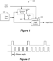
- Figure 1 shows a block diagram of a digital period divider 100 operational to generate an angle clock signal from an input signal.
- the period of the input signal is measured by measurement unit 110 and divided by R by unit 120.
- a counter 130 operating at a higher frequency provided by timebase 140 counts out the angle duration.
- a user can select the angle parameter of the angle clock output signal.
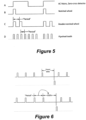
- Figure 2 shows associated timing diagram wherein the top signal represents pulses received that represent a full rotation.
- the bottom signal represents the angle clock, for example here a division by 90° has been chosen.
- the signal period is measured with a fast clock provided by a time base 140 as shown in Figure 1 . Then, the measurement count is divided by a number of angles/revolution and a pulse train of equal intervals is generated.
- a measured period may be represented by R*P, wherein R is the number of angles per revolution.
- R is the number of angles per revolution.
- the period is divided into four angle sections each representing 90°.
- Figure 3 also shows a round off error which may depend on the resolution provided by the time base signal.
- Figure 4 shows an associated block diagram of such a period divider.
- the input signal is fed to a counter unit 420 which counts out a pre-scaled period.
- a time base clock is divided by R through divider 410.
- the output signal from counter unit 420 is latched by latch 430.
- a divider 440 receiving the time base clock divides the time base clock by the latched value to generate the output signal.
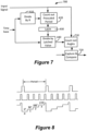
- Figure 5 shows typical output signals provided by various devices that can be used as an input signal of the digital period divider.
- the digital period divider may be programmable to be able to operate with any type of signal as shown in Figure 5 .
- signal A in Figure 5 represents the output of a zero-cross detector coupled with an AC mains signal.
- Signal B may be provided by a notched wheel.
- Signal C may be provided by a double-notched wheel and the signal D may be provided by a toothed flywheel, which has a missing tooth.
- Figure 6 explains how a digital period divider may detect missing pulses to be operable to use the input signals of the third and fourth type as shown in Figure 5 (signals C and D).
- the short intervals are measured and their duration is stored to determine when a long interval occurs. As a hardware compromise, the full period may not be measured. Rather, the period is divided into multiples of the short interval.
- the missing pulse may be detected based on a user defined time. In other words when a predefined number of clock cycles provided by the time base occurs without a reset caused by the input signal, a missing pulse is determined and can be generated as shown in the top of Figure 6 .
- the bottom diagram shows an adaptive measurement according to another embodiment, wherein a period time is determined by previously measured intervals. When a currently measured interval exceeds a predetermined amount, for example 150%, then a missing pulse is determined and can be generated as shown in the bottom half of Figure 6 .
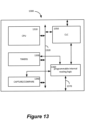
- Figure 7 shows an angle counter 700 according to an embodiment and Figure 8 shows associated input and output signals.
- the angle counter can be configured to count out the angles as discussed above.
- a system as shown in Figure 4 is used with an additional counter unit 710 operable to count out the angles.
- Unit 710 receives the input signal and the output signal of divider 440.
- a capture & compare unit 720 receives the output value from counter unit 710 and a threshold value and generates an output signal as a result of the comparison.
- the capture & compare unit 720 is connected to the output signal that counts out the angles to perform this function.
- Figure 9 shows a block diagram of a digital period divider according to various embodiments.
- a first counter can be formed by two counters 910 and 915 wherein the first counter having P bits concatenates with a second counter 915 having R bits.
- counter 910 provides the most significant bits (MSB) and counter 915 the least significant bits (LSB).
- MSB most significant bits
- LSB least significant bits
- a single counter having P+R bits may be used.
- the overflow of counter 915 clocks the input of counter 910.
- a high frequency clock source 950 is provided, for example a 32 MHz system clock, that provides the count clock input signal for the first counter 910, 915.
- the first counter (or the combined counters 910, 915) have a reset input that receives the unknown frequency X from a frequency source 930.
- a latch 920 having P bits is coupled with counter 910 and therefore with the MSB of the first counter. The unknown frequency triggers the load input of latch 920.
- a second counter 960 having P bits receives the clock signal of the system clock at its count input.
- a comparator 940 is provided that compares the value of the latch 920 and the count value of the second counter 960. If equal, the output of comparator 940 goes high (or low) and may be used to reset the second counter. Also, the output signal of comparator provides the divided clock signal X*2 R .
- a first application 1100 of the period divider 900 shown in Figure 9 is provided.
- an unknown frequency M for example of a motor or other rotary machine 930, is provided to the period divider 1100.
- the circuit 910, 915, 920, 940, 950, and 960 measures the period of rotation, and create a clock 970 that is a fixed multiple of the rotational frequency. Typically, this might be one clock per degree of rotation (that is, times 360), or any convenient multiple.
- the system may be applied to motor systems or to systems like AC power lines with a frequency of 50 or 60 Hz or any other unknown frequency signal.
- the system 1100 requires 2 inputs.
- the unknown frequency input for example motor-pulse, supplies a reference indicating in case of a motor 930 that the motor 930 has turned one revolution.
- a signal can be obtained for example from a Hall-effect sensor or optical interrupter as will be discussed in more detail below.
- Some applications may supply more than one pulse per revolution, and for discussion we take this as M cps (cycles per second).
- the other input is a fixed clock source 950 of any convenient frequency, as long as it is much faster than the expected output signal. For example, a 6000 RPM motor produces an input of 100 cps, and if the machine is set to multiply by 360 (one clock per degree of rotation), the output will be 36000 Hz.
- the clock source of a 32 MHz clock signal 950 is almost 1000x faster, so is adequate.
- the first counter can be actually two counters 915 and 910 according to some embodiments.
- Counter 915 advances with each clock pulse, and is illustrated having R bits for a modulo 2 R count.
- the counter 915 could be any modulo, like 360 or 180, and for discussion we say that counter 915 has modulo R.
- Counter 920 holds P bits and advances every time counter 915 rolls over. Taken together, these counters 915, 910 count the number of clock pulses required for 1 revolution of the motor. With each revolution, the present value of counter 910 is captured in the latch 920, and the entire first counter 915, 910 is reset to zero.
- the latch 920 receives a value which is the total number of clock pulses per revolution divided by R, updated with every cycle of the unknown frequency.
- the size of the counter 910 (value of P) should be chosen to prevent counter overflow knowing M and the clock frequency.
- the second counter 960 advances with each clock pulse, and counts until it reaches a value equal to the latched value.
- the equality logic 940 emits a single pulse and the second counter 960 resets to zero.
- the second counter 960 will do this a total of R times before the latched value changes, and so there will be R equality pulses emitted for each cycle of the unknown signal, for example the motor rotation signal.
- the goal of producing at the output 970 a clock train R times faster than the motor index pulse has been achieved, and the new clock train will change frequency as often as the motor speed changes, albeit one cycle later.
- the latency can be improved by configuring the motor to produce many pulses per revolution, and reducing R proportionately.
- a third counter 1150 a user-value register 1130 for storing a value UV
- an SR latch 1120 This represents logic that is similar to a conventional timer with PWM arrangement, except with the added ability to reset the third counter 1150 with every cycle of the unknown signal from source 930. Since the third counter 1150 is clocked R times per revolution, the counter value will advance from zero to (R-1) within each cycle of the unknown signal. In case the unknown signal is provided by a motor 930, assuming that the motor speed is relatively constant, the counter will be equal to the user value at a rotation angle of 360*(UV /R) degrees after the index pulse. It is highly significant that the user value UV is proportional to degrees, independent of the motor speed.
- UV ultraviolet to represent an angle directly, without the sine, cosine or tangent computations normally required for conversion from the fixed-time measurements of traditional timers and PWMs to angular measurements (or vice versa).
- Figure 12 shows an example with a motor 1210 comprising, for example, a sensor 1220, for example a Hall sensor or optical sensor, capable of generating a pulse with each rotation of the motor shaft.
- a sensor 1220 for example a Hall sensor or optical sensor
- This signal is used as the unknown frequency signal and fed to the period divider of Figure 1 and the additional logic discussed in the embodiment of Figure 11 .
- the reset signal generated by comparator logic 940 is only used to clock counter 1150.
- Flip-flop 1120 comprises output 1140 which provides for a user controlled pulse width modulation signal which can be directly controlled by a value proportional to the rotation degree.
- a flexible timer comparator unit may be provided that allows for the shown arrangements.
- latch 920 may be formed by a capture unit coupled with a first counter and programmable routing may be provided that allows comparing the various values as shown in Figure 12 .
- control registers within the microcontroller may allow to assign inputs of digital comparators to be assigned to timers or capture latches.
- the microcontroller may include programmable logic, such as configurable logic cells that provide for combinatorial logic or various types of flip-flops or latches such as D flip-flop, JK flip-flop or SR latches. Such microcontrollers are manufactured by Applicant for example in the PIC10F32x and PIC1xF150X family.
- FIG. 13 shows an exemplary microcontroller 1300 designed to be able to be programmed to form the functional units as shown in Figure 9 , 11 , and 12 .
- Microcontroller 1300 comprises a central processing unit 1310 connected with an internal bus 1320.
- Various peripherals such as timers 1330, a capture compare unit 1340 and configurable logic cells 1350 may be available and coupled with the internal bus 1320.
- each peripheral may have programmable glue logic that allows to route internal signals to its various inputs, for example, internal or external signals may clock a timer. Two timers may be programmable to form a single concatenated timer, timer values may be coupled with inputs of the capture/compare unit, etc.
- a central programmable internal routing logic 1360 may be provided that allows for the same function namely to assign the various internal or external signals to various inputs/outputs of the peripheral devices.
- the various peripherals may have special function registers that allow the selection of the various input/output signals. Even if a programmable internal routing logic 1360 is provided, such special function registers may be provided to control the unit 1360 wherein the special function registers may be associated with the respective peripheral unit. Thus, the unit 1360 may not be visible to a user as a separate peripheral. Thus, without any additional hardware, a period divider and/or additional logic as discussed above can be formed within the microcontroller 1300 under program control.
- Figure 10 shows an example of a modulo counter with a variable modulo.
- a modulo register 1020 is provided which can be programmed to contain the modulo value.
- a modulo comparator 1010 compares the value of LSB counter 915 with the value of the modulo register 1020 and generates a pulse each time the values are equal. This pulse is used to reset LSB counter 915 and clock MSB counter 910.
- the modulo register 1020 can be, for example, programmed to store a value of 180 or 360 or any other suitable value for dividing the period of the unknown frequency.
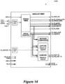
- Figure 14 shows an angular timer 1400 according to the invention for integration within a microcontroller.
- the primary output of the angular timer is the angle clock, at_angle_clock ( Figure 15 , Figure 17 ).
- the angle clock In the basic operating mode, the angle clock has a frequency which is a multiple of signal_in. Other modes provide other features.
- the angle clock may be output on an I/0 pin, or used as the timebase for other device timers.
- the angle clock is used within this module 1400 to generate the angle data value, at_angle[9:0], which can be read by software, used by capture and compare logic, or routed to other system CCP or PWM devices. An interrupt is signaled for each angle clock pulse.
- the module 1400 also measures the period of the input signal. The measured period is compared to a setpoint value (ATxSTPT) to produce an error value (ATxERR).
- module 1400 There are two types of input to module 1400 as shown in Figure 14 : the primary input ATSIG, and the capture logic input signals at_capture[x]. All signal and capture inputs are synchronized to the module clock using edge-detection logic similar to that shown in Figure 16 .
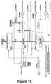
- the missing pulse detector is illustrated in Figure 15 .
- the logic compares the current period counter value with the latched value from the previous cycle (ATxPER), creating a signed difference. When the difference is equal to the ATxMISS register, a missing pulse is declared.
- the at_missed_pulse output is pulsed in all ATMD modes, with a corresponding interrupt.
- every input pulse is considered the "end of period", and a period clock pulse is generated.
- the period clock is generated only after the missing pulse counter and ATxMISS register are equal, and the period latch update is not performed. All other input pulses latch period data.
- the missing pulse delay is measured in time (clock cycles) and not in degrees, because the period counter is used as the reference. Generally speaking, the missing pulse detector only fires once, and then requires a legitimate input edge to reset itself. This is an automatic behavior, because the period counter will max-out at FFFF and not again be equal to ATxMISS.
- the user may enter a setpoint value in register ATxSTPT.
- the setpoint is subtracted from the measured period register ATxPER to produce register ATxERR.
- the angular timer includes two divider chains, and both measure the period of the input signal.
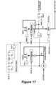
- the second chain ( Figure 17 ) divides clock_in by register ATxPER, which holds the value measured in the previous cycle.
- the resulting clock (clock_in/ATPER) clocks the counter which may be read as ATxANG.
- the angle counter (if theoretically sampled at the end of the period) will be as shown in Equation 2.
- AT ⁇ ANG final F clockIn ⁇ Period signal AT ⁇ PER
- the value in ATxANG may be more or less than ATxRES. Realize also that the ATxANG counter is not required for the generation of at_angle_clock.
- the counter is a module feature that allows for the capture and compare logic, and for the user to monitor instantaneous input angle.
- AR 360 ° ATRES
- ATxANG is cleared to zero at the start of the rotation (that is, at the at_period_clk pulse), and then counts up throughout the cycle, so the value of the counter is linearly related to the instantaneous phase angle as shown in Equation 4.
- a small ATxRES is advantageous for accuracy, but may not meet system requirements.
- the figure-of-merit of the system is defined as the minimum expected ATxPER value, and Equation 1 may be rewritten as Equation 5. It is recommended that for good operation, select clock_in and ATxRES to give FOM > 500.
- the angle clock output is not accurate until the input period has been correctly sampled, which requires at least two complete input cycles (see the example in
- every input edge captures the period duration, ignoring the missing pulse detector, so that a baseline measurement can be established. In other words, when the system is just starting up, every input cycle is captured into ATxPER no matter which ATMD is selected.
- the motor sensor or zero-cross detector provides exactly one pulse for each revolution as shown in Figure 25 . Every ATSIG resets the Period and Angle counters, and the period is measured with each input cycle.
- ATRES is set to produce the required angular resolution. This is the basic timing mode described above.
- the at_missed_pulse output and associated interrupt are active, but have no effect on operation or the other module outputs.
- the motor sensor provides more than one pulse for each revolution.
- the motor sensor pulses twice for each revolution, at a known angular difference.
- the first pulse is assumed as the "top dead center” (TDC) reference, and the 2 nd pulse is used to measure the (partial) period.
- the signal pattern of Figure 29 is typically taken from the flywheel of an internal combustion engine. It is not uncommon to have more than 200 teeth on flywheel, and a pulse appears for all-but-1 tooth gap at the final tooth. The period counter measures the tooth-to-tooth duration except at the gap. The first pulse after the gap signals TDC.
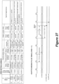
- the missing pulse timeout is one half of the current measured period, as shown in the timing diagram of Figure 27 , and will track changing motor speed. I Note: The value in ATxMISS is not changed.
- the missing pulse timeout is one half of the current measured period, as shown in the timing diagram Figure 27 , and will track changing motor speed. Note: The value in ATxMISS is not changed.
- the primary output of the module is the angle clock, at_angle_clock. Most applications will also require the period clock as a “zero” or “top dead center” reference.
- the module includes the angle counter, which uses both signals. This counter is illustrated in Figure 16 and described above.
- the compare registers of Figure 20 generate an output signal at specified values of ATxANG. Given a required phase angle, use Equation 4 or Equation 6 and solve for the value of ATxANG that represents that angle. Three applications of the compare outputs are illustrated.
- the capture/compare feature can be interpreted as percentage of a cycle. If the period-input signal is applied to a capture input, and the capture polarity is falling edge ( Figure 24 ), the captured value will indicate the duty-cycle of the input signal. The missing pulse detector can indicate if the input has been lost. This application will work regardless of the input frequency, so long as it is relatively constant and not DC. It is also immune to oscillator calibration errors.
- the various embodiments disclosed can be used for commutation of motor windings, generating a pulse of fixed fraction, for example as a type of pulse width modulation, switching something on at a specific fraction such as persistence of vision propeller displays, the timing of output changes during sine wave generation, which, for example, may use a digital-to-analog converter and does not have to use pulse width modulation, etc.
Landscapes
- Physics & Mathematics (AREA)
- General Physics & Mathematics (AREA)
- Engineering & Computer Science (AREA)
- Power Engineering (AREA)
- Control Of Motors That Do Not Use Commutators (AREA)
- Transmission And Conversion Of Sensor Element Output (AREA)
- Control Of Electric Motors In General (AREA)
Description
- The present disclosure relates to a digital period divider.
- In digital applications there is often a need to precisely divide an unknown period. For example a period determined by the rotation of a motor needs to be divided into 360 steps wherein each step indicates a rotation of one degree. Other signals such a power mains signal frequency of 50 or 60Hz may need a similar processing. In particular incoming "rotation" signals may provide one pulse per revolution or multiple pulses per revolution. In the latter case one period may be longer than the rest, for example when a double notched sensor wheel is used or a flywheel, for example, with a missing teeth for indicating a top dead center position.
- US Patent Application Publication
US2008/255796 discloses a method and device for measuring rotation speed of rotating equipment. German Patent Application PublicationDE 26 53 351 discloses a method and arrangement for digital measurement of a velocity. -
US 4 408 290 A discloses a method for determining the acceleration or deceleration of a moving object. - It is therefore an object of the present application to provide for method and arrangement capable of detecting a missing pulse. This and other objects can be achieved by a method and system as defined in the independent claims. Further enhancements are characterized in the dependent claims.
-
Fig. 1 shows a block diagram of a digital period divider; -
Fig. 2 shows respective input and output signals of a digital period divider according to an embodiment; -
Fig. 3 and 4 show a more detailed embodiment of a digital period divider and associated input output signals; -
Fig. 5 shows examples of various input signals for a digital period divider; -
Fig. 6 shows a timing diagram for detection of a missing pulse; -
Fig. 7 and 8 show an angle counter and associated input output signals according to an embodiment. -
Fig. 9 shows a block diagram of a digital period divider; -
Fig. 10 shows an embodiment for a modulo counter which can be used as the LSB counter of the first counter of the period divider. -
Fig. 11 shows a first application embodiment using the period divider ofFig. 9 . -
Fig. 12 shows another application using a period divider ofFig. 9 . -
Fig. 13 shows a microcontroller designed to embody the period divider according to various embodiments. -
Fig. 14 shows a block diagram of an angular timer peripheral, for example, suitable for integration within a microcontroller, according to the invention. -
Fig. 15 shows a block diagram of the period timer and angle counter of the angular timer peripheral ofFig. 14 . -
Fig. 16 shows details of the period timer of the angular timer peripheral ofFig. 14 . -
Fig. 17 shows details of the angle counter of the angular timer peripheral ofFig. 14 . -
Fig. 18 shows a setpoint error feature of the angular timer peripheral ofFig. 14 . -
Fig. 19 shows an interrupt logic of the angular timer peripheral ofFig. 14 . -
Fig. 20 shows compare and capture logic of the angular timer peripheral ofFig. 14 . -
Fig. 21 shows a first COG application, for example in a high speed motor control. -
Fig. 22 shows a second COG application, for example in a fuel injector application. -
Fig. 23 shows a CLC/CWG application, for example, in a motor synchronous strobe light system. -
Fig. 24 shows a pulse duty cycle measurement example, for example for a fan controller application. -
Fig. 25 shows a timing diagram for mode ATMD=00. -
Fig. 26 shows a timing diagram for an example operation with ATXRES=5. -
Fig. 27 shows a table with various operating modes according to register ATMD and a timing diagram for mode ATMD=00. -
Fig. 28 shows a timing diagram for mode ATMD=01. -
Fig. 29 shows a timing diagram for mode ATMD=11. - According to various embodiments, a digital period divider may be configured to generate a pulse train which divides a typical period/interval into a plurality of pulses and to detect when one interval exceeds a predefined threshold, for example by 50% of a typical measured interval. The exception can be identified by a fixed amount of time, for example 40 milliseconds, or by comparison to previously measured intervals.
- For example as mentioned above, with an engine flywheel, a detector emits a series of equally-spaced pulses, except one is missing. The missing pulse can be coincident with the "top-dead-center" (TDC) position of the engine rotation, so detection may be tantamount to locating TDC in time.
- The detector is incorporated into an angular timer (a.k.a. Digital Period Divider), which provides the timer for measuring the pulse interval.
-
Figure 1 shows a block diagram of adigital period divider 100 operational to generate an angle clock signal from an input signal. The period of the input signal is measured bymeasurement unit 110 and divided by R byunit 120. Acounter 130 operating at a higher frequency provided bytimebase 140 counts out the angle duration. A user can select the angle parameter of the angle clock output signal.Figure 2 shows associated timing diagram wherein the top signal represents pulses received that represent a full rotation. The bottom signal represents the angle clock, for example here a division by 90° has been chosen. As stated above, the signal period is measured with a fast clock provided by atime base 140 as shown inFigure 1 . Then, the measurement count is divided by a number of angles/revolution and a pulse train of equal intervals is generated. - According to an implementation as shown in
Figure 3 , a measured period may be represented by R*P, wherein R is the number of angles per revolution. Again, in the example shown inFigure 3 , the period is divided into four angle sections each representing 90°.Figure 3 also shows a round off error which may depend on the resolution provided by the time base signal.Figure 4 shows an associated block diagram of such a period divider. - The input signal is fed to a
counter unit 420 which counts out a pre-scaled period. To this end, a time base clock is divided by R throughdivider 410. The output signal fromcounter unit 420 is latched bylatch 430. Adivider 440 receiving the time base clock divides the time base clock by the latched value to generate the output signal. -
Figure 5 shows typical output signals provided by various devices that can be used as an input signal of the digital period divider. The digital period divider may be programmable to be able to operate with any type of signal as shown inFigure 5 . For example signal A inFigure 5 represents the output of a zero-cross detector coupled with an AC mains signal. Signal B may be provided by a notched wheel. Signal C may be provided by a double-notched wheel and the signal D may be provided by a toothed flywheel, which has a missing tooth. -
Figure 6 explains how a digital period divider may detect missing pulses to be operable to use the input signals of the third and fourth type as shown inFigure 5 (signals C and D). The short intervals are measured and their duration is stored to determine when a long interval occurs. As a hardware compromise, the full period may not be measured. Rather, the period is divided into multiples of the short interval. The missing pulse may be detected based on a user defined time. In other words when a predefined number of clock cycles provided by the time base occurs without a reset caused by the input signal, a missing pulse is determined and can be generated as shown in the top ofFigure 6 . The bottom diagram shows an adaptive measurement according to another embodiment, wherein a period time is determined by previously measured intervals. When a currently measured interval exceeds a predetermined amount, for example 150%, then a missing pulse is determined and can be generated as shown in the bottom half ofFigure 6 . -
Figure 7 shows anangle counter 700 according to an embodiment andFigure 8 shows associated input and output signals. The angle counter can be configured to count out the angles as discussed above. For example, a system as shown inFigure 4 is used with anadditional counter unit 710 operable to count out the angles.Unit 710 receives the input signal and the output signal ofdivider 440. A capture & compareunit 720 receives the output value fromcounter unit 710 and a threshold value and generates an output signal as a result of the comparison. Thus, because it is known when the signal begins each angle is marked and a count value can be generated that is proportional to the angle. As shown inFigure 7 , the capture & compareunit 720 is connected to the output signal that counts out the angles to perform this function. -
Figure 9 shows a block diagram of a digital period divider according to various embodiments. A first counter can be formed by twocounters second counter 915 having R bits. Thus,counter 910 provides the most significant bits (MSB) and counter 915 the least significant bits (LSB). However, according to other embodiments a single counter having P+R bits may be used. In case two counters are used, the overflow ofcounter 915 clocks the input ofcounter 910. A highfrequency clock source 950 is provided, for example a 32 MHz system clock, that provides the count clock input signal for thefirst counter counters 910, 915) have a reset input that receives the unknown frequency X from afrequency source 930. Alatch 920 having P bits is coupled withcounter 910 and therefore with the MSB of the first counter. The unknown frequency triggers the load input oflatch 920. Asecond counter 960 having P bits receives the clock signal of the system clock at its count input. Acomparator 940 is provided that compares the value of thelatch 920 and the count value of thesecond counter 960. If equal, the output ofcomparator 940 goes high (or low) and may be used to reset the second counter. Also, the output signal of comparator provides the divided clock signal X*2R. - It is widely accepted that sine, cosine and tangent computations are necessary when controlling rotary machines, but according to various embodiments a rotation pulse-to-angle conversions is provided.
- Referring to
Figure 11 , afirst application 1100 of theperiod divider 900 shown inFigure 9 is provided. As mentioned above, an unknown frequency M, for example of a motor or otherrotary machine 930, is provided to theperiod divider 1100. Thecircuit clock 970 that is a fixed multiple of the rotational frequency. Typically, this might be one clock per degree of rotation (that is, times 360), or any convenient multiple. The system may be applied to motor systems or to systems like AC power lines with a frequency of 50 or 60 Hz or any other unknown frequency signal. - With reference to the
Figure 11 , thesystem 1100 requires 2 inputs. The unknown frequency input, for example motor-pulse, supplies a reference indicating in case of amotor 930 that themotor 930 has turned one revolution. Such a signal can be obtained for example from a Hall-effect sensor or optical interrupter as will be discussed in more detail below. Some applications may supply more than one pulse per revolution, and for discussion we take this as M cps (cycles per second). The other input is a fixedclock source 950 of any convenient frequency, as long as it is much faster than the expected output signal. For example, a 6000 RPM motor produces an input of 100 cps, and if the machine is set to multiply by 360 (one clock per degree of rotation), the output will be 36000 Hz. The clock source of a 32MHz clock signal 950 is almost 1000x faster, so is adequate. - As mentioned above, the first counter can be actually two
counters modulo 2R count. Thecounter 915 could be any modulo, like 360 or 180, and for discussion we say thatcounter 915 has moduloR. Counter 920 holds P bits and advances everytime counter 915 rolls over. Taken together, thesecounters counter 910 is captured in thelatch 920, and the entirefirst counter latch 920 receives a value which is the total number of clock pulses per revolution divided by R, updated with every cycle of the unknown frequency. The size of the counter 910 (value of P) should be chosen to prevent counter overflow knowing M and the clock frequency. Simultaneously, thesecond counter 960 advances with each clock pulse, and counts until it reaches a value equal to the latched value. When equal, theequality logic 940 emits a single pulse and thesecond counter 960 resets to zero. As will be appreciated, thesecond counter 960 will do this a total of R times before the latched value changes, and so there will be R equality pulses emitted for each cycle of the unknown signal, for example the motor rotation signal. Thus, the goal of producing at the output 970 a clock train R times faster than the motor index pulse has been achieved, and the new clock train will change frequency as often as the motor speed changes, albeit one cycle later. The latency can be improved by configuring the motor to produce many pulses per revolution, and reducing R proportionately. - Also shown in
Figure 11 is athird counter 1150, a user-value register 1130 for storing a value UV, and anSR latch 1120. This represents logic that is similar to a conventional timer with PWM arrangement, except with the added ability to reset thethird counter 1150 with every cycle of the unknown signal fromsource 930. Since thethird counter 1150 is clocked R times per revolution, the counter value will advance from zero to (R-1) within each cycle of the unknown signal. In case the unknown signal is provided by amotor 930, assuming that the motor speed is relatively constant, the counter will be equal to the user value at a rotation angle of 360*(UV /R) degrees after the index pulse. It is highly significant that the user value UV is proportional to degrees, independent of the motor speed. This allows UV to represent an angle directly, without the sine, cosine or tangent computations normally required for conversion from the fixed-time measurements of traditional timers and PWMs to angular measurements (or vice versa). For AC power system, a value of UV=90 (degrees) would produce the same angular index regardless of whether a 50, 60 or even 400 Hz power system is being used. -
Figure 12 shows an example with amotor 1210 comprising, for example, asensor 1220, for example a Hall sensor or optical sensor, capable of generating a pulse with each rotation of the motor shaft. This signal is used as the unknown frequency signal and fed to the period divider ofFigure 1 and the additional logic discussed in the embodiment ofFigure 11 . Here, the reset signal generated bycomparator logic 940 is only used toclock counter 1150. Flip-flop 1120 comprisesoutput 1140 which provides for a user controlled pulse width modulation signal which can be directly controlled by a value proportional to the rotation degree. - The arrangements shown in the figures can be preferably realized within a microcontroller. To this end, a flexible timer comparator unit may be provided that allows for the shown arrangements. To this end, latch 920 may be formed by a capture unit coupled with a first counter and programmable routing may be provided that allows comparing the various values as shown in
Figure 12 . For example, control registers within the microcontroller may allow to assign inputs of digital comparators to be assigned to timers or capture latches. Moreover, the microcontroller may include programmable logic, such as configurable logic cells that provide for combinatorial logic or various types of flip-flops or latches such as D flip-flop, JK flip-flop or SR latches. Such microcontrollers are manufactured by Applicant for example in the PIC10F32x and PIC1xF150X family. -
Figure 13 shows anexemplary microcontroller 1300 designed to be able to be programmed to form the functional units as shown inFigure 9 ,11 , and12 .Microcontroller 1300 comprises acentral processing unit 1310 connected with aninternal bus 1320. Various peripherals such astimers 1330, a capture compareunit 1340 andconfigurable logic cells 1350 may be available and coupled with theinternal bus 1320. In addition, each peripheral may have programmable glue logic that allows to route internal signals to its various inputs, for example, internal or external signals may clock a timer. Two timers may be programmable to form a single concatenated timer, timer values may be coupled with inputs of the capture/compare unit, etc. Alternatively a central programmableinternal routing logic 1360 may be provided that allows for the same function namely to assign the various internal or external signals to various inputs/outputs of the peripheral devices. The various peripherals may have special function registers that allow the selection of the various input/output signals. Even if a programmableinternal routing logic 1360 is provided, such special function registers may be provided to control theunit 1360 wherein the special function registers may be associated with the respective peripheral unit. Thus, theunit 1360 may not be visible to a user as a separate peripheral. Thus, without any additional hardware, a period divider and/or additional logic as discussed above can be formed within themicrocontroller 1300 under program control. -
Figure 10 shows an example of a modulo counter with a variable modulo. To this end, amodulo register 1020 is provided which can be programmed to contain the modulo value. A modulo comparator 1010 compares the value of LSB counter 915 with the value of themodulo register 1020 and generates a pulse each time the values are equal. This pulse is used to resetLSB counter 915 andclock MSB counter 910. Themodulo register 1020 can be, for example, programmed to store a value of 180 or 360 or any other suitable value for dividing the period of the unknown frequency. -
Figure 14 shows anangular timer 1400 according to the invention for integration within a microcontroller. The primary output of the angular timer is the angle clock, at_angle_clock (Figure 15 ,Figure 17 ). In the basic operating mode, the angle clock has a frequency which is a multiple of signal_in. Other modes provide other features. The angle clock may be output on an I/0 pin, or used as the timebase for other device timers. - The angle clock is used within this
module 1400 to generate the angle data value, at_angle[9:0], which can be read by software, used by capture and compare logic, or routed to other system CCP or PWM devices. An interrupt is signaled for each angle clock pulse. Themodule 1400 also measures the period of the input signal. The measured period is compared to a setpoint value (ATxSTPT) to produce an error value (ATxERR). - The basic timer is shown in
Figure 15 , and period timer and angle counter details are elaborated inFigure 16 andFigure 17 , respectively. As will be apparent to a person skilled in the art, various elements of the period measurement and angle generator are also shown inFigures 15 . - The outputs of this block are:
- at_angle_clock, with polarity controlled by ATPHP (register),
- at_angle[9:0) data,
- at_period_clock, with polarity control ATPRP (register), and
- the period and angle interrupts.
- There are two types of input to
module 1400 as shown inFigure 14 : the primary input ATSIG, and the capture logic input signals at_capture[x]. All signal and capture inputs are synchronized to the module clock using edge-detection logic similar to that shown inFigure 16 . The missing pulse detector is illustrated inFigure 15 . The logic compares the current period counter value with the latched value from the previous cycle (ATxPER), creating a signed difference. When the difference is equal to the ATxMISS register, a missing pulse is declared. The at_missed_pulse output is pulsed in all ATMD modes, with a corresponding interrupt. - When missing pulse detection is disabled in the ATMD mode register, every input pulse is considered the "end of period", and a period clock pulse is generated.
- When missing pulse detection is enabled, the period clock is generated only after the missing pulse counter and ATxMISS register are equal, and the period latch update is not performed. All other input pulses latch period data.
- It is allowed that a negative value can be set in ATxMISS register, the low byte must be written last; the upper byte is shadowed to guarantee atomic updates. Note, the missing pulse delay is measured in time (clock cycles) and not in degrees, because the period counter is used as the reference. Generally speaking, the missing pulse detector only fires once, and then requires a legitimate input edge to reset itself. This is an automatic behavior, because the period counter will max-out at FFFF and not again be equal to ATxMISS.
- As shown in
Figure 18 , the user may enter a setpoint value in register ATxSTPT. The setpoint is subtracted from the measured period register ATxPER to produce register ATxERR. - An embodiment of an interrupt logic for generating an interrupt is shown in
fig. 19 . An embodiment of the compare and capture logic is illustrated inFigure 20 , these features provide: - input synchronization, and
- report inhibit.
- According to an embodiment, when writing register ATxCCy, the low byte must be written last; the upper byte is shadowed to guarantee atomic updates.
- The following section describes the operation in the single-pulse per revolution mode.
- The basic operation is illustrated in
Figure 25 . As shown inFigure 15 , the angular timer includes two divider chains, and both measure the period of the input signal. - The first chain (
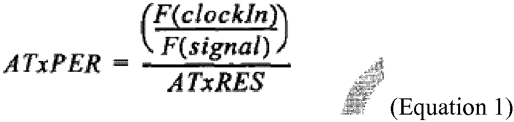
Figure 16 ) divides clock_in by the user-specified ATxRES value stored in the respective register. The resulting clock (clock_in/ATRES) is used to clock a counter. At the end of the input period (that is, the next active edge of signal_in), the value given byEquation 1 is latched into register ATxPER , and an interrupt is signaled (except when inhibited).
- At the same time, the second chain (
Figure 17 ) divides clock_in by register ATxPER, which holds the value measured in the previous cycle. The resulting clock (clock_in/ATPER) clocks the counter which may be read as ATxANG. By the same reasoning used for ATxPER, the angle counter (if theoretically sampled at the end of the period) will be as shown inEquation 2.
- Comparing
Equation 1 andEquation 2 will show that ATxANG should count from zero to a value equal to ATxRES during the ATSIG period. Therefore, the clock to the ATANG counter can be seen to have a frequency of F(signal) ·A TRES, which is the required angle clock. - Note that, if the input period changes, the angle clock period will not change until the next cycle. It follows that, at the end of a cycle, the value in ATxANG may be more or less than ATxRES. Realize also that the ATxANG counter is not required for the generation of at_angle_clock. The counter is a module feature that allows for the capture and compare logic, and for the user to monitor instantaneous input angle.
- When ATSIG represents the rotation of a machine or the AC mains, the input is understood to provide 1 active edge every 360 degrees. Since the angle clock equally divides the signal period, the clock also divides the 360 degree period of rotation, and each clock pulse marks a fixed angle of that rotation, AR (Equation 3).

- ATxANG is cleared to zero at the start of the rotation (that is, at the at_period_clk pulse), and then counts up throughout the cycle, so the value of the counter is linearly related to the instantaneous phase angle as shown in
Equation 4. - A timing example is shown in
Figure 26 , with ATxRES = 5, making an angle clock pulse every 360/5 = 72 degrees.
- The value of ATRES determines the resolution of the period measurement and strongly affects the timing of the angle clock at the end of each revolution. When ATRES is small, ATxPER will count to a high value. ATxPER truncates the actual period value, so the inherent accuracy is +0/-1 counts, multiplied by ATRES (because period is measured in increments of ATRES). Counting to a high ATxPER means the error is a smaller percentage of the total. When ATRES is large (say, 720), the value in ATxPER will be small, and the truncation will be a significant error source. The truncation error accumulates in the angle pulse position, with each arriving more early than its predecessors. If ATRES is large, the last period clock could be early by many clocks. The practical issue here is that reading ATxANG and applying Equation 2-4 can often produce a value that is > 360°.
- A small ATxRES is advantageous for accuracy, but may not meet system requirements. The figure-of-merit of the system is defined as the minimum expected ATxPER value, and
Equation 1 may be rewritten asEquation 5. It is recommended that for good operation, select clock_in and ATxRES to give FOM > 500. - As
Equation 1 shows, a high-frequency clock_in will produce higher counts, and lower percentage error, at the expense of higher system power. If ATxPER overflows, the ATPOV bit will be set in a control register, and the value of ATxPER will not be updated (it follows that ATVALID may remain unset until the 3rd signal cycle).
- When the signal at ATSIG is lost, the period counter will overflow and ATPOV becomes 1. However, there is no period interrupt, and the value in ATxPER is not updated, so the angle clock frequency will not change. Eventually even ATxANG will overflow, and ATVALID will become 0. Note, the missing pulse detector should be used to detect loss of input and create an interrupt. The time-out value will be (a) guaranteed, and (b) much shorter than can be achieved by waiting for ATxANG overflow.
- The angle clock output is not accurate until the input period has been correctly sampled, which requires at least two complete input cycles (see the example in
-
Figure 26 ). Accordingly, the angle clock is gated off while ATVALID = O, the angle counter will not advance, and no angle interrupt will occur. ATVALID is held at O whenever ATEN= O or ATxRES = O, or becomes O because of:
            any reset (including cfg_at_en = 0),
            any write to ATxRES (Register 1-1 ),
            angle counter overflow, or
            freeze (freeze= 1).
- period clock output and interrupts,
- missed-pulse pulse output and interrupts,
- angle clock output and interrupts,
- angle counter counting,
- capture logic and associated interrupt,
- compare logic and associated interrupt.
Because so many pulses are occurring on ATSIG, the value of ATRES must be set fairly low to achieve a suitable FOM. A reasonable value may be less than 5.

- 1. In devices with COG (
Figure 21 ), the start and stop angles of the output pulse can be set using separate compare registers. - 2. A fixed-duration output is often useful when valves must be opened, to deliver a fixed volume of product.
Figure 22 shows a COG system where the start angle is set, and the output duration is determined by a TMR2+HLT with a separate timer clock. - 3.
Figure 23 is similar to #1, but uses the RS flop in a CLC to generate the output pulse in a device that has only a CWG. The CLC is also useful for cases where software must be involved in enabling or disabling the output.
Claims (14)
- An angular timer peripheral comprising two divider chains configured to both measure the period of a rotational input signal (signal_in) of unknown frequency, wherein the rotational input signal (signal_in) comprises a series of index pulses per rotation wherein at least one pulse is missing to indicate a position;wherein the first divider chain comprises:an interval measurement unit (110) configured to determine an interval time of an interval defined by succeeding pulses of the input signal (singal_in) by a counter (910, 915) receiving a system clock (clk_in) and comprising a latch (ATxPER) configured to store said measured interval time value; anda missing pulse detector operable to create a signed difference by comparing the measured interval time value latched from the previous cycle and stored in said latch (ATxPER) with the current interval counter value and to compare the signed difference with a parameter stored in a register (ATxMISS) to determine whether a pulse is missing in the input signal (signal_in), wherein the parameter stored in said register (ATxMISS) is defined by the previously measured period value and a predetermined factor by which the previously measured interval must be exceeded, wherein the missing pulse detector comprises logic for outputting a signal (at_missed_pulse) indicating a missing pulse;and wherein the second divider chain comprises:
an angle generator unit configured to deliver at its output a signal (at angle clock) having a frequency which is a multiple of the frequency of the rotational input signal (signal in), whereby the angle generator unit comprises a counter receiving a clock signal defined by the system clock (elk in) divided by the value held in said latch (ATxPER) from the previous cycle of the input signal. - The angular timer peripheral according to claim 1, wherein the angular timer peripheral is programmable to select whether an input signal (signal_in) comprises a missing pulse in which case the interval measurement unit and missing pulse detector are enabled.
- The angular timer peripheral according to claim 2, wherein a sensor providing the input signal can be selected from being a zero-cross detector, a notched wheel sensor, a double-notched wheel sensor and a flywheel teeth sensor.
- The angular timer peripheral according to one of the preceding claims, wherein the signal indicating the missing pulse (at_missed_pulse) is an interrupt signal.
- The angular timer peripheral according to claim 1, wherein the angular timer peripheral is configured to select a type of input signal which enable or disable a missing pulse detection.
- The angular timer peripheral according to one of the preceding claims, further comprising means to generate a pulse width modulation (PWM) signal from the output pulses.
- The angular timer peripheral according to one of the preceding claims, wherein the index pulse is generated by a rotary machine, and wherein the measured period is a period of rotation.
- A method for measuring a period of an unknown frequency, comprising:receiving a series of index pulses from a rotational input signal (signal_in) , wherein the rotational input signal (signal_in) comprises a series of index pulses per rotation wherein at least one pulse is missing to indicate a position;measuring by an interval measurement unit an interval time of an interval defined by succeding pulses of the input signal (signal_in) by means of a first counter (910, 915) being clocked by a system clock (clk_in) and comparing a latch (AtxPER) storing said measured interval time;creating by a missing pulse detector a signed difference by comparing the measured interval time value latched from the previous cycle and stored in said latch (ATxPER) with the current interval counter value,comparing the signed difference with a parameter stored in a register (ATxMISS) to determine whether a pulse is missing in the input signal, wherein the parameter stored in said register (ATxMISS) is defined by the previously measured period value and a predetermined factor by which the previously measured interval must be exceeded, wherein the missing pulse detector comprises logic for outputting a signal (at_missed_pulse) indicating a missing pulse; anddelivering at an output of an angle generator unit a signal (at angle clock) having a frequency which is a multiple of the frequency of the rotational input signal (signal in). whereby the angle generator unit comprises a counter receiving a clock signal defined by the system clock (elk in) divided by the value held in said latch (ATxPER) from the previous cycle of the input signal.
- The method according to claim 8, comprising the step of selecting whether an input signal (signal_in) comprises a missing pulse in which case the interval measurement unit and missing pulse detector are enabled.
- The method according to claim 9, wherein a sensor providing the input signal can be selected from being a zero-cross detector, a notched wheel sensor, a double-notched wheel sensor and a flywheel teeth sensor.
- The method according to one of the preceding claims 8-10, wherein the signal indicating the missing pulse (at_missed_pulse) is an interrupt signal.
- The method according to claim 8, comprising the step of selecting a type of input signal which enable or disable a missing pulse detection.
- The method according to one of the preceding claims 8-12, further comprising:
generating a pulse width modulation (PWM) signal from the output pulses. - The method according to one of the preceding claims 8-13, wherein the index pulse is generated by a rotary machine, and wherein the measured period is a period of rotation.
Applications Claiming Priority (2)
| Application Number | Priority Date | Filing Date | Title |
|---|---|---|---|
| US201461934218P | 2014-01-31 | 2014-01-31 | |
| PCT/US2015/013513 WO2015116813A1 (en) | 2014-01-31 | 2015-01-29 | Digital period divider |
Publications (2)
| Publication Number | Publication Date |
|---|---|
| EP3100356A1 EP3100356A1 (en) | 2016-12-07 |
| EP3100356B1 true EP3100356B1 (en) | 2025-03-12 |
Family
ID=53754594
Family Applications (1)
| Application Number | Title | Priority Date | Filing Date |
|---|---|---|---|
| EP15703421.6A Active EP3100356B1 (en) | 2014-01-31 | 2015-01-29 | Digital period divider |
Country Status (6)
| Country | Link |
|---|---|
| US (1) | US10048089B2 (en) |
| EP (1) | EP3100356B1 (en) |
| KR (1) | KR20160114070A (en) |
| CN (1) | CN105917584B (en) |
| TW (1) | TWI654843B (en) |
| WO (1) | WO2015116813A1 (en) |
Families Citing this family (9)
| Publication number | Priority date | Publication date | Assignee | Title |
|---|---|---|---|---|
| FR3037392B1 (en) * | 2015-06-12 | 2018-11-09 | Renault S.A.S. | METHOD FOR CALCULATING A WHEEL SPEED AND CORRESPONDING MEASURING DEVICE |
| EP3483565B1 (en) * | 2016-07-07 | 2021-10-20 | FUJIFILM Corporation | Encoder signal processing device, printer, imaging device equipped with printer, and encoder signal processing method |
| KR102491691B1 (en) * | 2018-02-23 | 2023-01-27 | 에스케이하이닉스 주식회사 | Read time-out manager and memory system including the read time-out manager, and method of managing a read time-out |
| GB202015555D0 (en) * | 2020-10-01 | 2020-11-18 | Thermo Fisher Scient Bremen Gmbh | Determining the average frequency of a series of pulses |
| DE102021100751B3 (en) | 2021-01-15 | 2022-07-07 | Knorr-Bremse Systeme für Nutzfahrzeuge GmbH | Processing device and method for processing a sensor signal of a sensor for a vehicle and sensor system with a sensor and a processing device |
| CN115931031B (en) * | 2022-11-10 | 2025-04-01 | 北京青云航空仪表有限公司 | Angle position sensor measuring device |
| CN116609542A (en) * | 2023-05-15 | 2023-08-18 | 绿源动力科技股份有限公司 | Electric vehicle motor speed value generating device |
| CN118393968B (en) * | 2024-06-24 | 2024-09-13 | 杭州胜金微电子有限公司 | A clock detection and control circuit |
| CN120177818A (en) * | 2025-05-20 | 2025-06-20 | 中核核电运行管理有限公司 | A measurement board for converting speed pulse signals of nuclear power plant steam turbines |
Citations (3)
| Publication number | Priority date | Publication date | Assignee | Title |
|---|---|---|---|---|
| JPS58113766A (en) * | 1981-12-26 | 1983-07-06 | Nippon Seiki Co Ltd | Pulse counting device |
| US4408290A (en) * | 1980-01-14 | 1983-10-04 | Nissan Motor Company, Limited | Method and device for determining acceleration and/or deceleration of a moving object |
| EP0789457A2 (en) * | 1996-02-12 | 1997-08-13 | Snap-on Technologies, Inc. | Method and apparatus for detection of missing pulses from a repetitive pulse train |
Family Cites Families (12)
| Publication number | Priority date | Publication date | Assignee | Title |
|---|---|---|---|---|
| DE2653351B2 (en) | 1976-11-24 | 1978-09-07 | Wabco Westinghouse Gmbh, 3000 Hannover | Method for digitally measuring the speed and circuit arrangement for carrying out the method |
| US5625276A (en) * | 1994-09-14 | 1997-04-29 | Coleman Powermate, Inc. | Controller for permanent magnet generator |
| US5699009A (en) | 1996-04-01 | 1997-12-16 | Ford Motor Company | Electronic filtering device |
| KR100446612B1 (en) * | 2001-07-24 | 2004-09-04 | 삼성전자주식회사 | Method and apparatus for selecting information in multi-dimensional space |
| US6621242B2 (en) * | 2001-10-01 | 2003-09-16 | Silicon Touch Technology Inc. | Motor speed control circuit having a synchronous PWM signal |
| US7015832B2 (en) * | 2004-05-25 | 2006-03-21 | Bei Sensors & Systems Company, Inc. | Pulse width modulation based digital incremental encoder |
| JP5298502B2 (en) | 2007-02-05 | 2013-09-25 | セイコーエプソン株式会社 | Method and apparatus for measuring rotational speed of rotating equipment |
| JP5180627B2 (en) * | 2008-03-11 | 2013-04-10 | ルネサスエレクトロニクス株式会社 | Counter circuit |
| JP5381170B2 (en) | 2008-05-07 | 2014-01-08 | セイコーエプソン株式会社 | Velocity measuring method and apparatus |
| JP2010200599A (en) | 2009-01-30 | 2010-09-09 | Rohm Co Ltd | Rotation speed detection circuit, and motor driver having the same |
| US9151840B2 (en) | 2012-03-09 | 2015-10-06 | Semiconductor Components Industries, Llc | Semiconductor device and method of forming same for acoustic sensing of close proximity objects |
| US8908823B2 (en) | 2013-03-12 | 2014-12-09 | Microchip Technology Incorporated | Digital period divider |
-
2015
- 2015-01-29 KR KR1020167020036A patent/KR20160114070A/en not_active Withdrawn
- 2015-01-29 WO PCT/US2015/013513 patent/WO2015116813A1/en not_active Ceased
- 2015-01-29 US US14/608,753 patent/US10048089B2/en active Active
- 2015-01-29 CN CN201580005048.4A patent/CN105917584B/en active Active
- 2015-01-29 EP EP15703421.6A patent/EP3100356B1/en active Active
- 2015-01-30 TW TW104103298A patent/TWI654843B/en active
Patent Citations (3)
| Publication number | Priority date | Publication date | Assignee | Title |
|---|---|---|---|---|
| US4408290A (en) * | 1980-01-14 | 1983-10-04 | Nissan Motor Company, Limited | Method and device for determining acceleration and/or deceleration of a moving object |
| JPS58113766A (en) * | 1981-12-26 | 1983-07-06 | Nippon Seiki Co Ltd | Pulse counting device |
| EP0789457A2 (en) * | 1996-02-12 | 1997-08-13 | Snap-on Technologies, Inc. | Method and apparatus for detection of missing pulses from a repetitive pulse train |
Also Published As
| Publication number | Publication date |
|---|---|
| CN105917584B (en) | 2019-03-01 |
| TW201547198A (en) | 2015-12-16 |
| EP3100356A1 (en) | 2016-12-07 |
| US20150219474A1 (en) | 2015-08-06 |
| TWI654843B (en) | 2019-03-21 |
| CN105917584A (en) | 2016-08-31 |
| KR20160114070A (en) | 2016-10-04 |
| US10048089B2 (en) | 2018-08-14 |
| WO2015116813A1 (en) | 2015-08-06 |
Similar Documents
| Publication | Publication Date | Title |
|---|---|---|
| US10048089B2 (en) | Digital period divider | |
| US8344723B2 (en) | Phase difference resolver of estimated real-time output | |
| CN106645786B (en) | Permanent magnet synchronous motor speed detection method and device | |
| GB1344386A (en) | Phase signal responsive system | |
| JP2019070603A (en) | Abz phase frequency divider | |
| CN108458653A (en) | position detecting device | |
| EP2972411B1 (en) | Digital period divider and method of operating the same | |
| KR890002741A (en) | Apparatus for triggering an event in conjunction with each position of a rotating part and its application | |
| KR100203063B1 (en) | Speed detecting apparatus in encoder type motor | |
| JP4782434B2 (en) | Rotation detection device signal processing device | |
| EP2660565B1 (en) | Digital logic circuit and method for detecting a relative shaft position on geared shafts | |
| KR101135253B1 (en) | Method for sensing motor speed | |
| JPH05188067A (en) | Servo motor speed detecting device | |
| SU983576A1 (en) | Phase inverter phase error measuring device | |
| SU1133668A1 (en) | Angular displacement encoder | |
| JP3045644B2 (en) | Carrier movement controller and pulse frequency converter | |
| JP2961987B2 (en) | Rotational position detecting device for internal combustion engine | |
| SU1251332A1 (en) | Shaft turn angle-to-digital converter | |
| JPH05332788A (en) | Data processing device for rotary encoder | |
| JP2012154856A (en) | Frequency measurement device and frequency phase difference comparison device | |
| JP2021110735A (en) | Low latency variable rotational frequency measurement | |
| JP2002323346A (en) | Encoder | |
| JP2019158667A (en) | Speed and position detector | |
| JPS63265116A (en) | Signal-gradient measuring instrument | |
| JPS62214318A (en) | Position information generating device |
Legal Events
| Date | Code | Title | Description |
|---|---|---|---|
| PUAI | Public reference made under article 153(3) epc to a published international application that has entered the european phase |
Free format text: ORIGINAL CODE: 0009012 |
|
| STAA | Information on the status of an ep patent application or granted ep patent |
Free format text: STATUS: REQUEST FOR EXAMINATION WAS MADE |
|
| 17P | Request for examination filed |
Effective date: 20160805 |
|
| AK | Designated contracting states |
Kind code of ref document: A1 Designated state(s): AL AT BE BG CH CY CZ DE DK EE ES FI FR GB GR HR HU IE IS IT LI LT LU LV MC MK MT NL NO PL PT RO RS SE SI SK SM TR |
|
| AX | Request for extension of the european patent |
Extension state: BA ME |
|
| DAX | Request for extension of the european patent (deleted) | ||
| STAA | Information on the status of an ep patent application or granted ep patent |
Free format text: STATUS: EXAMINATION IS IN PROGRESS |
|
| 17Q | First examination report despatched |
Effective date: 20200114 |
|
| GRAP | Despatch of communication of intention to grant a patent |
Free format text: ORIGINAL CODE: EPIDOSNIGR1 |
|
| STAA | Information on the status of an ep patent application or granted ep patent |
Free format text: STATUS: GRANT OF PATENT IS INTENDED |
|
| INTG | Intention to grant announced |
Effective date: 20241002 |
|
| GRAS | Grant fee paid |
Free format text: ORIGINAL CODE: EPIDOSNIGR3 |
|
| GRAA | (expected) grant |
Free format text: ORIGINAL CODE: 0009210 |
|
| STAA | Information on the status of an ep patent application or granted ep patent |
Free format text: STATUS: THE PATENT HAS BEEN GRANTED |
|
| AK | Designated contracting states |
Kind code of ref document: B1 Designated state(s): AL AT BE BG CH CY CZ DE DK EE ES FI FR GB GR HR HU IE IS IT LI LT LU LV MC MK MT NL NO PL PT RO RS SE SI SK SM TR |
|
| REG | Reference to a national code |
Ref country code: GB Ref legal event code: FG4D |
|
| REG | Reference to a national code |
Ref country code: CH Ref legal event code: EP |
|
| REG | Reference to a national code |
Ref country code: DE Ref legal event code: R096 Ref document number: 602015091186 Country of ref document: DE |
|
| REG | Reference to a national code |
Ref country code: IE Ref legal event code: FG4D |
|
| PG25 | Lapsed in a contracting state [announced via postgrant information from national office to epo] |
Ref country code: RS Free format text: LAPSE BECAUSE OF FAILURE TO SUBMIT A TRANSLATION OF THE DESCRIPTION OR TO PAY THE FEE WITHIN THE PRESCRIBED TIME-LIMIT Effective date: 20250612 |
|
| PG25 | Lapsed in a contracting state [announced via postgrant information from national office to epo] |
Ref country code: FI Free format text: LAPSE BECAUSE OF FAILURE TO SUBMIT A TRANSLATION OF THE DESCRIPTION OR TO PAY THE FEE WITHIN THE PRESCRIBED TIME-LIMIT Effective date: 20250312 |
|
| PG25 | Lapsed in a contracting state [announced via postgrant information from national office to epo] |
Ref country code: ES Free format text: LAPSE BECAUSE OF FAILURE TO SUBMIT A TRANSLATION OF THE DESCRIPTION OR TO PAY THE FEE WITHIN THE PRESCRIBED TIME-LIMIT Effective date: 20250312 |
|
| REG | Reference to a national code |
Ref country code: LT Ref legal event code: MG9D |
|
| PG25 | Lapsed in a contracting state [announced via postgrant information from national office to epo] |
Ref country code: NO Free format text: LAPSE BECAUSE OF FAILURE TO SUBMIT A TRANSLATION OF THE DESCRIPTION OR TO PAY THE FEE WITHIN THE PRESCRIBED TIME-LIMIT Effective date: 20250612 |
|
| PG25 | Lapsed in a contracting state [announced via postgrant information from national office to epo] |
Ref country code: HR Free format text: LAPSE BECAUSE OF FAILURE TO SUBMIT A TRANSLATION OF THE DESCRIPTION OR TO PAY THE FEE WITHIN THE PRESCRIBED TIME-LIMIT Effective date: 20250312 |
|
| REG | Reference to a national code |
Ref country code: NL Ref legal event code: MP Effective date: 20250312 |
|
| PG25 | Lapsed in a contracting state [announced via postgrant information from national office to epo] |
Ref country code: LV Free format text: LAPSE BECAUSE OF FAILURE TO SUBMIT A TRANSLATION OF THE DESCRIPTION OR TO PAY THE FEE WITHIN THE PRESCRIBED TIME-LIMIT Effective date: 20250312 |
|
| PG25 | Lapsed in a contracting state [announced via postgrant information from national office to epo] |
Ref country code: GR Free format text: LAPSE BECAUSE OF FAILURE TO SUBMIT A TRANSLATION OF THE DESCRIPTION OR TO PAY THE FEE WITHIN THE PRESCRIBED TIME-LIMIT Effective date: 20250613 Ref country code: BG Free format text: LAPSE BECAUSE OF FAILURE TO SUBMIT A TRANSLATION OF THE DESCRIPTION OR TO PAY THE FEE WITHIN THE PRESCRIBED TIME-LIMIT Effective date: 20250312 |
|
| REG | Reference to a national code |
Ref country code: AT Ref legal event code: MK05 Ref document number: 1775888 Country of ref document: AT Kind code of ref document: T Effective date: 20250312 |
|
| PG25 | Lapsed in a contracting state [announced via postgrant information from national office to epo] |
Ref country code: NL Free format text: LAPSE BECAUSE OF FAILURE TO SUBMIT A TRANSLATION OF THE DESCRIPTION OR TO PAY THE FEE WITHIN THE PRESCRIBED TIME-LIMIT Effective date: 20250312 |
|
| PG25 | Lapsed in a contracting state [announced via postgrant information from national office to epo] |
Ref country code: SE Free format text: LAPSE BECAUSE OF FAILURE TO SUBMIT A TRANSLATION OF THE DESCRIPTION OR TO PAY THE FEE WITHIN THE PRESCRIBED TIME-LIMIT Effective date: 20250312 |
|
| PG25 | Lapsed in a contracting state [announced via postgrant information from national office to epo] |
Ref country code: SM Free format text: LAPSE BECAUSE OF FAILURE TO SUBMIT A TRANSLATION OF THE DESCRIPTION OR TO PAY THE FEE WITHIN THE PRESCRIBED TIME-LIMIT Effective date: 20250312 |
|
| PG25 | Lapsed in a contracting state [announced via postgrant information from national office to epo] |
Ref country code: PT Free format text: LAPSE BECAUSE OF FAILURE TO SUBMIT A TRANSLATION OF THE DESCRIPTION OR TO PAY THE FEE WITHIN THE PRESCRIBED TIME-LIMIT Effective date: 20250714 |
|
| PG25 | Lapsed in a contracting state [announced via postgrant information from national office to epo] |
Ref country code: PL Free format text: LAPSE BECAUSE OF FAILURE TO SUBMIT A TRANSLATION OF THE DESCRIPTION OR TO PAY THE FEE WITHIN THE PRESCRIBED TIME-LIMIT Effective date: 20250312 Ref country code: IT Free format text: LAPSE BECAUSE OF FAILURE TO SUBMIT A TRANSLATION OF THE DESCRIPTION OR TO PAY THE FEE WITHIN THE PRESCRIBED TIME-LIMIT Effective date: 20250312 |
|
| PG25 | Lapsed in a contracting state [announced via postgrant information from national office to epo] |
Ref country code: AT Free format text: LAPSE BECAUSE OF FAILURE TO SUBMIT A TRANSLATION OF THE DESCRIPTION OR TO PAY THE FEE WITHIN THE PRESCRIBED TIME-LIMIT Effective date: 20250312 |
|
| PG25 | Lapsed in a contracting state [announced via postgrant information from national office to epo] |
Ref country code: EE Free format text: LAPSE BECAUSE OF FAILURE TO SUBMIT A TRANSLATION OF THE DESCRIPTION OR TO PAY THE FEE WITHIN THE PRESCRIBED TIME-LIMIT Effective date: 20250312 Ref country code: CZ Free format text: LAPSE BECAUSE OF FAILURE TO SUBMIT A TRANSLATION OF THE DESCRIPTION OR TO PAY THE FEE WITHIN THE PRESCRIBED TIME-LIMIT Effective date: 20250312 |
|
| PG25 | Lapsed in a contracting state [announced via postgrant information from national office to epo] |
Ref country code: RO Free format text: LAPSE BECAUSE OF FAILURE TO SUBMIT A TRANSLATION OF THE DESCRIPTION OR TO PAY THE FEE WITHIN THE PRESCRIBED TIME-LIMIT Effective date: 20250312 |
|
| PG25 | Lapsed in a contracting state [announced via postgrant information from national office to epo] |
Ref country code: SK Free format text: LAPSE BECAUSE OF FAILURE TO SUBMIT A TRANSLATION OF THE DESCRIPTION OR TO PAY THE FEE WITHIN THE PRESCRIBED TIME-LIMIT Effective date: 20250312 |
|
| PG25 | Lapsed in a contracting state [announced via postgrant information from national office to epo] |
Ref country code: IS Free format text: LAPSE BECAUSE OF FAILURE TO SUBMIT A TRANSLATION OF THE DESCRIPTION OR TO PAY THE FEE WITHIN THE PRESCRIBED TIME-LIMIT Effective date: 20250712 |
|
| REG | Reference to a national code |
Ref country code: DE Ref legal event code: R097 Ref document number: 602015091186 Country of ref document: DE |
|
| PG25 | Lapsed in a contracting state [announced via postgrant information from national office to epo] |
Ref country code: DK Free format text: LAPSE BECAUSE OF FAILURE TO SUBMIT A TRANSLATION OF THE DESCRIPTION OR TO PAY THE FEE WITHIN THE PRESCRIBED TIME-LIMIT Effective date: 20250312 |
|
| PLBE | No opposition filed within time limit |
Free format text: ORIGINAL CODE: 0009261 |
|
| STAA | Information on the status of an ep patent application or granted ep patent |
Free format text: STATUS: NO OPPOSITION FILED WITHIN TIME LIMIT |
|
| REG | Reference to a national code |
Ref country code: CH Ref legal event code: L10 Free format text: ST27 STATUS EVENT CODE: U-0-0-L10-L00 (AS PROVIDED BY THE NATIONAL OFFICE) Effective date: 20260121 |
|
| 26N | No opposition filed |
Effective date: 20251215 |
|
| PGFP | Annual fee paid to national office [announced via postgrant information from national office to epo] |
Ref country code: DE Payment date: 20251217 Year of fee payment: 12 |