EP3099998B1 - Zieltrainingssystem - Google Patents
Zieltrainingssystem Download PDFInfo
- Publication number
- EP3099998B1 EP3099998B1 EP15820232.5A EP15820232A EP3099998B1 EP 3099998 B1 EP3099998 B1 EP 3099998B1 EP 15820232 A EP15820232 A EP 15820232A EP 3099998 B1 EP3099998 B1 EP 3099998B1
- Authority
- EP
- European Patent Office
- Prior art keywords
- target
- training system
- processor
- target objects
- objects
- Prior art date
- Legal status (The legal status is an assumption and is not a legal conclusion. Google has not performed a legal analysis and makes no representation as to the accuracy of the status listed.)
- Active
Links
Images


Classifications
-
- F—MECHANICAL ENGINEERING; LIGHTING; HEATING; WEAPONS; BLASTING
- F41—WEAPONS
- F41J—TARGETS; TARGET RANGES; BULLET CATCHERS
- F41J5/00—Target indicating systems; Target-hit or score detecting systems
- F41J5/06—Acoustic hit-indicating systems, i.e. detecting of shock waves
-
- F—MECHANICAL ENGINEERING; LIGHTING; HEATING; WEAPONS; BLASTING
- F41—WEAPONS
- F41J—TARGETS; TARGET RANGES; BULLET CATCHERS
- F41J1/00—Targets; Target stands; Target holders
- F41J1/10—Target stands; Target holders
-
- F—MECHANICAL ENGINEERING; LIGHTING; HEATING; WEAPONS; BLASTING
- F41—WEAPONS
- F41J—TARGETS; TARGET RANGES; BULLET CATCHERS
- F41J9/00—Moving targets, i.e. moving when fired at
- F41J9/04—Seagoing targets
Definitions
- This invention relates to a target training system, and in particular to an automated target training system.
- Target training systems are commonly used to test and improve the accuracy of a marksman during target practice. It is useful for automated target training systems to be able to provide real-time feedback to the marksman or their coach. On land ranges this saves time for personnel who would otherwise physically have to check the target for impacts of projectiles (for example rounds or bullets); and reduces the number of personnel because one person can check feedback for several targets. On maritime ranges (i.e. a target floating on the surface of water) it is even more difficult, often prohibitively so, to physically check the target for impacts.
- US Patent 5,095,433 discloses an automated target training system which uses a plurality of vibration -sensors attached to a target.
- the outputs of the vibration sensors are voltage signals which are transmitted to a processor.
- a part of the processor acts as a comparator, the output of the comparator is biased at a low level until a voltage signal of sufficient strength is received from the sensors. If the processor determines that the target has been struck, an audible tone is outputted to the marksman, to inform them of an accurate shot.
- systems for detecting the impact point on a target are known from Patent Application Publications US 2012/0091660 A1 and US 2009/0102129 A1 .
- the target having a plurality of target objects positioned adjacent to each other with a gap provided between them allows the target to be divided into discreet target objects. Therefore a projectile fired by a marksman can only hit one or some, but not all the target objects. This means that when a projectile is fired vibrations from background noise and vibrations from the noise of a shock wave of a projectile passing close by will be common to all sensors. However, vibrations picked up from the impact of a projectile will not be picked up by all target objects. Subsequently, the output signals from vibration sensors attached to each target object are compared by a processor. The processor determines when a relative threshold value higher than the lowest value of all the output signals compared by the processor is exceeded and identifies this as a hit. The result is that, even when the target is in the presence of background noise, the target training system can distinguish when a hit has been recorded.
- a suitable relative threshold value may be set at two to three times higher than the value of the lowest value of output signal. However, other relative threshold values may also be used.
- a relative threshold value can be set both for vibrations from a shockwave of a projectile passing close to all the target objects, and also for vibrations from an impact of a projectile. Therefore two relative threshold values higher than the lowest value output signal may be used.
- the first relative threshold value higher would indicate when a near miss had occurred because all target objects would be transmitting output signals to the processor higher than background noise.
- the second relative threshold value being set higher than the first relative threshold value would indicate an impact of one or more target objects.
- a target is understood to mean a single zone for a marksman to shoot at.
- the target could be a plate with a printed picture of a person attached, or a picture of coloured concentric rings. Therefore a target object is understood as a discreet part of the target zone.
- the output signals of the sensors attached to the target objects can be transmitted to a processor such as a computer by a cable or other hardwired connector attached to the sensor (such as fibre optic or electrical). If a fibre optic cable is used, it will be appreciated that electrical to optic converters may be required at either end of the cable to ensure that the measurement signal is in a format that can be processed by the processor.
- the output signals may be transmitted to the processor by wireless technology for example a Radio Frequency (RF) signal using a RF transmitter connected to the sensor.
- the RF signal can then be received by a RF receiver, the signal being converted for use by the processor.
- Other forms of wireless technology known in the art may also be used.
- the advantage of wireless technology is that the output signals may be transmitted in situations where the use of a cable would be less practical such as when the target is some distance from the marksman or where the target is floating on water.
- the processor can output the results of each projectile fired onto a video display so that the marksman or coach can monitor performance.
- the processor is configured to apply an appropriate threshold value or values so as to determine whether or not at least one of the target objects has been impacted by a projectile.
- the output of the processor may be a binary string representing, for example, a series of 'hit'/'no hit' values for each target object.
- the output of the processor may be transmitted from the processor by a wireless or wired connection (as appropriate) and may be communicated to the user in any suitable way, for example by means of a graphical user interface, an audible signal, an optical signal (for example flashing lights) or even as a tactile response (for example a vibration mode).
- Communication to the user by an optical signal attached to the target system is particularly preferred because of simplicity, low cost, no reliance on cables or wired connections and potential operation over water and/or long distance.
- a narrow band optical signal can be used, in conjunction with a camera and suitable filter at the firing point.
- a target can be designed with the plurality of target objects, preferably more than two target objects, positioned symmetrically or approximately symmetrically around a vertical axis.
- This arrangement is particularly suited to maritime ranges because it enables the orientation of the target relative to the marksman to vary without affecting the utility of the target, for example if the target turns due to movement of ocean currents. It also prevents the target from acting as a sail and turning in the wind, as might happen where the target objects are all aligned along a linear axis.
- a plurality of target objects may be attached to a base made from or comprising rubber, foam, wood or any other suitable material for absorbing vibration.
- the base may be configured to support the weight of the target objects during training, which may be especially advantageous in windy weather conditions.
- the target objects may be attached to a base made from or comprising a buoyant material such as rubber, foam or wood, so that the target is suitable for use on water or in maritime environments.
- the base may take the form of a support framework, for example a square frame made from metal or wood, or a hull structure.
- the frame may have vibration damping fixtures, for example rubber fixtures, for attaching the target objects.
- the vibration damping fixtures help to prevent vibrations caused by movement of the frame from being picked up by the vibration sensors attached to the target objects, and may also reduce the transmission of vibration between target objects via the frame.
- Vibration damping fixtures may take any suitable form (for example resilient components such a springs) and/or may comprise any suitable material, for example rubbers or foams. Wheels may be attached to the base to allow it to be towed, for example behind a vehicle.
- the base may alternatively be attached to a moving platform such as those used in a gallery target training system or a remote controlled boat, to provide a shooter with a remote controlled mobile target.
- FIG. 1a The plan view of Fig. 1a shows a view from above an array of target objects 2, 3 with vibration sensors attached.
- FIG. 1b The front view of Fig. 1b indicates schematically what a marksman carrying out target training would see.
- Two adjacent target objects 2, 3 made from rectangular wooden boards 5mm thick and sized 0.6 m x 1.6 m, positioned into the ground adjacent to each other. This can be done by digging two trenches in the earth deep enough to support the target objects 2, 3. Metal plastic or other suitable rigid material could also be used for the target objects. The size of target objects could be varied dependent on the distance between the marksman and the target objects.
- a gap 5 between the target objects 2, 3, isolates them from mutual transmission of vibration, if one of the target objects 2, 3 is struck by a projectile. The gap between the target objects should be sufficient that they do not come into contact when excited by a projectile striking a target object.
- the target objects 2, 3 each have vibration sensors 6, 7 attached by screws, however any secure attachment method such as adhesive could be used.
- the vibration sensors 6, 7 are MEMS accelerometers, which are each connected to a processor 30 via cables 32, 33. Other type of commercially available vibration sensors could be used. Vibrations from background noise, noise from the shockwave of a projectile passing close to target objects 2, 3 or from a projectile impacting one of the target object 2, 3 will be measured by the vibration sensors 6, 7.
- the output signals of the target object 2, 3 will then be transmitted via cables 32, 33 to the processor 30, so that the signals can be analysed.
- the processor 30 analyses the signals, if at least one of the output signals has an amplitude higher than the lowest output signal, by a set relative threshold value, the processor determines that at least one of the target objects as hit by a projectile.
- FIG. 2a The plan view of Fig. 2a shows a view from above and array of target objects 12, 13, 14 with vibration sensors 16, 17, 18 attached.
- FIG. 2b The front view of Fig. 2b indicates schematically what a marksman carrying out target training would see.
- Three target objects 12, 13, 14 made from thin rectangular metal sheets 2mm thick, sized 0.8m x 2.0m, are positioned substantially symmetrical about a vertical axis 150.
- the target objects 12, 13, 14 are arranged in a triangular geometry, however a higher order of geometry, for example a hexagon could be used.
- the target objects 12, 13, 14 are affixed to a large foam base 19 by sliding the bottom part (not shown) of the target objects 12, 13, 14 into three preformed slots.
- a gap 15 between the target objects 12, 13, 14 isolates them from mutual transmission of vibration, if one of the target objects 12, 13, 14 is struck by a projectile.
- the gap between the target objects should be sufficient that they do not come into contact when either excited by a projectile striking a target object or by movement of the large foam base 19.
- the target objects 12, 13, 14 each have vibration sensors 16, 17, 18 attached by an adhesive.
- the vibration sensors 16, 17, 18 are MEMS accelerometers, which in turn are each connected to a RF transmitter 133 via a short cable (not shown). Vibrations from background noise, noise from the shockwave of a projectile passing close to target objects 12, 13, 14 or from a projectile impacting the one of the target objects 12, 13, 14 will be measured by the vibration sensors 16, 17, 18.
- the output signals will then be transmitted to RF receiver 139, and inputted to processor 130, so that the signals can be analysed.
- the processor 130 can be a computer or another electrical device capable of analysing the signals.
- the processor 130 analyses the signals, if at least one of the output signals has an amplitude higher than the lowest output signal, by a set relative threshold value, the processor determines that at least one of the target objects was hit by a projectile. It is also possible for all the vibration data (output signals) to be transmitted to the processor 130 in real-time and the real-time detection algorithm run on the processor 130.
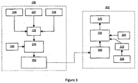
- Figure 3 is a schematic layout of equipment used to measure and record output signals from vibration sensors.
- the equipment could be used in conjunction with different numbers and geometrical arrangements of target objects including the two embodiments already described.
- This embodiment is described with reference to a target using three target objects affixed to a base.
- Equipment used to measure and record output signals, located on target base 200 is comprised of three vibration sensors 206, 207, 208, which measure the amount of vibration there is from the target objects (not shown) to which they are attached.
- Analogue vibration output signals from sensors 206, 207, 208 are fed into a Digital to Analogue Converter or DAC 220. However the DAC 220, is not required if sensors with a digital output signals are used.
- the digital signals are then inputted into a processor 230 so that the signals can be recorded.
- the digital signals are then transmitted via a RF transmitter 350 to the firer platform 300.
- the dashed arrow represents the data communication between the two locations.
- the digital signals are then received at marksman platform 300 by the RF receiver 360.
- a second processor 330 is used to analyse the signals and is configured to determine that at least one of the target objects has been hit by a projectile when the signal taken by the vibration sensor (for example 206) of that target object is a relative threshold value higher than the lowest output signal taken by all the vibration sensors 206, 207, 208.
- the results are outputted onto a visual display 370 so that they can be seen by the marksman and/or coach. Alternatively the results can be outputted to a speaker, different tones indicating whether a hit or a miss has been achieved.
- GPS units 240 and 340 could be used. GPS unit 240 inputs location data of the target base 200 into the processor 230 and GPS unit 340 inputs location data of the marksman platform 300 into processor 330. The location data from processor 230 is transmitted together with the output signals to the marksman platform 300. All the location data is then finally computed by processor 330 and the location information displayed onto the visual display 370.
- the integration of the measurement equipment, processors, GPS units with a display enable hit and miss; and range to target information to be to outputted to the marksman and/or coach, even if the target is mobile. If a static land range was used then GPS information would not be required because the position of the firer in relation to the target objects would be fixed.
- An additional measurement sensor 306 located at the target platform 300 is used to record when a projectile is fired.
- a vibration sensor, microphone or other measurement sensor could be used.
- the output signal is then converted into digital data by the DAC 320, before inputting into the processor 330.
- the additional data can be computed and displayed for the purpose of indicating accuracy as a percentage as each projectile is fired rather than an absolute number.
- a target training system similar to the embodiment of Figures 2a and 2b was constructed and tested.
- the test system had slightly smaller target objects (each 0.6 m by 1.6 m in size) and reinforcing struts were added to the target objects to reduce flexing under environmental test conditions.
- the vibration sensors were tri-axial 200 g limit ADXL375 accelerometers manufactured by Analog Devices, chosen for their low cost and ability to measure high accelerations. Each sensor was encased in epoxy and embedded in a wooden plate which was in turn bolted to the target plates. This enabled the sensors to be swapped in the event of damage. All vibration sensors were mounted on the inner side of the target object, so as to provide additional protection from the weather and any fragmentation.
- a micro-computer was used for data acquisition and processing.
- Each accelerometer was connected to the micro-computer using a Serial Peripheral Interface (SPI) bus running at 2 MHz, with data measured from each channel with a sample rate of 3.2 kHz.
- Power was supplied by a USB power pack, enabling operation for around 12 hours.
- SPI Serial Peripheral Interface
- the target training system was fixed to a 6 m static towed target boat and calibration of the sensors was undertaken prior to subjecting the target to weapons fire. Accelerometer responses were recorded as a function of time from each sensor, for each of the three axes of that sensor (x, y and z).
- Figure 4 shows the measured vibrational response during part of the weapons fire. Three impact events can be seen, each impact producing a large vibrational response in two target plates. The peak acceleration is well in excess of the noise floor and, moreover, the reverberation of the structure is demonstrated to be sufficiently damped such that the measured accelerations are almost back at the level of the noise floor within approximately 1/10 second. This decay rate gave a good match with the rate of fire of the weapons used in the trial, and shows that detection of individual events is feasible.
- a 'hit' detection algorithm programmed on the micro-computer detected 37 rounds striking the target training system. By counting holes in the target plates after the test, it was estimated that 40 rounds hit the target plates. The difference between the actual and detected hit rate may be due to simultaneous impact from rounds that fragmented on striking the target boat.
Landscapes
- Engineering & Computer Science (AREA)
- General Engineering & Computer Science (AREA)
- Physics & Mathematics (AREA)
- Acoustics & Sound (AREA)
- Aiming, Guidance, Guns With A Light Source, Armor, Camouflage, And Targets (AREA)
Claims (8)
- Zieltrainingssystem, umfassend:ein Ziel, das mehrere Zielobjekte (2, 3, 12, 13, 14) aufweist,wobei die Zielobjekte einander benachbart positioniert sind, wobei ein Abstand (5, 15) zwischen ihnen vorgesehen ist, wobei jedes Zielobjekt einen Vibrationssensor (6, 7, 16, 17, 18, 206, 207, 208), der ein Ausgabesignal erzeugt, aufweist, der daran angebracht ist, undeinen Prozessor (30, 130, 330),wobei der Prozessor ausgelegt ist, festzustellen, dass mindestens ein erstes der Zielobjekte von einem Projektil getroffen wurde, wenn das Ausgabesignal, das mit dem mindestens ersten der Zielobjekte in Verbindung steht, ein relativer Schwellenwert ist, der höher als der niedrigste Wert aller Ausgabesignale ist.
- Zieltrainingssystem nach Anspruch 1, wobei die Ausgabesignale von den Vibrationssensoren durch drahtgebundene Mittel (32, 33) an den Prozessor übertragen werden.
- Zieltrainingssystem nach Anspruch 1, wobei die Ausgabesignale von den Vibrationssensoren durch drahtlose Mittel an den Prozessor übertragen werden, wobei die Mittel vorzugsweise eine HF-Übertragungseinrichtung (133, 350) und - Empfangseinrichtung (139, 360) umfassen.
- Zieltrainingssystem nach einem der Ansprüche 1 bis 3, ferner umfassend eine grafische Benutzeroberfläche oder Audio-/visuelle Anzeige (370), um einem Benutzer Zielaufprallinformationen darzustellen.
- Zieltrainingssystem nach einem der vorangehenden Ansprüche, wobei die Zielobjekte (12, 13, 14) im Wesentlichen symmetrisch um eine vertikale Achse (150) positioniert sind.
- Zieltrainingssystem nach einem der vorangehenden Ansprüche, wobei das System ferner eine Basis (19) umfasst, an der die Zielobjekte (12, 13, 14) befestigt sind.
- Zieltrainingssystem nach Anspruch 6, wobei die Basis ferner Räder umfasst.
- Zieltrainingssystem nach Anspruch 6, wobei die Basis zum Schwimmen auf Wasser ausgelegt ist.
Applications Claiming Priority (2)
| Application Number | Priority Date | Filing Date | Title |
|---|---|---|---|
| GBGB1401631.5A GB201401631D0 (en) | 2014-01-31 | 2014-01-31 | Target training system |
| PCT/GB2015/000032 WO2016016596A2 (en) | 2014-01-31 | 2015-01-29 | Target training system |
Publications (2)
| Publication Number | Publication Date |
|---|---|
| EP3099998A2 EP3099998A2 (de) | 2016-12-07 |
| EP3099998B1 true EP3099998B1 (de) | 2018-10-10 |
Family
ID=50344140
Family Applications (1)
| Application Number | Title | Priority Date | Filing Date |
|---|---|---|---|
| EP15820232.5A Active EP3099998B1 (de) | 2014-01-31 | 2015-01-29 | Zieltrainingssystem |
Country Status (3)
| Country | Link |
|---|---|
| EP (1) | EP3099998B1 (de) |
| GB (1) | GB201401631D0 (de) |
| WO (1) | WO2016016596A2 (de) |
Family Cites Families (3)
| Publication number | Priority date | Publication date | Assignee | Title |
|---|---|---|---|---|
| EP2040025A1 (de) * | 2007-09-21 | 2009-03-25 | Saab Ab | Schießzielsystem zur automatischen Bestimmung der Aufprallstelle |
| US8561993B2 (en) * | 2010-10-18 | 2013-10-22 | Lockheed Martin Corporation | Target impact-point sensing system |
| US8523185B1 (en) * | 2011-02-03 | 2013-09-03 | Don Herbert Gilbreath | Target shooting system and method of use |
-
2014
- 2014-01-31 GB GBGB1401631.5A patent/GB201401631D0/en not_active Ceased
-
2015
- 2015-01-29 WO PCT/GB2015/000032 patent/WO2016016596A2/en not_active Ceased
- 2015-01-29 EP EP15820232.5A patent/EP3099998B1/de active Active
Non-Patent Citations (1)
| Title |
|---|
| None * |
Also Published As
| Publication number | Publication date |
|---|---|
| WO2016016596A3 (en) | 2016-05-06 |
| GB201401631D0 (en) | 2014-03-19 |
| EP3099998A2 (de) | 2016-12-07 |
| WO2016016596A2 (en) | 2016-02-04 |
Similar Documents
| Publication | Publication Date | Title |
|---|---|---|
| US5973998A (en) | Automatic real-time gunshot locator and display system | |
| CA2128333C (en) | Methods and apparatus for determining the trajectory of a supersonic projectile | |
| US20090102129A1 (en) | Shooting target system for automatic determination of the point of impact | |
| CA1236558A (en) | Method and system for depth sounding | |
| CN103673791B (zh) | 一种用于靶标高速撞击损伤的检测评估系统 | |
| WO2011056830A1 (en) | Passive acoustic underwater intruder detection system | |
| US20150247709A1 (en) | Interactive target and system for long range shooting | |
| EP0511293A1 (de) | Vorrichtung zur akustischen auswertung einer geschossflugbahn. | |
| JP7133160B2 (ja) | コンクリート浮き検知装置及び検知方法 | |
| Clements | Shipboard shock and Navy devices for its simulation | |
| EP3099998B1 (de) | Zieltrainingssystem | |
| CN201527225U (zh) | 多位超声速声电定位装置 | |
| CN103869287A (zh) | 枪声定位定向方法 | |
| Simioni et al. | Field measurements of snowpack response to explosive loading | |
| CN212870924U (zh) | 一种枪械射击自动报靶靶标 | |
| KR102180570B1 (ko) | 수중 자기 탐지 장치 및 방법 | |
| US7685862B1 (en) | Target system giving accuracy and energy | |
| US6496447B1 (en) | Target simulation system | |
| RU2519614C1 (ru) | Способ определения фугасного действия объекта испытаний | |
| Compton | An experimental and theoretical investigation of shot cloud ballistics | |
| KR101378106B1 (ko) | 표적 감적 장치 | |
| KR101232049B1 (ko) | 포탄의 낙하위치결정시스템 및 이를 이용한 포탄의 낙하위치 결정방법 | |
| CN107607003B (zh) | 一种靶弹遭拦截撞击后的时间测量装置和方法 | |
| Naz et al. | Acoustic detection and localization of weapons fire by unattended ground sensors and aerostat-borne sensors | |
| Kuklinski | High speed underwater projectile tracking system and method |
Legal Events
| Date | Code | Title | Description |
|---|---|---|---|
| PUAI | Public reference made under article 153(3) epc to a published international application that has entered the european phase |
Free format text: ORIGINAL CODE: 0009012 |
|
| STAA | Information on the status of an ep patent application or granted ep patent |
Free format text: STATUS: REQUEST FOR EXAMINATION WAS MADE |
|
| 17P | Request for examination filed |
Effective date: 20160811 |
|
| AK | Designated contracting states |
Kind code of ref document: A2 Designated state(s): AL AT BE BG CH CY CZ DE DK EE ES FI FR GB GR HR HU IE IS IT LI LT LU LV MC MK MT NL NO PL PT RO RS SE SI SK SM TR |
|
| AX | Request for extension of the european patent |
Extension state: BA ME |
|
| DAX | Request for extension of the european patent (deleted) | ||
| GRAP | Despatch of communication of intention to grant a patent |
Free format text: ORIGINAL CODE: EPIDOSNIGR1 |
|
| STAA | Information on the status of an ep patent application or granted ep patent |
Free format text: STATUS: GRANT OF PATENT IS INTENDED |
|
| RIC1 | Information provided on ipc code assigned before grant |
Ipc: F41J 1/10 20060101ALI20180413BHEP Ipc: F41J 9/04 20060101ALI20180413BHEP Ipc: F41J 5/06 20060101AFI20180413BHEP |
|
| INTG | Intention to grant announced |
Effective date: 20180504 |
|
| GRAS | Grant fee paid |
Free format text: ORIGINAL CODE: EPIDOSNIGR3 |
|
| GRAA | (expected) grant |
Free format text: ORIGINAL CODE: 0009210 |
|
| STAA | Information on the status of an ep patent application or granted ep patent |
Free format text: STATUS: THE PATENT HAS BEEN GRANTED |
|
| AK | Designated contracting states |
Kind code of ref document: B1 Designated state(s): AL AT BE BG CH CY CZ DE DK EE ES FI FR GB GR HR HU IE IS IT LI LT LU LV MC MK MT NL NO PL PT RO RS SE SI SK SM TR |
|
| REG | Reference to a national code |
Ref country code: GB Ref legal event code: FG4D |
|
| REG | Reference to a national code |
Ref country code: CH Ref legal event code: EP Ref country code: AT Ref legal event code: REF Ref document number: 1051748 Country of ref document: AT Kind code of ref document: T Effective date: 20181015 |
|
| REG | Reference to a national code |
Ref country code: IE Ref legal event code: FG4D |
|
| REG | Reference to a national code |
Ref country code: DE Ref legal event code: R096 Ref document number: 602015018056 Country of ref document: DE |
|
| REG | Reference to a national code |
Ref country code: NL Ref legal event code: MP Effective date: 20181010 |
|
| REG | Reference to a national code |
Ref country code: LT Ref legal event code: MG4D |
|
| REG | Reference to a national code |
Ref country code: AT Ref legal event code: MK05 Ref document number: 1051748 Country of ref document: AT Kind code of ref document: T Effective date: 20181010 |
|
| PG25 | Lapsed in a contracting state [announced via postgrant information from national office to epo] |
Ref country code: NL Free format text: LAPSE BECAUSE OF FAILURE TO SUBMIT A TRANSLATION OF THE DESCRIPTION OR TO PAY THE FEE WITHIN THE PRESCRIBED TIME-LIMIT Effective date: 20181010 |
|
| PG25 | Lapsed in a contracting state [announced via postgrant information from national office to epo] |
Ref country code: FI Free format text: LAPSE BECAUSE OF FAILURE TO SUBMIT A TRANSLATION OF THE DESCRIPTION OR TO PAY THE FEE WITHIN THE PRESCRIBED TIME-LIMIT Effective date: 20181010 Ref country code: BG Free format text: LAPSE BECAUSE OF FAILURE TO SUBMIT A TRANSLATION OF THE DESCRIPTION OR TO PAY THE FEE WITHIN THE PRESCRIBED TIME-LIMIT Effective date: 20190110 Ref country code: HR Free format text: LAPSE BECAUSE OF FAILURE TO SUBMIT A TRANSLATION OF THE DESCRIPTION OR TO PAY THE FEE WITHIN THE PRESCRIBED TIME-LIMIT Effective date: 20181010 Ref country code: LV Free format text: LAPSE BECAUSE OF FAILURE TO SUBMIT A TRANSLATION OF THE DESCRIPTION OR TO PAY THE FEE WITHIN THE PRESCRIBED TIME-LIMIT Effective date: 20181010 Ref country code: ES Free format text: LAPSE BECAUSE OF FAILURE TO SUBMIT A TRANSLATION OF THE DESCRIPTION OR TO PAY THE FEE WITHIN THE PRESCRIBED TIME-LIMIT Effective date: 20181010 Ref country code: AT Free format text: LAPSE BECAUSE OF FAILURE TO SUBMIT A TRANSLATION OF THE DESCRIPTION OR TO PAY THE FEE WITHIN THE PRESCRIBED TIME-LIMIT Effective date: 20181010 Ref country code: PL Free format text: LAPSE BECAUSE OF FAILURE TO SUBMIT A TRANSLATION OF THE DESCRIPTION OR TO PAY THE FEE WITHIN THE PRESCRIBED TIME-LIMIT Effective date: 20181010 Ref country code: NO Free format text: LAPSE BECAUSE OF FAILURE TO SUBMIT A TRANSLATION OF THE DESCRIPTION OR TO PAY THE FEE WITHIN THE PRESCRIBED TIME-LIMIT Effective date: 20190110 Ref country code: LT Free format text: LAPSE BECAUSE OF FAILURE TO SUBMIT A TRANSLATION OF THE DESCRIPTION OR TO PAY THE FEE WITHIN THE PRESCRIBED TIME-LIMIT Effective date: 20181010 Ref country code: IS Free format text: LAPSE BECAUSE OF FAILURE TO SUBMIT A TRANSLATION OF THE DESCRIPTION OR TO PAY THE FEE WITHIN THE PRESCRIBED TIME-LIMIT Effective date: 20190210 |
|
| PG25 | Lapsed in a contracting state [announced via postgrant information from national office to epo] |
Ref country code: PT Free format text: LAPSE BECAUSE OF FAILURE TO SUBMIT A TRANSLATION OF THE DESCRIPTION OR TO PAY THE FEE WITHIN THE PRESCRIBED TIME-LIMIT Effective date: 20190210 Ref country code: GR Free format text: LAPSE BECAUSE OF FAILURE TO SUBMIT A TRANSLATION OF THE DESCRIPTION OR TO PAY THE FEE WITHIN THE PRESCRIBED TIME-LIMIT Effective date: 20190111 Ref country code: RS Free format text: LAPSE BECAUSE OF FAILURE TO SUBMIT A TRANSLATION OF THE DESCRIPTION OR TO PAY THE FEE WITHIN THE PRESCRIBED TIME-LIMIT Effective date: 20181010 Ref country code: AL Free format text: LAPSE BECAUSE OF FAILURE TO SUBMIT A TRANSLATION OF THE DESCRIPTION OR TO PAY THE FEE WITHIN THE PRESCRIBED TIME-LIMIT Effective date: 20181010 Ref country code: SE Free format text: LAPSE BECAUSE OF FAILURE TO SUBMIT A TRANSLATION OF THE DESCRIPTION OR TO PAY THE FEE WITHIN THE PRESCRIBED TIME-LIMIT Effective date: 20181010 |
|
| REG | Reference to a national code |
Ref country code: DE Ref legal event code: R097 Ref document number: 602015018056 Country of ref document: DE |
|
| PG25 | Lapsed in a contracting state [announced via postgrant information from national office to epo] |
Ref country code: IT Free format text: LAPSE BECAUSE OF FAILURE TO SUBMIT A TRANSLATION OF THE DESCRIPTION OR TO PAY THE FEE WITHIN THE PRESCRIBED TIME-LIMIT Effective date: 20181010 Ref country code: CZ Free format text: LAPSE BECAUSE OF FAILURE TO SUBMIT A TRANSLATION OF THE DESCRIPTION OR TO PAY THE FEE WITHIN THE PRESCRIBED TIME-LIMIT Effective date: 20181010 Ref country code: DK Free format text: LAPSE BECAUSE OF FAILURE TO SUBMIT A TRANSLATION OF THE DESCRIPTION OR TO PAY THE FEE WITHIN THE PRESCRIBED TIME-LIMIT Effective date: 20181010 |
|
| REG | Reference to a national code |
Ref country code: DE Ref legal event code: R119 Ref document number: 602015018056 Country of ref document: DE |
|
| PLBE | No opposition filed within time limit |
Free format text: ORIGINAL CODE: 0009261 |
|
| STAA | Information on the status of an ep patent application or granted ep patent |
Free format text: STATUS: NO OPPOSITION FILED WITHIN TIME LIMIT |
|
| PG25 | Lapsed in a contracting state [announced via postgrant information from national office to epo] |
Ref country code: EE Free format text: LAPSE BECAUSE OF FAILURE TO SUBMIT A TRANSLATION OF THE DESCRIPTION OR TO PAY THE FEE WITHIN THE PRESCRIBED TIME-LIMIT Effective date: 20181010 Ref country code: SM Free format text: LAPSE BECAUSE OF FAILURE TO SUBMIT A TRANSLATION OF THE DESCRIPTION OR TO PAY THE FEE WITHIN THE PRESCRIBED TIME-LIMIT Effective date: 20181010 Ref country code: MC Free format text: LAPSE BECAUSE OF FAILURE TO SUBMIT A TRANSLATION OF THE DESCRIPTION OR TO PAY THE FEE WITHIN THE PRESCRIBED TIME-LIMIT Effective date: 20181010 Ref country code: SK Free format text: LAPSE BECAUSE OF FAILURE TO SUBMIT A TRANSLATION OF THE DESCRIPTION OR TO PAY THE FEE WITHIN THE PRESCRIBED TIME-LIMIT Effective date: 20181010 Ref country code: RO Free format text: LAPSE BECAUSE OF FAILURE TO SUBMIT A TRANSLATION OF THE DESCRIPTION OR TO PAY THE FEE WITHIN THE PRESCRIBED TIME-LIMIT Effective date: 20181010 |
|
| REG | Reference to a national code |
Ref country code: CH Ref legal event code: PL |
|
| 26N | No opposition filed |
Effective date: 20190711 |
|
| PG25 | Lapsed in a contracting state [announced via postgrant information from national office to epo] |
Ref country code: LU Free format text: LAPSE BECAUSE OF NON-PAYMENT OF DUE FEES Effective date: 20190129 |
|
| REG | Reference to a national code |
Ref country code: BE Ref legal event code: MM Effective date: 20190131 |
|
| REG | Reference to a national code |
Ref country code: IE Ref legal event code: MM4A |
|
| PG25 | Lapsed in a contracting state [announced via postgrant information from national office to epo] |
Ref country code: FR Free format text: LAPSE BECAUSE OF NON-PAYMENT OF DUE FEES Effective date: 20190131 Ref country code: DE Free format text: LAPSE BECAUSE OF NON-PAYMENT OF DUE FEES Effective date: 20190801 Ref country code: SI Free format text: LAPSE BECAUSE OF FAILURE TO SUBMIT A TRANSLATION OF THE DESCRIPTION OR TO PAY THE FEE WITHIN THE PRESCRIBED TIME-LIMIT Effective date: 20181010 |
|
| PG25 | Lapsed in a contracting state [announced via postgrant information from national office to epo] |
Ref country code: BE Free format text: LAPSE BECAUSE OF NON-PAYMENT OF DUE FEES Effective date: 20190131 |
|
| PG25 | Lapsed in a contracting state [announced via postgrant information from national office to epo] |
Ref country code: LI Free format text: LAPSE BECAUSE OF NON-PAYMENT OF DUE FEES Effective date: 20190131 Ref country code: CH Free format text: LAPSE BECAUSE OF NON-PAYMENT OF DUE FEES Effective date: 20190131 |
|
| PG25 | Lapsed in a contracting state [announced via postgrant information from national office to epo] |
Ref country code: IE Free format text: LAPSE BECAUSE OF NON-PAYMENT OF DUE FEES Effective date: 20190129 |
|
| PG25 | Lapsed in a contracting state [announced via postgrant information from national office to epo] |
Ref country code: TR Free format text: LAPSE BECAUSE OF FAILURE TO SUBMIT A TRANSLATION OF THE DESCRIPTION OR TO PAY THE FEE WITHIN THE PRESCRIBED TIME-LIMIT Effective date: 20181010 |
|
| PG25 | Lapsed in a contracting state [announced via postgrant information from national office to epo] |
Ref country code: MT Free format text: LAPSE BECAUSE OF NON-PAYMENT OF DUE FEES Effective date: 20190129 |
|
| PG25 | Lapsed in a contracting state [announced via postgrant information from national office to epo] |
Ref country code: CY Free format text: LAPSE BECAUSE OF FAILURE TO SUBMIT A TRANSLATION OF THE DESCRIPTION OR TO PAY THE FEE WITHIN THE PRESCRIBED TIME-LIMIT Effective date: 20181010 |
|
| PG25 | Lapsed in a contracting state [announced via postgrant information from national office to epo] |
Ref country code: HU Free format text: LAPSE BECAUSE OF FAILURE TO SUBMIT A TRANSLATION OF THE DESCRIPTION OR TO PAY THE FEE WITHIN THE PRESCRIBED TIME-LIMIT; INVALID AB INITIO Effective date: 20150129 |
|
| PG25 | Lapsed in a contracting state [announced via postgrant information from national office to epo] |
Ref country code: MK Free format text: LAPSE BECAUSE OF FAILURE TO SUBMIT A TRANSLATION OF THE DESCRIPTION OR TO PAY THE FEE WITHIN THE PRESCRIBED TIME-LIMIT Effective date: 20181010 |
|
| P01 | Opt-out of the competence of the unified patent court (upc) registered |
Effective date: 20230510 |
|
| PGFP | Annual fee paid to national office [announced via postgrant information from national office to epo] |
Ref country code: GB Payment date: 20260218 Year of fee payment: 12 |