EP3099452B1 - Safety device and safety process - Google Patents
Safety device and safety process Download PDFInfo
- Publication number
- EP3099452B1 EP3099452B1 EP15705216.8A EP15705216A EP3099452B1 EP 3099452 B1 EP3099452 B1 EP 3099452B1 EP 15705216 A EP15705216 A EP 15705216A EP 3099452 B1 EP3099452 B1 EP 3099452B1
- Authority
- EP
- European Patent Office
- Prior art keywords
- worker
- collision
- safety
- capture
- safety device
- Prior art date
- Legal status (The legal status is an assumption and is not a legal conclusion. Google has not performed a legal analysis and makes no representation as to the accuracy of the status listed.)
- Active
Links
- 238000000034 method Methods 0.000 title claims description 23
- 230000008569 process Effects 0.000 title description 12
- 230000033001 locomotion Effects 0.000 claims description 33
- 238000011156 evaluation Methods 0.000 claims description 27
- 230000006854 communication Effects 0.000 claims description 18
- 238000004891 communication Methods 0.000 claims description 18
- 239000013598 vector Substances 0.000 claims description 8
- 230000011664 signaling Effects 0.000 claims description 5
- 230000001934 delay Effects 0.000 claims description 3
- 230000003287 optical effect Effects 0.000 claims description 3
- 238000012545 processing Methods 0.000 claims description 3
- 230000001419 dependent effect Effects 0.000 claims description 2
- 231100001261 hazardous Toxicity 0.000 claims 4
- 238000012502 risk assessment Methods 0.000 claims 2
- 238000005094 computer simulation Methods 0.000 claims 1
- 238000001514 detection method Methods 0.000 description 68
- 210000003414 extremity Anatomy 0.000 description 14
- 238000005516 engineering process Methods 0.000 description 5
- 230000004048 modification Effects 0.000 description 4
- 238000012986 modification Methods 0.000 description 4
- 230000007175 bidirectional communication Effects 0.000 description 3
- 238000013461 design Methods 0.000 description 3
- 230000000694 effects Effects 0.000 description 3
- 210000002414 leg Anatomy 0.000 description 3
- 230000035484 reaction time Effects 0.000 description 2
- 210000000689 upper leg Anatomy 0.000 description 2
- 230000001133 acceleration Effects 0.000 description 1
- 238000004026 adhesive bonding Methods 0.000 description 1
- 230000009118 appropriate response Effects 0.000 description 1
- 230000004888 barrier function Effects 0.000 description 1
- 230000002457 bidirectional effect Effects 0.000 description 1
- 230000033228 biological regulation Effects 0.000 description 1
- 238000006243 chemical reaction Methods 0.000 description 1
- 238000006073 displacement reaction Methods 0.000 description 1
- 238000009826 distribution Methods 0.000 description 1
- 230000007613 environmental effect Effects 0.000 description 1
- 230000006870 function Effects 0.000 description 1
- 230000003993 interaction Effects 0.000 description 1
- 238000005304 joining Methods 0.000 description 1
- 230000004807 localization Effects 0.000 description 1
- 230000003449 preventive effect Effects 0.000 description 1
- 230000001681 protective effect Effects 0.000 description 1
- 230000008054 signal transmission Effects 0.000 description 1
- 238000005476 soldering Methods 0.000 description 1
- 238000012549 training Methods 0.000 description 1
- 230000001960 triggered effect Effects 0.000 description 1
- 238000002604 ultrasonography Methods 0.000 description 1
- 238000003466 welding Methods 0.000 description 1
Images

Classifications
-
- B—PERFORMING OPERATIONS; TRANSPORTING
- B25—HAND TOOLS; PORTABLE POWER-DRIVEN TOOLS; MANIPULATORS
- B25J—MANIPULATORS; CHAMBERS PROVIDED WITH MANIPULATION DEVICES
- B25J19/00—Accessories fitted to manipulators, e.g. for monitoring, for viewing; Safety devices combined with or specially adapted for use in connection with manipulators
- B25J19/06—Safety devices
- B25J19/061—Safety devices with audible signals
-
- B—PERFORMING OPERATIONS; TRANSPORTING
- B25—HAND TOOLS; PORTABLE POWER-DRIVEN TOOLS; MANIPULATORS
- B25J—MANIPULATORS; CHAMBERS PROVIDED WITH MANIPULATION DEVICES
- B25J9/00—Programme-controlled manipulators
- B25J9/16—Programme controls
- B25J9/1674—Programme controls characterised by safety, monitoring, diagnostic
- B25J9/1676—Avoiding collision or forbidden zones
-
- F—MECHANICAL ENGINEERING; LIGHTING; HEATING; WEAPONS; BLASTING
- F16—ENGINEERING ELEMENTS AND UNITS; GENERAL MEASURES FOR PRODUCING AND MAINTAINING EFFECTIVE FUNCTIONING OF MACHINES OR INSTALLATIONS; THERMAL INSULATION IN GENERAL
- F16P—SAFETY DEVICES IN GENERAL; SAFETY DEVICES FOR PRESSES
- F16P3/00—Safety devices acting in conjunction with the control or operation of a machine; Control arrangements requiring the simultaneous use of two or more parts of the body
- F16P3/12—Safety devices acting in conjunction with the control or operation of a machine; Control arrangements requiring the simultaneous use of two or more parts of the body with means, e.g. feelers, which in case of the presence of a body part of a person in or near the danger zone influence the control or operation of the machine
- F16P3/14—Safety devices acting in conjunction with the control or operation of a machine; Control arrangements requiring the simultaneous use of two or more parts of the body with means, e.g. feelers, which in case of the presence of a body part of a person in or near the danger zone influence the control or operation of the machine the means being photocells or other devices sensitive without mechanical contact
-
- G—PHYSICS
- G05—CONTROLLING; REGULATING
- G05B—CONTROL OR REGULATING SYSTEMS IN GENERAL; FUNCTIONAL ELEMENTS OF SUCH SYSTEMS; MONITORING OR TESTING ARRANGEMENTS FOR SUCH SYSTEMS OR ELEMENTS
- G05B2219/00—Program-control systems
- G05B2219/30—Nc systems
- G05B2219/40—Robotics, robotics mapping to robotics vision
- G05B2219/40203—Detect position of operator, create non material barrier to protect operator
Definitions
- the invention relates to a safety device and a safety method for workers in the work area of automatic machines, in particular industrial robots, with the features in the preamble of the main method and device claims.
- Such security technology is from the DE 102 16 023 A1 known. It serves for the controlled interaction between worker and robot. The movement dynamics of the robot are influenced and specifically tuned to the detected movements of the worker or switched off.
- the claimed safety technology offers a worker increased safety.
- the safety technology primarily applies to the worker, who can be localized by means of a mobile detection device to be carried by the worker.
- the Data recorded can be processed by an evaluation and control device, the data entered via an interface also being included about the current danger zone of an industrial robot or another moving automatic machine. This data about the current danger zone can be recorded and made available by means of a detection device belonging to the safety device. Alternatively, they can also be detected and supplied in another way.
- the safety technology makes it possible to determine an existing or impending risk of collision from the data recorded by the worker and the danger data detected by the industrial robot or the like and, if necessary, to derive further actions, e.g. the output of a signal, an emergency stop of the robot or the like.
- the detection device can be of modular design, the spatial positions and, if appropriate, the movements of individual relevant body parts of the worker being detected in a targeted manner and used for collision and hazard analysis.
- a personal safety skeleton can be created from this body-specific data and used for the collision and hazard analysis.
- the relevant body parts, in particular the limbs are simulated on the one hand and their possible movement is also characterized by a three-dimensional vector.
- the skeletal parts, in particular the limbs can be surrounded by an envelope area with a safety distance, which is also virtual and which is checked in a computing model for a possible collision with a robot or the like.
- the robot or the like can be made through a machine safety skeleton of a corresponding type and possibly also with one or more motion vectors and one or more envelope areas. Through the envelope areas, collisions can be recorded in good time, taking into account the required reaction times or processing delays. In addition, the generation of a pre-warning area is possible by targeted expansion of one or more envelope areas in the direction of movement.
- the safety device With the safety device, the spatial position and any movement of the worker can be continuously recorded and monitored for collisions or collision risks. This is advantageous for all types of workers and their activities. A process observer has special advantages.
- Direct feedback to the worker is particularly advantageous, which can be done in different ways.
- body-specific feedback which also signals the affected part of the body to the worker.
- the modular structure of the detection device and the assignment of the detection modules to several relevant body parts, in particular limbs, are advantageous for this.
- a feedback can be given in particular by a vibration of the recording module, which is particularly safe and clearly noticeable for the worker in view of the work environment. He also knows immediately and intuitively which part of the body is affected.
- the detection modules can be arranged on the body of the worker using a suitable carrying device, which can be designed in different ways, for example as a belt system, as a vest or the like.
- a safety suit in particular overalls, offers particular advantages also meets other security requirements and which can have recordings for a recording module, in particular at specific parts of the body. It also makes it easier to accommodate a suitable energy supply and line network.
- the safety suit especially overalls, has independent inventive significance.
- the safety suit has one or more preferably pocket-like receptacles for or with a detection device for localizing the worker.
- the safety suit has, in particular, a plurality of receptacles arranged in the area of the limbs, each for a detection module and possibly a receptacle for an energy supply.
- the receptacles can be open or closed, in particular the acquisition modules can be sewn into prepared pocket-shaped receptacles.
- the invention relates to a safety device (4) and a safety method for a worker (3) in the working area of moving automatic machines (2), in particular industrial robots.
- the invention further relates to a working device (1) aligned with such a safety device (4), e.g. a robot station.
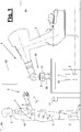
- Figure 1 shows a schematic representation of such a working device (1) in the form of a robot station.
- the moving automatic machine is designed here as an industrial robot (2) which has a plurality of driven and a plurality of links which are connected to one another in a movable, in particular articulated manner and which is connected to a robot controller (28).
- the industrial robot (2) can have any number and combination of rotary and / or translatory robot axes. According to Figure 1 e.g. as Articulated or articulated arm robots with five or more robot axes.
- the industrial robot (2) can have position-controlled or -controlled robot axes. Alternatively, it can be designed as a tactile industrial robot suitable for HRC with flexible, force-controlled or -controlled robot axes. A combined position and force control or regulation of the robot axes is also possible.
- the industrial robot (2) carries a robot tool (27) on its output member, for example a multi-axis robot hand, with which a workpiece (29) is machined on a support or the like.
- the industrial robot (2) has a work area in which collisions with an in Figure 1 represented workers (3) can occur.
- the worker (3) is, for example, a process observer who only observes the work process carried out by the robot (2). If necessary, he can also carry out accompanying process activities, such as feeding or checking workpieces (29) or the like.
- the working device (1) can be surrounded by a protective device (30), e.g. is designed as a fence and has an access opening for the worker (3).
- a protective device e.g. is designed as a fence and has an access opening for the worker (3).
- An industrial robot (2) is shown and described in the exemplary embodiments.
- another moving automatic machine with a work area that may be at risk of collision for example a loading device, an auxiliary device supporting the process, a transport device, a processing machine or the like can be present.
- the movements and positions of such moved automatic machine can be detected in a suitable manner, for example optically.
- the descriptions and explanations for the industrial robot (2) apply accordingly to other moving machines.
- the safety device (4) has a mobile detection device (5) which is carried by the worker (3) and which serves to locate the worker (3).
- the worker (3) can in particular carry the detection device (5) directly on his body, with his hands free for other activities.
- the term wearing is understood to mean any type of carrying and assignment of the detection device to the worker (3) and his body.
- the safety device (4) also has an evaluation and control device (6) which is in a communication connection (7) with the detection device (5).
- This is preferably a wireless communication link (7), in particular a radio link.
- the detection device (5) and the evaluation and control device (6) have corresponding communication units (11, 18) for this.
- the communication link (7) can be unidirectional or bidirectional.
- the detection device (5) transmits the localization data to the evaluation and control device (6).
- the evaluation and control device (6) can be arranged stationary. It is located within the communication area.
- the safety device (4) also has an interface (8), by means of which data about the current danger zone of the industrial robot (2) and / or another moving machine is recorded and processed in the evaluation and control device (6) can be. These data can originate from a detection device (20), which can optionally be part of the safety device (4) or which can also be assigned to the working device (1). Another input option is via a data connection to the robot controller (28) and / or another machine controller. The acquisition of data on the current danger zone is discussed in more detail below.
- the interface (8) can be connected to the evaluation and control device (6) or integrated into it.
- the evaluation and control device (6) can compare the data of the detection device (5) and the aforementioned data about the current danger area of the industrial robot (2) and can detect an existing or impending collision between worker (3) and industrial robot (2). Preventive detection of impending collisions is preferred.
- the evaluation and control device (6) can issue a warning signal. You can do this, for example, with a display (19), for example an Figure 1 displayed monitor. On the other hand, it can also trigger an emergency stop of the robot (2) via the interface (8) and the connection to the robot controller (28). Alternatively or additionally, it can also transmit a warning signal to the worker (3) according to the invention.
- the warning signals are body-specific and indicate to the worker the body part at risk of collision. This will be discussed in more detail below.
- the safety device (4) detects the spatial position and any movement of the worker (3) and communicates this to the evaluation and control device
- the position and movement detection is body-specific and takes place on several parts of the body of the worker (3). In particular, particularly collision-prone parts of the body, in particular the limbs (arms and legs), can be detected.
- the safety device (4) also has a reference device (17) for referencing the detection device (5).
- a reference device (17) for referencing the detection device (5).
- the detection device (5) can also be referenced here.
- the detection device (5) preferably has a plurality of mobile detection modules (9). These are assigned to several relevant body parts of the worker (3), in particular the aforementioned limbs. They record the spatial position and any movements of the part of the body concerned.
- the detection device (5) has nine mobile detection modules (9) which are assigned to the two lower and upper arms and the two lower and thighs and the torso of the worker (3).
- One or more further mobile detection modules (9) can also be assigned to other parts of the body, for example the hands, the head or the like.
- One or more other mobile acquisition modules (9) can be on the torso and / or on others Body parts can be arranged. There are also other mixed forms.
- the detection modules (9) are preferably worn on the body.
- a suitable carrying device (16) is provided, which can be adapted to the body and which enables the detection modules (9) to be specifically assigned to the desired body parts.
- the detection modules (9) can be attached and worn individually on the body with bands or the like.
- the carrying device (16) is preferably designed for accommodating the detection modules (9) in groups or as a whole.
- the carrying device (16) is designed as a safety suit, in particular as an overall.
- the safety suit (16), in particular overalls, has independent inventive significance.
- the carrying device (16), in particular the safety suit, can have a receptacle for each detection module (9), e.g. a suit pocket, which enables the desired body part assignment and allows trouble-free taking of the acquisition module (9).
- the receptacles can be open or closed, in particular the detection modules (9) can be sewn into prepared pocket-shaped receptacles.
- the detection modules (9) can each have their own and carried energy supply, in particular a battery.
- a separate energy supply (13) is provided, which is designed, for example, as a battery with a higher capacity and which is connected to the various detection modules (9) via lines (14).
- This connection can be releasable, for example push buttons (15) being arranged on the line ends and the detection modules (9) and on the power supply (13).
- the detection modules (9) each have a unidirectional or bidirectional communication unit (11), in particular a radio unit, for communication with the evaluation and control device (6) and its communication unit (18).
- a radio connection (7) other wireless communication connections are possible, e.g. by infrared, ultrasound or the like.
- a wired communication connection (7) is also possible.
- the signaling can be coupled to the detection device (5).
- the detection modules (9) preferably each have a signal unit (12) for signaling a collision or risk of collision to the worker (3).
- a signal unit (12) is preferably designed as a haptic or tactile unit, in particular as a vibration unit.
- a vibration signal can be recorded reliably and reliably by the worker (3) despite difficult environmental and working conditions and its meaning can be understood.
- the respective acquisition module (9) is up close in a suitable, e.g. pocket-like receptacle of the carrying device (16), in particular the safety suit.
- the aforementioned bidirectional communication link (7) enables the evaluation and control device (6) to specifically address the signal unit (12) of the detection module (9) on the part of the body affected by the risk of collision.
- This modular structure of the detection device (5) and the targeted addressing of the body part allow the worker (3) to react intuitively, specifically and correctly and to avoid the impending collision, for example by an evasive movement, in particular a withdrawal of the affected body part.
- the signal unit (12) can be designed in a different way and emit a different type of warning signal. It is possible e.g. optical and / or acoustic training, e.g. as a turn signal, horn or the like. Signaling is also electrical, e.g. with an electrical impulse, as possible with an electric shock.
- the signal unit (12) can only be present on a detection module (9) and signal a general risk of collision without further specification of a body part.
- a signal unit (12) on the detection device (5) can be dispensed with.
- a signal device of the safety device (4) for emitting warning signals in the event of a collision or danger can contain the aforementioned display (19) and / or a signal unit (12), possibly in a multiple arrangement.
- the warning signal in particular the vibration signal, can have a signal intensity or signal strength which is dependent on the distance between the worker and the machine. The smaller the distance and the greater the risk of collision, the higher it is.
- the detection modules (9) each have a sensor (10) for detecting the spatial position and any movement of the assigned body part.
- a sensor (10) can be designed in different ways. It can also exist more than once.
- the sensor (10) is designed as an inertial sensor.
- Such a sensor is based on inertia. For example, it may include an inertial accelerometer and / or an inertial gyroscope, or a combination of both. Alternatives are other suitable sensors (10) for three-dimensional position detection and for spatial movement detection are possible.
- the sensor (10) is connected to the communication unit (11) for signal transmission.
- the evaluation and control device (6) contains a computing unit and memory for one or more programs, data or the like. There are also input and output interfaces for data. Such a connection exists to the interface (8) mentioned, to the reference device (17) and possibly to the display (19).
- the evaluation and control device (6) has a program for creating a personal safety skeleton (22). This is also referred to as the human safety skeleton or abbreviated as PSS or HSS. It is created from the transmitted data of the detection device (5) and in particular of the detection modules (9).
- the PSS (22) is virtual and depicts the body parts, especially the torso and limbs, ie arms and legs.
- the skeleton division can be selected according to the division and arrangement of the acquisition modules (9).
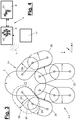
- Figure 3 shows a variant with torso and both sides lower and upper arms and lower and thighs. The skeletal limbs are symbolized, for example, by their articulated connections and connecting lines.
- the PSS (22) represents a virtual body model of the worker (3). It can also symbolize the arrangement and distribution of the acquisition modules (9).
- the PSS also has a virtual envelope area (25) for each relevant body part, in particular the limb, with a safety distance from the relevant core area of the limb.
- the PSS also has on at least one, preferably all model members one or more spatial vectors (24) which symbolize the movement of the body part detected in each case.
- the PSS, in particular the outer skin of the envelope areas (25) and the Vectors (24) are used for hazard analysis and for predicting possible collisions with the industrial robot (2).
- the vectors (24) and also the spatial movements of the body part mentioned in the description relate to the direction and the speed and, if appropriate, the acceleration of the movement. These data are also recorded accordingly by the respective sensor (10).
- the PSS (22) can furthermore have, on one or more limbs of the body model, a pre-warning area (26) for the limb or body part concerned which is expanded in the direction of movement (vector (24)). This pre-warning area (26) extends beyond the envelope area (25).
- the envelope area (25) can represent the actual dimensions of the limb or body part in question.
- the envelope area (25) can be expanded or enlarged by a certain safety distance beyond the actual dimensions. The safety distance can be used to compensate for computing or reaction times or other delays with an appropriate response to an existing or impending risk of collision.
- Said pre-warning area (26) can be pushed further out and can include a stronger apron detection.
- the evaluation and control device (6) can also have a program for creating a personal security skeleton (23), abbreviated MSS.
- An MSS created in another way can alternatively be transmitted to the evaluation and control device (6) via the interface (8) become.
- the current position and the displacement movement of the industrial robot (2) is determined mathematically from the MSS, whereby this determination can also be carried out individually for the robot members or with specific consideration of potential danger points of the robot (2) during the current movement.
- the position and movement of the worker (3) and his body parts as well as the positions and movements of the industrial robot (2) and his body parts are recorded and processed permanently or at a high frequency.
- This position and movement data of the industrial robot (2) and / or another moving machine can be generated in different ways.
- the aforementioned detection device (20) can be used for this. This can be stationary or non-stationary. It can also have a modular design and have one or more detection modules (21).
- a stationary detection device (20) can be, for example, an optical detection device, in particular a camera system.
- the detection device (20) is constructed similarly to the detection device (5), the detection module (21) having the same or a similar design as a detection module (9) and at least one such sensor (10) and one preferably wireless and has unidirectionally or bidirectionally communicating communication unit (11).
- the interface (8) can have a corresponding communication unit.
- the existing communication unit (18) of the evaluation and control device (6) can be used.
- a single detection module (21) is arranged on the robot tool (27).
- One or more further detection modules (21) can be arranged on one or more robot members.
- the MSS (23) can then be designed and generated in the same way as the previously described PSS (22).
- Corresponding or different detection modules (21) can also be used with another moving machine.
- position and movement data of the industrial robot (2) and its elements can be transmitted by the robot controller (28) via a bidirectional communication link and the interface (8).
- the MSS (23) can also be created from this data, including the robot dimensions.
- Mixed forms of robot data from the robot controller (28) and a detection device (20) with one or more detection modules (21) are also possible. The same applies to controls of other moving machines.
- the industrial robot (2) or the other moving automatic machine mentioned at the beginning can carry out any processes.
- This can be a joining process, e.g. welding, soldering, gluing or the like. Handling or assembly processes, application processes or the like are also possible.
- the safety device (4) or the signal device can alternatively or additionally be designed and function in a different way.
- You can, for example, in the afore-mentioned manner in the event of danger, a warning signal by means of a display (19) acoustically and / optically, for example on an in Figure 1 shown monitor, emit.
- the warning signal is also body-specific and signals to the worker the body part at risk of collision.
- the signaling device (31) can also activate a mechanical warning device, for example a barrier.
Landscapes
- Engineering & Computer Science (AREA)
- Mechanical Engineering (AREA)
- Robotics (AREA)
- General Engineering & Computer Science (AREA)
- Multimedia (AREA)
- Manipulator (AREA)
Description
Die Erfindung betrifft eine Sicherheitseinrichtung und ein Sicherheitsverfahren für Werker im Arbeitsbereich von automatischen Maschinen, insbesondere Industrierobotern, mit den Merkmalen im Oberbegriff der Verfahrens- und Vorrichtungshauptansprüche.The invention relates to a safety device and a safety method for workers in the work area of automatic machines, in particular industrial robots, with the features in the preamble of the main method and device claims.
Eine solche Sicherheitstechnik ist aus der
Aus der Praxis ist es ferner bekannt, den Arbeitsraum eines Roboters optisch zu überwachen, z.B. durch ein Kamerasystem, um etwaige Kollisionsgefahren zwischen dem Roboter und einem Werker oder einem anderen Hindernis zu detektieren und den Roboter rechtzeitig abzuschalten. Ferner ist es bekannt für eine Mensch-Roboter-Kooperation oder -Kolaboration (abgekürzt MRK) einen taktilen Roboter einzusetzen.It is also known in practice to optically monitor the working space of a robot, e.g. by a camera system to detect possible collision risks between the robot and a worker or another obstacle and to switch off the robot in good time. It is also known for a human-robot cooperation or collaboration (abbreviated MRK) to use a tactile robot.
Es ist Aufgabe der vorliegenden Erfindung, die Sicherheitstechnik für einen Werker weiter zu verbessern.It is an object of the present invention to further improve the safety technology for a worker.
Die Erfindung löst diese Aufgabe mit den Merkmalen in den Verfahrens- und Vorrichtungshauptansprüchen.The invention solves this problem with the features in the main method and device claims.
Die beanspruchte Sicherheitstechnik, insbesondere die Sicherheitseinrichtung und das Sicherheitsverfahren, bieten einem Werker eine erhöhte Sicherheit. Die Sicherheitstechnik setzt vornehmlich am Werker an, der mittels einer mobilen und vom Werker zu tragenden Erfassungseinrichtung lokalisiert werden kann. Die erfassten Daten können von einer Auswerte- und Steuereinrichtung verarbeitet werden, wobei auch die über eine Schnittstelle eingegebenen Daten über den aktuellen Gefahrenbereich eines Industrieroboters oder einer anderer bewegten automatischen Maschine einbezogen werden. Diese Daten über den aktuellen Gefahrenbereich können mittels einer zur Sicherheitseinrichtung gehörenden Detektionseinrichtung aufgenommen und bereit gestellt werden. Sie können alternativ auch anderweitig detektiert und zugeführt werden.The claimed safety technology, in particular the safety device and the safety procedure, offer a worker increased safety. The safety technology primarily applies to the worker, who can be localized by means of a mobile detection device to be carried by the worker. The Data recorded can be processed by an evaluation and control device, the data entered via an interface also being included about the current danger zone of an industrial robot or another moving automatic machine. This data about the current danger zone can be recorded and made available by means of a detection device belonging to the safety device. Alternatively, they can also be detected and supplied in another way.
Die Sicherheitstechnik erlaubt es, aus den vom Werker erfassten Daten und den vom Industrieroboter oder dergleichen detektierten Gefahrendaten eine bestehende oder drohende Kollisionsgefahr zu ermitteln und hieraus gegebenenfalls weitere Aktionen abzuleiten, z.B. die Ausgabe eines Signals, ein Nothalt des Roboters oder dergleichen.The safety technology makes it possible to determine an existing or impending risk of collision from the data recorded by the worker and the danger data detected by the industrial robot or the like and, if necessary, to derive further actions, e.g. the output of a signal, an emergency stop of the robot or the like.
Die Erfassungseinrichtung kann modular ausgebildet sein, wobei die räumlichen Positionen und gegebenenfalls die Bewegungen einzelner relevanter Körperteile des Werkers gezielt erfasst und zur Kollisions- und Gefahrenanalyse herangezogen werden können. Insbesondere kann aus diesen körperspezifischen Daten ein Personen-Sicherheits-Skelett erstellt und für die Kollisions- und Gefahrenanalyse herangezogen werden. In diesem aus den Erfassungsdaten aufbereiteten virtuellen Skelett sind einerseits die relevanten Körperteile, insbesondere die Gliedmaßen, simuliert und auch in ihrer eventuellen Bewegung durch einen dreidimensionalen Vektor charakterisiert. Zudem können die Skelettteile, insbesondere die Gliedmaßen, von einem Hüllbereich mit einem Sicherheitsabstand umgeben sein, der ebenfalls virtuell ist und der in einem Rechenmodell auf eine eventuelle Kollision mit einem Roboter oder dergleichen überprüft wird. Der Roboter oder dergleichen kann durch ein Maschinen-Sicherheits-Skelett entsprechender Art und gegebenenfalls auch mit ein oder mehreren Bewegungsvektoren und ein oder mehreren Hüllbereichen, symbolisiert sein. Durch die Hüllbereiche können Kollisionen rechtzeitig und unter Einbeziehung der erforderlichen Reaktionszeiten bzw. Verarbeitungsverzögerungen erfasst werden. Außerdem ist die Generierung eines Vorwarnbereichs durch gezielte Ausdehnung von einer oder mehreren Hüllbereichen in Bewegungsrichtung möglich.The detection device can be of modular design, the spatial positions and, if appropriate, the movements of individual relevant body parts of the worker being detected in a targeted manner and used for collision and hazard analysis. In particular, a personal safety skeleton can be created from this body-specific data and used for the collision and hazard analysis. In this virtual skeleton prepared from the acquisition data, the relevant body parts, in particular the limbs, are simulated on the one hand and their possible movement is also characterized by a three-dimensional vector. In addition, the skeletal parts, in particular the limbs, can be surrounded by an envelope area with a safety distance, which is also virtual and which is checked in a computing model for a possible collision with a robot or the like. The robot or the like can be made through a machine safety skeleton of a corresponding type and possibly also with one or more motion vectors and one or more envelope areas. Through the envelope areas, collisions can be recorded in good time, taking into account the required reaction times or processing delays. In addition, the generation of a pre-warning area is possible by targeted expansion of one or more envelope areas in the direction of movement.
Mit der Sicherheitseinrichtung kann permanent die räumliche Position und eine eventuelle Bewegung des Werkers erfasst und auf Kollisionen oder auf Kollisionsgefahren überwacht werden. Dies ist für alle Arten von Werkern und deren Tätigkeiten von Vorteil. Besondere Vorteile bestehen bei einem Prozessbeobachter.With the safety device, the spatial position and any movement of the worker can be continuously recorded and monitored for collisions or collision risks. This is advantageous for all types of workers and their activities. A process observer has special advantages.
Die Signalisierung von Kollisionen oder Kollisionsgefahren kann auf unterschiedliche Weise erfolgen. Von besonderem Vorteil ist eine direkte Rückmeldung an den Werker, was auf unterschiedliche Weise erfolgen kann. Erfindungsgemäß erfolgt eine körperspezifische Rückmeldung, die dem Werker auch das betroffene Körperteil signalisiert. Hierfür ist der modulare Aufbau der Erfassungseinrichtung und die Zuordnung der Erfassungsmodule zu mehreren relevanten Körperteilen, insbesondere Gliedmaßen, von Vorteil. Eine Rückmeldung kann insbesondere durch eine Vibration des Erfassungsmoduls erfolgen, was in Anbetracht des Arbeitsumfelds für den Werker besonders sicher und eindeutig bemerkbar ist. Er weiß dabei auch sofort und intuitiv, welches Körperteil betroffen ist.Collisions or collision risks can be signaled in different ways. Direct feedback to the worker is particularly advantageous, which can be done in different ways. According to the invention there is body-specific feedback, which also signals the affected part of the body to the worker. The modular structure of the detection device and the assignment of the detection modules to several relevant body parts, in particular limbs, are advantageous for this. A feedback can be given in particular by a vibration of the recording module, which is particularly safe and clearly noticeable for the worker in view of the work environment. He also knows immediately and intuitively which part of the body is affected.
Die Anordnung der Erfassungsmodule am Körper des Werkers kann mit einer geeigneten Trageeinrichtung erfolgen, die in unterschiedlicher Weise ausgebildet sein kann, z.B. als Gurtsystem, als Weste oder dergleichen. Besondere Vorteile bietet ein Sicherheitsanzug, insbesondere ein Overall, der auch sonstige Sicherheitsanforderungen erfüllt und der insbesondere an spezifischen Körperstellen Aufnahmen für ein Erfassungsmodul haben kann. Er erleichtert auch die Unterbringung einer geeigneten Energieversorgung nebst Leitungsnetzwerk.The detection modules can be arranged on the body of the worker using a suitable carrying device, which can be designed in different ways, for example as a belt system, as a vest or the like. A safety suit, in particular overalls, offers particular advantages also meets other security requirements and which can have recordings for a recording module, in particular at specific parts of the body. It also makes it easier to accommodate a suitable energy supply and line network.
Der Sicherheitsanzug, insbesondere Overall, hat eigenständige erfinderische Bedeutung. Der Sicherheitsanzug weist eine oder mehrere bevorzugt taschenartige Aufnahmen für oder mit einer Erfassungseinrichtung zur Lokalisierung des Werkers auf. Der Sicherheitsanzug hat insbesondere mehrere im Bereich der Körpergliedmaßen angeordnete Aufnahmen für jeweils ein Erfassungsmodul und ggf. eine Aufnahme für eine Energieversorgung. Die Aufnahmen können offen oder verschlossen sein, insbesondere können die Erfassungsmodule in vorbereitete taschenförmige Aufnahmen eingenäht sein.The safety suit, especially overalls, has independent inventive significance. The safety suit has one or more preferably pocket-like receptacles for or with a detection device for localizing the worker. The safety suit has, in particular, a plurality of receptacles arranged in the area of the limbs, each for a detection module and possibly a receptacle for an energy supply. The receptacles can be open or closed, in particular the acquisition modules can be sewn into prepared pocket-shaped receptacles.
In den Unteransprüchen sind weitere vorteilhafte Ausgestaltungen der Erfindung angegeben.Further advantageous refinements of the invention are specified in the subclaims.
Die Erfindung ist in den Zeichnungen beispielhaft und schematisch dargestellt. Im Einzelnen zeigen:
- Figur 1:
- eine Arbeitsvorrichtung mit einem Roboter, einem Werker und einer Sicherheitseinrichtung,
- Figur 2:
- eine schematische Darstellung der Sicherheitseinrichtung und ihrer Erfassungseinrichtung mit Körperbezug,
- Figur 3:
- eine schematische Darstellung eines Personen-Sicherheits-Skeletts und
- Figur 4:
- eine schematische Darstellung einer Auswerte- und Steuereinrichtung.
- Figure 1:
- a working device with a robot, a worker and a safety device,
- Figure 2:
- 1 shows a schematic representation of the safety device and its detection device with body reference,
- Figure 3:
- a schematic representation of a personal security skeleton and
- Figure 4:
- is a schematic representation of an evaluation and control device.
Die Erfindung betrifft eine Sicherheitseinrichtung (4) und ein Sicherheitsverfahren für einen Werker (3) im Arbeitsbereich von bewegten automatischen Maschinen (2), insbesondere Industrierobotern. Die Erfindung betrifft ferner eine mit einer solchen Sicherheitseinrichtung (4) ausgerichtete Arbeitsvorrichtung (1), z.B. eine Roboterstation.The invention relates to a safety device (4) and a safety method for a worker (3) in the working area of moving automatic machines (2), in particular industrial robots. The invention further relates to a working device (1) aligned with such a safety device (4), e.g. a robot station.
Der Industrieroboter (2) kann eine beliebige Zahl und Kombination von rotatorischen und/oder translatorischen Roboterachsen haben. Er kann gemäß
An seinem Abtriebsglied, z.B. einer mehrachsigen Roboterhand, trägt der Industrieroboter (2) ein Roboterwerkzeug (27), mit dem ein Werkstück (29) auf einer Auflage oder dergleichen bearbeitet wird. Der Industrieroboter (2) hat einen Arbeitsbereich, in dem Kollisionen mit einem in
In der Arbeitsvorrichtung (1) können auch mehrere Industrieroboter (2) angeordnet sein. Die Arbeitsvorrichtung (1) kann von einer Schutzvorrichtung (30) umgeben sein, die z.B. als Zaun ausgebildet ist und eine Zugangsöffnung für den Werker (3) aufweist.Several industrial robots (2) can also be arranged in the working device (1). The working device (1) can be surrounded by a protective device (30), e.g. is designed as a fence and has an access opening for the worker (3).
In den Ausführungsbeispielen ist ein Industrieroboter (2) dargestellt und beschrieben. Alternativ oder zusätzlich kann eine andere bewegte automatische Maschine mit einem evtl. kollisionsgefährdeten Arbeitsbereich, z.B. eine Ladevorrichtung, eine den Prozess unterstützende Hilfsvorrichtung, eine Transportvorrichtung, eine Bearbeitungsmaschine oder dgl. vorhanden sein. Die Bewegungen und Positionen einer solchen bewegten automatischen Maschine können in geeigneter Weise, z.B. optisch, detektiert werden. Die Beschreibungen und Erläuterungen zum Industrieroboter (2) gelten entsprechend auch für andere bewegte Maschinen.An industrial robot (2) is shown and described in the exemplary embodiments. As an alternative or in addition, another moving automatic machine with a work area that may be at risk of collision, for example a loading device, an auxiliary device supporting the process, a transport device, a processing machine or the like can be present. The movements and positions of such moved automatic machine can be detected in a suitable manner, for example optically. The descriptions and explanations for the industrial robot (2) apply accordingly to other moving machines.
Die Sicherheitseinrichtung (4) weist eine mobile Erfassungseinrichtung (5) auf, die vom Werker (3) getragen wird und die zur Lokalisierung des Werkers (3) dient. Der Werker (3) kann die Erfassungseinrichtung (5) insbesondere direkt an seinem Körper tragen, wobei er die Hände frei hat für andere Tätigkeiten. Unter dem Begriff eines Tragens wird jegliche Art von Mitführung und Zuordnung der Erfassungseinrichtung zum Werker (3) und seinem Körper verstanden.The safety device (4) has a mobile detection device (5) which is carried by the worker (3) and which serves to locate the worker (3). The worker (3) can in particular carry the detection device (5) directly on his body, with his hands free for other activities. The term wearing is understood to mean any type of carrying and assignment of the detection device to the worker (3) and his body.
Die Sicherheitseinrichtung (4) weist ferner eine Auswerte-und Steuereinrichtung (6) auf, die mit der Erfassungseinrichtung (5) in einer Kommunikationsverbindung (7) steht. Dies ist bevorzugt eine drahtlose Kommunikationsverbindung (7), insbesondere eine Funkverbindung. Die Erfassungseinrichtung (5) und die Auswerte- und Steuereinrichtung (6) haben hierfür entsprechende Kommunikationseinheiten (11,18). Die Kommunikationsverbindung (7) kann unidirektional oder bidirektional sein. Insbesondere werden von der Erfassungseinrichtung (5) die Lokalisierungsdaten an die Auswerte- und Steuereinrichtung (6) übermittelt.The safety device (4) also has an evaluation and control device (6) which is in a communication connection (7) with the detection device (5). This is preferably a wireless communication link (7), in particular a radio link. The detection device (5) and the evaluation and control device (6) have corresponding communication units (11, 18) for this. The communication link (7) can be unidirectional or bidirectional. In particular, the detection device (5) transmits the localization data to the evaluation and control device (6).
Die Auswerte- und Steuereinrichtung (6) kann stationär angeordnet sein. Sie befindet sich innerhalb des Kommunikationsbereichs.The evaluation and control device (6) can be arranged stationary. It is located within the communication area.
Die Sicherheitseinrichtung (4) weist ferner eine Schnittstelle (8) auf, mittels der Daten über den aktuellen Gefahrenbereich des Industrieroboters (2) und/oder einer anderen bewegten Maschine aufgenommen und in der Auswerte- und Steuereinrichtung (6) verarbeitet werden können. Diese Daten können von einer Detektionseinrichtung (20) stammen, die gegebenenfalls Bestandteil der Sicherheitseinrichtung (4) sein kann oder die auch der Arbeitsvorrichtung (1) zugeordnet sein kann. Eine andere Eingabemöglichkeit besteht über eine Datenverbindung mit der Robotersteuerung (28) und/oder einer anderen Maschinensteuerung. Über die Erfassung der Daten über den aktuellen Gefahrenbereich wird nachstehend noch näher eingegangen. Die Schnittstelle (8) kann an die Auswerte- und Steuereinrichtung (6) angeschlossen oder in diese integriert sein.The safety device (4) also has an interface (8), by means of which data about the current danger zone of the industrial robot (2) and / or another moving machine is recorded and processed in the evaluation and control device (6) can be. These data can originate from a detection device (20), which can optionally be part of the safety device (4) or which can also be assigned to the working device (1). Another input option is via a data connection to the robot controller (28) and / or another machine controller. The acquisition of data on the current danger zone is discussed in more detail below. The interface (8) can be connected to the evaluation and control device (6) or integrated into it.
Die Auswerte- und Steuereinrichtung (6) kann die Daten der Erfassungseinrichtung (5) und die vorerwähnten Daten über den aktuellen Gefahrenbereich des Industrieroboters (2) vergleichen und hieraus eine bestehende oder drohende Kollision von Werker (3) und Industrieroboter (2) detektieren. Bevorzugt geht es um die vorbeugende Detektion von drohenden Kollisionen.The evaluation and control device (6) can compare the data of the detection device (5) and the aforementioned data about the current danger area of the industrial robot (2) and can detect an existing or impending collision between worker (3) and industrial robot (2). Preventive detection of impending collisions is preferred.
Auf Grund des Detektionsergebnisses können weitere Reaktionen oder Prozesse ausgelöst werden. Insbesondere kann die Auswerte- und Steuereinrichtung (6) ein Warnsignal ausgeben. Sie kann hierfür z.B. mit einer Anzeige (19), z.B. einem in
Die Sicherheitseinrichtung (4) erfasst die räumliche Position und eine eventuelle Bewegung des Werkers (3) und kommuniziert dies an die Auswerte- und SteuereinrichtungThe safety device (4) detects the spatial position and any movement of the worker (3) and communicates this to the evaluation and control device
(6). Diese wertet die Daten zur erwähnten Gefahrenanalyse aus. Die Positions- und Bewegungserfassung ist körperspezifisch und erfolgt an mehreren Körperstellen des Werkers (3). Insbesondere können dabei besonders kollisionsträchtige Körperteile, insbesondere die Gliedmaßen (Arme und Beine) erfasst werden.(6). This evaluates the data for the hazard analysis mentioned. The position and movement detection is body-specific and takes place on several parts of the body of the worker (3). In particular, particularly collision-prone parts of the body, in particular the limbs (arms and legs), can be detected.
Die Sicherheitseinrichtung (4) weist ferner eine Referenzeinrichtung (17) für die Referenzierung der Erfassungseinrichtung (5) auf. Hierüber kann einerseits eine Erkennung der Anwesenheit eines Werkers (3) und einer Erfassungseinrichtung (5) und eine entsprechende Initialisierung der Auswerte- und Steuereinrichtung (6) veranlasst werden. Andererseits kann hierüber auch die Erfassungseinrichtung (5) referenziert werden.The safety device (4) also has a reference device (17) for referencing the detection device (5). On the one hand, the presence of a worker (3) and a detection device (5) and a corresponding initialization of the evaluation and control device (6) can be initiated. On the other hand, the detection device (5) can also be referenced here.
Die Erfassungseinrichtung (5) weist vorzugsweise mehrere mobile Erfassungsmodule (9) auf. Diese sind mehreren relevanten Körperteilen des Werkers (3), insbesondere den vorerwähnten Gliedmaßen, zugeordnet. Sie nehmen die räumliche Position und eventuelle Bewegungen des betreffenden Körperteils auf.The detection device (5) preferably has a plurality of mobile detection modules (9). These are assigned to several relevant body parts of the worker (3), in particular the aforementioned limbs. They record the spatial position and any movements of the part of the body concerned.
Wie
Die Erfassungsmodule (9) werden bevorzugt am Körper getragen. Hierfür ist eine geeignete Trageinrichtung (16) vorgesehen, die an den Körper angepasst sein kann und die eine gezielte Zuordnung der Erfassungsmodule (9) zu den jeweils gewünschten Körperteilen ermöglicht. Die Erfassungsmodule (9) können einzeln am Körper mit Bändern oder dgl. befestigt und getragen werden. Bevorzugt ist die Trageinrichtung (16) für eine gruppenweise oder insgesamte Unterbringung der Erfassungsmodule (9) ausgebildet.The detection modules (9) are preferably worn on the body. For this purpose, a suitable carrying device (16) is provided, which can be adapted to the body and which enables the detection modules (9) to be specifically assigned to the desired body parts. The detection modules (9) can be attached and worn individually on the body with bands or the like. The carrying device (16) is preferably designed for accommodating the detection modules (9) in groups or as a whole.
Im gezeigten Ausführungsbeispiel ist die Trageinrichtung (16) als Sicherheitsanzug, insbesondere als Overall, ausgebildet. Der Sicherheitsanzug (16), insbesondere Overall, hat eigenständige erfinderische Bedeutung.In the exemplary embodiment shown, the carrying device (16) is designed as a safety suit, in particular as an overall. The safety suit (16), in particular overalls, has independent inventive significance.
Die Trageinrichtung (16), insbesondere der Sicherheitsanzug, kann für jedes Erfassungsmodul (9) eine Aufnahme aufweisen, z.B. eine Anzugtasche, welche die gewünschte Körperteilzuordnung ermöglicht und ein störungsfreies Mitnehmen des Erfassungsmoduls (9) erlaubt. Die Aufnahmen können offen oder verschlossen sein, insbesondere können die Erfassungsmodule (9) in vorbereitete taschenförmige Aufnahmen eingenäht sein.The carrying device (16), in particular the safety suit, can have a receptacle for each detection module (9), e.g. a suit pocket, which enables the desired body part assignment and allows trouble-free taking of the acquisition module (9). The receptacles can be open or closed, in particular the detection modules (9) can be sewn into prepared pocket-shaped receptacles.
Die Erfassungsmodule (9) können jeweils eine eigene und mitgeführte Energieversorgung, insbesondere eine Batterie, aufweisen. Im gezeigten und bevorzugten Ausführungsbeispiel ist eine separate Energieversorgung (13) vorgesehen, die z.B. als Batterie mit höherer Kapazität ausgebildet ist und die mit den verschiedenen Erfassungsmodulen (9) über Leitungen (14) verbunden ist. Diese Verbindung kann lösbar sein, wobei z.B. Druckknöpfe (15) an den Leitungsenden und den Erfassungsmodulen (9) sowie an der Energieversorgung (13) angeordnet sind.The detection modules (9) can each have their own and carried energy supply, in particular a battery. In the exemplary embodiment shown and preferred, a separate energy supply (13) is provided, which is designed, for example, as a battery with a higher capacity and which is connected to the various detection modules (9) via lines (14). This connection can be releasable, for example push buttons (15) being arranged on the line ends and the detection modules (9) and on the power supply (13).
Die Erfassungsmodule (9) weisen jeweils eine uni- oder bidirektionale Kommunikationseinheit (11), insbesondere eine Funkeinheit, für die Kommunikation mit der Auswerte-und Steuereinrichtung (6) und deren Kommunikationseinheit (18) auf. Statt einer Funkverbindung (7) sind andere drahtlose Kommunikationsverbindungen möglich, z.B. per Infrarot, Ultraschall oder dergleichen. Auch eine leitungsgebundene Kommunikationsverbindung (7) ist möglich.The detection modules (9) each have a unidirectional or bidirectional communication unit (11), in particular a radio unit, for communication with the evaluation and control device (6) and its communication unit (18). Instead of a radio connection (7), other wireless communication connections are possible, e.g. by infrared, ultrasound or the like. A wired communication connection (7) is also possible.
Die Signalisierung kann mit der Erfassungseinrichtung (5) gekoppelt sein. Die Erfassungsmodule (9) weisen vorzugsweise jeweils eine Signaleinheit (12) zur Signalisierung einer Kollision oder Kollisionsgefahr an den Werker (3) auf. Eine solche Signaleinheit (12) ist vorzugsweise als haptische oder taktile Einheit, insbesondere als Vibrationseinheit, ausgebildet. Ein Vibrationssignal kann vom Werker (3) zuverlässig und unterscheidungssicher trotz schwieriger Umgebungs- und Arbeitsbedingungen aufgenommen werden und in seinem Bedeutungsinhalt verstanden werden. Das jeweilige Erfassungsmodul (9) ist hierfür hautnah in einer geeigneten, z.B. taschenartigen Aufnahme der Trageinrichtung (16), insbesondere des Sicherheitsanzugs, untergebracht.The signaling can be coupled to the detection device (5). The detection modules (9) preferably each have a signal unit (12) for signaling a collision or risk of collision to the worker (3). Such a signal unit (12) is preferably designed as a haptic or tactile unit, in particular as a vibration unit. A vibration signal can be recorded reliably and reliably by the worker (3) despite difficult environmental and working conditions and its meaning can be understood. For this purpose, the respective acquisition module (9) is up close in a suitable, e.g. pocket-like receptacle of the carrying device (16), in particular the safety suit.
Durch die erwähnte bidirektionale Kommunikationsverbindung (7) kann die Auswerte- und Steuereinrichtung (6) gezielt die Signaleinheit (12) des Erfassungsmoduls (9) an dem von der Kollisionsgefahr betroffenen Körperteil ansprechen. Dieser modulare Aufbau der Erfassungseinrichtung (5) und die gezielte Körperteilansprache erlaubt es dem Werker (3) intuitiv, gezielt und richtig zu reagieren und die drohende Kollision zu vermeiden, z.B. durch eine Ausweichbewegung, insbesondere ein Rückziehen des betroffenen Körperteils.The aforementioned bidirectional communication link (7) enables the evaluation and control device (6) to specifically address the signal unit (12) of the detection module (9) on the part of the body affected by the risk of collision. This modular structure of the detection device (5) and the targeted addressing of the body part allow the worker (3) to react intuitively, specifically and correctly and to avoid the impending collision, for example by an evasive movement, in particular a withdrawal of the affected body part.
Alternativ oder zusätzlich kann die Signaleinheit (12) in anderer Weise ausgebildet sein und eine andere Art von Warnsignal emittieren. Möglich ist z.B. eine optische und/oder akustische Ausbildung, z.B. als Blinker, Hupe oder dgl.. Eine Signalisierung ist auch auf elektrischem weg, z.B. mit einem elektrischen Impuls, wie bei einem Elektroschock möglich.Alternatively or additionally, the signal unit (12) can be designed in a different way and emit a different type of warning signal. It is possible e.g. optical and / or acoustic training, e.g. as a turn signal, horn or the like. Signaling is also electrical, e.g. with an electrical impulse, as possible with an electric shock.
In einer anderen Ausführungsform kann die Signaleinheit (12) nur an einem Erfassungsmodul (9) vorhanden sein und ohne nähere Spezifikation eines Körperteils eine allgemeine Kollisionsgefahr signalisieren. In einer weiteren Abwandlung kann auf eine Signaleinheit (12) an der Erfassungseinrichtung (5) verzichtet werden.In another embodiment, the signal unit (12) can only be present on a detection module (9) and signal a general risk of collision without further specification of a body part. In a further modification, a signal unit (12) on the detection device (5) can be dispensed with.
Eine Signaleinrichtung der Sicherheitseinrichtung (4) zur Abgabe von Warnsignalen im Kollisions- oder Gefahrenfall kann die vorgenannte Anzeige (19) und/oder eine Signaleinheit (12) ggf. in Mehrfachanordnung beinhalten.A signal device of the safety device (4) for emitting warning signals in the event of a collision or danger can contain the aforementioned display (19) and / or a signal unit (12), possibly in a multiple arrangement.
Das Warnsignal, insbesondere das Vibrationssignal, kann eine Signalintensität bzw. Signalstärke aufweisen, die abhängig von der Entfernung zwischen Werker und Maschine ist. Sie ist umso höher, je kleiner die Entfernung und je größer die Kollisionsgefahr ist.The warning signal, in particular the vibration signal, can have a signal intensity or signal strength which is dependent on the distance between the worker and the machine. The smaller the distance and the greater the risk of collision, the higher it is.
Die Erfassungsmodule (9) weisen jeweils einen Sensor (10) für die Erfassung der räumlichen Position und einer evtl. Bewegung des zugeordneten Körperteils auf. Ein solcher Sensor (10) kann in unterschiedlicher Weise ausgebildet sein. Er kann auch mehrfach vorhanden sein. Im gezeigten und bevorzugten Ausführungsbeispiel ist der Sensor (10) als Inertialsensor ausgebildet. Ein derartiger Sensor basiert auf Trägheit. Er kann z.B. einen inertialen Beschleunigungsmesser und/oder ein Inertialgyroskop oder eine Kombination von beiden beinhalten. Alternativ sind andere geeignete Sensoren (10) zur dreidimensionalen Positionserfassung und zur räumlichen Bewegungserfassung möglich. Der Sensor (10) ist zur Signalübermittlung mit der Kommunikationseinheit (11) verbunden.The detection modules (9) each have a sensor (10) for detecting the spatial position and any movement of the assigned body part. Such a sensor (10) can be designed in different ways. It can also exist more than once. In the exemplary embodiment shown and preferred, the sensor (10) is designed as an inertial sensor. Such a sensor is based on inertia. For example, it may include an inertial accelerometer and / or an inertial gyroscope, or a combination of both. Alternatives are other suitable sensors (10) for three-dimensional position detection and for spatial movement detection are possible. The sensor (10) is connected to the communication unit (11) for signal transmission.
Die Auswerte- und Steuereinrichtung (6) beinhaltet eine Recheneinheit und Speicher für ein oder mehrere Programme, Daten oder dergleichen. Ferner sind Eingabe- und Ausgabeschnittstellen für Daten vorhanden. Eine solche Verbindung besteht zur erwähnten Schnittstelle (8), zur Referenzeinrichtung (17) und ggf. zur Anzeige (19). Die Auswerte- und Steuereinrichtung (6) weist ein Programm zur Erstellung eines Personen-Sicherheits-Skeletts (22) auf. Dieses wird auch als Human-Safety-Skelett oder abgekürzt als PSS oder HSS bezeichnet. Es wird aus den übermittelten Daten der Erfassungseinrichtung (5) und insbesondere der Erfassungsmodule (9) erstellt. Das PSS (22) ist virtuell und bildet die Körperteile, insbesondere den Torso und die Gliedmaßen, d.h. Arme und Beine, ab. Die Skelettaufteilung kann entsprechend der Aufteilung und Anordnung der Erfassungsmodule (9) gewählt werden.
Das PSS (22) stellt ein virtuelles Körpermodell des Werkers (3) dar. Es kann zugleich die Anordnung und Verteilung der Erfassungsmodule (9) symbolisieren. Das PSS hat außerdem zu jedem relevanten Körperteil, insbesondere Glied, einen virtuellen Hüllbereich (25) mit einem Sicherheitsabstand zu dem betreffenden Kernbereich des Glieds. Das PSS weist ferner an mindestens einem, vorzugsweise allen Modellgliedern eine oder mehrere räumliche Vektoren (24) auf, welche die Bewegung des jeweils erfassten Körperteils symbolisieren. Das PSS, insbesondere die Außenhaut der Hüllbereiche (25) und die Vektoren (24) werden zur Gefahrenanalyse und zur Vorausberechnung evtl. Kollisionen mit dem Industrieroboter (2) herangezogen. Die Vektoren (24) und auch die in der Beschreibung vorerwähnten räumlichen Bewegungen des Körperteils betreffen die Richtung und die Geschwindigkeit sowie ggf. die Beschleunigung der Bewegung. Diese Daten werden auch entsprechend von dem jeweiligen Sensor (10) erfasst.The PSS (22) represents a virtual body model of the worker (3). It can also symbolize the arrangement and distribution of the acquisition modules (9). The PSS also has a virtual envelope area (25) for each relevant body part, in particular the limb, with a safety distance from the relevant core area of the limb. The PSS also has on at least one, preferably all model members one or more spatial vectors (24) which symbolize the movement of the body part detected in each case. The PSS, in particular the outer skin of the envelope areas (25) and the Vectors (24) are used for hazard analysis and for predicting possible collisions with the industrial robot (2). The vectors (24) and also the spatial movements of the body part mentioned in the description relate to the direction and the speed and, if appropriate, the acceleration of the movement. These data are also recorded accordingly by the respective sensor (10).
Das PSS (22) kann ferner an ein oder mehreren Gliedern des Körpermodels einen in Bewegungsrichtung (Vektor (24)) erweiterten Vorwarnbereich (26) für das betreffende Glied bzw. Körperteil aufweisen. Dieser Vorwarnbereich (26) geht über den Hüllbereich (25) hinaus.The PSS (22) can furthermore have, on one or more limbs of the body model, a pre-warning area (26) for the limb or body part concerned which is expanded in the direction of movement (vector (24)). This pre-warning area (26) extends beyond the envelope area (25).
Der Hüllbereich (25) kann in einer Variante die tatsächlichen Abmessungen des betreffenden Glieds oder Körperteils repräsentieren. In einer anderen Ausführung kann der Hüllbereich (25) über die tatsächlichen Abmessungen hinaus um einen gewissen Sicherheitsabstand erweitert oder vergrößert sein. Der Sicherheitsabstand kann der Kompensation von Rechen- oder Reaktionszeiten oder sonstigen Verzögerung bei einer angemessenen Reaktion auf eine bestehende oder drohende Kollisionsgefahr dienen. Der besagte Vorwarnbereich (26) kann noch weiter hinausgeschoben sein und kann eine stärkere Vorfelderfassung beinhalten. Durch rechnerische Projektion der aktuellen Ruhelage oder der Bewegung des betreffenden Körperteils kann vorausschauend ermittelt werden, ob auf diesem Bewegungsweg in näherer Zukunft eine Kollision mit dem ggf. bewegten Industrieroboter (2) stattfinden kann.In one variant, the envelope area (25) can represent the actual dimensions of the limb or body part in question. In another embodiment, the envelope area (25) can be expanded or enlarged by a certain safety distance beyond the actual dimensions. The safety distance can be used to compensate for computing or reaction times or other delays with an appropriate response to an existing or impending risk of collision. Said pre-warning area (26) can be pushed further out and can include a stronger apron detection. By mathematical projection of the current rest position or the movement of the body part in question, it can be determined in advance whether a collision with the possibly moving industrial robot (2) can take place in the near future.
Die Auswerte- und Steuereinrichtung (6) kann auch ein Programm zur Erstellung eines Personen-Sicherheits-Skeletts (23), abgekürzt MSS, aufweisen. Ein anderweitig erstelltes MSS kann alternativ über die Schnittstelle (8) an die Auswerte- und Steuereinrichtung (6) übermittelt werden.The evaluation and control device (6) can also have a program for creating a personal security skeleton (23), abbreviated MSS. An MSS created in another way can alternatively be transmitted to the evaluation and control device (6) via the interface (8) become.
Die aktuelle Lage und die Verlagerungsbewegung des Industrieroboters (2) wird aus dem MSS rechnerisch ermittelt, wobei diese Ermittlung auch für die Roboterglieder einzeln bzw. mit spezifischer Berücksichtung von potenziellen Gefährdungsstellen des Roboters (2) bei der aktuellen Bewegung erfolgen kann. Position und Bewegung des Werkers (3) und seiner Körperteile sowie die Positionen und Bewegungen des Industrieroboters (2) und seiner Körperteile werden permanent bzw. mit einem hochfrequenten Takt erfasst und verarbeitet.The current position and the displacement movement of the industrial robot (2) is determined mathematically from the MSS, whereby this determination can also be carried out individually for the robot members or with specific consideration of potential danger points of the robot (2) during the current movement. The position and movement of the worker (3) and his body parts as well as the positions and movements of the industrial robot (2) and his body parts are recorded and processed permanently or at a high frequency.
Diese Positions- und Bewegungsdaten des Industrieroboters (2) und/oder einer anderen bewegten Maschine können in unterschiedlicher Weise generiert werden. Einerseits kann hierfür die vorerwähnte Detektionseinrichtung (20) eingesetzt werden. Diese kann stationär oder instationär ausgebildet sein. Sie kann ferner eine modulare Ausbildung besitzen und ein oder mehrere Detektionsmodule (21) aufweisen.This position and movement data of the industrial robot (2) and / or another moving machine can be generated in different ways. On the one hand, the aforementioned detection device (20) can be used for this. This can be stationary or non-stationary. It can also have a modular design and have one or more detection modules (21).
Eine stationäre Detektionseinrichtung (20) kann z.B. eine optische Erfassungseinrichtung, insbesondere ein Kamerasystem, sein. In der gezeigten Ausführungsform ist die Detektionseinrichtung (20) ähnlich wie die Erfassungseinrichtung (5) aufgebaut, wobei das Detektionsmodul (21) eine gleiche oder ähnliche Ausbildung wie ein Erfassungsmodul (9) haben kann und zumindest einen solchen Sensor (10) und eine bevorzugt drahtlos und uni-oder bidirektional kommunizierende Kommunikationseinheit (11) aufweist. Die Schnittstelle (8) kann eine entsprechende Kommunikationseinheit haben. Alternativ kann die vorhandene Kommunikationseinheit (18) der Auswerte-und Steuereinrichtung (6) benutzt werden.A stationary detection device (20) can be, for example, an optical detection device, in particular a camera system. In the embodiment shown, the detection device (20) is constructed similarly to the detection device (5), the detection module (21) having the same or a similar design as a detection module (9) and at least one such sensor (10) and one preferably wireless and has unidirectionally or bidirectionally communicating communication unit (11). The interface (8) can have a corresponding communication unit. Alternatively, the existing communication unit (18) of the evaluation and control device (6) can be used.
In
In weiterer Abwandlung können Positions- und Bewegungsdaten des Industrieroboters (2) und seiner Glieder von der Robotersteuerung (28) über eine bidirektionale Kommunikationsverbindung und die Schnittstelle (8) übermittelt werden. Aus diesen Daten kann ebenfalls das MSS (23) unter Einbeziehung der Roboterabmessung erstellt werden. Ferner sind Mischformen aus Roboterdaten von der Robotersteuerung (28) und einer Detektionseinrichtung (20) mit ein oder mehreren Detektionsmodulen (21) möglich. Entsprechendes gilt für Steuerungen von anderen bewegten Maschinen.In a further modification, position and movement data of the industrial robot (2) and its elements can be transmitted by the robot controller (28) via a bidirectional communication link and the interface (8). The MSS (23) can also be created from this data, including the robot dimensions. Mixed forms of robot data from the robot controller (28) and a detection device (20) with one or more detection modules (21) are also possible. The same applies to controls of other moving machines.
Der Industrieroboter (2) oder die eingangserwähnte andere bewegte automatische Maschine kann beliebige Prozesse durchführen. Dies kann ein Fügeprozess, z.B. ein Schweißen, Löten, Kleben oder dergleichen sein. Ferner sind Handhabungs- oder Montageprozesse, Auftragprozesse oder dergleichen möglich.The industrial robot (2) or the other moving automatic machine mentioned at the beginning can carry out any processes. This can be a joining process, e.g. welding, soldering, gluing or the like. Handling or assembly processes, application processes or the like are also possible.
Abwandlungen der gezeigten oder beschriebenen Ausführungsformen sind in verschiedener Weise möglich. Insbesondere können die Merkmale der vorstehenden Ausführungsbeispiele und ihrer Abwandlungen beliebig miteinander kombiniert und ggf. auch vertauscht werden.Modifications of the embodiments shown or described are possible in various ways. In particular, the features of the above exemplary embodiments and their modifications can be combined with one another as desired and, if appropriate, also exchanged.
Die Sicherheitseinrichtung (4) bzw. die Signaleinrichtung kann alternativ oder zusätzlich in anderer Weise ausgebildet sein und funktionieren. Sie kann z.B. in der vorerwähnten Weise im Gefahrenfall ein Warnsignal mittels einer Anzeige (19) akustisch und/optisch, z.B. auf einem in
- 11
- Arbeitsvorrichtung, RoboterstationWorking device, robot station
- 22nd
- automatische Maschine, Industrieroboterautomatic machine, industrial robot
- 33rd
- Werker, ProzessbeobachterWorker, process observer
- 44th
- SicherheitseinrichtungSafety device
- 55
- Erfassungseinrichtung, SensoreinrichtungDetection device, sensor device
- 66
- Auswerte- und SteuereinrichtungEvaluation and control device
- 77
- Kommunikationsverbindung, FunkverbindungCommunication link, radio link
- 88th
- Schnittstelleinterface
- 99
- Erfassungsmodul, GliedmaßenmodulDetection module, limb module
- 1010th
- Sensor, InertialsensorSensor, inertial sensor
- 1111
- KommunikationseinheitCommunication unit
- 1212th
- Signaleinheit, VibrationseinheitSignal unit, vibration unit
- 1313
- Energieversorgung, BatteriePower supply, battery
- 1414
- Leitungmanagement
- 1515
- DruckknopfPush button
- 1616
- Trageinrichtung, SicherheitsanzugCarrying device, safety suit
- 1717th
- Referenzeinrichtung, ReferenzsensorReference device, reference sensor
- 1818th
- KommunikationseinheitCommunication unit
- 1919th
- Anzeige, MonitorDisplay, monitor
- 2020
- Detektionseinrichtung für GefahrenbereichDetection device for danger area
- 2121
- DetektionsmodulDetection module
- 2222
- Personen-Sicherheits-Skelett, PSSPersonal Security Skeleton, PSS
- 2323
- Maschinen-Sicherheits-Skelett, MSSMachine safety skeleton, MSS
- 2424th
- Vektorvector
- 2525th
- Hüllbereich, WarnbereichEnvelope area, warning area
- 2626
- VorwarnbereichAdvance warning area
- 2727
- RoboterwerkzeugRobot tool
- 2828
- RobotersteuerungRobot control
- 2929
- Werkstückworkpiece
- 3030th
- Schutzvorrichtung, ZaunProtection device, fence
Claims (15)
- Safety device for workers (3) in the working area of moving automatic machines (2), in particular industrial robots, wherein the safety device (4) permanently captures the spatial position and a possible movement of the worker and monitors for collisions or risks of collision and has a mobile capture device (5), which is to be worn by the worker (3) and is intended to locate the worker (3), and an evaluation and control device (6), wherein the devices (5, 6) have a preferably wireless communication connection, and the evaluation and control device (6) also has an interface (8) for inputting data relating to the current hazardous area of the automatic machine (2), in particular the industrial robot, characterized in that, in the event of a collision or a risk of collision, the safety device (4) transmits a warning signal to the worker (3), wherein the safety device (4) provides the worker (3) with body-specific feedback and signals the affected body part.
- Safety device according to Claim 1, characterized in that the warning signal has a signal intensity or signal strength which is dependent on the distance between the worker and the moving machine (2) and, in particular, is higher, the shorter the distance and the greater the risk of collision.
- Safety device according to Claim 1 or 2, characterized in that the capture device (5) captures the spatial position and possibly movements of the worker (3) and communicates them to the evaluation and control device (6), wherein the evaluation and control device (6) compares the data from the capture device (5) and the data relating to the current hazardous area of the automatic machine (2), in particular the industrial robot, and detects an existing or imminent collision of the worker (3) and the automatic machine (2), in particular the industrial robot, and outputs a warning signal via a signal unit (12) or a display (19) if a collision or a risk of collision is detected.
- Safety device according to Claim 1, 2 or 3, characterized in that the capture device (5) has a plurality of mobile capture modules (9) which can be assigned to a plurality of relevant body parts, in particular limbs, of the worker (3) and record the spatial position and possibly movements of the relevant body part.
- Safety device according to one of the preceding claims, characterized in that a capture module (9) has a signal unit (12) for signalling a collision or a risk of collision to the worker (3), wherein the signal unit (12) is preferably in the form of a haptic or tactile unit, in particular a vibration unit, or in the form of an optical and/or acoustic unit.
- Safety device according to one of the preceding claims, characterized in that the capture modules (9) each have a sensor (10), in particular an inertial sensor, for capturing the spatial position and possibly movements of the relevant body part.
- Safety device according to one of the preceding claims, characterized in that the safety device (4) has a carrying device (16), in particular a safety suit, which can be worn on the body, for the capture device (5), in particular for the capture modules (9), and possibly an energy supply (13).
- Safety device according to one of the preceding claims, characterized in that the evaluation and control device (6) has a computing unit and a program for creating a personal safety skeleton (22) from the data from the capture device (5) and a program for creating a machine safety skeleton (23) from the received data relating to the current hazardous area of the automatic machine (2), in particular the industrial robot.
- Working apparatus having a moving automatic machine (2), in particular an industrial robot, characterized in that the working apparatus (1) has a safety device (4) for workers (3) that is designed according to at least one of Claims 1 to 8.
- Safety method for workers (3) in the working area of moving automatic machines (2), in particular industrial robots, wherein a safety device (4) is used to permanently capture the spatial position and a possible movement of the worker and to monitor for collisions or risks of collision, wherein the safety device (4) has a mobile capture device (5), which is worn by the worker (3) and is intended to locate the worker (3), and an evaluation and control device (6), wherein the devices (5, 6) have a preferably wireless communication connection, and the evaluation and control device (6) also has an interface (8) for inputting data relating to the current hazardous area of the automatic machine (2), in particular the industrial robot, characterized in that, in the event of a collision or a risk of collision, a warning signal is transmitted to the worker (3), wherein, in the event of a collision or a risk of collision, the worker (3) is provided with body-specific feedback and the affected body part is signalled.
- Safety method according to Claim 10, characterized in that the spatial positions and possibly the movements of individual relevant body parts of the worker (3) are deliberately captured using a modular capture device (5) and are used for collision and risk analysis.
- Safety method according to Claim 10 or 11, characterized in that the capture device (5), in particular its capture modules (9), is worn directly on the body of the worker (3) and is assigned to the relevant body parts, wherein, in the event of a collision or a risk of collision, a warning signal is transmitted to the worker (3) by means of a haptic or tactile signal unit (12) of a capture module (9).
- Safety method according to one of Claims 10 to 12, characterized in that a virtual personal safety skeleton (22) is created from captured body-specific data relating to the worker (3) and is used for collision and risk analysis, wherein the skeleton parts, in particular the limbs, are surrounded by a virtual envelope area (25) with a safety distance, which is checked in a computational model for a possible collision with an automatic machine (2).
- Safety method according to one of Claims 10 to 13, characterized in that the moving machine (2) is symbolized using one or more motion vectors and envelope areas (25), wherein collisions are captured in good time and with the inclusion of the required response times or processing delays by means of the envelope areas (25).
- Safety method according to one of Claims 10 to 14, characterized in that an advance warning area is generated by deliberately expanding one or more envelope areas (25) in the direction of movement.
Applications Claiming Priority (2)
| Application Number | Priority Date | Filing Date | Title |
|---|---|---|---|
| DE202014100411.4U DE202014100411U1 (en) | 2014-01-30 | 2014-01-30 | safety device |
| PCT/EP2015/051917 WO2015114089A1 (en) | 2014-01-30 | 2015-01-30 | Safety device and safety process |
Publications (2)
| Publication Number | Publication Date |
|---|---|
| EP3099452A1 EP3099452A1 (en) | 2016-12-07 |
| EP3099452B1 true EP3099452B1 (en) | 2020-08-05 |
Family
ID=52484439
Family Applications (1)
| Application Number | Title | Priority Date | Filing Date |
|---|---|---|---|
| EP15705216.8A Active EP3099452B1 (en) | 2014-01-30 | 2015-01-30 | Safety device and safety process |
Country Status (3)
| Country | Link |
|---|---|
| EP (1) | EP3099452B1 (en) |
| DE (1) | DE202014100411U1 (en) |
| WO (1) | WO2015114089A1 (en) |
Families Citing this family (20)
| Publication number | Priority date | Publication date | Assignee | Title |
|---|---|---|---|---|
| US10422870B2 (en) * | 2015-06-15 | 2019-09-24 | Humatics Corporation | High precision time of flight measurement system for industrial automation |
| US10099374B2 (en) | 2015-12-01 | 2018-10-16 | Bragi GmbH | Robotic safety using wearables |
| DE102016200455A1 (en) * | 2016-01-15 | 2017-07-20 | Fraunhofer-Gesellschaft zur Förderung der angewandten Forschung e.V. | Safety device and method for safe operation of a robot |
| DE102016004902A1 (en) * | 2016-04-22 | 2017-10-26 | Kuka Roboter Gmbh | Monitoring a robot |
| DE102016007519A1 (en) * | 2016-06-20 | 2017-12-21 | Kuka Roboter Gmbh | Monitoring a system with at least one robot |
| CN106003047B (en) * | 2016-06-28 | 2019-01-22 | 北京光年无限科技有限公司 | A kind of danger early warning method and apparatus towards intelligent robot |
| DE102017119149A1 (en) | 2016-09-20 | 2018-03-22 | Mayser Holding Gmbh & Co. Kg | Method for contactless detection of relatively moving objects and sensor device |
| DE202017106201U1 (en) * | 2017-10-12 | 2019-01-16 | Wilhelm Altendorf Gmbh & Co. Kg | Safety device for machine tools |
| DE102017010718A1 (en) * | 2017-11-17 | 2019-05-23 | Kuka Deutschland Gmbh | Method and means for operating a robot arrangement |
| DE102017129959A1 (en) * | 2017-12-14 | 2019-04-25 | Schaeffler Technologies AG & Co. KG | Method of operating a system with multiple machines |
| CN111491766A (en) * | 2017-12-21 | 2020-08-04 | 麦格纳国际公司 | Safety control module for robot assembly and method thereof |
| DE102018208609A1 (en) * | 2018-05-30 | 2019-12-05 | Siemens Aktiengesellschaft | A method of operating a wireless communication link and system arrangement |
| EP3956109A1 (en) * | 2019-04-16 | 2022-02-23 | ABB Schweiz AG | Method of handling safety, control system and industrial system |
| DE102019206010A1 (en) * | 2019-04-26 | 2020-10-29 | Kuka Aktiengesellschaft | Method and system for monitoring a robot arrangement |
| DE102019211770B3 (en) * | 2019-08-06 | 2020-09-03 | BIBA - Bremer Institut für Produktion und Logistik GmbH | Process for the computer-aided recording and evaluation of a workflow in which a human worker and a robotic system interact |
| CN112847430B (en) * | 2019-11-26 | 2022-03-29 | 中国科学院沈阳自动化研究所 | Intrinsic safety design method for cooperative robot |
| CN112917475B (en) * | 2021-01-27 | 2022-05-20 | 哈尔滨工程大学 | Safe nursing control method for assisting eating by eating assisting robot based on multiple perceptions |
| CN114434444B (en) * | 2022-01-27 | 2023-08-08 | 南京航空航天大学 | Planning method for auxiliary assembly safety space of heavy-duty industrial robot |
| CN114924513B (en) * | 2022-06-07 | 2023-06-06 | 中迪机器人(盐城)有限公司 | Multi-robot cooperative control system and method |
| DE102022131352A1 (en) | 2022-11-28 | 2024-05-29 | Schaeffler Technologies AG & Co. KG | Method for controlling a robot collaborating with a human and system with a collaborative robot |
Family Cites Families (7)
| Publication number | Priority date | Publication date | Assignee | Title |
|---|---|---|---|---|
| DE10152543A1 (en) * | 2001-10-24 | 2003-05-08 | Sick Ag | Method and device for controlling a safety-relevant function of a machine |
| DE10216023B4 (en) | 2002-04-11 | 2013-08-14 | Fraunhofer-Gesellschaft zur Förderung der angewandten Forschung e.V. | Method and apparatus for controlled interaction between a self-propelled robot unit and a human |
| DE102004048563A1 (en) * | 2004-10-04 | 2006-04-13 | Benteler Automobiltechnik Gmbh | Monitoring system for an industrial robot prevents collision with objects within field of operation |
| DE102007007576B4 (en) * | 2007-02-15 | 2009-01-15 | Kuka Roboter Gmbh | Method and device for securing a working space |
| DE102007037077B4 (en) * | 2007-08-06 | 2019-02-21 | Kuka Roboter Gmbh | Method for maintaining working space limits of a working means of a robot |
| DE102009046107A1 (en) | 2009-10-28 | 2011-05-05 | Ifm Electronic Gmbh | System and method for interaction between a person and a machine |
| CN104428107B (en) * | 2012-07-10 | 2016-06-29 | 西门子公司 | The method that robot arranges and is used for controlling robot |
-
2014
- 2014-01-30 DE DE202014100411.4U patent/DE202014100411U1/en not_active Expired - Lifetime
-
2015
- 2015-01-30 EP EP15705216.8A patent/EP3099452B1/en active Active
- 2015-01-30 WO PCT/EP2015/051917 patent/WO2015114089A1/en active Application Filing
Non-Patent Citations (1)
| Title |
|---|
| None * |
Also Published As
| Publication number | Publication date |
|---|---|
| EP3099452A1 (en) | 2016-12-07 |
| WO2015114089A1 (en) | 2015-08-06 |
| DE202014100411U1 (en) | 2015-05-05 |
Similar Documents
| Publication | Publication Date | Title |
|---|---|---|
| EP3099452B1 (en) | Safety device and safety process | |
| US9981394B2 (en) | Workstation | |
| DE112011101930B4 (en) | Method, control system and movement specification means for programming or specifying movements or sequences of an industrial robot | |
| DE10361132B4 (en) | Method for monitoring the movement of a moving in several degrees of freedom moving danger object of a handling device, such as handling mass and / or movable mass | |
| DE202013104860U1 (en) | working device | |
| EP3365142B1 (en) | Protective-field adjustment of a manipulator system | |
| EP3321070A1 (en) | Unpacking device for unpacking an additively manufactured three-dimensional object from the surrounding construction material | |
| EP3321010B1 (en) | Unpacking device for unpacking an additively manufactured three-dimensional object from the surrounding construction material | |
| US20130178980A1 (en) | Anti-collision system for moving an object around a congested environment | |
| EP2324967A2 (en) | System and method for recognising collisions in automated production or assembly machines | |
| DE102016200455A1 (en) | Safety device and method for safe operation of a robot | |
| DE102006044071B4 (en) | Robot as well as robot protection device | |
| DE102013001987A1 (en) | Method for detecting human and moving objects working in hybrid working system used for cleaning of soiled article, determines movement of human and moving object according to spatial distribution of radio frequency identification tags | |
| DE10320343A1 (en) | Method for monitored cooperation between robot unit and human operator e.g. for industry, involves impressing movement pattern on to robot during approach to human operator | |
| DE102013110901B4 (en) | HRC planning technology | |
| DE202014010054U1 (en) | Protektofon - a cognitive safety function | |
| DE10216023A1 (en) | A method for controlling the interface between a robot movement and a person within the working area has the operator fitted with transmitting units to establish a pattern of movements. | |
| EP3148863A1 (en) | Plug-setting device | |
| DE202015101427U1 (en) | mounter | |
| EP3224681B1 (en) | System for virtual commissioning | |
| DE202013105910U1 (en) | robot tool | |
| EP2577414A2 (en) | Method and control system for programming or specifying motions or sequences of an industrial robot | |
| AT510658A1 (en) | MOBILE OPERATOR | |
| EP2724825A2 (en) | Device for carrying out a sequence of movements | |
| EP2625008B1 (en) | Control of a robot |
Legal Events
| Date | Code | Title | Description |
|---|---|---|---|
| PUAI | Public reference made under article 153(3) epc to a published international application that has entered the european phase |
Free format text: ORIGINAL CODE: 0009012 |
|
| STAA | Information on the status of an ep patent application or granted ep patent |
Free format text: STATUS: REQUEST FOR EXAMINATION WAS MADE |
|
| 17P | Request for examination filed |
Effective date: 20160823 |
|
| AK | Designated contracting states |
Kind code of ref document: A1 Designated state(s): AL AT BE BG CH CY CZ DE DK EE ES FI FR GB GR HR HU IE IS IT LI LT LU LV MC MK MT NL NO PL PT RO RS SE SI SK SM TR |
|
| AX | Request for extension of the european patent |
Extension state: BA ME |
|
| DAX | Request for extension of the european patent (deleted) | ||
| GRAP | Despatch of communication of intention to grant a patent |
Free format text: ORIGINAL CODE: EPIDOSNIGR1 |
|
| STAA | Information on the status of an ep patent application or granted ep patent |
Free format text: STATUS: GRANT OF PATENT IS INTENDED |
|
| INTG | Intention to grant announced |
Effective date: 20200420 |
|
| GRAS | Grant fee paid |
Free format text: ORIGINAL CODE: EPIDOSNIGR3 |
|
| GRAA | (expected) grant |
Free format text: ORIGINAL CODE: 0009210 |
|
| STAA | Information on the status of an ep patent application or granted ep patent |
Free format text: STATUS: THE PATENT HAS BEEN GRANTED |
|
| AK | Designated contracting states |
Kind code of ref document: B1 Designated state(s): AL AT BE BG CH CY CZ DE DK EE ES FI FR GB GR HR HU IE IS IT LI LT LU LV MC MK MT NL NO PL PT RO RS SE SI SK SM TR |
|
| REG | Reference to a national code |
Ref country code: GB Ref legal event code: FG4D Free format text: NOT ENGLISH |
|
| REG | Reference to a national code |
Ref country code: CH Ref legal event code: EP |
|
| REG | Reference to a national code |
Ref country code: AT Ref legal event code: REF Ref document number: 1298069 Country of ref document: AT Kind code of ref document: T Effective date: 20200815 |
|
| REG | Reference to a national code |
Ref country code: DE Ref legal event code: R096 Ref document number: 502015013167 Country of ref document: DE |
|
| REG | Reference to a national code |
Ref country code: IE Ref legal event code: FG4D Free format text: LANGUAGE OF EP DOCUMENT: GERMAN |
|
| REG | Reference to a national code |
Ref country code: LT Ref legal event code: MG4D |
|
| REG | Reference to a national code |
Ref country code: NL Ref legal event code: MP Effective date: 20200805 |
|
| PG25 | Lapsed in a contracting state [announced via postgrant information from national office to epo] |
Ref country code: BG Free format text: LAPSE BECAUSE OF FAILURE TO SUBMIT A TRANSLATION OF THE DESCRIPTION OR TO PAY THE FEE WITHIN THE PRESCRIBED TIME-LIMIT Effective date: 20201105 Ref country code: NO Free format text: LAPSE BECAUSE OF FAILURE TO SUBMIT A TRANSLATION OF THE DESCRIPTION OR TO PAY THE FEE WITHIN THE PRESCRIBED TIME-LIMIT Effective date: 20201105 Ref country code: HR Free format text: LAPSE BECAUSE OF FAILURE TO SUBMIT A TRANSLATION OF THE DESCRIPTION OR TO PAY THE FEE WITHIN THE PRESCRIBED TIME-LIMIT Effective date: 20200805 Ref country code: LT Free format text: LAPSE BECAUSE OF FAILURE TO SUBMIT A TRANSLATION OF THE DESCRIPTION OR TO PAY THE FEE WITHIN THE PRESCRIBED TIME-LIMIT Effective date: 20200805 Ref country code: SE Free format text: LAPSE BECAUSE OF FAILURE TO SUBMIT A TRANSLATION OF THE DESCRIPTION OR TO PAY THE FEE WITHIN THE PRESCRIBED TIME-LIMIT Effective date: 20200805 Ref country code: FI Free format text: LAPSE BECAUSE OF FAILURE TO SUBMIT A TRANSLATION OF THE DESCRIPTION OR TO PAY THE FEE WITHIN THE PRESCRIBED TIME-LIMIT Effective date: 20200805 Ref country code: GR Free format text: LAPSE BECAUSE OF FAILURE TO SUBMIT A TRANSLATION OF THE DESCRIPTION OR TO PAY THE FEE WITHIN THE PRESCRIBED TIME-LIMIT Effective date: 20201106 Ref country code: ES Free format text: LAPSE BECAUSE OF FAILURE TO SUBMIT A TRANSLATION OF THE DESCRIPTION OR TO PAY THE FEE WITHIN THE PRESCRIBED TIME-LIMIT Effective date: 20200805 Ref country code: PT Free format text: LAPSE BECAUSE OF FAILURE TO SUBMIT A TRANSLATION OF THE DESCRIPTION OR TO PAY THE FEE WITHIN THE PRESCRIBED TIME-LIMIT Effective date: 20201207 |
|
| PG25 | Lapsed in a contracting state [announced via postgrant information from national office to epo] |
Ref country code: IS Free format text: LAPSE BECAUSE OF FAILURE TO SUBMIT A TRANSLATION OF THE DESCRIPTION OR TO PAY THE FEE WITHIN THE PRESCRIBED TIME-LIMIT Effective date: 20201205 Ref country code: LV Free format text: LAPSE BECAUSE OF FAILURE TO SUBMIT A TRANSLATION OF THE DESCRIPTION OR TO PAY THE FEE WITHIN THE PRESCRIBED TIME-LIMIT Effective date: 20200805 Ref country code: PL Free format text: LAPSE BECAUSE OF FAILURE TO SUBMIT A TRANSLATION OF THE DESCRIPTION OR TO PAY THE FEE WITHIN THE PRESCRIBED TIME-LIMIT Effective date: 20200805 Ref country code: RS Free format text: LAPSE BECAUSE OF FAILURE TO SUBMIT A TRANSLATION OF THE DESCRIPTION OR TO PAY THE FEE WITHIN THE PRESCRIBED TIME-LIMIT Effective date: 20200805 Ref country code: NL Free format text: LAPSE BECAUSE OF FAILURE TO SUBMIT A TRANSLATION OF THE DESCRIPTION OR TO PAY THE FEE WITHIN THE PRESCRIBED TIME-LIMIT Effective date: 20200805 |
|
| PG25 | Lapsed in a contracting state [announced via postgrant information from national office to epo] |
Ref country code: EE Free format text: LAPSE BECAUSE OF FAILURE TO SUBMIT A TRANSLATION OF THE DESCRIPTION OR TO PAY THE FEE WITHIN THE PRESCRIBED TIME-LIMIT Effective date: 20200805 Ref country code: RO Free format text: LAPSE BECAUSE OF FAILURE TO SUBMIT A TRANSLATION OF THE DESCRIPTION OR TO PAY THE FEE WITHIN THE PRESCRIBED TIME-LIMIT Effective date: 20200805 Ref country code: SM Free format text: LAPSE BECAUSE OF FAILURE TO SUBMIT A TRANSLATION OF THE DESCRIPTION OR TO PAY THE FEE WITHIN THE PRESCRIBED TIME-LIMIT Effective date: 20200805 Ref country code: CZ Free format text: LAPSE BECAUSE OF FAILURE TO SUBMIT A TRANSLATION OF THE DESCRIPTION OR TO PAY THE FEE WITHIN THE PRESCRIBED TIME-LIMIT Effective date: 20200805 Ref country code: DK Free format text: LAPSE BECAUSE OF FAILURE TO SUBMIT A TRANSLATION OF THE DESCRIPTION OR TO PAY THE FEE WITHIN THE PRESCRIBED TIME-LIMIT Effective date: 20200805 |
|
| REG | Reference to a national code |
Ref country code: DE Ref legal event code: R097 Ref document number: 502015013167 Country of ref document: DE |
|
| PG25 | Lapsed in a contracting state [announced via postgrant information from national office to epo] |
Ref country code: AL Free format text: LAPSE BECAUSE OF FAILURE TO SUBMIT A TRANSLATION OF THE DESCRIPTION OR TO PAY THE FEE WITHIN THE PRESCRIBED TIME-LIMIT Effective date: 20200805 |
|
| PLBE | No opposition filed within time limit |
Free format text: ORIGINAL CODE: 0009261 |
|
| STAA | Information on the status of an ep patent application or granted ep patent |
Free format text: STATUS: NO OPPOSITION FILED WITHIN TIME LIMIT |
|
| PG25 | Lapsed in a contracting state [announced via postgrant information from national office to epo] |
Ref country code: SK Free format text: LAPSE BECAUSE OF FAILURE TO SUBMIT A TRANSLATION OF THE DESCRIPTION OR TO PAY THE FEE WITHIN THE PRESCRIBED TIME-LIMIT Effective date: 20200805 |
|
| 26N | No opposition filed |
Effective date: 20210507 |
|
| PG25 | Lapsed in a contracting state [announced via postgrant information from national office to epo] |
Ref country code: IT Free format text: LAPSE BECAUSE OF FAILURE TO SUBMIT A TRANSLATION OF THE DESCRIPTION OR TO PAY THE FEE WITHIN THE PRESCRIBED TIME-LIMIT Effective date: 20200805 |
|
| REG | Reference to a national code |
Ref country code: DE Ref legal event code: R119 Ref document number: 502015013167 Country of ref document: DE |
|
| PG25 | Lapsed in a contracting state [announced via postgrant information from national office to epo] |
Ref country code: MC Free format text: LAPSE BECAUSE OF FAILURE TO SUBMIT A TRANSLATION OF THE DESCRIPTION OR TO PAY THE FEE WITHIN THE PRESCRIBED TIME-LIMIT Effective date: 20200805 Ref country code: SI Free format text: LAPSE BECAUSE OF FAILURE TO SUBMIT A TRANSLATION OF THE DESCRIPTION OR TO PAY THE FEE WITHIN THE PRESCRIBED TIME-LIMIT Effective date: 20200805 |
|
| REG | Reference to a national code |
Ref country code: CH Ref legal event code: PL |
|
| GBPC | Gb: european patent ceased through non-payment of renewal fee |
Effective date: 20210130 |
|
| PG25 | Lapsed in a contracting state [announced via postgrant information from national office to epo] |
Ref country code: LU Free format text: LAPSE BECAUSE OF NON-PAYMENT OF DUE FEES Effective date: 20210130 |
|
| REG | Reference to a national code |
Ref country code: BE Ref legal event code: MM Effective date: 20210131 |
|
| PG25 | Lapsed in a contracting state [announced via postgrant information from national office to epo] |
Ref country code: FR Free format text: LAPSE BECAUSE OF NON-PAYMENT OF DUE FEES Effective date: 20210131 |
|
| PG25 | Lapsed in a contracting state [announced via postgrant information from national office to epo] |
Ref country code: GB Free format text: LAPSE BECAUSE OF NON-PAYMENT OF DUE FEES Effective date: 20210130 Ref country code: LI Free format text: LAPSE BECAUSE OF NON-PAYMENT OF DUE FEES Effective date: 20210131 Ref country code: DE Free format text: LAPSE BECAUSE OF NON-PAYMENT OF DUE FEES Effective date: 20210803 Ref country code: CH Free format text: LAPSE BECAUSE OF NON-PAYMENT OF DUE FEES Effective date: 20210131 |
|
| PG25 | Lapsed in a contracting state [announced via postgrant information from national office to epo] |
Ref country code: IE Free format text: LAPSE BECAUSE OF NON-PAYMENT OF DUE FEES Effective date: 20210130 |
|
| REG | Reference to a national code |
Ref country code: AT Ref legal event code: MM01 Ref document number: 1298069 Country of ref document: AT Kind code of ref document: T Effective date: 20210130 |
|
| PG25 | Lapsed in a contracting state [announced via postgrant information from national office to epo] |
Ref country code: AT Free format text: LAPSE BECAUSE OF NON-PAYMENT OF DUE FEES Effective date: 20210130 |
|
| PG25 | Lapsed in a contracting state [announced via postgrant information from national office to epo] |
Ref country code: IS Free format text: LAPSE BECAUSE OF FAILURE TO SUBMIT A TRANSLATION OF THE DESCRIPTION OR TO PAY THE FEE WITHIN THE PRESCRIBED TIME-LIMIT Effective date: 20201205 |
|
| PG25 | Lapsed in a contracting state [announced via postgrant information from national office to epo] |
Ref country code: BE Free format text: LAPSE BECAUSE OF NON-PAYMENT OF DUE FEES Effective date: 20210131 |
|
| PG25 | Lapsed in a contracting state [announced via postgrant information from national office to epo] |
Ref country code: HU Free format text: LAPSE BECAUSE OF FAILURE TO SUBMIT A TRANSLATION OF THE DESCRIPTION OR TO PAY THE FEE WITHIN THE PRESCRIBED TIME-LIMIT; INVALID AB INITIO Effective date: 20150130 |
|
| PG25 | Lapsed in a contracting state [announced via postgrant information from national office to epo] |
Ref country code: CY Free format text: LAPSE BECAUSE OF FAILURE TO SUBMIT A TRANSLATION OF THE DESCRIPTION OR TO PAY THE FEE WITHIN THE PRESCRIBED TIME-LIMIT Effective date: 20200805 |
|
| P01 | Opt-out of the competence of the unified patent court (upc) registered |
Effective date: 20230528 |
|
| PG25 | Lapsed in a contracting state [announced via postgrant information from national office to epo] |
Ref country code: MK Free format text: LAPSE BECAUSE OF FAILURE TO SUBMIT A TRANSLATION OF THE DESCRIPTION OR TO PAY THE FEE WITHIN THE PRESCRIBED TIME-LIMIT Effective date: 20200805 |