EP3099226B1 - Luminal impedance device with integrated circuit modules - Google Patents
Luminal impedance device with integrated circuit modules Download PDFInfo
- Publication number
- EP3099226B1 EP3099226B1 EP15743045.5A EP15743045A EP3099226B1 EP 3099226 B1 EP3099226 B1 EP 3099226B1 EP 15743045 A EP15743045 A EP 15743045A EP 3099226 B1 EP3099226 B1 EP 3099226B1
- Authority
- EP
- European Patent Office
- Prior art keywords
- sensor
- data
- power
- distal
- sizing
- Prior art date
- Legal status (The legal status is an assumption and is not a legal conclusion. Google has not performed a legal analysis and makes no representation as to the accuracy of the status listed.)
- Active
Links
Images


Classifications
-
- A—HUMAN NECESSITIES
- A61—MEDICAL OR VETERINARY SCIENCE; HYGIENE
- A61B—DIAGNOSIS; SURGERY; IDENTIFICATION
- A61B5/00—Measuring for diagnostic purposes; Identification of persons
- A61B5/05—Detecting, measuring or recording for diagnosis by means of electric currents or magnetic fields; Measuring using microwaves or radio waves
- A61B5/053—Measuring electrical impedance or conductance of a portion of the body
- A61B5/0538—Measuring electrical impedance or conductance of a portion of the body invasively, e.g. using a catheter
-
- A—HUMAN NECESSITIES
- A61—MEDICAL OR VETERINARY SCIENCE; HYGIENE
- A61B—DIAGNOSIS; SURGERY; IDENTIFICATION
- A61B5/00—Measuring for diagnostic purposes; Identification of persons
- A61B5/0002—Remote monitoring of patients using telemetry, e.g. transmission of vital signals via a communication network
- A61B5/0015—Remote monitoring of patients using telemetry, e.g. transmission of vital signals via a communication network characterised by features of the telemetry system
- A61B5/0022—Monitoring a patient using a global network, e.g. telephone networks, internet
-
- A—HUMAN NECESSITIES
- A61—MEDICAL OR VETERINARY SCIENCE; HYGIENE
- A61B—DIAGNOSIS; SURGERY; IDENTIFICATION
- A61B5/00—Measuring for diagnostic purposes; Identification of persons
- A61B5/01—Measuring temperature of body parts ; Diagnostic temperature sensing, e.g. for malignant or inflamed tissue
-
- A—HUMAN NECESSITIES
- A61—MEDICAL OR VETERINARY SCIENCE; HYGIENE
- A61B—DIAGNOSIS; SURGERY; IDENTIFICATION
- A61B5/00—Measuring for diagnostic purposes; Identification of persons
- A61B5/02—Detecting, measuring or recording for evaluating the cardiovascular system, e.g. pulse, heart rate, blood pressure or blood flow
- A61B5/0205—Simultaneously evaluating both cardiovascular conditions and different types of body conditions, e.g. heart and respiratory condition
- A61B5/02055—Simultaneously evaluating both cardiovascular condition and temperature
-
- A—HUMAN NECESSITIES
- A61—MEDICAL OR VETERINARY SCIENCE; HYGIENE
- A61B—DIAGNOSIS; SURGERY; IDENTIFICATION
- A61B5/00—Measuring for diagnostic purposes; Identification of persons
- A61B5/02—Detecting, measuring or recording for evaluating the cardiovascular system, e.g. pulse, heart rate, blood pressure or blood flow
- A61B5/021—Measuring pressure in heart or blood vessels
- A61B5/0215—Measuring pressure in heart or blood vessels by means inserted into the body
-
- A—HUMAN NECESSITIES
- A61—MEDICAL OR VETERINARY SCIENCE; HYGIENE
- A61B—DIAGNOSIS; SURGERY; IDENTIFICATION
- A61B5/00—Measuring for diagnostic purposes; Identification of persons
- A61B5/02—Detecting, measuring or recording for evaluating the cardiovascular system, e.g. pulse, heart rate, blood pressure or blood flow
- A61B5/026—Measuring blood flow
-
- A—HUMAN NECESSITIES
- A61—MEDICAL OR VETERINARY SCIENCE; HYGIENE
- A61B—DIAGNOSIS; SURGERY; IDENTIFICATION
- A61B5/00—Measuring for diagnostic purposes; Identification of persons
- A61B5/103—Measuring devices for testing the shape, pattern, colour, size or movement of the body or parts thereof, for diagnostic purposes
- A61B5/107—Measuring physical dimensions, e.g. size of the entire body or parts thereof
- A61B5/1076—Measuring physical dimensions, e.g. size of the entire body or parts thereof for measuring dimensions inside body cavities, e.g. using catheters
-
- A—HUMAN NECESSITIES
- A61—MEDICAL OR VETERINARY SCIENCE; HYGIENE
- A61B—DIAGNOSIS; SURGERY; IDENTIFICATION
- A61B5/00—Measuring for diagnostic purposes; Identification of persons
- A61B5/45—For evaluating or diagnosing the musculoskeletal system or teeth
- A61B5/4504—Bones
- A61B5/4509—Bone density determination
-
- A—HUMAN NECESSITIES
- A61—MEDICAL OR VETERINARY SCIENCE; HYGIENE
- A61B—DIAGNOSIS; SURGERY; IDENTIFICATION
- A61B5/00—Measuring for diagnostic purposes; Identification of persons
- A61B5/68—Arrangements of detecting, measuring or recording means, e.g. sensors, in relation to patient
- A61B5/6846—Arrangements of detecting, measuring or recording means, e.g. sensors, in relation to patient specially adapted to be brought in contact with an internal body part, i.e. invasive
- A61B5/6847—Arrangements of detecting, measuring or recording means, e.g. sensors, in relation to patient specially adapted to be brought in contact with an internal body part, i.e. invasive mounted on an invasive device
- A61B5/6851—Guide wires
-
- A—HUMAN NECESSITIES
- A61—MEDICAL OR VETERINARY SCIENCE; HYGIENE
- A61B—DIAGNOSIS; SURGERY; IDENTIFICATION
- A61B5/00—Measuring for diagnostic purposes; Identification of persons
- A61B5/68—Arrangements of detecting, measuring or recording means, e.g. sensors, in relation to patient
- A61B5/6846—Arrangements of detecting, measuring or recording means, e.g. sensors, in relation to patient specially adapted to be brought in contact with an internal body part, i.e. invasive
- A61B5/6847—Arrangements of detecting, measuring or recording means, e.g. sensors, in relation to patient specially adapted to be brought in contact with an internal body part, i.e. invasive mounted on an invasive device
- A61B5/6852—Catheters
- A61B5/6853—Catheters with a balloon
-
- A—HUMAN NECESSITIES
- A61—MEDICAL OR VETERINARY SCIENCE; HYGIENE
- A61B—DIAGNOSIS; SURGERY; IDENTIFICATION
- A61B5/00—Measuring for diagnostic purposes; Identification of persons
- A61B5/72—Signal processing specially adapted for physiological signals or for diagnostic purposes
- A61B5/7225—Details of analogue processing, e.g. isolation amplifier, gain or sensitivity adjustment, filtering, baseline or drift compensation
-
- A—HUMAN NECESSITIES
- A61—MEDICAL OR VETERINARY SCIENCE; HYGIENE
- A61B—DIAGNOSIS; SURGERY; IDENTIFICATION
- A61B2560/00—Constructional details of operational features of apparatus; Accessories for medical measuring apparatus
- A61B2560/02—Operational features
- A61B2560/0204—Operational features of power management
- A61B2560/0214—Operational features of power management of power generation or supply
-
- A—HUMAN NECESSITIES
- A61—MEDICAL OR VETERINARY SCIENCE; HYGIENE
- A61B—DIAGNOSIS; SURGERY; IDENTIFICATION
- A61B2560/00—Constructional details of operational features of apparatus; Accessories for medical measuring apparatus
- A61B2560/04—Constructional details of apparatus
- A61B2560/0406—Constructional details of apparatus specially shaped apparatus housings
-
- A—HUMAN NECESSITIES
- A61—MEDICAL OR VETERINARY SCIENCE; HYGIENE
- A61B—DIAGNOSIS; SURGERY; IDENTIFICATION
- A61B2560/00—Constructional details of operational features of apparatus; Accessories for medical measuring apparatus
- A61B2560/04—Constructional details of apparatus
- A61B2560/0462—Apparatus with built-in sensors
- A61B2560/0468—Built-in electrodes
-
- A—HUMAN NECESSITIES
- A61—MEDICAL OR VETERINARY SCIENCE; HYGIENE
- A61B—DIAGNOSIS; SURGERY; IDENTIFICATION
- A61B2562/00—Details of sensors; Constructional details of sensor housings or probes; Accessories for sensors
- A61B2562/02—Details of sensors specially adapted for in-vivo measurements
-
- A—HUMAN NECESSITIES
- A61—MEDICAL OR VETERINARY SCIENCE; HYGIENE
- A61B—DIAGNOSIS; SURGERY; IDENTIFICATION
- A61B2562/00—Details of sensors; Constructional details of sensor housings or probes; Accessories for sensors
- A61B2562/02—Details of sensors specially adapted for in-vivo measurements
- A61B2562/0247—Pressure sensors
-
- A—HUMAN NECESSITIES
- A61—MEDICAL OR VETERINARY SCIENCE; HYGIENE
- A61B—DIAGNOSIS; SURGERY; IDENTIFICATION
- A61B2562/00—Details of sensors; Constructional details of sensor housings or probes; Accessories for sensors
- A61B2562/02—Details of sensors specially adapted for in-vivo measurements
- A61B2562/0271—Thermal or temperature sensors
-
- A—HUMAN NECESSITIES
- A61—MEDICAL OR VETERINARY SCIENCE; HYGIENE
- A61B—DIAGNOSIS; SURGERY; IDENTIFICATION
- A61B2562/00—Details of sensors; Constructional details of sensor housings or probes; Accessories for sensors
- A61B2562/04—Arrangements of multiple sensors of the same type
- A61B2562/046—Arrangements of multiple sensors of the same type in a matrix array
-
- A—HUMAN NECESSITIES
- A61—MEDICAL OR VETERINARY SCIENCE; HYGIENE
- A61B—DIAGNOSIS; SURGERY; IDENTIFICATION
- A61B2562/00—Details of sensors; Constructional details of sensor housings or probes; Accessories for sensors
- A61B2562/06—Arrangements of multiple sensors of different types
-
- A—HUMAN NECESSITIES
- A61—MEDICAL OR VETERINARY SCIENCE; HYGIENE
- A61B—DIAGNOSIS; SURGERY; IDENTIFICATION
- A61B2562/00—Details of sensors; Constructional details of sensor housings or probes; Accessories for sensors
- A61B2562/16—Details of sensor housings or probes; Details of structural supports for sensors
- A61B2562/166—Details of sensor housings or probes; Details of structural supports for sensors the sensor is mounted on a specially adapted printed circuit board
-
- A—HUMAN NECESSITIES
- A61—MEDICAL OR VETERINARY SCIENCE; HYGIENE
- A61B—DIAGNOSIS; SURGERY; IDENTIFICATION
- A61B2562/00—Details of sensors; Constructional details of sensor housings or probes; Accessories for sensors
- A61B2562/22—Arrangements of medical sensors with cables or leads; Connectors or couplings specifically adapted for medical sensors
- A61B2562/221—Arrangements of sensors with cables or leads, e.g. cable harnesses
- A61B2562/222—Electrical cables or leads therefor, e.g. coaxial cables or ribbon cables
-
- A—HUMAN NECESSITIES
- A61—MEDICAL OR VETERINARY SCIENCE; HYGIENE
- A61B—DIAGNOSIS; SURGERY; IDENTIFICATION
- A61B5/00—Measuring for diagnostic purposes; Identification of persons
- A61B5/02—Detecting, measuring or recording for evaluating the cardiovascular system, e.g. pulse, heart rate, blood pressure or blood flow
- A61B5/026—Measuring blood flow
- A61B5/0265—Measuring blood flow using electromagnetic means, e.g. electromagnetic flowmeter
- A61B5/027—Measuring blood flow using electromagnetic means, e.g. electromagnetic flowmeter using catheters
-
- A—HUMAN NECESSITIES
- A61—MEDICAL OR VETERINARY SCIENCE; HYGIENE
- A61B—DIAGNOSIS; SURGERY; IDENTIFICATION
- A61B5/00—Measuring for diagnostic purposes; Identification of persons
- A61B5/03—Measuring fluid pressure within the body other than blood pressure, e.g. cerebral pressure ; Measuring pressure in body tissues or organs
- A61B5/036—Measuring fluid pressure within the body other than blood pressure, e.g. cerebral pressure ; Measuring pressure in body tissues or organs by means introduced into body tracts
-
- A—HUMAN NECESSITIES
- A61—MEDICAL OR VETERINARY SCIENCE; HYGIENE
- A61B—DIAGNOSIS; SURGERY; IDENTIFICATION
- A61B5/00—Measuring for diagnostic purposes; Identification of persons
- A61B5/68—Arrangements of detecting, measuring or recording means, e.g. sensors, in relation to patient
- A61B5/6846—Arrangements of detecting, measuring or recording means, e.g. sensors, in relation to patient specially adapted to be brought in contact with an internal body part, i.e. invasive
- A61B5/6847—Arrangements of detecting, measuring or recording means, e.g. sensors, in relation to patient specially adapted to be brought in contact with an internal body part, i.e. invasive mounted on an invasive device
- A61B5/6852—Catheters
Definitions
- Impedance devices such as impedance wires and catheters
- Impedance devices have dimensional requirements that require such devices to not only be small enough to advance through mammalian luminal organs of various sizes, but also small enough to be used in connection with other devices (such as guide catheters).
- the size requirements (such as overall device diameter) generally constrain a developer of such a device when certain device functionality is desired.
- the first medical device through these needles is a guidewire.
- the guidewire is navigated to the location of interest by use of fluoroscopic imaging, MRI, or other imaging modalities.
- the guidewire once navigated to the site of interest, becomes the access pathway for a variety of catheters needed to complete the percutaneous interventional procedure.
- This solution includes adding sensors to guidewires.
- a clinical application such as angioplasty/stenting to open a vessel stenosis may ideally use intravascular pressure sensing to determine pressure changes in a vessel of interest and the applicability of therapy.
- a clinician may want to use intravascular sensors to more accurately size the vessel, determine location of lipid pools, determine thickness of lipid pool caps, determine force being applied to tissues, or even assess post therapy information.
- all of this sensor information will be derived from the guidewire as the common tool which initially accesses and remains across the site of interest.
- Adding the needed sensor conductors over the length of the guidewire can take cross-sectional area and thus reduce the lateral stiffness, torsional stiffness and torsional control of the guidewire, and therefore increase guidewire delivery time, catheter delivery time, device cost and possibly total cost of care.
- An example of this is the marketed pressure sensing guidewire made of hypo tubes.
- the hypo tube is used instead of a guidewire core with a full cross section of metal so sensor conductor wires can be run down the inside of the hypo tube core, from the proximal end of the guidewire to the distal tip of the guidewire enabling the pressure sensor.
- Unfortunately the use of a hypo tube for the guidewire core gives this device undesirable lateral stiffness and clinical device delivery characteristics.
- a known multiplexed medical carrier is disclosed in US 2004/0193021 .
- a known sensor wire system is disclosed in US 2013/0204111 .
- an impedance device according to claim 1.
- Preferred embodiments are defined by the dependent claims.
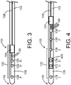
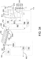
- FIG. 1 shows an exemplary distal portion of a device 100 of the present disclosure.
- device 100 comprises an elongated body 102, which can be a wire (insulated or non-insulated), a catheter, a hypotube, and/or another elongated body known or developed in the medical arts relating to and for use with blood vessel entry and navigation.
- a circuit module 104 (which may also be referred to herein as a control module), as shown in FIG. 1 , can be formed in, placed/positioned in, or placed/positioned on, part of device 100 (which may also be referred to herein as impedance devices given their impedance operation/functionality).
- elongated body 102 would connect to circuit module 104 so to permit signal data to travel from elongated body 102 to circuit module 104, and in some embodiments, to allow signal data to travel from circuit module 104 to elongated body 102.
- a conductive element 106 (such as a conductive wire, for example), can be present inside of, formed within, or positioned or coupled to an outside of, elongated body 102, and extend from circuit module 104 to a location proximal to circuit module, such as a data acquisition and processing system 250 (an exemplary console, as shown in FIG. 2 ).
- conductive element 106 may be formed as a coil, and use of a first conductor (such as elongated body 102) and a second conductor (such as conductive element) would allow for the transmission of power/current and the transmission of data in a bidirectional manner using only device 100.
- a distal section 108 of device 100 would extend from circuit module 104 to a distal end 110 of device 100, as shown in FIG. 1 .
- Distal section 108 in various embodiments, would include a sizing portion 120, comprising, for example, a plurality of electrodes (such as electrodes 122, 124, 126, 128 referenced in detail herein) used to obtain cross-sectional area, diameter, and/or other measurements of luminal organ geometry when device 100 is positioned within a luminal organ.
- Sizing portion 120 may include one or more electrodes, such as, for example, two detection electrodes (122, 124, also shown as "D" in FIG.
- sensors or electrodes such as a pressure sensor (an exemplary "other sensor 130” shown as “P”), and/or a temperature sensor (another exemplary "other sensor 130” shown as “T”), as shown in FIG. 1 , can also be positioned along or within device 100, such as at distal section 108 or another portion of device 100.
- Other types of sensors 130 can be used, such as, for example, pH sensors, flow sensors, velocity sensors, thermistors, and/or other types of chemical sensors, and be included with device 100 as referenced herein with respect to pressure and/or temperature sensors 100.
- less than two detection electrodes 122, 124 and/or less than two excitation electrodes 126, 128 may be used to obtain sizing data, such as by using two or three overall electrodes for sizing.
- Wires 150 can be used to individually connect the various electrodes and/or sensors to circuit module 104.
- one wire 150 can be used to connect excitation electrode 126 to circuit module 104, while another wire 150 can be used to connect detection electrode 122 to circuit module 104.
- one connection is used to connect excitation electrode 126 to excitation electrode 128 (using one wire 150) and to then connect excitation electrode 128 to circuit module 104 (using the same wire 150 or another wire 150 connected in series), so that circuit module 104 is connected to excitation electrode 126 and 128 from one wire 150 extending from circuit module 104.
- one connection is used to connect detection electrode 122 to detection electrode 124 (using one wire 150) and to then connect detection electrode 124 to circuit module 104 (using the same wire 150 or another wire 150 connected in series), so that circuit module 104 is connected to detection electrodes 122 and 124 from one wire 150 extending from circuit module 104.
- one connection is used to connect excitation electrodes 126, 128 and/or detection electrodes 122, 124, those pairs of electrodes would effectively act as a single electrode (as the two would be shorted together), and another electrode, such as a pad 200 (referenced in further detail below) would act as a return electrode.
- Excitation electrodes 126, 128 can, when in operation, excite an electric field within a mammalian luminal organ, which can be detected by detection electrodes 122, 124, so that conductance measurements can be obtained using impedance.
- At least one embodiment of a device 100 of the present disclosure would include a circuit module 104 and a distal section 108 distal to circuit module, and further comprise a sizing portion 120 and at least one additional sensor 130, such as, for example, a temperature sensor and/or a pressure sensor.
- a signal (through a circuit) can be transmitted either back through elongated body 102 or conductive element 106, or via a pad 200 positioned upon and/or generally external to the patient, so that signal data can extend from the electrodes and/or sensors, through the bloodstream, to pad 200, and ultimately to, for example, data acquisition and processing system 250, as shown in FIG. 2 .
- Pad 200 in such an embodiment, would be coupled to data acquisition and processing system 250 by way of a pad wire 202, for example, so that the overall signal circuit is complete.
- device 100 can couple directly to data acquisition and processing system 250, or can be connected to data acquisition and processing system 250 by way of an exemplary coupler 210, as shown in FIG. 2 .
- data relating to sizing can be obtained, along with additional data, such as relating to pressure or temperature, using the various electrodes and/or sensors referenced above. This can be accomplished using the circuit referenced above, for example, and can allow device 100 to be manufactured/configured using fewer components than would otherwise be required.
- a signal from device 100 can be detected using pad 200 and transmitted to data acquisition and processing system 250 without requiring some sort of return wire or conductor from device 100 to data acquisition and processing system 250.
- Power/current can be transmitted from data acquisition and processing system 250 to operate/activate circuit module 104, to provide current to excitation electrodes 126, 128 so that they can generate an electric field within a luminal organ detectable by one or more detection electrodes 122, 124, etc.
- Data can then be returned back to data acquisition and processing system 250 (such as sizing, pressure, temperature, etc., data), either via pad 200 or back through device 100, as provided in further detail below.
- device 100 is configured with electrodes used for sizing, such as one or more detection electrodes 122, 124 and one or more excitation electrodes 126, 128, and without any other electrodes or sensors.
- electrodes used for sizing such as one or more detection electrodes 122, 124 and one or more excitation electrodes 126, 128, and without any other electrodes or sensors.
- an exemplary device embodiment may comprise two detection electrodes 122, 124 positioned in between two excitation electrodes 126, 128, with wires 150 connecting the individual electrodes (or pairs of electrodes, as referenced above), to circuit module 104.
- elongated body 102 and/or conductive element 106 can be used as a return ground in addition to being used as a signal source (such as providing a signal and/or current from data acquisition and processing system 250, whereby the current is used to ultimately activate one or more excitation electrodes 126, 128, for example).
- the circuit could be completed using device 100 alone, such as by (a) a signal from data acquisition and processing system 250 through elongated body 102 to circuit module 104 and ultimately back through elongated body 102 to data acquisition and processing system 250, (b) a signal from data acquisition and processing system 250 through elongated body 102 to circuit module 104 and ultimately back through conductive element 106 to data acquisition and processing system 250, (c) a signal from data acquisition and processing system 250 through conductive element 106 to circuit module 104 and ultimately back through elongated body 102 to data acquisition and processing system 250, and/or (d) a signal from conductive element 106 through elongated body 102 to circuit module 104 and ultimately back through conductive element 106 to data acquisition and processing system 250.
- This bidirectional operation/functionality would utilize a circuit module 104 that, in various embodiments, can harvest power/current, facilitate the excitation of excitation electrodes 126, 128, have amplification capability, handle alternating and direct current, and/or transmit a signal back through elongated body 102, conductive element 106, and/or through the bloodstream to be detected by pad 200.
- conductive elements 106 to provide power to the various sensors/electrodes could be, for example, handled by (a) its use as a single conductor in device 100 and the second electrode (such as excitation electrodes 126, 128 connected to circuit module 104 ground) and connected through an electrode (pad 200, for example) on the body surface to connect back to data acquisition and processing system 250 to complete the circuit, or (b) using two conductors in the wire (two conductive elements 106 or one conductive element 106 plus a conductive elongated body 102) to connect power and ground.
- Circuit modules 104 of the present disclosure could, for example, be powered with 0-3V power, which could power conductance circuitry (within circuit modules 104 and/or in connection with excitation electrodes 126, 128) and send data/signal back to data acquisition and processing system 250, and if powered with -3-0V, other sensors/circuitry, such as pressure and/or temperature sensors (referred to herein as other sensors 130) can be powered and/or pressure and/or temperature data can be transmitted back from circuit modules 104.
- sensors/circuitry such as pressure and/or temperature sensors (referred to herein as other sensors 130) can be powered and/or pressure and/or temperature data can be transmitted back from circuit modules 104.
- the various operations/functionality could be facilitated by, for example, encoding which circuit to power and transmit using a control line (such as conductive element 106) or, for example, a higher voltage pulse on the power line (elongated body 102 and/or conductive element 106) to toggle between functions, or even by using different power voltages (such as 3V and 5V, for example).
- a control line such as conductive element 106
- a higher voltage pulse on the power line elongated body 102 and/or conductive element 106
- different power voltages such as 3V and 5V, for example.
- a direct current (DC) power signal can be sent along with data signals.
- more than one circuit module 104 may be used within a single device 100.
- excitation of excitation electrodes 126, 128 and conductance measurements may require two or more circuit modules 104, or using one circuit module 104 and a subset of features within another circuit module 104, to facilitate the same.
- all or a subset of the required/necessary functionality of an exemplary circuit module 104 could be implemented within a circuit module 104 as a means of reducing the required number of independent conductors integrated into the device 100 body.
- one or more of detection electrodes 122, 124 and/or excitation electrodes 126, 128 could be condensed into an additional circuit module 104 (an exemplary integrated circuit or micromachine assembly).
- circuit module 104 would itself operate as an electrode (such as one of the excitation electrodes 126, 128 or one of the detection electrodes 122, 124), thus reducing the overall need for one of the electrodes within sizing portion 120.
- an electrode such as one of the excitation electrodes 126, 128 or one of the detection electrodes 122, 124
- circuit module 104 could replace another electrode.
- At least one device 100 embodiment comprises a microassembly 400 having detection electrodes 122, 124 thereon/therein, or otherwise configured so that microassembly 400 and at least another electrode would operate as detection electrodes 122, 124.
- a microassembly 400 when used with exemplary device 100 embodiments of the present disclosure, would allow for more precision with respect to a length ("L") between detection electrodes 122, 124.
- microassemblies 400 and/or circuit modules 104 of the present disclosure are flexible or inherently flexible given their relative size/dimensions.
- G T CSA ⁇ ⁇ L + G p
- L a constant determined by the distance between detection electrodes 122, 124
- ⁇ the specific electrical conductivity of the local fluid (such as blood)
- G p the parallel conductance
- a precise L is important, and use of a microassembly 400 to specifically place electrodes 122, 124 thereon, for example, could be more accurate than otherwise placing separate electrodes along device 100. Such a microassembly 400 could also be positioned in various locations between excitation electrodes 126, 128. Various other microassembly 400 embodiments can have any number of electrodes/sensors of the present disclosure positioned thereon, as desired.
- exemplary devices 100 of the present disclosure could use power provided to circuit module 104 from data acquisition and processing system 250 and leverage the power to two electrodes/sensors.
- power from circuit module 104 to a pressure sensor 130 could be leverage to provide power to an excitation electrode 128, for example, through the same wire 150 or two wires 150 connected in series. Additional efficiencies could also be had to reduce the number of electrodes or components by way of sharing power via one wire 150 or two wires 150 connected to two electrodes and/or sensors in series, or using one component (such as circuit module 104) itself as an electrode.
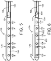
- FIG. 5 An additional embodiment of an exemplary device 100 of the present disclosure is shown in FIG. 5 .
- device 100 is similar to device 100 shown in FIG. 1 , but without wires 150 connecting circuit module 104 to the various electrodes/sensors shown therein.
- the various electrodes/sensors would operate via a wireless connection (via wireless communication) with circuit module 104, which is powered, for example, using conductive element 106 or another power source in various embodiments.
- device 100 as shown in FIG. 5 , would be operable so that the various electrodes/sensors would be able to obtain information/data, as referenced herein, and circuit module 104 could obtain/access said information/data, wirelessly.
- FIG. 6 shows an additional embodiment, similar to FIGS.
- a microassembly 400 having electrodes/sensors thereon is also in wireless communication with circuit module 104.
- Various electrodes/sensors can be positioned on, etched along, or embedded within, exemplary microassemblies 400 and/or circuit modules 104 of the present disclosure.
- Said wireless communication in various embodiments, can be unilateral (such as from electrodes/sensors to circuit module 104, or vice versa), or bilateral (such as between electrodes/sensors and circuit module 104).
- circuit module 104 (or other portions of an exemplary device 100 of the present disclosure) may comprise (be configured to have), or have in addition thereto, a wireless communication module 600 configured to communicate with various electrodes/sensors of the present disclosure.
- Wireless communication module 600 in various embodiments, can also be powered using conductive element 106 or another power source.
- FIG. 6 also shows a balloon 602 positioned around at least part of device 100, so that balloon 602 can be inflated and/or deflated as desired, such as within a luminal organ, to allow for conductance and/or other measurements to be obtained within balloon 602 using impedance, as generally referenced herein.
- Such an embodiment would allow, for example, sizing data (cross-sectional area, for example, using the conductance measurements), pressure data, etc., within balloon 602 at various degrees of inflation.
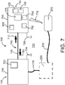
- FIG. 7 shows another exemplary system 300 of the present disclosure.
- an exemplary system 300 may comprise a device 100, which itself comprises a proximal electrical unit 700, a guide wire 740 (comprising at least one conductive element 106 therethrough (also referred to as a conductor), and sensor substrate 760 which may comprise an exemplary elongated body 102 of the present disclosure), and a sensor substrate 760 at or near a relative distal end 110 of the device 100, with said system 300 comprising one additional element, such as a pad 200 (also referred to herein as a patch electrode) and/or a data acquisition and processing system 250, for example.
- a pad 200 also referred to herein as a patch electrode
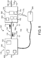
- FIG. 8 shows another exemplary system 300 embodiment, whereby device 100 has a first part of guide wire 740 between proximal electrical unit 700 and sensor substrate 760, and a second part of guide wire 740 distal to sensor substrate 760, whereby the second part of guide wire 740 has a sizing portion 120 and/or one or more other sensors 130 positioned thereon and/or embedded therein, such as a pressure sensor 130.
- proximal electrical unit 700 can process data signals 765 (referenced in further detail herein) returning from sensor substrate 760 and generally govern operation of proximal electrical unit 700 using one or more components therein and/or coupled thereto, such as, for example, a microprocessor 900 referenced below in connection with FIG. 9 . It is to be understood that the data signal 765 travels from the distal portion (sensor substrate 760) to proximal unit 700. It is further to be understood that the power signal 710 travels from the proximal unit 700 to sensor substrate 760.
- the carrier wave 1000 which uses the complete electrical circuit consisting of guide wire 106, distal unit 760, distal ground 768 (or another portion of or coupled to sensor substrate 760, as referenced in further detail herein), tissue 730, pad 200, wire 202 and the proximal unit 700.
- Exemplary proximal electrical units 700 of the present disclosure comprise/include at least one power source 702, which may be referred to herein as a power generator and/or a power supply.
- Power source 702 may comprise its own direct source of power, such as a battery embodiment of a power source 702, and/or may itself receive power from a universal serial bus (USB) or other connector 802 (as shown in FIG. 9 , for example), and/or another power cable supply 804, such as a traditional electrical cord configured to be plugged into a traditional power outlet with an appropriate power regulator.
- USB universal serial bus
- Power from power source 702, USB connector 802, and/or power cable supply 804 can be provided directly to conductor 106 and/or indirectly to conductor 106 through one of the aforementioned sources/connectors/supplies and/or one or more other components of proximal electrical unit 700.
- Power delivered to conductor 106 from proximal electrical unit 700 travels through conductor 106 to one or more elements/components within, upon, and/or embedded within sensor substrate 760. As shown in FIG. 7 , for example, power 710 is represented by the bold arrow pointing to the right.
- power 710 is delivered from power source 702, USB connector 802, and/or power cable supply 804 as an alternating current (AC) or an oscillating direct current (DC), such as, for example, a carrier wave traveling from the proximal unit 700 to distal unit (sensor substrate 760) in the form of an alternating current at 200KHz (alternating at 200,000 times per second).
- AC alternating current
- DC oscillating direct current
- Sensor substrate 760 may comprise a relatively small and/or thin substrate, whereby circuit module 104 (also referred to as an integrated circuit) is positioned thereon and/or embedded therein.
- Sensor substrate 760 may itself be a microassembly 400 of the present disclosure, or may be separate from microassembly 400.
- sensor substrate 760 may comprise or include circuit module 104, and microassembly 400 may comprise or include one or more of a sizing portion 120 and/or one or more other sensors 130 thereon and/or therein. As shown in FIGS.
- memory 764 (an exemplary storage medium of the present disclosure that can be connected to circuit module 104 and/or other components of sensor substrate 760, whereby memory 964 can store data 765 (as referenced herein) until it can be transmitted to the proximal electrical unit 700, for example.
- memory 764 can store various data as noted above, can include instructions and/or software therein to regulate/control various aspects of sensor substrate 700, such as provided in further detail herein.
- Elements/components of sensor substrate 760 can be powered using power 710 from conductor 106 to achieve several results.
- One result for example, can be to charge a capacitor 762 and/or provide power to a distal power source 766 (shown in FIG. 8 ) within or upon sensor substrate 760, so that power from capacitor 762 and/or distal power source 766 can be used to operate one or more elements within or coupled to sensor substrate 760.
- Another result can be to directly cause one or more of sizing portion 120 and/or other sensors 130 to operate (namely those requiring power to operate), such as to generate an electric field using excitation electrodes 122, 124 of sizing portion 120 (or to generate an electric field using other elements of sizing portion 120), for example.
- Yet another result can be to transmit a data signal 765 from one or more of sizing portion 120 and/or other sensors 130 back to proximal electrical unit 700 via one or more conductive elements 106 and/or wirelessly as noted below.
- data signal 765 is represented by the bold arrow pointing to the left.
- data may be transmitted back to proximal electrical unit 700 via or more pads positioned upon the patient, such as, for example, using a wired or wireless communication module 600 (an exemplary transmitter configured to transmit data to proximal electrical unit 700, for example) within or coupled to sensor substrate 760 to transmit a data signal 765 to proximal electrical unit 700.
- a wired or wireless communication module 600 an exemplary transmitter configured to transmit data to proximal electrical unit 700, for example
- a distal power source 766 may be used in connection with capacitor 762 such that distal power source 766 can provide the necessary power to effectuate one or more of the foregoing, and in various embodiments, can also convert alternating current (such as provided by power source 702) to direct current so to operate one or more components of sensor substrate 760.
- alternating current such as provided by power source 702
- power from conductor 106, capacitor 762, and/or distal power source 766 can be used to effectuate/facilitate one or more of the foregoing results.
- Capacitors 762 in various embodiments, can be used by distal power source 766 to power various circuitry within sensor substrate 760, especially in situations where power 710 from guide wire 740 may be inconsistent and therefore somewhat unreliable, whereby capacitor 762 and distal power source 766 work in connection with one another to deliver consistent and reliable power 710 to portions of sensor substrate 760.
- Data signal 765 originates from componentry upon, within, and/or connected to sensor substrate 760 as shown in FIGS. 7 or 8 .
- Data signals 765 can include pressure, temperature, and/or impedance data, and are transmitted back to proximal electrical unit 700 via guide wire 740, in various embodiments.
- FIGS. 7 and 8 General circuits are also shown in FIGS. 7 and 8 .
- power 710 generally travels from proximal electrical unit 700 through guide wire 740 and to componentry within, upon, and/or connected to sensor substrate 760.
- the power circuit is then completed through the body (such as indicated using ground 768 and/or signal 770, in various embodiments) to a pad 200 placed upon the body, which is then wired back to proximal electrical unit either directly, such as shown in FIG. 8 , or indirectly, such as shown in FIG. 7 .
- Data signals 765 can flow in one form or another (also as described in further detail herein) from componentry of and/or coupled to sensor substrate 760, through or along guide wire 740 to proximal electrical unit 700.
- the data signal 765 circuit is then completed through the body via pad 200 via tissue 730, as shown in FIGS. 7 and 8 .
- elongated body 102 can be anywhere between 0.010" and 0.050" in diameter, such as between 0.010" and 0.030" in diameter, including, but not limited to, diameters of 0.014" and 0.035".
- Guide wires 740 can be constructed using various metallic and polymeric materials, and can use one or more conductors 106 as referenced herein.
- Sensor substrate 760 and/or various sizing portion 120 components and/or sensors 130, would be at or close to such an overall diameter/size so to allow devices 100 and/or parts of systems 300 of the present disclosure to navigate within a vasculature and obtain data as generally referenced herein.
- proximal electrical unit 700 power is transmitted from proximal electrical unit 700 through conductor 106 and into tissue 730 (such as via proximal ground 704, for example), to operate portions of system 300 to obtain data that is then transmitted from sensor substrate 760 to proximal electrical unit 700, so that proximal electrical unit 700 obtains feedback (in the form of data) from sensor substrate 760.
- Exemplary systems 300 of the present disclosure may also have additional componentry such as shown in FIG. 9 .
- one or more exemplary systems 300 of the present disclosure may comprise a device 100 comprising a proximal electrical unit 700, a guide wire 740, and a sensor substrate 760.
- Proximal electrical unit 700 as described herein in various embodiments, may comprise/be a handle or other configuration and include a power source 702 and optionally may include a USB or other connector 802 and/or a power cable supply 804 (as shown in FIG. 8 ).
- USB or other connector 802 can be used as a source of power, as previously described herein, and/or used to transmit data (such as data signal 765) outside of proximal electrical unit 700, such as via wired or wireless connection to a computer (not shown) connected to proximal electrical unit 700.
- a microprocessor 900, or functionally-equivalent componentry may be present within or as part of proximal electrical unit 700, configured for several different types of operation, such as, for example, controlling power 710 and/or data signal 765 flow through portions of proximal electrical unit 700, accessing optional memory 902 (an exemplary storage medium of the present disclosure) in communication with microprocessor 900 so to control one or more aspects of device 100 such as the foregoing, and the like.
- FIG. 9 also shows a receiver 904, in communication with guide wire 740, which operates to receive one or more data signals 765 from guide wire 740, whereby said one or more data signals 765 can be provided/displayed to a user of device 100, accessed by microprocessor 900 to control future power 710, to store said one or more data signals 765 within memory 902, and/or to compare the one or more data signals 765 to each other, to other data signals 765 within memory 902, and/or to other data stored within memory 902, such as calibration information/data in connection with various sensor(s) 130 and/or sizing portion(s) 120.
- a receiver 904 in communication with guide wire 740, which operates to receive one or more data signals 765 from guide wire 740, whereby said one or more data signals 765 can be provided/displayed to a user of device 100, accessed by microprocessor 900 to control future power 710, to store said one or more data signals 765 within memory 902, and/or to compare the one or more data signals 765 to
- Data signals 765 and/or other data can be stored within memory 902 and outside of proximal electrical unit 700 so that if some or all of a connection to proximal electrical unit 700 is lost during operation, such as via USB or other connector 802, device 100 can still operate using data within memory 902 accessible using microprocessor 900.
- Memory 902 in various embodiments, can store various data as noted above, can include instructions and/or software therein to regulate/control various aspects of proximal electrical unit 700, interface with a data acquisition and processing system 250, etc.
- Proximal electrical units 700 can form and/or be located in a relative handle portion of device 100, as referenced above, which can be held by a medical professional using said device 100.
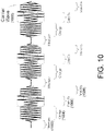
- proximal electrical units 700 of the present disclosure can generate a carrier wave 1000, referenced herein in further detail and shown in FIG. 10 , for example), that can be sent to sensor substrate 760 over the circuit formed by guide wire 740 and tissue 130.
- Exemplary carrier waves 1000 can provide power 710 necessary to operate elements within sensor substrate 760, and can be modulated by sensor substrate 760 to send data signals 765, which are recovered by proximal electrical unit 700 by the demodulation of the carrier wave 1000.
- Carrier waves 1000 can also be interrupted, as referenced in further detail herein, to indicate to the sensor substrate 760 that it is safe to obtain measurements.
- Proximal electrical units 700 of the present disclosure can also relay data signals 765 obtained from sensor substrate 760 to a data acquisition and processing system 250, such as shown in FIG. 7 , for further processing and/or display purposes, which can be facilitated using USB, RS-232, Wi-Fi, Bluetooth, Zigby, and/or other known or developed wired and/or wireless means of transmitting data.
- data signals 765 are modulated when sent from the distal part of device (sensor substrate 760) through guide wire 740 to proximal electrical unit 700.
- receiver 904 is configured to demodulate said data signals 765 so that the demodulated data signals 765 can be acted upon (received, processed, etc.) by microprocessor 900.
- an exemplary sensor substrate 760 of the present disclosure may comprise a circuit module 104 (also referred to herein as an integrated circuit), a wired or wireless communication module 600 (an exemplary transmitter, configured to transmit data signals 765 from sensor substrate 760 to guide wire 740 so that data signals 765 can be provided to proximal electrical unit 700), a pressure sensor (an exemplary sensor 130), and a sizing portion 120 (comprising electrodes 122, 124, 126, 128, for example).
- a circuit module 104 also referred to herein as an integrated circuit
- a wired or wireless communication module 600 an exemplary transmitter, configured to transmit data signals 765 from sensor substrate 760 to guide wire 740 so that data signals 765 can be provided to proximal electrical unit 700
- a pressure sensor an exemplary sensor 130
- a sizing portion 120 comprising electrodes 122, 124, 126, 128, for example.
- wires or traces 980 may be present within proximal electrical unit 700 and/or sensor substrate 760, used to connect any number of components to one another for operation as generally referenced herein. Exemplary wires or traces 980 are shown in FIG. 9 .
- An exemplary pressure sensor (sensor 130) of the present disclosure may have a diaphragm 910 that bends in response to changes in pressure thereto.
- the three left pointing arrows in FIG. 9 are indicative of a force against diaphragm 910 of sensor 130 whereby, for example, an outer portion of diaphragm 910 is elongated and an inner side of diaphragm 910 is compressed.
- An exemplary bridge 912 connected to sensor 910 directly or via one or more wires or traces 980, can measure extremely small differences between the inner and outer sides of diaphragm 910 (thereby detecting very small signals from sensor 130), and via one or more amplifiers 914 connected thereto, can share one or more data signals 765 from sensor 130 to multiplexer 920 and/or directly to a transmitter (wired or wireless communication module 600), which can then send data signals 765 to proximal electrical unit 700 through guide wire 740 and/or wirelessly (such as by using one or more wireless signals, radio frequency signals/waves, Bluetooth, etc.) when a wireless transmitter is used.
- Amplifiers 914 as shown in FIG.
- bridge 912 can amplify data signals 765 from bridge 912 so to increase the overall strength of data signals 765.
- bridge 912 can actually receive two pieces of data from the pressure sensor (sensor 130), with one being a difference between the inner and outer diaphragm 910 changes, relating solely to a change in pressure, and the other being a sum of said changes, which utilizes a temperature component as well (as a pressure sensor 130, for example, can compensate for temperature changes).
- amplifiers 914 can amplify both types of data signals 765 (pressure, indicated as "P” in FIG. 9 , and temperature, indicated as "T” in FIG. 9 ).
- an amplifier can amplify impedance (indicated as "Z" in FIG. 9 ) data signals 765 from sizing portion 120, as shown in FIG. 9 , so to increase their overall strength prior to getting to a multiplexer 920.
- Exemplary pressure sensor(s) 130 of the present disclosure can be placed near the distal tip/end 110 of the medical device 100 and is/are designed to measure the pressure of the blood.
- at least one embodiment consists of a pair of strain gauges mounted on the opposite sides of a flexible substrate (the diaphragm 910 mentioned above), which bends and changes it curvature when the force applied on one side changes relative to the opposing side.
- the two aforementioned strain-gauges are configured as a differential pair, the signal that is measured from a full or half Wheatstone bridge is proportional to the normal force that is applied on the pressure sensor 130.
- the strain gauges are configured as resistors in series, then the signal that is produced is proportional to the temperature of the blood, as generally referenced above.
- a multiplexer 920 can obtain data signals 765 from various inputs, such as sensor(s) 130 and/or sizing portion 120, and forward and/or process one data signal 765 at a time, as desired.
- multiplexer 920 as shown in the figure, can obtain pressure and temperature data signals 765 from sensor 130 (configured as a pressure sensor), as well as sizing (impedance) data signals 765 from sizing portion 120.
- Multiplexer 920 after receiving said data signals 765, can share them one at a time, such as, for example, first sharing a data signal 765 from or relating to sizing portion 120, and then sharing a data signal 765 from or relating to sensor 130.
- An analog-to-digital converter 922 can be connected to (in communication with) multiplexer 920, and operate to convert analog data signals 765 from sizing portion 120 and/or sensor(s) 130 to digital signals 765, which are then forwarded to circuit module 104 (such as an integrated circuit and/or microprocessor) and transmitted back to proximal electrical unit 700 via wired or wireless communication module 600 (an exemplary transmitter of the present disclosure).
- wired or wireless communication module 600 is itself an electrode (or configured as an electrode), such as a coil, one of electrodes 122, 124, 126, or 128, or a separate electrode, so that data signals 765 can properly be transmitted back to proximal electrical unit 700.
- Exemplary sensor substrates 760 may utilize one or more switches during operation.
- a first switch 930 may be used to electrically connect (via power 710 and/or data signal(s) 765) guide wire 740, wired or wireless communication module 600, and distal power source 766.
- a second switch 932 may be used to electrically connect (via power 710 and/or data signal(s) 765) distal power source 766 with tissue 730, as shown in FIG. 9 .
- FIG. 13 shows the event generation 1300 that is governed by the distal unit (sensor substrate 760), which runs as a slave to the proximal electrical unit 700. Briefly, and as shown in FIG.
- event generation 1300 is started at start step 1302, and sensor substrate 760 is initially effectively connected to guide wire 740 and tissue 130, by being in the ISOLATE OFF state (at isolate off state 1304), which is achieved by the closure of the switches S1 (first switch 930) and S2 (second switch 932), as shown in FIG. 9 .
- the capacitors 762 referenced herein are charged to provide the power that will be necessary to operate the distal circuitry (within sensor substrate 760) when the carrier wave 1000 will be interrupted.
- Distal unit continues to monitor the power (via is power on step 1306), and when the power is off, that is when the carrier wave 1000 is interrupted by proximal electrical unit 700, sensor substrate 760 enters into the measurement mode (measurement step 1310).
- First the distal tip electronics (components within sensor substrate 760) are isolated from the tissue 130, as indicated by the ISOLATE ON state in FIG. 9 (isolate on state 1308), which is achieved by the opening of the switches S1 and S2 (first switch 930 and second switch 932, respectively), as shown in FIG. 9 .
- impedance, pressure and/or temperature measurements can be made, and the electrical isolation of the distal tip electronics is terminated (via isolate off state 1312).
- the distal tip circuitry (of sensor substrate 760) waits for the restoration of the carrier wave by the proximal circuitry (of proximal electrical unit 700) before attempting to send the resulting measurements (data signals 765) back to proximal electrical unit 700 (via data transmission step 1318), which is done by the modulation of the carrier wave 1000.
- a brief delay (delay state 1316) can precede data transmission step 1318.
- Modulation scheme can be chosen among many that are available, such as amplitude modulation, pulse position modulation, pulse width modulation, and so on.
- coding of the data (data signal 765) can be done by choosing from a large selection of techniques that are available.
- Amplitude modulation and Manchester Coding may be preferred as they do generate signals with zero offset, which is important for data signals 765 sent over tissue 130 to prevent adverse effects and unintentional stimulation. Opening and closing of switches 930, 932 are discussed in further detail herein.
- proximal electrical unit 700 and/or sensor substrate 760 may be present within proximal electrical unit 700 and/or sensor substrate 760, used to connect any number of components to one another for operation as generally referenced herein. Exemplary wires or traces 980 are shown in FIG. 9 .
- Novel operation of exemplary devices 100 and/or systems 300 of the present disclosure can be described in view of the exemplary carrier wave timing diagram shown in FIG. 10 .
- a single carrier wave 1000 is used along with the overall power signal from the proximal electrical unit to direct operation of various aspects of device 100 and/or systems 300.
- an exemplary carrier wave 1000 has a measurement portion 1002, whereby measurements using device 100 are obtained within a mammalian vasculature, and a charge portion 1004, whereby elements within sensor substrate 760 are charged using power 710 from conductor 106 (or, phrased differently, whereby power 710 is turned back on by the proximal electrical unit 700).
- Carrier waves 1000 of the present disclosure also include a data transmission portion 1006, whereby data obtained using device 100 is transmitted back to proximal electrical unit 700, and a stand-by portion 1008, where no data is obtained or transmitted, and which acts as a trigger for device 100 and/or system 300 to obtain additional data.
- power 710 is not provided from the proximal electrical unit 700 to the sensor substrate 760, which can act as a trigger for one or more components of sensor substrate 760 to obtain one or more pressure, temperature, and/or impedance measurements.
- components of the sensor substrate 760 may vary the overall amount of current/power it is draining, and proximal electrical unit 700 can monitor said power drain.
- Sensor substrate 760 can intentionally alter an amount of power it is draining (such as relatively less power or relatively more power, considered as a binary 0 or 1).
- power 710 can be used to charge capacitor 762 as well, in various embodiments.
- exemplary devices 100 of the present disclosure are operable and/or configured to send power 710 and multiple data signals 765 over the same guide wire 740.
- Sizing portion 120 and/or sensor(s) 130 of the present application interface electrically, as various devices 100 and send current (power 710) and obtain various measurements (resulting in data signals 765) at the same time or very close in time to one another.
- power 710 and data signals 765 can be sent over the same core, with the overall power and data circuits completed by the body (tissue 130).
- devices 100 of the present disclosure can be consider as using multiple channels, in various embodiments, of data signals 765 and power 710.
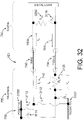
- FIG. 11 shows steps of an exemplary event generation 1100 from an exemplary proximal electrical unit 700 of the present disclosure.
- an exemplary device 100 can start operation (using start step 1102) and power transmission can be turned off (using power off step 1104), whereby measurements can be obtained using portions of device 100 and/or system 300, such as impedance, pressure, and/or temperature measurements, either at power off step 1104 or delay step 1106, which is included so to allow time for inherent tissue capacitance to go down to allow for cleaner measurements. Said measurements would be obtained when no power is being transmitted through conductor 106 to sensor substrate 760, for example, so to minimize the potential negative feedback from such a transmission during data acquisition, allowing for a cleaner (and therefore more accurate) data acquisition process.
- Power can then be turned on (using power on step 1108) to provide power to sensor substrate 706 so that, for example, wireless communication module 600 within sensor substrate 760 can send the data signal 765 to proximal electrical unit 700, for example.
- Another delay step 1110 follows the power on step 1108, so that tissue capacitance due to power on step 1108 can be reduced and allow for a cleaner transmission of data acquired using device 100 and/or system 300 within data receipt step 1112.
- An additional delay step 1114 may follow data receipt step 1112, with the final step in the event generation 1100 shown in FIG. 11 being to send the data signal 765 to either the proximal electrical unit 700 and/or to a data acquisition and processing system 250 at data transmission step 1116.
- delay steps 1106, 1110, and 1114 are optional, but are recommended in various embodiments so to allow for the cleanest operation of device 100 and/or system 300.
- Device 100 and/or system 300 embodiments using a single conductor can use mammalian tissue 130 to complete the overall power and/or data circuits.
- Said devices 100 would have preferred flexibility and/or steerability, as guide wires 740 of such a small size as referenced herein would be somewhat compromised should more than one core (conductive element 106) be used.
- the present disclosure does also include disclosure of devices 100 having two or more cores (conductors / conductive elements 106), such as shown in FIG. 12 , so that the overall circuit can be completed within device 100. For example, and as shown in FIG.
- device 100 can comprise a proximal electrical unit 700, a guide wire 740 having two conductive elements 106, and a distal sensor substrate 760, each having various features and/or elements as referenced herein.
- Power 710 and data signals 765 can be transmitted over/through the loop created by proximal electrical unit 700, a first conductive element 106, sensor substrate 760, and a second conductive element 106, as shown in FIG. 12 .
- At least one issue that must be addressed by the distal circuitry is the existence of a common electrical path between the power circuitry and impedance that is being measured, for example.
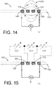
- the principles of electrical impedance measurements using the quadripolar (tetrapolar) impedance technique are illustrated in FIGS. 14 and 15 .
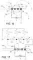
- FIGS. 16 and 17 As identified within FIGS. 16 and 17 , when the power is supplied over the same tissue that the impedance is measured from, a residual shunt path remains in the measurement path, making the results of the impedance measurement inaccurate.
- electrodes 122, 124, 126, 128 are formed as rings around the distal portion 110 of device 100. These electrodes are usually 1 mm wide bands and are constructed from a platinum-iridium alloy, but different sizing and different materials are included within the present disclosure. Spacing between the individual electrodes 122, 124, 126, 128 is in the range of 0.5 to 10 mm.
- FIG. 18 shows a distal portion (sensor substrate 760) of an exemplary device 100 of the present disclosure, having two capacitors 762, four electrodes 122, 124, 126, 128, a pressure sensor (exemplary sensor 130), and an integrated circuit (circuit module 104), connected as shown using various wires or traces 980, configured for operation as generally referenced herein.
- FIG. 18 shows a distal portion (sensor substrate 760) of an exemplary device 100 of the present disclosure, having two capacitors 762, four electrodes 122, 124, 126, 128, a pressure sensor (exemplary sensor 130), and an integrated circuit (circuit module 104), connected as shown using various wires or traces 980, configured for operation as generally referenced herein.
- FIG. 18 shows a distal portion (sensor substrate 760) of an exemplary device 100 of the present disclosure, having two capacitors 762, four electrodes 122, 124, 126, 128, a pressure sensor (exemplary sensor 130), and an integrated circuit (circuit module 104), connected as shown
- FIGS. 19 shows exemplary power 710 and data signal 765 flow directions using various devices 100 of the present disclosure, whereby, for example, power 710 flows from proximal electrical unit 700 through guide wire 740 to sensor substrate 760, to pad 200 (via one or more mechanisms or methods noted above, such as by contact of a metallic component of or coupled to sensor substrate 760 so to continue the general circuit/loop) and back to proximal electrical unit 700 via pad wire 202 and/or coupler 210, and whereby, for example, data signals 765 flow from sensor substrate 760 through guide wire 740 to proximal electrical unit 700 and back to sensor substrate 760 as shown therein to complete the loop/circuit. As shown in FIGS.
- power 710 is shown as generally moving in one direction and data signals 765 are generally shown as moving in another direction.
- electrons from oscillating alternating current (AC) or pulse direct current (DC), as desired
- AC alternating current
- DC pulse direct current
- FIGS. 7 , 8 , and 19 are included to depict, for example, the overall flow of power 710 from power source 702 to circuit module 104 of sensor substrate 760, for example, and the overall flow of data signals 765 from circuit module 104 back to proximal electrical unit 700.
- the overall circuit is completed using two conductors, at least one being one or a first conductive element 106 of guide wire 740, and the other being completed through the body back to pad 202 and pad wire 202, for example, as referenced herein.
- various devices 100 and systems 300 of the present disclosure are useful to obtain measurements within a mammalian vasculature, such as to identify locations of stenotic regions, for example, and to obtain cross-sectional area measurements using impedance to potentially aid in the pre-selection of various therapeutic devices.
- Impedance, blood pressure, and/or temperature can be obtained using various transvascular devices 100 and/or systems 300 of the present disclosure.
- various devices 100 of the present disclosure may comprise a sizing portion 120 having various electrodes, such as electrodes 122, 124, 126, and/or 128 referenced herein, including those four electrodes, additional electrodes, and fewer electrodes.
- Device 100 embodiments may comprise one or more of a sizing portion 120, a sensor 130 configured to obtain temperature measurements (such as a thermistor or thermocouple), and/or a sensor 130 configured to obtain pressure measurements (such as a pressure sensor).
- Other sensors 130 used in the medical arts may be incorporated into various device 100 and/or system 300 embodiments, as applicable.
- proximal circuitry Two custom circuits were built to test an exemplary embodiment of the present disclosure.
- One of the circuits is referred to as the proximal circuitry and performs the functions of a proximal electrical unit 700 such as shown in FIG. 7 including the generation of the carrier wave, transmission of the power, reception of the data from the distal circuitry and communication with an external computer.
- the operations of proximal electrical unit 700 in this example are governed by an chicken Uno micro-controller board running a program that was written in Processing Language. This same board did communicate with an external computer using a USB connection 802. Power was obtained from a 9 Volt primary battery. The overall current draw from the battery was approximately 80 milli-Amperes.
- the second circuitry is referred to as the distal circuitry and performs the functions of the elements within or upon sensor substrate 760 as shown in FIG. 7 , for example, including the power recovery from the carrier wave, the data transmission by the amplitude modulation (AM) of the carrier wave using the Manchester coding, data collection using the on board sensors including the pressure sensor, temperature sensor (both exemplary sensors 130) and the quadripolar/tetrapolar impedance sensor (an exemplary sizing portion 120).
- the pressure that was used is a differential strain gauge sensor which also served as temperature sensor.
- the operation of the distal circuitry was governed by a PIC 16F690 microcontroller running a program that was written in the language C++.
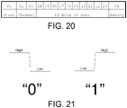
- the carrier wave that is used was a 200 KHz square wave that was generated by the proximal circuitry. Data transmission was done at 9,600 baud (bits per second) using data packages that are 14 bits long, which is described below and also illustrated in FIG. 20 :
- Use of Manchester code required the data transmission to be done using a logic level sequence of a low level followed by a high level for the transmission of a data value of "1” and a logic level sequence of a high level followed by a low level for the transmission of a data value of "0", as illustrated in FIG. 21 .
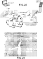
- the electrical circuit that is necessary to carry the wave was formed using a solid wire and the tissue as shown in FIG. 22 . Connections to the tissue were made using a pair of patch electrodes.
- a male rabbit was kept anesthetized using inhaled gas throughout the procedure.
- Vascular access was gained to the jugular and femoral veins via routine cut-down and with the placement of introducers at both sites.
- a 0.035" LumenRECON guide-wire was placed into the vein from the jugular entry point, and it was advanced into the superior vena cava.
- Radio-opaque dye that was introduced into the venous system was used to capture a venogram of the vessel which was later used to estimate the diameter of the vein at various locations while the guide-wire was being repositioned at four different positions.
- a 4 French Merit KA2 catheter was used to release room temperature normal saline (0.9% NaCl) from a distance of 19 mm from the center of the impedance electrodes numbered 2 and 3 (exemplary detection electrodes 122, 124 of an exemplary sizing portion 120).
- Quadripolar impedance data collected during the in vivo study Diameter (mm) Cross Sectional Area (mm 2 ) (V 2 -V 3 ) x 5 (volts) Conductance ( ⁇ -Siemens) 6.56 33.8 3.66 683.06 9.98 78.23 3.38 739.64 10.61 88.41 3.19 783.70 11.1 96.77 3.05 819.67
- Data shown in tabular format in Table 1 and in graphical format in FIG. 24 show the predicted relationship between the conductance and the cross sectional area of the blood vessel.
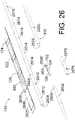
- conductive element has at least three segments, namely a proximal segment 2600, a distal segment 2602, and an inner segment 2604, whereby the proximal segment 2600 and the distal segment 2602 are each configured to couple to opposite ends of inner segment 2604.
- Inner segment 2604 is configured to receive a corresponding wrap 2650 thereon, wherein wrap 2650 is configured to be wrapped around most or all of inner segment 2604.
- Proximal segment 2600 can be connected/coupled to inner segment 2604, and distal segment 2602 can also be connected/coupled to inner segment 2604, using various connections and/or means, such as, for example, using one or more of an adhesive, weld (such as solder and/or using additional metal), melt (such as melting plastic), twisting, friction, etc.
- proximal segment 2600 and distal segment 2602 each have a tab 2606 at their end that will connect/couple to inner segment 2604, and inner segment 2604 has a pocket 2608 defined therein at each end to receive tabs 2606 to connect the same.
- a component housing 2675 is configured to receive various components of exemplary devices 100 of the present disclosure, such as a pressure sensor (an exemplary sensor 130), a circuit module 104 (also referred to herein as an integrated circuit or ASIC), and a capacitor 762.
- a transfer circuit 2680 can comprise various wires or traces 980 that are configured to touch or engage other wires or traces 980 formed on other parts of device 100, such as on or included within wrap 2650 and/or inner segment 2604.
- various wires or traces 980 can be used to connect one or more components within component housing 2675 and/or be used to provide the connections of transfer circuit 2680 so to allow the components within component housing 2675 to electrically communicate with other portions of device 100, such as, for example, other wires or traces 980, components of a sizing portion 120, a pressure sensor (exemplary sensor 130), conductive element (or conductor) 104, and the various parts thereof, such as proximal segment 2600 and/or distal segment 2602.
- components intended to be positioned within component housing 2675 such as the pressure sensor (sensor 130), circuit module 104, and capacitor 762, are positioned within component housing 2675.
- One or more component housing apertures 2676 is/are defined within component housing 2675 so to allow blood, for example, to contact pressure sensor (sensor 130) to permit pressure readings when device 100 is in use to obtain the same.
- Transfer circuit 2680 can either contact other wires or traces 980 of component housing 2675 that are configured to contact other wires or traces 980 or components of device 100, or transfer circuit 2680 can be exposed through a transfer circuit aperture 2678, as shown in FIGS. 30A and 30C , defined within component housing 2675 so to expose the same.
- Component housing 2675 can be positioned within inner segment 2604, so that one or more inner segment apertures 2610 defined within inner segment can correspond/align with one or more component housing apertures 2676 defined within component housing 2675.
- Wrap 2650 can be wrapped around inner segment 2604, and proximal segment 2600 and distal segment 2602 can be connected to inner segment 2604 to complete construction of the device 100 as shown in FIG. 26 .
- Wrap apertures 2655 as shown in FIG. 26 , can correspond/align with the one or more inner segment apertures 2610 and the one or more component housing apertures 2676.
- wrap 2650 when wrap 2650 is positioned around inner segment 2604, various components thereof (such as electrodes 122, 124, 126, 128 (shown in FIGS. 26 and/or FIG. 28C ), a distal conductor pad 2620, a proximal conductor pad 2700 (as shown in FIGS. 29D and 29E ), and/or various wires or traces 980) can contact various portions of inner segment 2604, such as wires or traces 980, distal conductor contact 2612, one or more electrode contacts 2614, and/or a proximal conductor contact 2616.
- various components thereof such as electrodes 122, 124, 126, 128 (shown in FIGS. 26 and/or FIG. 28C ), a distal conductor pad 2620, a proximal conductor pad 2700 (as shown in FIGS. 29D and 29E ), and/or various wires or traces 980
- wires or traces 980 can contact various portions of inner segment 2604,
- FIG. 27 shows a perspective view of a portion of the device 100 shown in FIG. 27 that is generally assembled but for positioning of the wrap 2650 around inner portion 2604.
- a pressure sensor (sensor 130), circuit module 140, and capacitor 762 are positioned inside device 100, with a partial cut-away view provided in FIG. 27 to see said components therein.
- FIG. 27 also shows a distal portion of a catheter 2750 configured for delivery over device 100 within a mammalian vasculature, whereby an optional fluid, such as saline, can be delivered therethrough so that a bolus of the fluid can pass over one or more sizing portions 120 and/or sensors 130 and be detected thereby, as generally referenced herein.
- an optional fluid such as saline
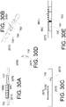
- FIG. 28A shows a cross-sectional view of a portion of an exemplary device 100 of the present disclosure as shown along cross-section B-B in FIG. 28C .
- device 100 with wrap 2650 positioned thereon, includes a pressure sensor (sensor 130) within a component housing 2675 having one or more component housing apertures 2676 defined therein, and a transfer circuit 2680.
- FIG. 28B shows a cross-sectional view along cross section A-B shown in FIG. 28D , whereby various components are shown inside of device 100 with wrap 2650 positioned thereon.
- 28C and 28D show side views, rotated 90° from one another, of distal portions of an exemplary device 100 of the present disclosure with a wrap 2650 positioned thereon, whereby electrodes 122, 124, 126, 128 and distal conductor pad 2620 are shown thereon.
- FIG. 29A shows a perspective view of a portion of an exemplary device 100 fo the present disclosure having a wrap 2650 positioned thereon, whereby electrodes 122, 124, 126, 128, distal conductor pad 2620, and proximal conductor pad 2700 are shown thereon. Such a view does not show the most distal portion and the most proximal portion of device 100.
- FIG. 29B shows a perspective view of an exemplary wrap 2650 having wrap apertures 2650 defined therein.
- FIG. 29C is a magnified view of circular area A of wrap 2650 shown in FIG. 29D .
- various wires or traces 980 can terminate at one or more wire or trace termination points 982, whereby termination points 982 are configured to contact other componentry of device 100, such as one or more of electrodes 122, 124, 126, 128, distal conductor pad 2620, proximal conductor pad 2700, distal conductor contact 2612, electrode contact(s) 2614, and/or proximal conductor contact 2616, for example.
- An exemplary wrap 2650 as shown in the front and back (or top and bottom) views shown in FIGS.
- 29D and 29E includes electrodes 122, 124, 126, 128, distal conductor pad 2620, proximal conductor pad 2700, various wires or traces 980, and one or more wrap apertures 2655 defined therein.
- Various wraps 2650 of the present disclosure can be connected to portions of device 100 (such as inner segment 2604 or a unitary core (conductive element or conductor 106) by way of, for example, one or more of adhesives, heat-shrinking, and/or mechanical connections.
- FIGS. 30A-30E show views of portions of an exemplary component housing 2675 with various components therein.
- FIG. 30A shows a cut-away view of part of a component housing 2675 with a pressure sensor (sensor 130) and transfer circuit 2680 therein, with transfer circuit extending from within component housing 2675 via a transfer circuit aperture 2678 defined within component housing 2675.
- FIG. 30B shows a perspective view of half of a component housing 2675 with a pressure sensor (sensor 130), circuit module 104, and capacitor 762 therein, with a transfer circuit 2680 connected to one or more of said components, such as by way of wires or traces 980 shown in FIG. 30E.
- FIG. 30D is a cross-sectional view of part of the component housing 2675 shown in FIG.
- FIG. 30E shows a cross-sectional view of a component housing 2675 showing the components shown in FIG. 30B , noting that an exemplary transfer circuit 2680 of the present disclosure has one or more traces or wires 980 to facilitate electrical connection to other components as generally referenced herein.
- coronary guide wires need to be limited to an outer diameter of 0.014" so to be small enough to navigate to distal regions of coronary arteries and to accommodate coronary catheters which have lumens in that general size range.
- the guide wire cores therefore must be made of high modulus materials which take up as much of the 0.014" cross section as possible, so they are as stiff as possible for navigation purposes, and so they can enable delivery of the coronary catheters into tortuous anatomy.
- Pressure sensing guide wires generally cannot be made with high modulus metals over most of the core cross section because they need to accommodate three (3) electrical conductors from the proximal to distal end of the device, somewhere within that cross section.
- various device 100 embodiments of the present disclosure use four (4) electrodes (electrodes 122, 124, 126, and 128) to obtain sizing data, along with the use of a pressure sensor (sensor 130), and therefore a traditional device using these components would generally require at least seven (7) total conductors.
- Applicant's present disclosure includes various configurations of devices 100 using only one core (conductive element or conductor 104), whereby the combination of the ASIC (an exemplary circuit module 104) and a pad 200 (return patch) would allow for only a single core to be needed to operate several types of sensors, allowing for such devices 100 to be delivered similar to standard workhorse guide wires on the market today.
- ASIC an exemplary circuit module 104
- pad 200 return patch
- exemplary proximal electrical units 700 of the present disclosure contain componentry that can perform various functions including, but not limited to:
- proximal circuitry proximal electrical unit 700
- proximal electrical unit 700 is housed within the handle portion of the guide wire (device 100), noting that the present disclosure also supports implementations where some part of the proximal circuitry, such as the analog circuitry, is placed within the handle while the digital circuitry is kept in the console, such as shown in an interpretation of FIG.
- element 700 proximal electrical unit
- element 700 comprises the handle and data acquisition and processing system 250 is connected/coupled to handle 700, with data acquisition and processing system 250 and handle 700 each including one or more component as referenced herein in connection with the same, such as, for example, power source 702, microprocessor 900, and/or memory 902.
- the former option may provide for a simpler design (such as by requiring less additional componentry to operate device 100)
- the latter options allow a lower cost built by reducing the part count (overall componentry in the consumable / disposable portion of the medical device 100.
- proximal electrical unit 700 components could be included within data acquisition and processing system 250 versus a handle portion of device 100.
- circuitry/componentry is included within proximal electrical unit 700 configured as a device 100 handle
- housing around the proximal circuitry can keep it fluid impermeable and allow the entire medical device 100, including the proximal handle (an exemplary proximal electrical unit 700), to be sterilized using traditional methods, such as ethylene oxide sterilization.
- an exemplary carrier wave 1000 of the present disclosure is the alternating current (AC) and/or oscillating direct current (DC) that is used to transmit the power 710 from the proximal circuitry (proximal electrical unit 700) to the distal circuitry (within, part of, and/or coupled to sensor substrate 760), and also to carry the data signal(s) 765 from the distal circuitry to the proximal circuitry.
- Carrier waves 1000 can be in the form of any waveshape that is chosen, but waves that are balanced, for example those having the long term mean value of zero, may be preferred. Sine waves, square waves, full triangular waves, clipped triangular waves and others are all acceptable options. For simplicity of the implementation, and in at least one embodiment of the present disclosure, the use of square waves maybe preferred.
- the production of the carrier wave 1000 is accomplished at the proximal side of device 100, which is where the power 710 is generated and transmitted from. This power 710 is received and used at the distal side (by componentry of sensor substrate 760).
- the modulation of the carrier wave 1000 is done by the distal circuitry to superimpose the data onto the carrier wave 1000, which is in turn demodulated by the proximal circuitry to recover the data sent by the distal circuitry.
- FIGS. 31 and 32 illustrate methods of production, modulation and demodulation of the carrier wave 1000, described in further detail below.
- proximal circuitry of proximal electrical unit 700
- proximal electrical unit 700 starts with the drawing of electrical current from a power source 702 whose terminals are labeled as "positive” (positive terminal 3100) and "negative” (negative terminal 3102) in FIG. 31 .
- switches S 12 also referred to herein as switch 3112
- S 14 also referred to herein as switch 3114
- switches S 11 also referred to herein as switch 3111
- S 13 also referred to herein as switch 3113
- the electrical current (power 710) coming from the positive terminal 3100 of power supply 702 flows first through the switch S 12 (switch 3112) and then through guide wire 740 to reach to the distal load. Passing through the distal load, the same current, which is now labeled as I s in FIGS. 31 and 32 , passes through first the switch S 15 (also referred to herein as switch 3115), which is usually closed, and then through the tissue 730 to reach back to the proximal side (proximal electrical unit 700).
- switch S 15 also referred to herein as switch 3115
- an overall device 100 of the present disclosure may be comprised as a guide wire, with the proximal electrical unit 700 being referred to as the "proximal side" of the device 100 (configured as a guide wire) and the sensor substrate 760 being referred to as the "distal side” of the device 100 (configured as a guide wire).
- the current goes through the resistor R s (also referred to herein as resistor 3120) and the switch S 14 (switch 3114) to reach to the negative terminal 3102 of the battery (an exemplary power source 702).
- the "wire" (part of guide wire 740 distal to proximal electrical unit 700) is a positive potential while the tissue 730 is at a negative potential.
- the switches S 12 (switch 3112) and S 14 (switch 3114) are kept open while switches S 11 (switch 3111) and S 13 (switch 3113) are closed.
- This configuration reverses the direction of I s since the current coming from the positive terminal 3100 of the power supply 702 goes through S 11 (switch 3111) and R s (resistor 3120) to reach the tissue 740.
- This current then goes through the switch S 15 (switch 3115), the distal load, the "wire” (the part of guide wire 740 between the proximal electrical unit 700 and the sensor substrate 760) and finally the switch S 13 (switch 3113) to reach to the negative terminal 3102.
- the "wire" (the part of guide wire 740 between the proximal electrical unit 700 and the sensor substrate 760) is a negative potential while the tissue 740 is at a positive potential. This alternation of the both potential and the direction of the current I s assures that the carrier wave 1000 retains its AC nature, for example.
- the modulation of the carrier wave 1000 can be done using various different arrangements, as illustrated in FIGS. 31 and 32 .
- the arrangement shown in FIG. 31 utilizes a series resistor, R M1 (resistor 3122) to modulate the carrier wave 1000.
- R M1 resistor 3122
- the switch S 15 switch 3115
- the only resistances that the current I S faces are the resistance of the distal load, R L and the sense resistor R S , giving the total resistance value of R L + R S .
- Equation 2 Comparing Equation 2 and Equation 3, one can conclude that the I S2 is less than I S1 , since the denominator of Equation 3 is larger the denominator of the Equation 2.
- V S2 is less than V S1 .
- Modulation of the carrier wave is accomplished by opening and closing of the switch S 15 .
- the distal circuitry closes the switch S 15 , which increases the value of the current Is to a value of I S1 and the VS increases to V S1 , which detected by the proximal circuitry as data bit of "1".
- the opening of the switch S 15 by the distal circuitry reduces the I S to I S2 and V S to V S2 , leading to the detection of the "zero" bit by the proximal circuitry.
- the arrangement shown in FIG. 31 has the advantage of allowing the power flow to the distal load all times, regardless of the transmission of a "one" or a "zero", although some reduction of power is experienced during the transmission of a zero. It is possible to reverse the designations of the zero and one, for example, so that S 15 is closed to send a "zero" and opened to send a "one".
- the schematic that is shown in FIG. 32 utilizes a shunt resistor, R M2 (resistor 3200), to modulate the carrier wave 1000.
- R M2 resistor 3200
- switch S 16 (switch 3116) is usually kept open, not closed as in the case of first schematic described earlier, to allow the full power to be delivered to the distal load and not be lost over the shunt resistor R M2 . Again the current I S and the corresponding sense voltage V S are larger when the switch S 16 is closed. Choice of the switch closure to represent a zero or a one is also arbitrary in this schematic ( FIG. 32 ) as it was with schematic ( FIG. 31 ).
- the first schematic (shown in FIG. 31 ) is more appropriate for a situation where the noise is low, and the reliable transmission can be accomplished with a low modulation index since the modulation accomplished by a further reduction of the amplitude of the carrier wave 1000. For example, if the noise is only few percent of the carrier wave 1000 amplitude, then a 10% reduction in the carrier wave 1000 amplitude can easily be detected by the proximal circuitry. Then it is preferred to use the first schematic (shown in FIG. 31 ) as it reduces the power delivered to the distal load by approximately 10% during the times that the switch S 15 is closed.
- the second schematic (shown in FIG. 32 ) is preferred when the inherent noise level is high.
- This schematic increases uses a modulation by increasing the current and the sense voltage to overcome the noise. However, it has the trade-off of dramatically reducing the current being supplied to the distal load during the data transmission.
- Exemplary integrated circuits may include various components contained within sensor substrates 760 of the present disclosure.
- various circuit modules 104 of the present disclosure can be configured and/or operable to perform the following tasks/functions, such as, but not limited to:
- circuit module 104 can be completed using componentry inherent within circuit module 104 and/or componentry, such as shown in the various figures in connection with sensor substrate 760, in communication with circuit module 104.
- portions of a pressure sensor 130 can be used as a thermistor, or a separate thermistor (sensor) can be used to obtain temperature data, such as a threshold temperature based upon, for example, the temperature of an injected bolus or the warming or cooling of said sensor based upon the temperature of blood.
- a threshold temperature can trigger operation of one or more of sizing portion 120 and/or sensors 130 to obtain measurements, such as by way of direction of circuit module 104 after receiving the temperature data.
- the operation trigger can also be made after the circuit module 104 delivers a signal via carrier wave 1000 over the power signal to direct the proximal electrical unit 700 to temporarily stop delivering power to the sensor substrate 760 via conductor 106.
- the circuit module 106 can operate to turn power off while data is obtained and/or transmitted back to the proximal electrical unit 700.
- the distal componentry (of or coupled to sensor substrate 760) is powered via the electrical current I s that is delivered through the circuit formed by the guide wire 740 (part of device 100) and tissue 730 while the data is transmitted electromagnetically, as shown in FIG. 33 .
- the carrier wave 1000 is not modulated by the distal end componentry of device 100. However, it is periodically interrupted to indicate to the distal circuitry that it is safe to make measurements from the sensors (such as sizing portion 120 and/or one or more sensors 130) without having interference from the carrier wave 1000.
- the resulting data is sent back to the proximal electrical unit (700) using radio frequency electromagnetic waves 3350, as shown in FIG.
- Transmission can be done at any frequency that is suitable and permitted by regulatory agencies, but frequencies where the absorption is high due to tissue 730 should be avoided. Furthermore, higher frequencies require shorter wavelengths, hence shorter antenna 3300, 3302 lengths are preferred in various embodiments, However, at high frequencies, the absorbance of tissue 730 may increase. Although, frequencies in the range of 10KHz to 100MHz can be used, frequencies around 64 MHz may be preferred depending on the embodiment used.
- Data transmission can be accomplished by any of the known modulation schematics referenced herein, including amplitude modulation, frequency modulation, and pulse position modulation, which are examples of the modulation schematics that can be used for the transmission of the sensory data in analog format using time division multiplexing, for example.
- amplitude shift keying, frequency shift keying and phase shift keying can be used for the transmission of the digital data.
- Other data techniques that can be used for transmission of information, such frequency division multiplexing are all within the scope of the present disclosure.
- This schematic shown in FIG. 33 also allows additional data to be sent to the distal unit from the proximal unit using the same RF channel.
- the distal tip is powered via RF power delivered through the tissue 730 and the data is also transmitted back electromagnetically, as it is shown in FIG. 34 .
- the isolation switches switches 930, 932 are eliminated from the distal circuitry.
- no carrier wave 1000 is sent from the proximal circuitry, there is neither a modulator on the distal circuitry nor a demodulator on the proximal circuitry.
- two RF units one located in the proximal circuitry and labeled as receiver 3304 and the other in the distal circuitry and labeled as wired or wireless communication module 600 are used to transmit the power 710 from the proximal unit to the distal unit and to return data signals 765 from the distal circuit to the proximal circuitry.
- the RFID device located on the distal portion of the guide wire namely wired or wireless communication module 600 having an antenna 3302
- the RFID device located on the distal portion of the guide wire would recover the power from the incoming RF signal, and provide that the circuit module 104 to power it.
- An RFID chip would also then return the data back to the proximal unit.
- the proximal circuitry or at least the antenna 3302 of receiver 3304 may need to be positioned near the distal tip of the guide wire.
- Circuitry that is located in the distal tip (of, within, or coupled to sensor substrate 760) scans the sensors (such as sizing portion 120 and /or other sensors 130) that are present on the medical device 100, and samples them one by one at the appropriate time.
- the time to activate the sensors to produce the transducer data is determined by the operation of the proximal circuitry (of, within, or coupled to proximal electrical unit 700).
- the proximal circuitry periodically interrupts the overall transmission of the power, as generally referenced herein, to the distal circuitry by suspending the generation of the carrier wave 1000.
- the distal circuitry continuously monitors the availability of the carrier wave 1000 and interprets the absence of the carrier wave 1000 as an indication that it is time to activate the next sensor in line and to make a measurement.
- the absence of the carrier wave 1000 serves not only serves as a trigger for the distal circuitry to switch into the measurement mode (whereby sizing portion 120 and/or sensor(s) 130 operate to obtain sizing, pressure, and/or temperature data), but also allows for the creation of an environment that is void of electrical interference that is induced in the tissue 730 by the carrier wave 1000.
- the distal circuitry possesses a counter (such as within or controlled by circuit module 104) that allows it to cycle through the sensors on board to make measurements.
- the measurement period that is produced by the suspension of the carrier wave 1000 proximal is sufficiently long for the distal circuitry to activate the sensors and the associated electronic amplifiers 914, wait for them to stabilize, obtain a reliable measurement, and convert the resulting data into a digital format using the on board analog-to-digital converter (ADC) 922. Finally, the resulting data is transmitted back to the proximal circuitry by the modulation of the carrier wave 1000 once the carrier wave 1000 is restored by the proximal circuitry.
- ADC analog-to-digital converter
- Various devices 100 and/or systems 300 of the present disclosure may use various formulas and/or algorithms, such as Ohm's Law and/or a distance between two electrodes (such as a distance between two detection electrodes 122, 124) used to detect within an electric field, one or more saline injections, etc., as described in one or more of the following references, wherein said devices 100 and/or systems 300 are configured to perform one or more of the following procedures/tasks:
- various devices 100 of the present disclosure may be operable to perform one or more of ablation of relatively small veins, such as to navigate through mammalian luminal organs for Endovascular Laser Therapy (EVLT) for treatment of venous insufficiency of varicose veins (cosmetic procedures), and/or to measure ureter stenosis at different levels, including at level of ureter emerging from the kidney, as well as to measure the urethra/urinary bladder junction, strictures of abnormal congenital ureter in children, enlargement of ureter in pregnant women due to compression of the uterus against ureter, trauma with pelvic fracture, and other urological conditions.
- EVLT Endovascular Laser Therapy
Landscapes
- Health & Medical Sciences (AREA)
- Life Sciences & Earth Sciences (AREA)
- Engineering & Computer Science (AREA)
- Medical Informatics (AREA)
- Pathology (AREA)
- Biophysics (AREA)
- Biomedical Technology (AREA)
- Heart & Thoracic Surgery (AREA)
- Physics & Mathematics (AREA)
- Molecular Biology (AREA)
- Surgery (AREA)
- Animal Behavior & Ethology (AREA)
- General Health & Medical Sciences (AREA)
- Public Health (AREA)
- Veterinary Medicine (AREA)
- Cardiology (AREA)
- Physiology (AREA)
- Oral & Maxillofacial Surgery (AREA)
- Dentistry (AREA)
- Signal Processing (AREA)
- Pulmonology (AREA)
- Nuclear Medicine, Radiotherapy & Molecular Imaging (AREA)
- Vascular Medicine (AREA)
- Radiology & Medical Imaging (AREA)
- Artificial Intelligence (AREA)
- Psychiatry (AREA)
- Computer Vision & Pattern Recognition (AREA)
- Power Engineering (AREA)
- Orthopedic Medicine & Surgery (AREA)
- Rheumatology (AREA)
- Hematology (AREA)
- Computer Networks & Wireless Communication (AREA)
- Measurement And Recording Of Electrical Phenomena And Electrical Characteristics Of The Living Body (AREA)
- Media Introduction/Drainage Providing Device (AREA)
Applications Claiming Priority (2)
| Application Number | Priority Date | Filing Date | Title |
|---|---|---|---|
| US201461933803P | 2014-01-30 | 2014-01-30 | |
| PCT/US2015/013939 WO2015117015A1 (en) | 2014-01-30 | 2015-01-30 | Luminal impedance device with integrated circuit modules |
Publications (3)
| Publication Number | Publication Date |
|---|---|
| EP3099226A1 EP3099226A1 (en) | 2016-12-07 |
| EP3099226A4 EP3099226A4 (en) | 2017-10-04 |
| EP3099226B1 true EP3099226B1 (en) | 2022-10-12 |
Family
ID=53757784
Family Applications (1)
| Application Number | Title | Priority Date | Filing Date |
|---|---|---|---|
| EP15743045.5A Active EP3099226B1 (en) | 2014-01-30 | 2015-01-30 | Luminal impedance device with integrated circuit modules |
Country Status (8)
Families Citing this family (17)
| Publication number | Priority date | Publication date | Assignee | Title |
|---|---|---|---|---|
| US11229402B2 (en) * | 2015-05-29 | 2022-01-25 | Microvention, Inc. | Catheter circuit |
| US11647678B2 (en) | 2016-08-23 | 2023-05-09 | Analog Devices International Unlimited Company | Compact integrated device packages |
| US10629574B2 (en) * | 2016-10-27 | 2020-04-21 | Analog Devices, Inc. | Compact integrated device packages |
| US10697800B2 (en) | 2016-11-04 | 2020-06-30 | Analog Devices Global | Multi-dimensional measurement using magnetic sensors and related systems, methods, and integrated circuits |
| EP3544488A2 (en) * | 2016-11-28 | 2019-10-02 | Sensome | Insertable device for in vivo sensing |
| JP7329442B2 (ja) * | 2017-01-19 | 2023-08-18 | セント・ジュード・メディカル,カーディオロジー・ディヴィジョン,インコーポレイテッド | シースの可視化 |
| US11628275B2 (en) | 2018-01-31 | 2023-04-18 | Analog Devices, Inc. | Electronic devices |
| WO2020131461A1 (en) | 2018-12-20 | 2020-06-25 | Boston Scientific Scimed, Inc. | Endoscope system with a shaft including a sensor |
| EP3689231A1 (en) * | 2019-02-01 | 2020-08-05 | Koninklijke Philips N.V. | Power and signal transmission on interventional medical device |
| EP3946039A1 (en) * | 2019-04-05 | 2022-02-09 | Julius Georgiou | Method and apparatus for direct in-vivo, electrical and chemical monitoring and stimulation of the endometrial cavity |
| US11540776B2 (en) * | 2020-03-20 | 2023-01-03 | Xenter, Inc. | Catheter for imaging and measurement of pressure and other physiologic parameters |
| US11571159B1 (en) * | 2020-07-23 | 2023-02-07 | Meta Platforms Technologies, Llc | Floating biopotential samplings |
| US20220181827A1 (en) * | 2020-12-07 | 2022-06-09 | Asahi Intece Co., Ltd. | Guidewire with conductive element |
| US20230277076A1 (en) * | 2022-01-24 | 2023-09-07 | Koninklijke Philips N.V. | Blood flow in renal vasculature using electrical resistance and associated systems, devices, and methods |
| CN119012960A (zh) * | 2022-02-11 | 2024-11-22 | 禾木生物工程私人有限公司 | 血栓诊断导丝 |
| KR102738896B1 (ko) * | 2022-07-04 | 2024-12-06 | 성균관대학교산학협력단 | 하프 휘트스톤 브릿지 기반의 센서를 사용한 안압 센싱 장치 및 방법 |
| US20240197198A1 (en) * | 2022-12-20 | 2024-06-20 | Biosense Webster (Israel) Ltd. | Decreasing iegm hazards in time division multiplexed system |
Family Cites Families (20)
| Publication number | Priority date | Publication date | Assignee | Title |
|---|---|---|---|---|
| US4587975A (en) * | 1984-07-02 | 1986-05-13 | Cardiac Pacemakers, Inc. | Dimension sensitive angioplasty catheter |
| JPS6346779A (ja) * | 1986-08-15 | 1988-02-27 | Nec Corp | 半導体装置 |
| JP3420632B2 (ja) * | 1993-04-01 | 2003-06-30 | テルモ株式会社 | 多電極プローブ |
| IL120228A0 (en) | 1997-02-16 | 1997-06-10 | Technion Res & Dev Foundation | Blood vessel cross-sectional detector and compliance measurement device and method |
| JP4699623B2 (ja) * | 2000-03-21 | 2011-06-15 | ラディ・メディカル・システムズ・アクチェボラーグ | 生体内での物理的変数を測定する方法及び装置 |
| US7251529B2 (en) * | 2002-05-29 | 2007-07-31 | Oklahoma Foundation For Digestive Research | Spinal cord stimulation as treatment for functional bowel disorders |
| US7077812B2 (en) * | 2002-11-22 | 2006-07-18 | The Board Regents Of The University System | Apparatus and method for palpographic characterization of vulnerable plaque and other biological tissue |
| EP1581102A4 (en) * | 2002-12-11 | 2006-12-20 | Proteus Biomedical Inc | METHOD AND SYSTEM FOR CONTROLLING AND PROCESSING HEMODYNAMIC PARAMETERS |
| JP4887138B2 (ja) * | 2003-02-21 | 2012-02-29 | エレクトロ−キャット リミテッド ライアビリティ カンパニー | 内腔を有する器官の断面積および圧力勾配を測定するシステムおよび方法 |
| US8886301B2 (en) * | 2003-02-21 | 2014-11-11 | 3Dt Holdings, Llc | Impedance devices for obtaining conductance measurements within luminal organs |
| US8948836B2 (en) * | 2003-12-26 | 2015-02-03 | Medtronic Minimed, Inc. | Implantable apparatus for sensing multiple parameters |
| EP2096992B1 (en) * | 2006-12-21 | 2011-02-16 | Koninklijke Philips Electronics N.V. | Electrically isolated catheter with wireless sensors |
| WO2009042063A1 (en) * | 2007-09-27 | 2009-04-02 | Cardiac Pacemakers, Inc. | Implantable lead with an electrostimulation capacitor |
| US7591185B1 (en) * | 2008-04-23 | 2009-09-22 | Medtronic, Inc. | Pressure sensor configurations for implantable medical electrical leads |
| US8332037B2 (en) * | 2008-11-05 | 2012-12-11 | Incube Labs, Llc | Housing structure for a medical implant including a monolithic substrate |
| AU2010297345B2 (en) * | 2009-09-18 | 2014-06-26 | St. Jude Medical Coordination Center Bvba | Eavesdropping device |
| US20130237864A1 (en) * | 2011-11-28 | 2013-09-12 | Scott T. Mazar | Steerable guide wire with pressure sensor and methods of use |
| US9084539B2 (en) | 2012-02-02 | 2015-07-21 | Volcano Corporation | Wireless pressure wire system with integrated power |
| US9549679B2 (en) * | 2012-05-14 | 2017-01-24 | Acist Medical Systems, Inc. | Multiple transducer delivery device and method |
| US8804992B2 (en) | 2013-01-04 | 2014-08-12 | Melissa P. Bailey | One-piece headband for a bluetooth headset |
-
2015
- 2015-01-30 JP JP2016567461A patent/JP6820200B2/ja not_active Expired - Fee Related
- 2015-01-30 EP EP15743045.5A patent/EP3099226B1/en active Active
- 2015-01-30 NZ NZ722849A patent/NZ722849A/en not_active IP Right Cessation
- 2015-01-30 CA CA2938458A patent/CA2938458A1/en not_active Abandoned
- 2015-01-30 WO PCT/US2015/013939 patent/WO2015117015A1/en active Application Filing
- 2015-01-30 DK DK15743045.5T patent/DK3099226T3/da active
- 2015-01-30 US US15/115,586 patent/US10463274B2/en active Active
- 2015-01-30 AU AU2015210763A patent/AU2015210763B2/en not_active Ceased
-
2019
- 2019-11-05 US US16/674,990 patent/US11382528B2/en active Active
-
2022
- 2022-07-12 US US17/862,830 patent/US20230000385A1/en not_active Abandoned
Also Published As
| Publication number | Publication date |
|---|---|
| US11382528B2 (en) | 2022-07-12 |
| AU2015210763A1 (en) | 2016-09-08 |
| CA2938458A1 (en) | 2015-08-06 |
| US20230000385A1 (en) | 2023-01-05 |
| JP2017508574A (ja) | 2017-03-30 |
| NZ722849A (en) | 2022-08-26 |
| US20170164867A1 (en) | 2017-06-15 |
| JP6820200B2 (ja) | 2021-01-27 |
| US20200060577A1 (en) | 2020-02-27 |
| WO2015117015A1 (en) | 2015-08-06 |
| US10463274B2 (en) | 2019-11-05 |
| DK3099226T3 (da) | 2023-01-23 |
| EP3099226A1 (en) | 2016-12-07 |
| AU2015210763B2 (en) | 2019-11-28 |
| EP3099226A4 (en) | 2017-10-04 |
Similar Documents
| Publication | Publication Date | Title |
|---|---|---|
| US11382528B2 (en) | Luminal impedance device with integrated circuit modules | |
| US12048544B2 (en) | Multi-electrode impedance sensing | |
| EP3692910B1 (en) | Correction of shift and drift in impedance-based medical device navigation using measured impedances at external patch electrodes | |
| US10046139B2 (en) | Reconfirmation of ECG-assisted catheter tip placement | |
| CN101416874B (zh) | 能够用于压力感测的导管 | |
| US9375549B2 (en) | Reducing mechanical stress on conductors and connection points in a position determinable interventional medical device | |
| US10362963B2 (en) | Correction of shift and drift in impedance-based medical device navigation using magnetic field information | |
| US9039700B2 (en) | Irrigated ablation catheter with contact force sensing mechanism | |
| US10492698B2 (en) | Pressure-sensing intravascular devices, systems, and methods with wrapped pressure-sensing component | |
| US8794830B2 (en) | Catheter with digitized temperature measurement in control handle | |
| EP2854634B1 (en) | Correction of shift and drift in impedance-based medical device navigation using magnetic field information | |
| CN101626724A (zh) | 接触传感器和护套脱离传感器 | |
| CN114681756A (zh) | 一种输送导管 | |
| EP3834718A1 (en) | Determining release of implant from sheath based on measuring impedance | |
| JP2621740B2 (ja) | 医療用カテーテル式流量計 |
Legal Events
| Date | Code | Title | Description |
|---|---|---|---|
| PUAI | Public reference made under article 153(3) epc to a published international application that has entered the european phase |
Free format text: ORIGINAL CODE: 0009012 |
|
| STAA | Information on the status of an ep patent application or granted ep patent |
Free format text: STATUS: REQUEST FOR EXAMINATION WAS MADE |
|
| 17P | Request for examination filed |
Effective date: 20160823 |
|
| AK | Designated contracting states |
Kind code of ref document: A1 Designated state(s): AL AT BE BG CH CY CZ DE DK EE ES FI FR GB GR HR HU IE IS IT LI LT LU LV MC MK MT NL NO PL PT RO RS SE SI SK SM TR |
|
| AX | Request for extension of the european patent |
Extension state: BA ME |
|
| DAX | Request for extension of the european patent (deleted) | ||
| A4 | Supplementary search report drawn up and despatched |
Effective date: 20170831 |
|
| RIC1 | Information provided on ipc code assigned before grant |
Ipc: A61B 5/03 20060101ALN20170825BHEP Ipc: A61B 5/027 20060101ALN20170825BHEP Ipc: A61B 5/0215 20060101ALI20170825BHEP Ipc: A61B 5/053 20060101AFI20170825BHEP Ipc: A61B 5/0205 20060101ALI20170825BHEP Ipc: A61B 5/01 20060101ALI20170825BHEP Ipc: A61B 5/107 20060101ALI20170825BHEP Ipc: A61B 5/00 20060101ALI20170825BHEP Ipc: A61B 5/026 20060101ALI20170825BHEP Ipc: A61M 25/10 20130101ALI20170825BHEP Ipc: A61M 25/00 20060101ALI20170825BHEP |
|
| STAA | Information on the status of an ep patent application or granted ep patent |
Free format text: STATUS: EXAMINATION IS IN PROGRESS |
|
| 17Q | First examination report despatched |
Effective date: 20190402 |
|
| RIC1 | Information provided on ipc code assigned before grant |
Ipc: A61B 5/03 20060101ALN20220131BHEP Ipc: A61B 5/027 20060101ALN20220131BHEP Ipc: A61B 5/0538 20210101ALI20220131BHEP Ipc: A61B 5/107 20060101ALI20220131BHEP Ipc: A61B 5/0215 20060101ALI20220131BHEP Ipc: A61B 5/01 20060101ALI20220131BHEP Ipc: A61B 5/00 20060101ALI20220131BHEP Ipc: A61B 5/026 20060101ALI20220131BHEP Ipc: A61B 5/0205 20060101ALI20220131BHEP Ipc: A61M 25/00 20060101ALI20220131BHEP Ipc: A61M 25/10 20130101ALI20220131BHEP Ipc: A61B 5/053 20060101AFI20220131BHEP |
|
| GRAP | Despatch of communication of intention to grant a patent |
Free format text: ORIGINAL CODE: EPIDOSNIGR1 |
|
| STAA | Information on the status of an ep patent application or granted ep patent |
Free format text: STATUS: GRANT OF PATENT IS INTENDED |
|
| INTG | Intention to grant announced |
Effective date: 20220311 |
|
| GRAS | Grant fee paid |
Free format text: ORIGINAL CODE: EPIDOSNIGR3 |
|
| GRAA | (expected) grant |
Free format text: ORIGINAL CODE: 0009210 |
|
| STAA | Information on the status of an ep patent application or granted ep patent |
Free format text: STATUS: THE PATENT HAS BEEN GRANTED |
|
| AK | Designated contracting states |
Kind code of ref document: B1 Designated state(s): AL AT BE BG CH CY CZ DE DK EE ES FI FR GB GR HR HU IE IS IT LI LT LU LV MC MK MT NL NO PL PT RO RS SE SI SK SM TR |
|
| REG | Reference to a national code |
Ref country code: GB Ref legal event code: FG4D |
|
| REG | Reference to a national code |
Ref country code: CH Ref legal event code: EP |
|
| REG | Reference to a national code |
Ref country code: DE Ref legal event code: R096 Ref document number: 602015081158 Country of ref document: DE |
|
| REG | Reference to a national code |
Ref country code: IE Ref legal event code: FG4D |
|
| REG | Reference to a national code |
Ref country code: AT Ref legal event code: REF Ref document number: 1523669 Country of ref document: AT Kind code of ref document: T Effective date: 20221115 |
|
| REG | Reference to a national code |
Ref country code: NL Ref legal event code: FP |
|
| REG | Reference to a national code |
Ref country code: DK Ref legal event code: T3 Effective date: 20230117 |
|
| REG | Reference to a national code |
Ref country code: LT Ref legal event code: MG9D |
|
| REG | Reference to a national code |
Ref country code: AT Ref legal event code: MK05 Ref document number: 1523669 Country of ref document: AT Kind code of ref document: T Effective date: 20221012 |
|
| PG25 | Lapsed in a contracting state [announced via postgrant information from national office to epo] |
Ref country code: SE Free format text: LAPSE BECAUSE OF FAILURE TO SUBMIT A TRANSLATION OF THE DESCRIPTION OR TO PAY THE FEE WITHIN THE PRESCRIBED TIME-LIMIT Effective date: 20221012 Ref country code: PT Free format text: LAPSE BECAUSE OF FAILURE TO SUBMIT A TRANSLATION OF THE DESCRIPTION OR TO PAY THE FEE WITHIN THE PRESCRIBED TIME-LIMIT Effective date: 20230213 Ref country code: NO Free format text: LAPSE BECAUSE OF FAILURE TO SUBMIT A TRANSLATION OF THE DESCRIPTION OR TO PAY THE FEE WITHIN THE PRESCRIBED TIME-LIMIT Effective date: 20230112 Ref country code: LT Free format text: LAPSE BECAUSE OF FAILURE TO SUBMIT A TRANSLATION OF THE DESCRIPTION OR TO PAY THE FEE WITHIN THE PRESCRIBED TIME-LIMIT Effective date: 20221012 Ref country code: FI Free format text: LAPSE BECAUSE OF FAILURE TO SUBMIT A TRANSLATION OF THE DESCRIPTION OR TO PAY THE FEE WITHIN THE PRESCRIBED TIME-LIMIT Effective date: 20221012 Ref country code: ES Free format text: LAPSE BECAUSE OF FAILURE TO SUBMIT A TRANSLATION OF THE DESCRIPTION OR TO PAY THE FEE WITHIN THE PRESCRIBED TIME-LIMIT Effective date: 20221012 Ref country code: AT Free format text: LAPSE BECAUSE OF FAILURE TO SUBMIT A TRANSLATION OF THE DESCRIPTION OR TO PAY THE FEE WITHIN THE PRESCRIBED TIME-LIMIT Effective date: 20221012 |
|
| PGFP | Annual fee paid to national office [announced via postgrant information from national office to epo] |
Ref country code: FR Payment date: 20230124 Year of fee payment: 9 Ref country code: DK Payment date: 20230123 Year of fee payment: 9 Ref country code: CH Payment date: 20230124 Year of fee payment: 9 |
|
| PG25 | Lapsed in a contracting state [announced via postgrant information from national office to epo] |
Ref country code: RS Free format text: LAPSE BECAUSE OF FAILURE TO SUBMIT A TRANSLATION OF THE DESCRIPTION OR TO PAY THE FEE WITHIN THE PRESCRIBED TIME-LIMIT Effective date: 20221012 Ref country code: PL Free format text: LAPSE BECAUSE OF FAILURE TO SUBMIT A TRANSLATION OF THE DESCRIPTION OR TO PAY THE FEE WITHIN THE PRESCRIBED TIME-LIMIT Effective date: 20221012 Ref country code: LV Free format text: LAPSE BECAUSE OF FAILURE TO SUBMIT A TRANSLATION OF THE DESCRIPTION OR TO PAY THE FEE WITHIN THE PRESCRIBED TIME-LIMIT Effective date: 20221012 Ref country code: IS Free format text: LAPSE BECAUSE OF FAILURE TO SUBMIT A TRANSLATION OF THE DESCRIPTION OR TO PAY THE FEE WITHIN THE PRESCRIBED TIME-LIMIT Effective date: 20230212 Ref country code: HR Free format text: LAPSE BECAUSE OF FAILURE TO SUBMIT A TRANSLATION OF THE DESCRIPTION OR TO PAY THE FEE WITHIN THE PRESCRIBED TIME-LIMIT Effective date: 20221012 Ref country code: GR Free format text: LAPSE BECAUSE OF FAILURE TO SUBMIT A TRANSLATION OF THE DESCRIPTION OR TO PAY THE FEE WITHIN THE PRESCRIBED TIME-LIMIT Effective date: 20230113 |
|
| PGFP | Annual fee paid to national office [announced via postgrant information from national office to epo] |
Ref country code: GB Payment date: 20230118 Year of fee payment: 9 Ref country code: DE Payment date: 20230123 Year of fee payment: 9 |
|
| P01 | Opt-out of the competence of the unified patent court (upc) registered |
Effective date: 20230419 |
|
| PGFP | Annual fee paid to national office [announced via postgrant information from national office to epo] |
Ref country code: NL Payment date: 20230119 Year of fee payment: 9 |
|
| REG | Reference to a national code |
Ref country code: DE Ref legal event code: R097 Ref document number: 602015081158 Country of ref document: DE |
|
| PG25 | Lapsed in a contracting state [announced via postgrant information from national office to epo] |
Ref country code: SM Free format text: LAPSE BECAUSE OF FAILURE TO SUBMIT A TRANSLATION OF THE DESCRIPTION OR TO PAY THE FEE WITHIN THE PRESCRIBED TIME-LIMIT Effective date: 20221012 Ref country code: RO Free format text: LAPSE BECAUSE OF FAILURE TO SUBMIT A TRANSLATION OF THE DESCRIPTION OR TO PAY THE FEE WITHIN THE PRESCRIBED TIME-LIMIT Effective date: 20221012 Ref country code: EE Free format text: LAPSE BECAUSE OF FAILURE TO SUBMIT A TRANSLATION OF THE DESCRIPTION OR TO PAY THE FEE WITHIN THE PRESCRIBED TIME-LIMIT Effective date: 20221012 Ref country code: CZ Free format text: LAPSE BECAUSE OF FAILURE TO SUBMIT A TRANSLATION OF THE DESCRIPTION OR TO PAY THE FEE WITHIN THE PRESCRIBED TIME-LIMIT Effective date: 20221012 |
|
| PLBE | No opposition filed within time limit |
Free format text: ORIGINAL CODE: 0009261 |
|
| STAA | Information on the status of an ep patent application or granted ep patent |
Free format text: STATUS: NO OPPOSITION FILED WITHIN TIME LIMIT |
|
| PG25 | Lapsed in a contracting state [announced via postgrant information from national office to epo] |
Ref country code: SK Free format text: LAPSE BECAUSE OF FAILURE TO SUBMIT A TRANSLATION OF THE DESCRIPTION OR TO PAY THE FEE WITHIN THE PRESCRIBED TIME-LIMIT Effective date: 20221012 Ref country code: AL Free format text: LAPSE BECAUSE OF FAILURE TO SUBMIT A TRANSLATION OF THE DESCRIPTION OR TO PAY THE FEE WITHIN THE PRESCRIBED TIME-LIMIT Effective date: 20221012 |
|
| 26N | No opposition filed |
Effective date: 20230713 |
|
| PG25 | Lapsed in a contracting state [announced via postgrant information from national office to epo] |
Ref country code: LU Free format text: LAPSE BECAUSE OF NON-PAYMENT OF DUE FEES Effective date: 20230130 |
|
| REG | Reference to a national code |
Ref country code: BE Ref legal event code: MM Effective date: 20230131 |
|
| PG25 | Lapsed in a contracting state [announced via postgrant information from national office to epo] |
Ref country code: SI Free format text: LAPSE BECAUSE OF FAILURE TO SUBMIT A TRANSLATION OF THE DESCRIPTION OR TO PAY THE FEE WITHIN THE PRESCRIBED TIME-LIMIT Effective date: 20221012 Ref country code: BE Free format text: LAPSE BECAUSE OF NON-PAYMENT OF DUE FEES Effective date: 20230131 |
|
| PG25 | Lapsed in a contracting state [announced via postgrant information from national office to epo] |
Ref country code: IE Free format text: LAPSE BECAUSE OF NON-PAYMENT OF DUE FEES Effective date: 20230130 |
|
| PG25 | Lapsed in a contracting state [announced via postgrant information from national office to epo] |
Ref country code: IT Free format text: LAPSE BECAUSE OF FAILURE TO SUBMIT A TRANSLATION OF THE DESCRIPTION OR TO PAY THE FEE WITHIN THE PRESCRIBED TIME-LIMIT Effective date: 20221012 |
|
| PG25 | Lapsed in a contracting state [announced via postgrant information from national office to epo] |
Ref country code: MC Free format text: LAPSE BECAUSE OF FAILURE TO SUBMIT A TRANSLATION OF THE DESCRIPTION OR TO PAY THE FEE WITHIN THE PRESCRIBED TIME-LIMIT Effective date: 20221012 |
|
| PG25 | Lapsed in a contracting state [announced via postgrant information from national office to epo] |
Ref country code: MC Free format text: LAPSE BECAUSE OF FAILURE TO SUBMIT A TRANSLATION OF THE DESCRIPTION OR TO PAY THE FEE WITHIN THE PRESCRIBED TIME-LIMIT Effective date: 20221012 |
|
| REG | Reference to a national code |
Ref country code: DE Ref legal event code: R119 Ref document number: 602015081158 Country of ref document: DE |
|
| REG | Reference to a national code |
Ref country code: DK Ref legal event code: EBP Effective date: 20240131 |
|
| REG | Reference to a national code |
Ref country code: CH Ref legal event code: PL |
|
| REG | Reference to a national code |
Ref country code: NL Ref legal event code: MM Effective date: 20240201 |
|
| GBPC | Gb: european patent ceased through non-payment of renewal fee |
Effective date: 20240130 |
|
| PG25 | Lapsed in a contracting state [announced via postgrant information from national office to epo] |
Ref country code: DE Free format text: LAPSE BECAUSE OF NON-PAYMENT OF DUE FEES Effective date: 20240801 |
|
| PG25 | Lapsed in a contracting state [announced via postgrant information from national office to epo] |
Ref country code: GB Free format text: LAPSE BECAUSE OF NON-PAYMENT OF DUE FEES Effective date: 20240130 |
|
| PG25 | Lapsed in a contracting state [announced via postgrant information from national office to epo] |
Ref country code: FR Free format text: LAPSE BECAUSE OF NON-PAYMENT OF DUE FEES Effective date: 20240131 |
|
| PG25 | Lapsed in a contracting state [announced via postgrant information from national office to epo] |
Ref country code: NL Free format text: LAPSE BECAUSE OF NON-PAYMENT OF DUE FEES Effective date: 20240201 |
|
| PG25 | Lapsed in a contracting state [announced via postgrant information from national office to epo] |
Ref country code: CH Free format text: LAPSE BECAUSE OF NON-PAYMENT OF DUE FEES Effective date: 20240131 |
|
| PG25 | Lapsed in a contracting state [announced via postgrant information from national office to epo] |
Ref country code: NL Free format text: LAPSE BECAUSE OF NON-PAYMENT OF DUE FEES Effective date: 20240201 Ref country code: GB Free format text: LAPSE BECAUSE OF NON-PAYMENT OF DUE FEES Effective date: 20240130 Ref country code: FR Free format text: LAPSE BECAUSE OF NON-PAYMENT OF DUE FEES Effective date: 20240131 Ref country code: DE Free format text: LAPSE BECAUSE OF NON-PAYMENT OF DUE FEES Effective date: 20240801 Ref country code: CH Free format text: LAPSE BECAUSE OF NON-PAYMENT OF DUE FEES Effective date: 20240131 |
|
| PG25 | Lapsed in a contracting state [announced via postgrant information from national office to epo] |
Ref country code: BG Free format text: LAPSE BECAUSE OF FAILURE TO SUBMIT A TRANSLATION OF THE DESCRIPTION OR TO PAY THE FEE WITHIN THE PRESCRIBED TIME-LIMIT Effective date: 20221012 |
|
| PG25 | Lapsed in a contracting state [announced via postgrant information from national office to epo] |
Ref country code: BG Free format text: LAPSE BECAUSE OF FAILURE TO SUBMIT A TRANSLATION OF THE DESCRIPTION OR TO PAY THE FEE WITHIN THE PRESCRIBED TIME-LIMIT Effective date: 20221012 |
|
| PG25 | Lapsed in a contracting state [announced via postgrant information from national office to epo] |
Ref country code: DK Free format text: LAPSE BECAUSE OF NON-PAYMENT OF DUE FEES Effective date: 20240131 |
|
| PG25 | Lapsed in a contracting state [announced via postgrant information from national office to epo] |
Ref country code: DK Free format text: LAPSE BECAUSE OF NON-PAYMENT OF DUE FEES Effective date: 20240131 |
|
| PG25 | Lapsed in a contracting state [announced via postgrant information from national office to epo] |
Ref country code: CY Free format text: LAPSE BECAUSE OF FAILURE TO SUBMIT A TRANSLATION OF THE DESCRIPTION OR TO PAY THE FEE WITHIN THE PRESCRIBED TIME-LIMIT; INVALID AB INITIO Effective date: 20150130 |
|
| PG25 | Lapsed in a contracting state [announced via postgrant information from national office to epo] |
Ref country code: HU Free format text: LAPSE BECAUSE OF FAILURE TO SUBMIT A TRANSLATION OF THE DESCRIPTION OR TO PAY THE FEE WITHIN THE PRESCRIBED TIME-LIMIT; INVALID AB INITIO Effective date: 20150130 |