EP3098959A1 - Piezoelectric power generation module and remote controller - Google Patents
Piezoelectric power generation module and remote controller Download PDFInfo
- Publication number
- EP3098959A1 EP3098959A1 EP14879817.6A EP14879817A EP3098959A1 EP 3098959 A1 EP3098959 A1 EP 3098959A1 EP 14879817 A EP14879817 A EP 14879817A EP 3098959 A1 EP3098959 A1 EP 3098959A1
- Authority
- EP
- European Patent Office
- Prior art keywords
- power generation
- voltage
- piezoelectric element
- load
- piezoelectric
- Prior art date
- Legal status (The legal status is an assumption and is not a legal conclusion. Google has not performed a legal analysis and makes no representation as to the accuracy of the status listed.)
- Granted
Links
Images


Classifications
-
- H—ELECTRICITY
- H02—GENERATION; CONVERSION OR DISTRIBUTION OF ELECTRIC POWER
- H02N—ELECTRIC MACHINES NOT OTHERWISE PROVIDED FOR
- H02N2/00—Electric machines in general using piezoelectric effect, electrostriction or magnetostriction
- H02N2/18—Electric machines in general using piezoelectric effect, electrostriction or magnetostriction producing electrical output from mechanical input, e.g. generators
- H02N2/181—Circuits; Control arrangements or methods
-
- G—PHYSICS
- G08—SIGNALLING
- G08C—TRANSMISSION SYSTEMS FOR MEASURED VALUES, CONTROL OR SIMILAR SIGNALS
- G08C17/00—Arrangements for transmitting signals characterised by the use of a wireless electrical link
- G08C17/02—Arrangements for transmitting signals characterised by the use of a wireless electrical link using a radio link
-
- H—ELECTRICITY
- H10—SEMICONDUCTOR DEVICES; ELECTRIC SOLID-STATE DEVICES NOT OTHERWISE PROVIDED FOR
- H10N—ELECTRIC SOLID-STATE DEVICES NOT OTHERWISE PROVIDED FOR
- H10N30/00—Piezoelectric or electrostrictive devices
- H10N30/30—Piezoelectric or electrostrictive devices with mechanical input and electrical output, e.g. functioning as generators or sensors
- H10N30/304—Beam type
- H10N30/306—Cantilevers
-
- H—ELECTRICITY
- H10—SEMICONDUCTOR DEVICES; ELECTRIC SOLID-STATE DEVICES NOT OTHERWISE PROVIDED FOR
- H10N—ELECTRIC SOLID-STATE DEVICES NOT OTHERWISE PROVIDED FOR
- H10N30/00—Piezoelectric or electrostrictive devices
- H10N30/50—Piezoelectric or electrostrictive devices having a stacked or multilayer structure
-
- G—PHYSICS
- G08—SIGNALLING
- G08C—TRANSMISSION SYSTEMS FOR MEASURED VALUES, CONTROL OR SIMILAR SIGNALS
- G08C2201/00—Transmission systems of control signals via wireless link
- G08C2201/10—Power supply of remote control devices
- G08C2201/11—Energy harvesting
- G08C2201/112—Mechanical energy, e.g. vibration, piezoelectric
-
- H—ELECTRICITY
- H10—SEMICONDUCTOR DEVICES; ELECTRIC SOLID-STATE DEVICES NOT OTHERWISE PROVIDED FOR
- H10N—ELECTRIC SOLID-STATE DEVICES NOT OTHERWISE PROVIDED FOR
- H10N30/00—Piezoelectric or electrostrictive devices
- H10N30/30—Piezoelectric or electrostrictive devices with mechanical input and electrical output, e.g. functioning as generators or sensors
- H10N30/304—Beam type
Definitions
- the present invention relates to a piezoelectric power generation module and a remote controller having the piezoelectric power generation module mounted therein.
- the present invention relates to a piezoelectric power generation module that converts mechanical energy applied to a piezoelectric element into electrical energy and supplies power to a processing circuit and to a remote controller having the piezoelectric power generation module mounted therein.
- Patent Document 1 discloses a power generation apparatus including a power generation unit that generates power in response to application of strain to a piezoelectric element and a rectification unit that rectifies alternating-current (AC) voltage output from the power generation unit to output direct-current (DC) voltage.
- AC alternating-current
- DC direct-current
- a configuration is disclosed in which the AC voltage generated by the piezoelectric element is rectified and smoothed with the rectification unit including a diode bridge and a smoothing capacitor and is converted into the DC voltage.
- Patent Document 1 International Publication No. 2003/025969
- a piezoelectric power generation module 100R includes a piezoelectric element 1, a rectifier circuit 3, a smoothing capacitor 4, a load switch control circuit 5, a load switch 6, an output node N1, and an output node N2.
- a load 7 is connected between the output node N1 and the output node N2.
- the electric charge generated by the piezoelectric element 1 is capable of being supplied to a subsequent unit at both positive voltage generated when the piezoelectric element 1 is deformed with respect to reference voltage in a state in which the piezoelectric element 1 is not deformed, and negative voltage generated when the piezoelectric element 1 is moved to the state in which the piezoelectric element 1 is not deformed with respect to reference voltage in a state in which the piezoelectric element 1 is deformed.
- a high impedance state occurs when power generation voltage is lower than or equal to a minimum voltage at which the load 7 is capable of being normally driven and the voltage output from the piezoelectric element 1 is biased at a certain voltage. Accordingly, when the electric charge generated when the deformation of the piezoelectric element is returned to a normal state is to be continuously supplied to a subsequent unit, the power generation voltage is decreased.
- the piezoelectric power generation module is not capable of being stably driven in both the operation to apply pressure to the piezoelectric element and the operation to release the application of the pressure to the piezoelectric element.
- the present invention provides a piezoelectric power generation module including a piezoelectric element including a first terminal and a second terminal; a discharge mechanism connected in parallel to the piezoelectric element; a rectifier circuit including an input terminal pair connected to the first terminal and the second terminal and an output terminal pair that outputs direct-current voltage; a switch control circuit including a first input terminal connected to one output terminal of the rectifier circuit, a second input terminal connected to the other output terminal of the rectifier circuit, and an output terminal that outputs a switch control signal; a capacitive element connected in parallel to the first input terminal and the second input terminal of the switch control circuit; and a first switch that is connected to the one output terminal of the rectifier circuit and that switches between a conduction state and a cut-off state in response to the switch control signal. After the first switch is set to the conduction state, the discharge mechanism is set to the conduction state.
- the discharge mechanism using the voltage at both ends of the piezoelectric element as reference voltage is provided in parallel to the piezoelectric element.
- the discharge mechanism is set to the conduction state before a state of application of pressure to the piezoelectric element is changed. Accordingly, the direct-current voltage is increased to a threshold voltage necessary for switching the first switch in both an operation to apply pressure to the piezoelectric element and an operation to release the application of pressure to the piezoelectric element. Consequently, it is possible to realize the piezoelectric power generation module capable of stable driving in both the operation to apply pressure to the piezoelectric element and the operation to release the application of pressure to the piezoelectric element.
- the piezoelectric power generation module preferably includes a load provided downstream of the first switch. After a process by the load is terminated, the discharge mechanism is preferably set to the conduction state. With this configuration, the efficiency of the power generation is further improved.
- An electrostatic capacity of the piezoelectric element is preferably greater than or equal to an electrostatic capacity of the capacitive element.
- the discharge mechanism is preferably a second switch.
- the discharge mechanism preferably switches between the conduction state and the cut-off state using a control signal supplied from the load.
- the piezoelectric power generation module preferably further includes a control circuit that output a control signal.
- the discharge mechanism preferably switches between the conduction state and the cut-off state using the control signal supplied from the control circuit on the basis of the conduction state of the first switch.
- the present invention provides a remote controller including the piezoelectric power generation module and a radio-frequency circuit.
- the radio-frequency circuit performs a process upon supply of the direct-current voltage from the first switch to the load. After the process is terminated, the discharge mechanism is set to the conduction state.
- the discharge mechanism using the voltage at both ends of the piezoelectric element as the reference voltage is provided in parallel to the piezoelectric element.
- the discharge mechanism is set to the conduction state before a state of application of pressure to the piezoelectric element is changed. Accordingly, the direct-current voltage is increased to a threshold voltage necessary for switching the first switch in both an operation to apply pressure to the piezoelectric element and an operation to release the application of pressure to the piezoelectric element. Consequently, it is possible to realize the remote controller capable of supplying necessary power generation voltage to the load capable of stable driving in both the operation to apply pressure to the piezoelectric element and the operation to release the application of pressure to the piezoelectric element.
- the piezoelectric power generation module and the remote controller capable of stable driving in both the operation to apply pressure to the piezoelectric element and the operation to release the application of pressure to the piezoelectric element.
- Fig. 1 is a circuit diagram of a piezoelectric power generation module 100 according to a first embodiment.
- the piezoelectric power generation module 100 includes a piezoelectric element 1, a discharge switch 2, a rectifier circuit 3, a smoothing capacitor 4, a load switch control circuit 5, a load switch 6, an output node N1, an output node N2, and an input node Np.
- a load 7 is connected between the output node N1 and the output node N2.
- the load 7 is, for example, a radio-frequency (RF) circuit or a processing circuit such as a microcomputer. Power supply voltage is supplied to such a processing circuit from the output node N1 and the output node N2 of the piezoelectric power generation module 100 and the processing circuit outputs a signal (an identification code identifier (ID) or the like) to control an electronic device that is positioned apart from the piezoelectric power generation module 100. Accordingly, the connection of the load 7 to the piezoelectric power generation module 100 realizes a remote controller or a wireless switch.
- the discharge switch 2 corresponds to a discharge mechanism of the present invention.
- the smoothing capacitor 4 corresponds to a capacitive element of the present invention.
- the load switch control circuit 5 corresponds to a switch control circuit of the present invention.
- the load switch 6 corresponds to a first switch of the present invention.
- Fig. 2 includes cross-sectional views for describing the relationship between a state of application of pressure to the piezoelectric element 1 in the piezoelectric power generation module 100 according to the first embodiment and electric charge that is generated.
- Fig. 2(a) is a cross-sectional view schematically illustrating a state of the piezoelectric element 1 when no stress is applied.
- the piezoelectric element 1 includes a piezoelectric body 1C and a metal plate 1D.
- the piezoelectric body 1C has a planar shape and is made of, for example, lead zirconate titanate (PZT) ceramics.
- An electrode 1A is provided on one main face of the piezoelectric body 1C and an electrode 1B is provided on the other main face thereof.
- the metal plate 1D is electrically connected to the piezoelectric body 1C via the electrode 1B.
- the electrode 1A is connected to a first signal line Tpe1 and the metal plate 1D is connected to a second signal line Tpe2. As illustrated in Fig. 2(b) , both ends of the piezoelectric element 1 are supported by supports 1E. The piezoelectric element 1 is polarized in response to stress applied in an arrow direction in Fig. 2(b) .
- the electrode 1A corresponds to a first terminal of the piezoelectric element of the present invention.
- the electrode 1B corresponds to a second terminal of the piezoelectric element of the present invention.
- Fig. 2(b) schematically illustrates a cross-sectional view of the piezoelectric element 1 in a state in which load is applied. Upon application of pressure (application of stress) to a central portion of the piezoelectric element 1, mechanical energy is converted into electrical energy.
- Fig. 2(b) illustrates how the piezoelectric body 1C in the piezoelectric element 1 is polarized due to deformation caused by the application of the pressure to cause the electrode 1A connected to the first signal line Tpe1 to be positively charged and cause the electrode 1B connected to the second signal line Tpe2 to be negatively charged.
- Fig. 2(c) illustrates a state in which the state in Fig. 2(b) returns to the state in Fig. 2(a) while the application of pressure to the piezoelectric element 1 is being released, that is, in response to release of the stress applied to the piezoelectric element 1.
- the electrode 1A of the piezoelectric body 1C which is connected to the first signal line Tpe1
- the electrode 1B of the piezoelectric body 1C which is connected to the second signal line Tpe2
- the voltage of the first signal line Tpe1 is increased, compared with that of the second signal line Tpe2.
- Power generation voltage Vpe is generated in the first signal line Tpe1.
- the power generation voltage Vpe generated while pressure is being applied to the piezoelectric element 1 may be hereinafter described as "the positive power generation voltage Vpe".
- the voltage of first signal line Tpe1 is decreased, compared with that of the second signal line Tpe2.
- the power generation voltage Vpe is generated in the second signal line Tpe2.
- the power generation voltage Vpe generated while the application of pressure is being released may be hereinafter described as “the negative power generation voltage Vpe".
- AC voltage is generated between the first signal line Tpe1 and the second signal line Tpe2 in response to application of pressure to the piezoelectric element 1 and release of the application of the pressure to the piezoelectric element 1.
- the discharge switch 2 in Fig. 1 is connected in parallel to the piezoelectric element 1 and a conduction state of the discharge switch 2 is controlled in response to an output port signal Sp supplied to the input node Np.
- the discharge switch 2 is an electronic switch.
- the rectifier circuit 3 is a general full-wave rectifier circuit including a diode bridge. One terminal of an input terminal pair of the rectifier circuit 3 is connected to the first signal line Tpe1 and the other terminal of the input terminal pair thereof is connected to the second signal line Tpe2.
- the smoothing capacitor 4 is connected between the terminals of an output terminal pair of the rectifier circuit 3.
- the power generation voltage Vpe applied to the input terminal pair of the rectifier circuit 3 is subjected to full-wave rectification in the diode bridge, is subjected to smoothing in the smoothing capacitor 4, and is converted into direct current (DC) voltage Vrc.
- the DC voltage is output from the output terminal pair of the rectifier circuit 3.
- the terminal at the low voltage side is set to GND.
- a power supply node Nc1 of the load switch control circuit 5 is connected to the terminal at the high voltage side of the output terminal pair of the rectifier circuit 3 and a power supply node Nc2 of the load switch control circuit 5 is connected to the terminal at the low voltage side of the output terminal pair of the rectifier circuit 3.
- the power supply node Nc2 is connected to the output node N2.
- the load switch control circuit 5 outputs a load switch control signal S6 from an output terminal of the load switch 6 to switch the load switch 6 between the conduction state and a cut-off state.
- the load switch 6 may be arranged between the power supply node Nc2 and the output node Nc2, instead of the arrangement of the load switch 6 between the power supply node Nc1 and the output node N1.
- Fig. 4 is a circuit diagram of the load switch control circuit 5 in the piezoelectric power generation module 100 in Fig. 1 .
- the load switch control circuit 5 is composed of, for example, a complementary metal oxide semiconductor (CMOS) circuit.
- the load switch control circuit 5 has a first input terminal connected to the power supply node Nc1, a second input terminal connected to the power supply node Nc2, and an output terminal.
- the load switch control circuit 5 includes a resonator R1, a resonator R2, and a resonator R3 connected in series in this order from the power supply node Nc1 side between the power supply node Nc1 and the power supply node Nc2.
- the load switch control circuit 5 includes a switch 51, a comparison voltage generating circuit 53, and a comparator circuit 52.
- the switch 51 is, for example, an electronic switch.
- the comparison voltage generating circuit 53 is, for example, a band gap reference.
- the comparator circuit 52 is, for example, an operational amplifier.
- One end of the resonator R1 is connected to the power supply node Nc1 and the other end thereof is connected to one end of the resonator R2.
- the one end of the resonator R2 is connected to the other end of the resonator R1 and the other end thereof is connected to one end of the resonator R3.
- the one end of the resonator R3 is connected to the other end of the resonator R2 and the other end thereof is connected to the power supply node Nc2.
- One end of the switch 51 is connected to the power supply node Nc1 and the other end thereof is connected to the other end of the resonator R1.
- An input terminal of the comparison voltage generating circuit 53 is connected to the power supply node Nc2 and an output terminal thereof is connected to an inverting input terminal of the comparator circuit 52.
- a non-inverting input terminal of the comparator circuit 52 is connected to the one end of the resonator R3 and an output terminal thereof is connected to the switch 51 and the load switch 6.
- the load switch control circuit 5 varies a logical level of the load switch control signal S6 to be output depending on variation in the DC voltage Vrc applied between the power supply node Nc1 and the power supply node Nc2.
- the load switch 6 is set to the conduction state (on state) when the logical level of the load switch control signal S6 is set to a high level and is set to the cut-off state (off state) when the logical level of the load switch control signal S6 is set to a low level.
- the load switch 6 When the load switch 6 is set to the conduction state, the DC voltage Vrc generated between the output node N1 and the output node N2 is supplied to the load 7.
- the amount of electric charge accumulated in the smoothing capacitor 4 is gradually decreased in accordance with current consumption in the load 7 to decrease the value of the DC voltage Vrc.
- the voltage of the second signal line Tpe2 in a state in which the piezoelectric element 1 is not deformed corresponds to reference voltage GND of the present invention.
- the load switch control circuit 5 is set so that the variation in the logical level of the load switch control signal S6 to be output from the load switch control circuit 5 has hysteresis characteristics with respect to the variation in the DC voltage Vrc input between the power supply node Nc1 and the power supply node Nc2.
- the hysteresis characteristics are realized by switching the conduction state of the switch 51 using the load switch control signal S6 output from the comparator circuit 52.
- the piezoelectric element 1 Upon release of the application of the pressure to the piezoelectric element 1 at a time t4, the piezoelectric element 1 outputs the negative power generation voltage Vpe, and the rectifier circuit 3 rectifies the negative power generation voltage Vpe and outputs the DC voltage Vrc.
- the value of the DC voltage Vrc and the absolute value of the power generation voltage Vpe start to be decreased due to the current consumption in the load 7.
- the load 7 starts the signal transmission process.
- the load 7 supplies the output port signal Sp to the input node Np.
- the discharge switch 2 makes a short circuit between the first signal line Tpe1 and the second signal line Tpe2 in response to the output port signal Sp and, after the time t6, the value of the power generation voltage Vpe rapidly reaches zero.
- a time period T3 and a time period T4 correspond to a time period T1 and a time period T2, respectively.
- a duplicated description of the time period T3 and the time period T4 is omitted herein.
- the power supply voltage is capable of being supplied to the load 7 connected between the output node N1 and the output node N2 of the piezoelectric power generation module 100 during both the pressure application period and the pressure release period of the piezoelectric element 1.
- Fig. 7 is a circuit diagram of the piezoelectric power generation module 100R according to the comparative example of the piezoelectric power generation module 100 in Fig. 1 .
- the piezoelectric power generation module 100R in Fig. 7 is the comparative example for describing the advantages of the piezoelectric power generation module 100 in Fig. 1 .
- the piezoelectric power generation module 100R has a configuration in which the discharge switch 2, the input node Np, and the output port signal Sp are removed from the piezoelectric power generation module 100 in Fig. 1 . In other words, in the piezoelectric power generation module 100R, the discharge of the piezoelectric element 1 is not performed after the processing operation by the load 7 is completed.
- Fig. 8 is a timing chart describing an operation of the piezoelectric power generation module 100R in Fig. 7 .
- the waveform of the DC voltage Vrc during the time period from the time t0 to the time t3 is the same as the waveform of the DC voltage Vrc during the same time period in Fig. 6 .
- both of the values of the power generation voltage Vpe and the DC voltage Vrc reach the threshold voltage Vth at the time t1.
- the load 7 enters the idle state after performing the signal transmission process.
- the value of the DC voltage Vrc reaches the threshold voltage Vtl.
- the power generation voltage Vpe is rapidly decreased to zero with the discharge switch 2 set in the conduction state.
- the waveform of the power generation voltage Vpe is the same as the waveform of the DC voltage Vrc. This is because the piezoelectric power generation module 100R does not include the discharge switch 2, which discharges the piezoelectric element 1.
- the value of the power generation voltage Vpe which has been decreased to zero, is kept at zero until the time t4 when the application of the pressure to the piezoelectric element 1 is released.
- the values of the power generation voltage Vpe and the DC voltage Vrc are kept at a voltage value slightly higher than the threshold voltage Vtl. This is because the power generation voltage Vpe generated by the piezoelectric element 1 is applied to the smoothing capacitor 4 via the rectifier circuit 3 during the pressure keeping period T20.
- the piezoelectric element 1 starts to output the negative power generation voltage Vpe from the state in which the piezoelectric element 1 keeps the positive power generation voltage Vpe slightly higher than the threshold voltage Vtl and the voltage corresponding to the threshold voltage Vth is generated in the second signal line Tpe2.
- the negative power generation voltage Vpe of the piezoelectric element 1, which is supplied to the rectifier circuit 3 is slightly lower than zero.
- the piezoelectric element 1 is not capable of charging the smoothing capacitor 4 that has been charged to a voltage higher than or equal to the threshold voltage Vtl and the value of the DC voltage Vrc does not reach the threshold voltage Vth.
- the cut-off state of the load switch 6 is kept and the load 7 is not capable of performing the signal transmission process.
- the rectifier circuit 3 rectifies the negative power generation voltage Vpe generated in response to release of the application of the pressure to the piezoelectric element 1 and outputs the DC voltage Vrc during the pressure release period T30. Since the power generation voltage Vpe of the piezoelectric element 1 is reset to zero by the discharge switch 2 before the piezoelectric element 1 generates the negative power generation voltage Vpe, the value of the power generation voltage Vpe output from the piezoelectric element 1 is increased to the threshold voltage Vth necessary for operating the load 7, as well as during the pressure application period T10.
- the load 7 is capable of performing a desired processing operation also during the pressure release period T30, as well as during the pressure application period T10.
- dimmer control of a lighting switch and opening-closing control of a blind are capable of being performed with one series of the pressure application operation and the pressure release operation to the piezoelectric element 1.
- Fig. 3 is a cross-sectional view of a piezoelectric element 11 according to another example of the piezoelectric element 1 in Fig. 2 .
- the piezoelectric element 11 has a structure in which piezoelectric bodies 11C are laminated so that electric charges having the same polarity are generated on the faces which the respective piezoelectric bodies 11C oppose during application of pressure.
- the laminating structure of the piezoelectric element 11 increases the amount of electric charge generated by the piezoelectric element 11 to allow the load 7 (refer to Fig. 1 ) to be driven for a longer time period.
- Fig. 9 is a circuit diagram of a piezoelectric power generation module 200 according to a second embodiment.
- Fig. 9 The same reference numerals are used in Fig. 9 to identify the same components or functions illustrated in Fig. 1 . A duplicated description of such components and functions is omitted herein.
- control of the conduction state of the discharge switch 2 is performed on the basis of a discharge switch control signal S2 output from a discharge switch control circuit 8, instead of the output port signal Sp output from the load 7. Accordingly, the piezoelectric power generation module 200 does not include the input node Np provided in the piezoelectric power generation module 100 in Fig. 1 .
- the discharge switch control circuit 8 operates upon reception of the DC voltage Vrc supplied from the rectifier circuit 3 and outputs a one-shot pulse having a certain pulse width as the discharge switch control signal S2 in response to a falling edge of the load switch control signal S6.
- the discharge switch 2 is set to the conduction state during a time period when the discharge switch control signal S2 is set to the high level to make a short circuit between the first signal line Tpe1 and the second signal line Tpe2.
- Fig. 10 is a flowchart illustrating a processing flow of the piezoelectric power generation module 200 in Fig. 9 .
- Steps S21 to S25 are the same as Steps S11 to S15 illustrated in Fig. 5 .
- the power generation voltage Vpe is applied between the terminals of the input terminal pair of the rectifier circuit 3 (Step S21).
- the power generation voltage Vpe rectified by the rectifier circuit 3 is smoothed by the smoothing capacitor 4 to generate the DC voltage Vrc (Step S22).
- the load switch control circuit 5 determines whether the value of the DC voltage Vrc that is applied reaches the threshold voltage Vth (Step S23).
- Step S23 If the value of the DC voltage Vrc is lower than the threshold voltage Vth ("NO" in Step S23), the load switch 6 is set to the cut-off state and the rectifier circuit 3 continuously charges the smoothing capacitor 4. If the value of the DC voltage Vrc reaches the threshold voltage Vth ("YES" in Step S23), the load switch control circuit 5 sets the load switch 6 to the conduction state using the load switch control signal S6 (Step S24).
- the DC voltage Vrc is supplied to the load 7 via the load switch 6 and the output node N1.
- the load 7 performs the signal transmission process to an electronic device (Step S25).
- the load switch control circuit 5 compares the value of the DC voltage Vrc that is applied with the threshold voltage Vtl (Step S26). If the value of the DC voltage Vrc is higher than or equal to the threshold voltage Vtl ("NO" in Step S26), the conduction state of the load switch 6 is kept. If the value of the DC voltage Vrc is lower than the threshold voltage Vtl ("YES" in Step S26), the load switch control circuit 5 sets the load switch 6 to the cut-off state using the load switch control signal S6 (Step S27).
- the discharge switch control circuit 8 After the load switch 6 is set to the cut-off state, the discharge switch control circuit 8 generates a one-shot pulse as the discharge switch control signal S2, sets the discharge switch 2 to the conduction state during a certain time period, and discharge the electric charge in the piezoelectric element 1 (Step S28). This discharge resets the value of the power generation voltage Vpe of the piezoelectric element 1 to zero.
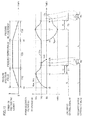
- Fig. 11 is a timing chart describing an operation of the piezoelectric power generation module 200 in Fig. 10 .
- the horizontal axis represents time and the vertical axis schematically represents voltage waveforms including the power generation voltage Vpe and signal waveforms.
- the DC voltage Vrc output from the rectifier circuit 3 is also increased with the increase in the power generation voltage Vpe generated by the piezoelectric element 1.
- the piezoelectric element 1 outputs the positive power generation voltage Vpe and the values of the power generation voltage Vpe and the DC voltage Vrc reach the threshold voltage Vth at the time t1.
- the load switch control circuit 5 varies the logical level of the load switch control signal S6 from the low level to the high level. In response to the variation in the load switch control signal S6, the load switch 6 is set to the conduction state and the piezoelectric power generation module 200 starts supply of the DC voltage Vrc to the load 7.
- the load 7 consumes the electric charge accumulated in the smoothing capacitor 4 to perform the signal transmission process to an electronic device.
- the load switch control circuit 5 varies the load switch control signal S6 from the high level H to the low level L to set the load switch 6 to the cut-off state and stops the supply of the DC voltage Vrc to the load 7.
- the values of the DC voltage Vrc and the power generation voltage Vpe are varied in the same manner.
- the piezoelectric element 1 At the time t4 when the application of the pressure to the piezoelectric element 1 is released, the piezoelectric element 1 outputs the negative power generation voltage Vpe, and the rectifier circuit 3 rectifies the negative power generation voltage Vpe to charge the smoothing capacitor 4 and outputs the DC voltage Vrc.
- the value of the DC voltage Vrc and the absolute value of the power generation voltage Vpe start to be decreased due to the current consumption in the load 7.
- the load 7 starts the signal transmission process.
- the logical level of the load switch control signal S6 is varied from the high level H to the low level L.
- the discharge switch control circuit 8 In response to the variation in the load switch control signal S6, the discharge switch control circuit 8 generates a one-shot pulse having a pulse width corresponding to the time period T4 as the discharge switch control signal S2.
- the discharge switch 2 makes a short circuit between the first signal line Tpe1 and the second signal line Tpe2. After a time t7, the value of the power generation voltage Vpe is rapidly increased to zero.
- the piezoelectric element is made of PZT ceramics in the above embodiments, the piezoelectric element is not limited to this.
- the piezoelectric element may be made of a non-lead based piezoelectric ceramic material, such as potassium-sodium niobate-based ceramics or alkali niobate based ceramics.
- the supporting structure of the piezoelectric element 1 is not limited to this.
- the piezoelectric element 1 may have a structure in which one end portion of the piezoelectric element 1 is supported by a cantilever and stress is applied to the other end portion, which is a free end.
- the piezoelectric element 1 may have a bar shape in which one end portion of the piezoelectric element 1 is supported by a cantilever and stress is applied to the other end portion.
- any supporting mode may be used as long as the piezoelectric element 1 is capable of being deformed in response to application of pressure.
Landscapes
- Engineering & Computer Science (AREA)
- Computer Networks & Wireless Communication (AREA)
- Physics & Mathematics (AREA)
- General Physics & Mathematics (AREA)
- General Electrical Machinery Utilizing Piezoelectricity, Electrostriction Or Magnetostriction (AREA)
Abstract
Description
- The present invention relates to a piezoelectric power generation module and a remote controller having the piezoelectric power generation module mounted therein. For example, the present invention relates to a piezoelectric power generation module that converts mechanical energy applied to a piezoelectric element into electrical energy and supplies power to a processing circuit and to a remote controller having the piezoelectric power generation module mounted therein.
- Configurations to improve the power generation efficiency have been proposed for power supply apparatuses including piezoelectric elements that do not require batteries. For example,
Patent Document 1 discloses a power generation apparatus including a power generation unit that generates power in response to application of strain to a piezoelectric element and a rectification unit that rectifies alternating-current (AC) voltage output from the power generation unit to output direct-current (DC) voltage. A configuration is disclosed in which the AC voltage generated by the piezoelectric element is rectified and smoothed with the rectification unit including a diode bridge and a smoothing capacitor and is converted into the DC voltage. - Patent Document 1: International Publication No.
2003/025969 -
Fig. 7 andFig. 8 illustrate a comparative example of the present invention. A piezoelectricpower generation module 100R includes apiezoelectric element 1, arectifier circuit 3, asmoothing capacitor 4, a loadswitch control circuit 5, aload switch 6, an output node N1, and an output node N2. Aload 7 is connected between the output node N1 and the output node N2. In such a configuration in which electric charge generated by thepiezoelectric element 1 is moved to theload 7 via therectifier circuit 3, which is a full-wave rectifier circuit, the electric charge is capable of being supplied to a subsequent unit in both an operation to apply pressure to thepiezoelectric element 1 and an operation to release the application of the pressure to thepiezoelectric element 1. In other words, the electric charge generated by thepiezoelectric element 1 is capable of being supplied to a subsequent unit at both positive voltage generated when thepiezoelectric element 1 is deformed with respect to reference voltage in a state in which thepiezoelectric element 1 is not deformed, and negative voltage generated when thepiezoelectric element 1 is moved to the state in which thepiezoelectric element 1 is not deformed with respect to reference voltage in a state in which thepiezoelectric element 1 is deformed. - However, for example, in a system including a semiconductor integrated circuit as the
load 7, when the voltage exceeds a certain threshold voltage in the deformation of thepiezoelectric element 1, a high impedance state occurs when power generation voltage is lower than or equal to a minimum voltage at which theload 7 is capable of being normally driven and the voltage output from thepiezoelectric element 1 is biased at a certain voltage. Accordingly, when the electric charge generated when the deformation of the piezoelectric element is returned to a normal state is to be continuously supplied to a subsequent unit, the power generation voltage is decreased. In addition, when the capacitance of thepiezoelectric element 1 is made higher than that of thesmoothing capacitor 4 in order to improve the power generation efficiency, the voltage does not reach the threshold voltage at which theload switch 6 is capable of operating in the worst case. Accordingly, there is a problem in that the piezoelectric power generation module is not capable of being stably driven in both the operation to apply pressure to the piezoelectric element and the operation to release the application of the pressure to the piezoelectric element. Solution to Problem - The present invention provides a piezoelectric power generation module including a piezoelectric element including a first terminal and a second terminal; a discharge mechanism connected in parallel to the piezoelectric element; a rectifier circuit including an input terminal pair connected to the first terminal and the second terminal and an output terminal pair that outputs direct-current voltage; a switch control circuit including a first input terminal connected to one output terminal of the rectifier circuit, a second input terminal connected to the other output terminal of the rectifier circuit, and an output terminal that outputs a switch control signal; a capacitive element connected in parallel to the first input terminal and the second input terminal of the switch control circuit; and a first switch that is connected to the one output terminal of the rectifier circuit and that switches between a conduction state and a cut-off state in response to the switch control signal. After the first switch is set to the conduction state, the discharge mechanism is set to the conduction state.
- With the above configuration, the discharge mechanism using the voltage at both ends of the piezoelectric element as reference voltage is provided in parallel to the piezoelectric element. The discharge mechanism is set to the conduction state before a state of application of pressure to the piezoelectric element is changed. Accordingly, the direct-current voltage is increased to a threshold voltage necessary for switching the first switch in both an operation to apply pressure to the piezoelectric element and an operation to release the application of pressure to the piezoelectric element. Consequently, it is possible to realize the piezoelectric power generation module capable of stable driving in both the operation to apply pressure to the piezoelectric element and the operation to release the application of pressure to the piezoelectric element.
- The piezoelectric power generation module preferably includes a load provided downstream of the first switch. After a process by the load is terminated, the discharge mechanism is preferably set to the conduction state. With this configuration, the efficiency of the power generation is further improved.
- An electrostatic capacity of the piezoelectric element is preferably greater than or equal to an electrostatic capacity of the capacitive element. With this configuration, since the amount of power generated through one operation is increased, the efficiency of the power generation is further improved.
- The discharge mechanism is preferably a second switch.
- The discharge mechanism preferably switches between the conduction state and the cut-off state using a control signal supplied from the load.
- The piezoelectric power generation module preferably further includes a control circuit that output a control signal. The discharge mechanism preferably switches between the conduction state and the cut-off state using the control signal supplied from the control circuit on the basis of the conduction state of the first switch. With this configuration, it is possible to control the piezoelectric power generation module more efficiently.
- The present invention provides a remote controller including the piezoelectric power generation module and a radio-frequency circuit. The radio-frequency circuit performs a process upon supply of the direct-current voltage from the first switch to the load. After the process is terminated, the discharge mechanism is set to the conduction state.
- With the above configuration, the discharge mechanism using the voltage at both ends of the piezoelectric element as the reference voltage is provided in parallel to the piezoelectric element. The discharge mechanism is set to the conduction state before a state of application of pressure to the piezoelectric element is changed. Accordingly, the direct-current voltage is increased to a threshold voltage necessary for switching the first switch in both an operation to apply pressure to the piezoelectric element and an operation to release the application of pressure to the piezoelectric element. Consequently, it is possible to realize the remote controller capable of supplying necessary power generation voltage to the load capable of stable driving in both the operation to apply pressure to the piezoelectric element and the operation to release the application of pressure to the piezoelectric element.
- According to the present invention, it is possible to realize the piezoelectric power generation module and the remote controller capable of stable driving in both the operation to apply pressure to the piezoelectric element and the operation to release the application of pressure to the piezoelectric element.
-
- [
Fig. 1] Fig. 1 is a circuit diagram of a piezoelectric power generation module according to a first embodiment. - [
Fig. 2] Fig. 2 includes cross-sectional views for describing the relationship between a state of application of pressure to a piezoelectric element in the piezoelectric power generation module according to the first embodiment and electric charge that is generated. - [
Fig. 3] Fig. 3 is a cross-sectional view of a piezoelectric element according to a modification of the first embodiment. - [
Fig. 4] Fig. 4 is a circuit diagram of a load switch control circuit in the piezoelectric element according to the first embodiment. - [
Fig. 5] Fig. 5 is a flowchart illustrating a processing flow of the piezoelectric power generation module according to the first embodiment. - [
Fig. 6] Fig. 6 is a timing chart describing an operation of the piezoelectric power generation module according to the first embodiment. - [
Fig. 7] Fig. 7 is a circuit diagram of a piezoelectric power generation module according to a comparative example. - [
Fig. 8] Fig. 8 is a timing chart describing an operation of the piezoelectric power generation module according to the comparative example. - [
Fig. 9] Fig. 9 is a circuit diagram of a piezoelectric power generation module according to a second embodiment. - [
Fig. 10] Fig. 10 is a flowchart illustrating a processing flow of the piezoelectric power generation module according to the second embodiment. - [
Fig. 11] Fig. 11 is a timing chart describing an operation of the piezoelectric power generation module according to the second embodiment. - Embodiments will herein be described with reference to the attached drawings. In the description of the embodiments, the number of pieces, the quantity, and so on that are referred to are not necessarily limited to those in the description unless otherwise specified. The same reference symbols and numerals are used to identify the same components or similar components in the drawings of the embodiments. A duplicated description may not be repeated for the components and so on to which the same reference symbols and the likes are added in the description of the embodiments.
-
Fig. 1 is a circuit diagram of a piezoelectricpower generation module 100 according to a first embodiment. - The piezoelectric
power generation module 100 includes apiezoelectric element 1, adischarge switch 2, arectifier circuit 3, asmoothing capacitor 4, a loadswitch control circuit 5, aload switch 6, an output node N1, an output node N2, and an input node Np. - A
load 7 is connected between the output node N1 and the output node N2. Theload 7 is, for example, a radio-frequency (RF) circuit or a processing circuit such as a microcomputer. Power supply voltage is supplied to such a processing circuit from the output node N1 and the output node N2 of the piezoelectricpower generation module 100 and the processing circuit outputs a signal (an identification code identifier (ID) or the like) to control an electronic device that is positioned apart from the piezoelectricpower generation module 100. Accordingly, the connection of theload 7 to the piezoelectricpower generation module 100 realizes a remote controller or a wireless switch. Thedischarge switch 2 corresponds to a discharge mechanism of the present invention. The smoothingcapacitor 4 corresponds to a capacitive element of the present invention. The loadswitch control circuit 5 corresponds to a switch control circuit of the present invention. Theload switch 6 corresponds to a first switch of the present invention. -
Fig. 2 includes cross-sectional views for describing the relationship between a state of application of pressure to thepiezoelectric element 1 in the piezoelectricpower generation module 100 according to the first embodiment and electric charge that is generated. -
Fig. 2(a) is a cross-sectional view schematically illustrating a state of thepiezoelectric element 1 when no stress is applied. Thepiezoelectric element 1 includes apiezoelectric body 1C and ametal plate 1D. Thepiezoelectric body 1C has a planar shape and is made of, for example, lead zirconate titanate (PZT) ceramics. Anelectrode 1A is provided on one main face of thepiezoelectric body 1C and anelectrode 1B is provided on the other main face thereof. In thepiezoelectric element 1, themetal plate 1D is electrically connected to thepiezoelectric body 1C via theelectrode 1B. Theelectrode 1A is connected to a first signal line Tpe1 and themetal plate 1D is connected to a second signal line Tpe2. As illustrated inFig. 2(b) , both ends of thepiezoelectric element 1 are supported bysupports 1E. Thepiezoelectric element 1 is polarized in response to stress applied in an arrow direction inFig. 2(b) . Theelectrode 1A corresponds to a first terminal of the piezoelectric element of the present invention. Theelectrode 1B corresponds to a second terminal of the piezoelectric element of the present invention. -
Fig. 2(b) schematically illustrates a cross-sectional view of thepiezoelectric element 1 in a state in which load is applied. Upon application of pressure (application of stress) to a central portion of thepiezoelectric element 1, mechanical energy is converted into electrical energy.Fig. 2(b) illustrates how thepiezoelectric body 1C in thepiezoelectric element 1 is polarized due to deformation caused by the application of the pressure to cause theelectrode 1A connected to the first signal line Tpe1 to be positively charged and cause theelectrode 1B connected to the second signal line Tpe2 to be negatively charged. -
Fig. 2(c) illustrates a state in which the state inFig. 2(b) returns to the state inFig. 2(a) while the application of pressure to thepiezoelectric element 1 is being released, that is, in response to release of the stress applied to thepiezoelectric element 1. Specifically, in the state illustrated inFig. 2(c) , theelectrode 1A of thepiezoelectric body 1C, which is connected to the first signal line Tpe1, is negatively charged and theelectrode 1B of thepiezoelectric body 1C, which is connected to the second signal line Tpe2, is positively charged in thepiezoelectric element 1 the application of pressure to which is being released. - Upon application of pressure (upon application of stress) to the
piezoelectric element 1, the voltage of the first signal line Tpe1 is increased, compared with that of the second signal line Tpe2. Power generation voltage Vpe is generated in the first signal line Tpe1. The power generation voltage Vpe generated while pressure is being applied to thepiezoelectric element 1 may be hereinafter described as "the positive power generation voltage Vpe". In contrast, when the application of pressure to thepiezoelectric element 1 is released (the stress is released), the voltage of first signal line Tpe1 is decreased, compared with that of the second signal line Tpe2. The power generation voltage Vpe is generated in the second signal line Tpe2. The power generation voltage Vpe generated while the application of pressure is being released may be hereinafter described as "the negative power generation voltage Vpe". In other words, AC voltage is generated between the first signal line Tpe1 and the second signal line Tpe2 in response to application of pressure to thepiezoelectric element 1 and release of the application of the pressure to thepiezoelectric element 1. - The
discharge switch 2 inFig. 1 is connected in parallel to thepiezoelectric element 1 and a conduction state of thedischarge switch 2 is controlled in response to an output port signal Sp supplied to the input node Np. Thedischarge switch 2 is an electronic switch. - The
rectifier circuit 3 is a general full-wave rectifier circuit including a diode bridge. One terminal of an input terminal pair of therectifier circuit 3 is connected to the first signal line Tpe1 and the other terminal of the input terminal pair thereof is connected to the second signal line Tpe2. The smoothingcapacitor 4 is connected between the terminals of an output terminal pair of therectifier circuit 3. The power generation voltage Vpe applied to the input terminal pair of therectifier circuit 3 is subjected to full-wave rectification in the diode bridge, is subjected to smoothing in the smoothingcapacitor 4, and is converted into direct current (DC) voltage Vrc. The DC voltage is output from the output terminal pair of therectifier circuit 3. In the output terminal pair of therectifier circuit 3, the terminal at the low voltage side is set to GND. - A power supply node Nc1 of the load
switch control circuit 5 is connected to the terminal at the high voltage side of the output terminal pair of therectifier circuit 3 and a power supply node Nc2 of the loadswitch control circuit 5 is connected to the terminal at the low voltage side of the output terminal pair of therectifier circuit 3. The power supply node Nc2 is connected to the output node N2. The loadswitch control circuit 5 outputs a load switch control signal S6 from an output terminal of theload switch 6 to switch theload switch 6 between the conduction state and a cut-off state. - One end and the other end of the
load switch 6 are connected to the power supply node Nc1 of the loadswitch control circuit 5 and the output node N1, respectively. Theload switch 6 may be arranged between the power supply node Nc2 and the output node Nc2, instead of the arrangement of theload switch 6 between the power supply node Nc1 and the output node N1. -
Fig. 4 is a circuit diagram of the loadswitch control circuit 5 in the piezoelectricpower generation module 100 inFig. 1 . - The load
switch control circuit 5 is composed of, for example, a complementary metal oxide semiconductor (CMOS) circuit. The loadswitch control circuit 5 has a first input terminal connected to the power supply node Nc1, a second input terminal connected to the power supply node Nc2, and an output terminal. The loadswitch control circuit 5 includes a resonator R1, a resonator R2, and a resonator R3 connected in series in this order from the power supply node Nc1 side between the power supply node Nc1 and the power supply node Nc2. In addition, the loadswitch control circuit 5 includes aswitch 51, a comparisonvoltage generating circuit 53, and acomparator circuit 52. Theswitch 51 is, for example, an electronic switch. The comparisonvoltage generating circuit 53 is, for example, a band gap reference. Thecomparator circuit 52 is, for example, an operational amplifier. - One end of the resonator R1 is connected to the power supply node Nc1 and the other end thereof is connected to one end of the resonator R2. The one end of the resonator R2 is connected to the other end of the resonator R1 and the other end thereof is connected to one end of the resonator R3. The one end of the resonator R3 is connected to the other end of the resonator R2 and the other end thereof is connected to the power supply node Nc2. One end of the
switch 51 is connected to the power supply node Nc1 and the other end thereof is connected to the other end of the resonator R1. An input terminal of the comparisonvoltage generating circuit 53 is connected to the power supply node Nc2 and an output terminal thereof is connected to an inverting input terminal of thecomparator circuit 52. A non-inverting input terminal of thecomparator circuit 52 is connected to the one end of the resonator R3 and an output terminal thereof is connected to theswitch 51 and theload switch 6. - The load
switch control circuit 5 varies a logical level of the load switch control signal S6 to be output depending on variation in the DC voltage Vrc applied between the power supply node Nc1 and the power supply node Nc2. Theload switch 6 is set to the conduction state (on state) when the logical level of the load switch control signal S6 is set to a high level and is set to the cut-off state (off state) when the logical level of the load switch control signal S6 is set to a low level. - When the
load switch 6 is set to the conduction state, the DC voltage Vrc generated between the output node N1 and the output node N2 is supplied to theload 7. The amount of electric charge accumulated in the smoothingcapacitor 4 is gradually decreased in accordance with current consumption in theload 7 to decrease the value of the DC voltage Vrc. The voltage of the second signal line Tpe2 in a state in which thepiezoelectric element 1 is not deformed corresponds to reference voltage GND of the present invention. - The load
switch control circuit 5 is set so that the variation in the logical level of the load switch control signal S6 to be output from the loadswitch control circuit 5 has hysteresis characteristics with respect to the variation in the DC voltage Vrc input between the power supply node Nc1 and the power supply node Nc2. The hysteresis characteristics are realized by switching the conduction state of theswitch 51 using the load switch control signal S6 output from thecomparator circuit 52. - When the value of the DC voltage Vrc is increased from zero to a threshold voltage Vth, the
load switch 6 is varied from the off state to the on state. Then, when the value of the DC voltage Vrc is decreased to a threshold voltage Vtl lower than the threshold voltage Vth in association with the supply of current to theload 7, theload switch 6 is varied from the conduction state to the cut-off state. - When the
switch 51 is in the cut-off state, the DC voltage Vrc is divided among the resonators R1, R2, and R3 connected in series between the power supply node Nc1 and the power supply node Nc2. Thecomparator circuit 52 compares the voltage between both ends of the resonator R3 and the voltage generated by the comparisonvoltage generating circuit 53 to determine the logical level of the load switch control signal S6. The values of the resonators R1 to R3 and the value of the comparison voltage are appropriately set so that the threshold voltage Vth (refer toFig. 1 ) has a desired value. When the value of the DC voltage Vrc exceeds the threshold voltage Vth, thecomparator circuit 52 varies the logical level of the load switch control signal S6 from the low level to the high level. Theload switch 6 is set to the conduction state in response to the variation in the load switch control signal S6 and the DC voltage Vrc is applied between the output node N1 and the output node N2 (refer toFig. 1 ). - When the load switch control signal S6 is set to the high level, the
switch 51 connected in parallel to the resonator R1 is also set to the conduction state and the voltage of the power supply node Nc1 (the DC voltage Vrc) is divided between the resonator R2 and the resonator R3. Since the value of the voltage between both ends of the resonator R3 is increased, compared with the case in which theswitch 51 is in the cut-off state, thecomparator circuit 52 varies the logical level of the load switch control signal S6 from the high level to the low level when the value the DC voltage Vrc reaches the threshold voltage Vtl lower than the threshold voltage Vth. Theload switch 6 is set to the cut-off state in response to the variation in the load switch control signal S6 and the supply of the DC voltage Vrc to the output node N1 is stopped. -
Fig. 5 is a flowchart illustrating a processing flow of the piezoelectricpower generation module 100 inFig. 1 . - The processing flow of the piezoelectric
power generation module 100 will now be described with reference toFig. 5 andFig. 1 . - Upon application of pressure to the piezoelectric element 1 (upon generation of the positive power generation voltage Vpe) or upon release of application of pressure to the piezoelectric element 1 (upon generation of the negative power generation voltage Vpe), the power generation voltage Vpe is applied between the terminals of the input terminal pair of the rectifier circuit 3 (Step S11). The power generation voltage Vpe rectified by the
rectifier circuit 3 is smoothed by the smoothingcapacitor 4 to generate the DC voltage Vrc (Step S12). The loadswitch control circuit 5 determines whether the value of the DC voltage Vrc that is applied reaches the threshold voltage Vth (Step S13). - If the value of the DC voltage Vrc is lower than the threshold voltage Vth ("NO" in Step S13), the
load switch 6 is set to the cut-off state and therectifier circuit 3 continuously charges the smoothingcapacitor 4. If the value of the DC voltage Vrc reaches the threshold voltage Vth ("YES" in Step S13), the loadswitch control circuit 5 sets theload switch 6 to the conduction state using the load switch control signal S6 (Step S14). - The DC voltage Vrc is supplied to the
load 7 via theload switch 6 and the output node N1. Theload 7 performs a signal transmission process to an electronic device (Step S15). Then, theload 7 supplies the output port signal Sp to the input node Np. Thedischarge switch 2 is set to the conduction state in response to the output port signal Sp and a short circuit is made between the first signal line Tpe1 the second signal line Tpe2. The electric charge accumulated in thepiezoelectric element 1 at this time is discharged in thepiezoelectric element 1 and the value of the power generation voltage Vpe is set to zero (Step S16). - The load
switch control circuit 5 compares the value of the DC voltage Vrc that is applied with the threshold voltage Vtl (Step S17). If the value of the DC voltage Vrc is higher than or equal to the threshold voltage Vtl ("NO" in Step S17), the conduction state of theload switch 6 is kept. If the value of the DC voltage Vrc is lower than the threshold voltage Vtl ("YES" in Step S17), the loadswitch control circuit 5 sets theload switch 6 to the cut-off state using the load switch control signal S6 (Step S18). Upon setting of theload switch 6 to the cut-off state, the supply of the DC voltage Vrc to theload 7 is stopped and theload 7 is powered down. -
Fig. 6 is a timing chart describing an operation of the piezoelectricpower generation module 100 inFig. 1 . - The operation of the piezoelectric
power generation module 100 will now be described with reference toFig. 6 andFig. 1 . Referring toFig. 6 , the horizontal axis represents time and the vertical axis schematically represents voltages including the power generation voltage Vpe and signals. The operation of the piezoelectricpower generation module 100 illustrated inFig. 6 is divided into operations in three continuous periods: 1) application of pressure to thepiezoelectric element 1 during a pressure application period T10, 2) keeping of the application of the pressure to thepiezoelectric element 1 during a pressure keeping period T20, and 3) release of the application of the pressure to thepiezoelectric element 1 during a pressure release period T30. - At start of application of pressure to the
piezoelectric element 1 at a time t0, the DC voltage Vrc output from therectifier circuit 3 is also increased with the increase in the power generation voltage Vpe generated by thepiezoelectric element 1. During the pressure application period to thepiezoelectric element 1, which is started at the time t0, thepiezoelectric element 1 outputs the positive power generation voltage Vpe. The values of the power generation voltage Vpe and the DC voltage Vrc reach the threshold voltage Vth at a time t1. When the value of the DC voltage Vrc reaches the threshold voltage Vth, the loadswitch control circuit 5 varies the logical level of the load switch control signal S6 from a low level L to a high level H. In response to the variation in the load switch control signal S6, theload switch 6 is set to the conduction state and the piezoelectricpower generation module 100 starts supply of the DC voltage Vrc to theload 7. - After the time t1, the
load 7 consumes the electric charge accumulated in the smoothingcapacitor 4 to perform a certain process (the signal transmission process to an electronic device) and terminates the process by a time t2. After the time t2, theload 7 keeps an idle state. When the value of the DC voltage Vrc reaches the threshold voltage Vtl at a time t3, the loadswitch control circuit 5 varies the load switch control signal S6 to the low level L to set theload switch 6 to the cut-off state and stops the supply of the DC voltage Vrc to theload 7. - In contrast, the power generation voltage Vpe is varied in the following manner. Upon completion of the signal transmission process started at the time t1 at the time t2, the
load 7 supplies the output port signal Sp to the input node Np. Thedischarge switch 2 is varied from the cut-off state to the conduction state in response to the output port signal Sp. A short circuit is made between the first signal line Tpe1 and the second signal line Tpe2 and the electric charge accumulated in thepiezoelectric element 1 at this time is discharged. After the time t2, the value of the power generation voltage Vpe is rapidly decreased to zero. In contrast, the DC voltage Vrc is gradually decreased in association with the supply of the power to the load, which is in the idle state. - The pressure keeping period T20 is a period during which certain stress is applied to the
piezoelectric element 1. For example, during the pressure keeping period T20, thepiezoelectric element 1 to which pressure is applied from one direction is pressed against a fixing unit arranged at the other direction side and thepiezoelectric element 1 is kept in a state in which the amount of strain generated in thepiezoelectric element 1 is hardly varied.Fig. 6 illustrates a state in which, before start of the pressure keeping period T20, the power generation voltage Vpe is set to zero by thedischarge switch 2 described above and no power is supplied to the load. As described above, during the pressure application period T20, the DC voltage Vrc is gradually decreased to the predetermined threshold voltage Vtl. - At the time t3 when the DC voltage Vrc reaches Vtl, the load
switch control circuit 5 varies the load switch control signal S6 from the high level H to the low level L. This stops the supply of the DC voltage Vrc to theload 7 and the voltage of the output port signal Sp applied to the input node Np is varied from the high level H set by theload 7 to the low level L set by a pull-down resistor (not illustrated). - Upon release of the application of the pressure to the
piezoelectric element 1 at a time t4, thepiezoelectric element 1 outputs the negative power generation voltage Vpe, and therectifier circuit 3 rectifies the negative power generation voltage Vpe and outputs the DC voltage Vrc. At a time t5 when the power generation voltage Vpe reaches the negative threshold voltage Vth and the DC voltage Vrc reaches the (positive) threshold voltage Vth, the value of the DC voltage Vrc and the absolute value of the power generation voltage Vpe start to be decreased due to the current consumption in theload 7. As well as during the pressure application period T10, after the time t5, theload 7 starts the signal transmission process. At a time t6 when the process is completed, theload 7 supplies the output port signal Sp to the input node Np. - The
discharge switch 2 makes a short circuit between the first signal line Tpe1 and the second signal line Tpe2 in response to the output port signal Sp and, after the time t6, the value of the power generation voltage Vpe rapidly reaches zero. A time period T3 and a time period T4 correspond to a time period T1 and a time period T2, respectively. A duplicated description of the time period T3 and the time period T4 is omitted herein. - As described above, with the piezoelectric
power generation module 100, the power supply voltage is capable of being supplied to theload 7 connected between the output node N1 and the output node N2 of the piezoelectricpower generation module 100 during both the pressure application period and the pressure release period of thepiezoelectric element 1. -
Fig. 7 is a circuit diagram of the piezoelectricpower generation module 100R according to the comparative example of the piezoelectricpower generation module 100 inFig. 1 . - The same reference numerals are used in
Fig. 7 to identify the same components or functions illustrated inFig. 1 . A duplicated description of such components and functions is omitted herein. The piezoelectricpower generation module 100R inFig. 7 is the comparative example for describing the advantages of the piezoelectricpower generation module 100 inFig. 1 . The piezoelectricpower generation module 100R has a configuration in which thedischarge switch 2, the input node Np, and the output port signal Sp are removed from the piezoelectricpower generation module 100 inFig. 1 . In other words, in the piezoelectricpower generation module 100R, the discharge of thepiezoelectric element 1 is not performed after the processing operation by theload 7 is completed. -
Fig. 8 is a timing chart describing an operation of the piezoelectricpower generation module 100R inFig. 7 . - The operation of the piezoelectric
power generation module 100R will now be described with reference toFig. 8 andFig. 7 . - Referring to
Fig. 8 , the waveform of the DC voltage Vrc during the time period from the time t0 to the time t3 is the same as the waveform of the DC voltage Vrc during the same time period inFig. 6 . In other words, at start of application of pressure to thepiezoelectric element 1 at the time t0, both of the values of the power generation voltage Vpe and the DC voltage Vrc reach the threshold voltage Vth at the time t1. After the time t1, theload 7 enters the idle state after performing the signal transmission process. At the time t3, the value of the DC voltage Vrc reaches the threshold voltage Vtl. - Referring to
Fig. 6 , after the time t2, the power generation voltage Vpe is rapidly decreased to zero with thedischarge switch 2 set in the conduction state. In contrast, referring toFig. 8 , after the time t2, the waveform of the power generation voltage Vpe is the same as the waveform of the DC voltage Vrc. This is because the piezoelectricpower generation module 100R does not include thedischarge switch 2, which discharges thepiezoelectric element 1. - In addition, referring to
Fig. 6 , after the time t2, the value of the power generation voltage Vpe, which has been decreased to zero, is kept at zero until the time t4 when the application of the pressure to thepiezoelectric element 1 is released. In contrast, referring toFig. 8 , after the time t3, the values of the power generation voltage Vpe and the DC voltage Vrc are kept at a voltage value slightly higher than the threshold voltage Vtl. This is because the power generation voltage Vpe generated by thepiezoelectric element 1 is applied to the smoothingcapacitor 4 via therectifier circuit 3 during the pressure keeping period T20. - At the time t4 when the application of the pressure to the
piezoelectric element 1 is released, thepiezoelectric element 1 starts to output the negative power generation voltage Vpe from the state in which thepiezoelectric element 1 keeps the positive power generation voltage Vpe slightly higher than the threshold voltage Vtl and the voltage corresponding to the threshold voltage Vth is generated in the second signal line Tpe2. However, since a voltage value slightly higher than the threshold voltage Vtl is generated in the second signal line Tpe2 at the time t4, the negative power generation voltage Vpe of thepiezoelectric element 1, which is supplied to therectifier circuit 3, is slightly lower than zero. - Accordingly, the
piezoelectric element 1 is not capable of charging the smoothingcapacitor 4 that has been charged to a voltage higher than or equal to the threshold voltage Vtl and the value of the DC voltage Vrc does not reach the threshold voltage Vth. As a result, the cut-off state of theload switch 6 is kept and theload 7 is not capable of performing the signal transmission process. - The advantages of the piezoelectric
power generation module 100 according to the first embodiment will now be described. - In the piezoelectric
power generation module 100, therectifier circuit 3 rectifies the positive power generation voltage Vpe generated in response to the application of the pressure to thepiezoelectric element 1 and outputs the DC voltage Vrc during the pressure application period T10. When the value of the DC voltage Vrc exceeds the threshold voltage Vth, theload switch 6 is set to the conduction state and supply of the DC voltage Vrc to theload 7 is started. After the processing operation by theload 7 is completed, thedischarge switch 2 connected in parallel to thepiezoelectric element 1 makes a short circuit between the first signal line Tpe1 and the second signal line Tpe2 in response to the output port signal Sp output from theload 7 and the value of the power generation voltage Vpe of thepiezoelectric element 1 is reset to zero. - Then, the
rectifier circuit 3 rectifies the negative power generation voltage Vpe generated in response to release of the application of the pressure to thepiezoelectric element 1 and outputs the DC voltage Vrc during the pressure release period T30. Since the power generation voltage Vpe of thepiezoelectric element 1 is reset to zero by thedischarge switch 2 before thepiezoelectric element 1 generates the negative power generation voltage Vpe, the value of the power generation voltage Vpe output from thepiezoelectric element 1 is increased to the threshold voltage Vth necessary for operating theload 7, as well as during the pressure application period T10. - Accordingly, the
load 7 is capable of performing a desired processing operation also during the pressure release period T30, as well as during the pressure application period T10. For example, dimmer control of a lighting switch and opening-closing control of a blind are capable of being performed with one series of the pressure application operation and the pressure release operation to thepiezoelectric element 1. -
Fig. 3 is a cross-sectional view of apiezoelectric element 11 according to another example of thepiezoelectric element 1 inFig. 2 . - The same reference numerals are used in
Fig. 3 to identify the same components or functions illustrated inFig. 2 . A duplicated description of such components and functions is omitted herein. Referring toFig. 3 , thepiezoelectric element 11 has a structure in which piezoelectric bodies 11C are laminated so that electric charges having the same polarity are generated on the faces which the respective piezoelectric bodies 11C oppose during application of pressure. The laminating structure of thepiezoelectric element 11 increases the amount of electric charge generated by thepiezoelectric element 11 to allow the load 7 (refer toFig. 1 ) to be driven for a longer time period. -
Fig. 9 is a circuit diagram of a piezoelectricpower generation module 200 according to a second embodiment. - The same reference numerals are used in
Fig. 9 to identify the same components or functions illustrated inFig. 1 . A duplicated description of such components and functions is omitted herein. In the piezoelectricpower generation module 200 illustrated inFig. 9 , control of the conduction state of thedischarge switch 2 is performed on the basis of a discharge switch control signal S2 output from a dischargeswitch control circuit 8, instead of the output port signal Sp output from theload 7. Accordingly, the piezoelectricpower generation module 200 does not include the input node Np provided in the piezoelectricpower generation module 100 inFig. 1 . - The discharge
switch control circuit 8 operates upon reception of the DC voltage Vrc supplied from therectifier circuit 3 and outputs a one-shot pulse having a certain pulse width as the discharge switch control signal S2 in response to a falling edge of the load switch control signal S6. Thedischarge switch 2 is set to the conduction state during a time period when the discharge switch control signal S2 is set to the high level to make a short circuit between the first signal line Tpe1 and the second signal line Tpe2. -
Fig. 10 is a flowchart illustrating a processing flow of the piezoelectricpower generation module 200 inFig. 9 . - The processing flow of the piezoelectric
power generation module 200 will now be descried with reference toFig. 10 andFig. 9 . Steps S21 to S25 are the same as Steps S11 to S15 illustrated inFig. 5 . - Upon application of pressure to the piezoelectric element 1 (upon generation of the positive power generation voltage Vpe) or upon release of application of pressure to the piezoelectric element 1 (upon generation of the negative power generation voltage Vpe), the power generation voltage Vpe is applied between the terminals of the input terminal pair of the rectifier circuit 3 (Step S21). The power generation voltage Vpe rectified by the
rectifier circuit 3 is smoothed by the smoothingcapacitor 4 to generate the DC voltage Vrc (Step S22). The loadswitch control circuit 5 determines whether the value of the DC voltage Vrc that is applied reaches the threshold voltage Vth (Step S23). - If the value of the DC voltage Vrc is lower than the threshold voltage Vth ("NO" in Step S23), the
load switch 6 is set to the cut-off state and therectifier circuit 3 continuously charges the smoothingcapacitor 4. If the value of the DC voltage Vrc reaches the threshold voltage Vth ("YES" in Step S23), the loadswitch control circuit 5 sets theload switch 6 to the conduction state using the load switch control signal S6 (Step S24). - The DC voltage Vrc is supplied to the
load 7 via theload switch 6 and the output node N1. Theload 7 performs the signal transmission process to an electronic device (Step S25). The loadswitch control circuit 5 compares the value of the DC voltage Vrc that is applied with the threshold voltage Vtl (Step S26). If the value of the DC voltage Vrc is higher than or equal to the threshold voltage Vtl ("NO" in Step S26), the conduction state of theload switch 6 is kept. If the value of the DC voltage Vrc is lower than the threshold voltage Vtl ("YES" in Step S26), the loadswitch control circuit 5 sets theload switch 6 to the cut-off state using the load switch control signal S6 (Step S27). - After the
load switch 6 is set to the cut-off state, the dischargeswitch control circuit 8 generates a one-shot pulse as the discharge switch control signal S2, sets thedischarge switch 2 to the conduction state during a certain time period, and discharge the electric charge in the piezoelectric element 1 (Step S28). This discharge resets the value of the power generation voltage Vpe of thepiezoelectric element 1 to zero. -
Fig. 11 is a timing chart describing an operation of the piezoelectricpower generation module 200 inFig. 10 . - The operation of the piezoelectric
power generation module 200 will now be described with reference toFig. 11 andFig. 9 . Referring toFig. 11 , the horizontal axis represents time and the vertical axis schematically represents voltage waveforms including the power generation voltage Vpe and signal waveforms. - At start of application of pressure to the
piezoelectric element 1 at the time t0, the DC voltage Vrc output from therectifier circuit 3 is also increased with the increase in the power generation voltage Vpe generated by thepiezoelectric element 1. During the pressure application period to thepiezoelectric element 1, which is started at the time t0, thepiezoelectric element 1 outputs the positive power generation voltage Vpe and the values of the power generation voltage Vpe and the DC voltage Vrc reach the threshold voltage Vth at the time t1. - When the value of the DC voltage Vrc reaches the threshold voltage Vth, the load
switch control circuit 5 varies the logical level of the load switch control signal S6 from the low level to the high level. In response to the variation in the load switch control signal S6, theload switch 6 is set to the conduction state and the piezoelectricpower generation module 200 starts supply of the DC voltage Vrc to theload 7. - After the time t1, the
load 7 consumes the electric charge accumulated in the smoothingcapacitor 4 to perform the signal transmission process to an electronic device. At the time t2 when the value of the DC voltage Vrc reaches the threshold voltage Vtl, the loadswitch control circuit 5 varies the load switch control signal S6 from the high level H to the low level L to set theload switch 6 to the cut-off state and stops the supply of the DC voltage Vrc to theload 7. During the time period from the time t0 to the time t2, the values of the DC voltage Vrc and the power generation voltage Vpe are varied in the same manner. - In response to the variation in the logical level of the load switch control signal S6 at the time t2, the discharge
switch control circuit 8 generates a one-shot pulse having a pulse width corresponding to the time period T2 from the time t3 to a time t3A as the discharge switch control signal S2. Thedischarge switch 2 makes a short-circuit between the first signal line Tpe1 and the second signal line Tpe2 during the time period T2 in response to the discharge switch control signal S2. As a result, the value of the power generation voltage Vpe is rapidly decreased from the threshold voltage Vtl at the time t3 to zero at the time t3A. Until the time t4 when the pressure release period T30 is started, the value of the DC voltage Vrc is kept at the threshold voltage Vtl and the value of the power generation voltage Vpe is kept at zero. - At the time t4 when the application of the pressure to the
piezoelectric element 1 is released, thepiezoelectric element 1 outputs the negative power generation voltage Vpe, and therectifier circuit 3 rectifies the negative power generation voltage Vpe to charge the smoothingcapacitor 4 and outputs the DC voltage Vrc. At the time t5 when the power generation voltage Vpe reaches the threshold voltage Vth and the DC voltage Vrc reaches the negative threshold voltage Vth (-Vth), the value of the DC voltage Vrc and the absolute value of the power generation voltage Vpe start to be decreased due to the current consumption in theload 7. - As well as after the time t1, after the time t5, the
load 7 starts the signal transmission process. At the time t6 when the DC voltage Vrc reaches the threshold voltage Vtl, the logical level of the load switch control signal S6 is varied from the high level H to the low level L. In response to the variation in the load switch control signal S6, the dischargeswitch control circuit 8 generates a one-shot pulse having a pulse width corresponding to the time period T4 as the discharge switch control signal S2. In response to the discharge switch control signal S2, thedischarge switch 2 makes a short circuit between the first signal line Tpe1 and the second signal line Tpe2. After a time t7, the value of the power generation voltage Vpe is rapidly increased to zero. - With the piezoelectric
power generation module 200, control of thedischarge switch 2 with theload 7 is not required and thedischarge switch 2 is capable of being controlled on the basis of the value of the DC voltage Vrc output from therectifier circuit 3 provided in the piezoelectricpower generation module 200. Accordingly, necessary power supply voltage is capable of being supplied also to theload 7 that does not have the output function of the output port signal in both the operation to apply pressure to thepiezoelectric element 1 and the operation to release the application of the pressure to thepiezoelectric element 1. - Although the piezoelectric element is made of PZT ceramics in the above embodiments, the piezoelectric element is not limited to this. For example, the piezoelectric element may be made of a non-lead based piezoelectric ceramic material, such as potassium-sodium niobate-based ceramics or alkali niobate based ceramics.
- Although the
piezoelectric element 1 is supported by the twosupports 1E in the above embodiments, the supporting structure of thepiezoelectric element 1 is not limited to this. For example, thepiezoelectric element 1 may have a structure in which one end portion of thepiezoelectric element 1 is supported by a cantilever and stress is applied to the other end portion, which is a free end. Alternatively, thepiezoelectric element 1 may have a bar shape in which one end portion of thepiezoelectric element 1 is supported by a cantilever and stress is applied to the other end portion. In other words, any supporting mode may be used as long as thepiezoelectric element 1 is capable of being deformed in response to application of pressure. - While the present invention has been described with reference to what are presently considered to be the preferred embodiments, it is to be understood that the invention is not limited to the disclosed embodiments. On the contrary, the invention is intended to cover various modifications and equivalent arrangements included within the spirit and scope of the appended claims. The scope of the following claims is to be accorded the broadest interpretation so as to encompass all such modifications and equivalent structures and functions.
-
- 1
- piezoelectric element
- 1A, 1B
- electrode
- 1C
- piezoelectric body
- 1D
- metal plate
- 1E
- supports
- 2
- discharge switch
- 3
- rectifier circuit
- 4
- smoothing capacitor
- 5
- load switch control circuit
- 6
- load switch
- 7
- load
- 8
- discharge switch control circuit
- 11
- piezoelectric element
- 11C
- piezoelectric bodies
- 51
- switch
- 52
- comparator circuit
- 53
- comparison voltage generating circuit
- 100, 100R, 200
- piezoelectric power generation module
- N1, N2
- output node
- Nc1, Nc2
- power supply node
- Np
- input node
- R1, R2, R3
- resonator
- S2
- discharge switch control signal
- S6
- load switch control signal
- Sp
- output port signal
- Tpe1
- first signal line
- Tpe2
- second signal line
- Vpe
- power generation voltage
- Vrc DC
- voltage
- Vth, Vtl
- threshold voltage
Claims (7)
- A piezoelectric power generation module comprising:a piezoelectric element including a first terminal and a second terminal;a discharge mechanism connected in parallel to the piezoelectric element;a rectifier circuit including an input terminal pair connected to the first terminal and the second terminal and an output terminal pair that outputs direct-current voltage;a switch control circuit including a first input terminal connected to one output terminal of the rectifier circuit, a second input terminal connected to the other output terminal of the rectifier circuit, and an output terminal that outputs a switch control signal;a capacitive element connected in parallel to the first input terminal and the second input terminal of the switch control circuit; anda first switch that is connected to the one output terminal of the rectifier circuit and that switches between a conduction state and a cut-off state in response to the switch control signal,wherein, after the first switch is set to the conduction state, the discharge mechanism is set to the conduction state.
- The piezoelectric power generation module according to Claim 1, further comprising:a load provided downstream of the first switch,wherein, after a process by the load is terminated, the discharge mechanism is set to the conduction state.
- The piezoelectric power generation module according to Claim 1 or 2,
wherein an electrostatic capacity of the piezoelectric element is greater than or equal to an electrostatic capacity of the capacitive element. - The piezoelectric power generation module according to any of Claims 1 to 3,
wherein the discharge mechanism is a second switch. - The piezoelectric power generation module according to any of Claims 1 to 4,
wherein the discharge mechanism switches between the conduction state and the cut-off state using a control signal supplied from the load. - The piezoelectric power generation module according to any of Claims 1 to 5, further comprising:a control circuit that output a control signal,wherein the discharge mechanism switches between the conduction state and the cut-off state using the control signal supplied from the control circuit on the basis of the conduction state of the first switch.
- A remote controller comprising:the piezoelectric power generation module according to any of Claims 1 to 6; anda radio-frequency circuit,wherein the radio-frequency circuit performs a process upon supply of the direct-current voltage from the first switch to the load, andwherein, after the process is terminated, the discharge mechanism is set to the conduction state.
Applications Claiming Priority (2)
| Application Number | Priority Date | Filing Date | Title |
|---|---|---|---|
| JP2014009594 | 2014-01-22 | ||
| PCT/JP2014/077670 WO2015111259A1 (en) | 2014-01-22 | 2014-10-17 | Piezoelectric power generation module and remote controller |
Publications (3)
| Publication Number | Publication Date |
|---|---|
| EP3098959A1 true EP3098959A1 (en) | 2016-11-30 |
| EP3098959A4 EP3098959A4 (en) | 2017-09-13 |
| EP3098959B1 EP3098959B1 (en) | 2018-11-14 |
Family
ID=53681082
Family Applications (1)
| Application Number | Title | Priority Date | Filing Date |
|---|---|---|---|
| EP14879817.6A Active EP3098959B1 (en) | 2014-01-22 | 2014-10-17 | Piezoelectric power generation module and remote controller |
Country Status (5)
| Country | Link |
|---|---|
| US (1) | US10014801B2 (en) |
| EP (1) | EP3098959B1 (en) |
| JP (1) | JP6103077B2 (en) |
| CN (1) | CN105850026B (en) |
| WO (1) | WO2015111259A1 (en) |
Families Citing this family (5)
| Publication number | Priority date | Publication date | Assignee | Title |
|---|---|---|---|---|
| JP6406538B2 (en) * | 2014-06-17 | 2018-10-17 | Toto株式会社 | Remote control device for toilet equipment |
| WO2017104342A1 (en) * | 2015-12-15 | 2017-06-22 | 株式会社村田製作所 | Power generation device and transmitter comprising same |
| JP6803049B2 (en) * | 2018-05-31 | 2020-12-23 | 国立大学法人 東京大学 | Power supply circuit and vibration power generator |
| JP6842092B2 (en) * | 2018-05-31 | 2021-03-17 | 国立大学法人 東京大学 | Power supply circuit and vibration power generator |
| FR3111754B1 (en) * | 2020-06-22 | 2022-07-08 | Commissariat Energie Atomique | DEVICE FOR RECOVERING OR DAMPING VIBRATIONAL ENERGY OF A RESONANT MECHANICAL ELEMENT |
Family Cites Families (17)
| Publication number | Priority date | Publication date | Assignee | Title |
|---|---|---|---|---|
| JPH07107752A (en) | 1993-09-30 | 1995-04-21 | Mitsuteru Kimura | Piezoelectric generating device |
| JP2003007491A (en) * | 2001-06-26 | 2003-01-10 | Nec Tokin Ceramics Corp | Luminescence substance lighting equipment |
| WO2003025969A1 (en) * | 2001-09-12 | 2003-03-27 | Jisouken Co., Ltd. | Power source apparatus |
| DE10221420A1 (en) * | 2002-05-14 | 2003-12-11 | Enocean Gmbh | Device for converting mechanical energy into electrical energy |
| CN100414808C (en) * | 2006-04-26 | 2008-08-27 | 中南大学 | Piezoelectric Energy Harvesters with Efficient Energy Harvesting and Storage |
| WO2008103932A1 (en) * | 2007-02-23 | 2008-08-28 | Societe De Technologie Michelin | Method for discharging capacitive loads |
| WO2009039293A1 (en) * | 2007-09-18 | 2009-03-26 | University Of Florida Research Foundation, Inc. | Dul-mode piezoelectric/magnetic vibrational energy harvester |
| US8026650B2 (en) * | 2008-09-22 | 2011-09-27 | Massachusetts Institute Of Technology | Circuit and method to improve energy harvesting efficiency in piezoelectric harvesters |
| US8674663B2 (en) * | 2010-03-19 | 2014-03-18 | Texas Instruments Incorporated | Converter and method for extracting maximum power from piezo vibration harvester |
| JP4835888B1 (en) * | 2010-11-15 | 2011-12-14 | セイコーエプソン株式会社 | Power generator |
| US8653718B2 (en) * | 2011-05-06 | 2014-02-18 | Seiko Epson Corporation | Power generation unit, electronic apparatus, transportation unit, battery, method of controlling power generation unit |
| EP2579440A1 (en) * | 2011-10-07 | 2013-04-10 | Fraunhofer-Gesellschaft zur Förderung der angewandten Forschung e.V. | Rectifier circuit with ac side short-circuiting function and synchronized switch harvesting on inductor converter |
| JP2013219940A (en) * | 2012-04-10 | 2013-10-24 | Asahi Kasei Electronics Co Ltd | Power generator |
| US9344014B2 (en) * | 2012-09-05 | 2016-05-17 | Texas Instruments Incorporated | Piezoelectric device |
| EP2922194B1 (en) * | 2012-11-19 | 2017-12-06 | Panasonic Intellectual Property Management Co., Ltd. | Power-generating device |
| CN105556825B (en) * | 2013-08-13 | 2018-03-13 | 国立大学法人东北大学 | power generation device |
| JP6098736B2 (en) * | 2014-01-22 | 2017-03-22 | 株式会社村田製作所 | Piezoelectric generator module and remote controller |
-
2014
- 2014-10-17 CN CN201480071449.5A patent/CN105850026B/en active Active
- 2014-10-17 EP EP14879817.6A patent/EP3098959B1/en active Active
- 2014-10-17 JP JP2015558734A patent/JP6103077B2/en active Active
- 2014-10-17 WO PCT/JP2014/077670 patent/WO2015111259A1/en not_active Ceased
-
2016
- 2016-07-06 US US15/202,946 patent/US10014801B2/en active Active
Also Published As
| Publication number | Publication date |
|---|---|
| JP6103077B2 (en) | 2017-03-29 |
| JPWO2015111259A1 (en) | 2017-03-23 |
| CN105850026A (en) | 2016-08-10 |
| US20160315563A1 (en) | 2016-10-27 |
| US10014801B2 (en) | 2018-07-03 |
| WO2015111259A1 (en) | 2015-07-30 |
| EP3098959A4 (en) | 2017-09-13 |
| CN105850026B (en) | 2018-06-12 |
| EP3098959B1 (en) | 2018-11-14 |
Similar Documents
| Publication | Publication Date | Title |
|---|---|---|
| EP3098959B1 (en) | Piezoelectric power generation module and remote controller | |
| EP3098866B1 (en) | Piezoelectric power generation module and remote controller | |
| CN112166546B (en) | Power supply circuit and vibration power generation device | |
| CN106160247A (en) | For wirelessly sending the equipment of electric power | |
| US10396667B2 (en) | DC-DC converter including an intermittent overcurrent protection circuit | |
| US11121648B2 (en) | Piezoelectric generator | |
| TWI606686B (en) | Actuating system for piezoelectric pump | |
| US10250074B2 (en) | Power supply system | |
| US11424673B2 (en) | Power supply circuit, start-up circuit, power generating device, and electronic apparatus | |
| US20140183965A1 (en) | Electronic component, power feeding device, and power feeding system | |
| JP6481773B2 (en) | Power generation device and transmitter having the same | |
| CN103312014A (en) | Wireless charging system and method for controlling same | |
| JP6540803B2 (en) | POWER GENERATOR AND ELECTRICAL EQUIPMENT COMPRISING THE SAME | |
| CN206759311U (en) | Automobile intelligent step-down line device | |
| US9973022B2 (en) | Non-contact type power receiving apparatus | |
| CN117389192A (en) | Power supply circuit and power supply equipment | |
| CN112910065A (en) | Charging circuit, electrical equipment and charger | |
| JPH0787730A (en) | DC-DC converter circuit | |
| EP2582006A1 (en) | Charge control device | |
| JP2019205329A (en) | Power inverter circuit and electric power unit |
Legal Events
| Date | Code | Title | Description |
|---|---|---|---|
| PUAI | Public reference made under article 153(3) epc to a published international application that has entered the european phase |
Free format text: ORIGINAL CODE: 0009012 |
|
| 17P | Request for examination filed |
Effective date: 20160603 |
|
| AK | Designated contracting states |
Kind code of ref document: A1 Designated state(s): AL AT BE BG CH CY CZ DE DK EE ES FI FR GB GR HR HU IE IS IT LI LT LU LV MC MK MT NL NO PL PT RO RS SE SI SK SM TR |
|
| AX | Request for extension of the european patent |
Extension state: BA ME |
|
| DAX | Request for extension of the european patent (deleted) | ||
| A4 | Supplementary search report drawn up and despatched |
Effective date: 20170817 |
|
| RIC1 | Information provided on ipc code assigned before grant |
Ipc: G08C 17/02 20060101ALI20170810BHEP Ipc: H02N 2/18 20060101AFI20170810BHEP Ipc: H01L 41/113 20060101ALI20170810BHEP |
|
| GRAP | Despatch of communication of intention to grant a patent |
Free format text: ORIGINAL CODE: EPIDOSNIGR1 |
|
| STAA | Information on the status of an ep patent application or granted ep patent |
Free format text: STATUS: GRANT OF PATENT IS INTENDED |
|
| INTG | Intention to grant announced |
Effective date: 20180528 |
|
| GRAS | Grant fee paid |
Free format text: ORIGINAL CODE: EPIDOSNIGR3 |
|
| GRAA | (expected) grant |
Free format text: ORIGINAL CODE: 0009210 |
|
| STAA | Information on the status of an ep patent application or granted ep patent |
Free format text: STATUS: THE PATENT HAS BEEN GRANTED |
|
| AK | Designated contracting states |
Kind code of ref document: B1 Designated state(s): AL AT BE BG CH CY CZ DE DK EE ES FI FR GB GR HR HU IE IS IT LI LT LU LV MC MK MT NL NO PL PT RO RS SE SI SK SM TR |
|
| REG | Reference to a national code |
Ref country code: CH Ref legal event code: EP Ref country code: AT Ref legal event code: REF Ref document number: 1066022 Country of ref document: AT Kind code of ref document: T Effective date: 20181115 |
|
| REG | Reference to a national code |
Ref country code: DE Ref legal event code: R096 Ref document number: 602014036262 Country of ref document: DE |
|
| REG | Reference to a national code |
Ref country code: IE Ref legal event code: FG4D |
|
| REG | Reference to a national code |
Ref country code: NL Ref legal event code: MP Effective date: 20181114 |
|
| REG | Reference to a national code |
Ref country code: LT Ref legal event code: MG4D |
|
| REG | Reference to a national code |
Ref country code: AT Ref legal event code: MK05 Ref document number: 1066022 Country of ref document: AT Kind code of ref document: T Effective date: 20181114 |
|
| PG25 | Lapsed in a contracting state [announced via postgrant information from national office to epo] |
Ref country code: LV Free format text: LAPSE BECAUSE OF FAILURE TO SUBMIT A TRANSLATION OF THE DESCRIPTION OR TO PAY THE FEE WITHIN THE PRESCRIBED TIME-LIMIT Effective date: 20181114 Ref country code: HR Free format text: LAPSE BECAUSE OF FAILURE TO SUBMIT A TRANSLATION OF THE DESCRIPTION OR TO PAY THE FEE WITHIN THE PRESCRIBED TIME-LIMIT Effective date: 20181114 Ref country code: AT Free format text: LAPSE BECAUSE OF FAILURE TO SUBMIT A TRANSLATION OF THE DESCRIPTION OR TO PAY THE FEE WITHIN THE PRESCRIBED TIME-LIMIT Effective date: 20181114 Ref country code: NO Free format text: LAPSE BECAUSE OF FAILURE TO SUBMIT A TRANSLATION OF THE DESCRIPTION OR TO PAY THE FEE WITHIN THE PRESCRIBED TIME-LIMIT Effective date: 20190214 Ref country code: BG Free format text: LAPSE BECAUSE OF FAILURE TO SUBMIT A TRANSLATION OF THE DESCRIPTION OR TO PAY THE FEE WITHIN THE PRESCRIBED TIME-LIMIT Effective date: 20190214 Ref country code: ES Free format text: LAPSE BECAUSE OF FAILURE TO SUBMIT A TRANSLATION OF THE DESCRIPTION OR TO PAY THE FEE WITHIN THE PRESCRIBED TIME-LIMIT Effective date: 20181114 Ref country code: LT Free format text: LAPSE BECAUSE OF FAILURE TO SUBMIT A TRANSLATION OF THE DESCRIPTION OR TO PAY THE FEE WITHIN THE PRESCRIBED TIME-LIMIT Effective date: 20181114 Ref country code: IS Free format text: LAPSE BECAUSE OF FAILURE TO SUBMIT A TRANSLATION OF THE DESCRIPTION OR TO PAY THE FEE WITHIN THE PRESCRIBED TIME-LIMIT Effective date: 20190314 Ref country code: FI Free format text: LAPSE BECAUSE OF FAILURE TO SUBMIT A TRANSLATION OF THE DESCRIPTION OR TO PAY THE FEE WITHIN THE PRESCRIBED TIME-LIMIT Effective date: 20181114 |
|
| PG25 | Lapsed in a contracting state [announced via postgrant information from national office to epo] |
Ref country code: GR Free format text: LAPSE BECAUSE OF FAILURE TO SUBMIT A TRANSLATION OF THE DESCRIPTION OR TO PAY THE FEE WITHIN THE PRESCRIBED TIME-LIMIT Effective date: 20190215 Ref country code: SE Free format text: LAPSE BECAUSE OF FAILURE TO SUBMIT A TRANSLATION OF THE DESCRIPTION OR TO PAY THE FEE WITHIN THE PRESCRIBED TIME-LIMIT Effective date: 20181114 Ref country code: RS Free format text: LAPSE BECAUSE OF FAILURE TO SUBMIT A TRANSLATION OF THE DESCRIPTION OR TO PAY THE FEE WITHIN THE PRESCRIBED TIME-LIMIT Effective date: 20181114 Ref country code: PT Free format text: LAPSE BECAUSE OF FAILURE TO SUBMIT A TRANSLATION OF THE DESCRIPTION OR TO PAY THE FEE WITHIN THE PRESCRIBED TIME-LIMIT Effective date: 20190314 Ref country code: AL Free format text: LAPSE BECAUSE OF FAILURE TO SUBMIT A TRANSLATION OF THE DESCRIPTION OR TO PAY THE FEE WITHIN THE PRESCRIBED TIME-LIMIT Effective date: 20181114 Ref country code: NL Free format text: LAPSE BECAUSE OF FAILURE TO SUBMIT A TRANSLATION OF THE DESCRIPTION OR TO PAY THE FEE WITHIN THE PRESCRIBED TIME-LIMIT Effective date: 20181114 |
|
| PG25 | Lapsed in a contracting state [announced via postgrant information from national office to epo] |
Ref country code: DK Free format text: LAPSE BECAUSE OF FAILURE TO SUBMIT A TRANSLATION OF THE DESCRIPTION OR TO PAY THE FEE WITHIN THE PRESCRIBED TIME-LIMIT Effective date: 20181114 Ref country code: PL Free format text: LAPSE BECAUSE OF FAILURE TO SUBMIT A TRANSLATION OF THE DESCRIPTION OR TO PAY THE FEE WITHIN THE PRESCRIBED TIME-LIMIT Effective date: 20181114 Ref country code: IT Free format text: LAPSE BECAUSE OF FAILURE TO SUBMIT A TRANSLATION OF THE DESCRIPTION OR TO PAY THE FEE WITHIN THE PRESCRIBED TIME-LIMIT Effective date: 20181114 Ref country code: CZ Free format text: LAPSE BECAUSE OF FAILURE TO SUBMIT A TRANSLATION OF THE DESCRIPTION OR TO PAY THE FEE WITHIN THE PRESCRIBED TIME-LIMIT Effective date: 20181114 |
|
| REG | Reference to a national code |
Ref country code: DE Ref legal event code: R097 Ref document number: 602014036262 Country of ref document: DE |
|
| PG25 | Lapsed in a contracting state [announced via postgrant information from national office to epo] |
Ref country code: RO Free format text: LAPSE BECAUSE OF FAILURE TO SUBMIT A TRANSLATION OF THE DESCRIPTION OR TO PAY THE FEE WITHIN THE PRESCRIBED TIME-LIMIT Effective date: 20181114 Ref country code: SK Free format text: LAPSE BECAUSE OF FAILURE TO SUBMIT A TRANSLATION OF THE DESCRIPTION OR TO PAY THE FEE WITHIN THE PRESCRIBED TIME-LIMIT Effective date: 20181114 Ref country code: EE Free format text: LAPSE BECAUSE OF FAILURE TO SUBMIT A TRANSLATION OF THE DESCRIPTION OR TO PAY THE FEE WITHIN THE PRESCRIBED TIME-LIMIT Effective date: 20181114 Ref country code: SM Free format text: LAPSE BECAUSE OF FAILURE TO SUBMIT A TRANSLATION OF THE DESCRIPTION OR TO PAY THE FEE WITHIN THE PRESCRIBED TIME-LIMIT Effective date: 20181114 |
|
| PLBE | No opposition filed within time limit |
Free format text: ORIGINAL CODE: 0009261 |
|
| STAA | Information on the status of an ep patent application or granted ep patent |
Free format text: STATUS: NO OPPOSITION FILED WITHIN TIME LIMIT |
|
| 26N | No opposition filed |
Effective date: 20190815 |
|
| PG25 | Lapsed in a contracting state [announced via postgrant information from national office to epo] |
Ref country code: SI Free format text: LAPSE BECAUSE OF FAILURE TO SUBMIT A TRANSLATION OF THE DESCRIPTION OR TO PAY THE FEE WITHIN THE PRESCRIBED TIME-LIMIT Effective date: 20181114 |
|
| PG25 | Lapsed in a contracting state [announced via postgrant information from national office to epo] |
Ref country code: TR Free format text: LAPSE BECAUSE OF FAILURE TO SUBMIT A TRANSLATION OF THE DESCRIPTION OR TO PAY THE FEE WITHIN THE PRESCRIBED TIME-LIMIT Effective date: 20181114 |
|
| PG25 | Lapsed in a contracting state [announced via postgrant information from national office to epo] |
Ref country code: MC Free format text: LAPSE BECAUSE OF FAILURE TO SUBMIT A TRANSLATION OF THE DESCRIPTION OR TO PAY THE FEE WITHIN THE PRESCRIBED TIME-LIMIT Effective date: 20181114 |
|
| REG | Reference to a national code |
Ref country code: CH Ref legal event code: PL |
|
| PG25 | Lapsed in a contracting state [announced via postgrant information from national office to epo] |
Ref country code: CH Free format text: LAPSE BECAUSE OF NON-PAYMENT OF DUE FEES Effective date: 20191031 Ref country code: LU Free format text: LAPSE BECAUSE OF NON-PAYMENT OF DUE FEES Effective date: 20191017 Ref country code: LI Free format text: LAPSE BECAUSE OF NON-PAYMENT OF DUE FEES Effective date: 20191031 |
|
| REG | Reference to a national code |
Ref country code: BE Ref legal event code: MM Effective date: 20191031 |
|
| PG25 | Lapsed in a contracting state [announced via postgrant information from national office to epo] |
Ref country code: BE Free format text: LAPSE BECAUSE OF NON-PAYMENT OF DUE FEES Effective date: 20191031 |
|
| GBPC | Gb: european patent ceased through non-payment of renewal fee |
Effective date: 20191017 |
|
| PG25 | Lapsed in a contracting state [announced via postgrant information from national office to epo] |
Ref country code: FR Free format text: LAPSE BECAUSE OF NON-PAYMENT OF DUE FEES Effective date: 20191031 Ref country code: GB Free format text: LAPSE BECAUSE OF NON-PAYMENT OF DUE FEES Effective date: 20191017 Ref country code: IE Free format text: LAPSE BECAUSE OF NON-PAYMENT OF DUE FEES Effective date: 20191017 |
|
| PG25 | Lapsed in a contracting state [announced via postgrant information from national office to epo] |
Ref country code: CY Free format text: LAPSE BECAUSE OF FAILURE TO SUBMIT A TRANSLATION OF THE DESCRIPTION OR TO PAY THE FEE WITHIN THE PRESCRIBED TIME-LIMIT Effective date: 20181114 |
|
| PG25 | Lapsed in a contracting state [announced via postgrant information from national office to epo] |
Ref country code: HU Free format text: LAPSE BECAUSE OF FAILURE TO SUBMIT A TRANSLATION OF THE DESCRIPTION OR TO PAY THE FEE WITHIN THE PRESCRIBED TIME-LIMIT; INVALID AB INITIO Effective date: 20141017 Ref country code: MT Free format text: LAPSE BECAUSE OF FAILURE TO SUBMIT A TRANSLATION OF THE DESCRIPTION OR TO PAY THE FEE WITHIN THE PRESCRIBED TIME-LIMIT Effective date: 20181114 |
|
| PG25 | Lapsed in a contracting state [announced via postgrant information from national office to epo] |
Ref country code: MK Free format text: LAPSE BECAUSE OF FAILURE TO SUBMIT A TRANSLATION OF THE DESCRIPTION OR TO PAY THE FEE WITHIN THE PRESCRIBED TIME-LIMIT Effective date: 20181114 |
|
| PGFP | Annual fee paid to national office [announced via postgrant information from national office to epo] |
Ref country code: DE Payment date: 20251021 Year of fee payment: 12 |