EP3098957A2 - Detecting device and detecting method for detecting output impedance angle of inverter - Google Patents
Detecting device and detecting method for detecting output impedance angle of inverter Download PDFInfo
- Publication number
- EP3098957A2 EP3098957A2 EP16167628.3A EP16167628A EP3098957A2 EP 3098957 A2 EP3098957 A2 EP 3098957A2 EP 16167628 A EP16167628 A EP 16167628A EP 3098957 A2 EP3098957 A2 EP 3098957A2
- Authority
- EP
- European Patent Office
- Prior art keywords
- amplitude
- power
- parameter
- angle
- signal
- Prior art date
- Legal status (The legal status is an assumption and is not a legal conclusion. Google has not performed a legal analysis and makes no representation as to the accuracy of the status listed.)
- Granted
Links
Images


Classifications
-
- G—PHYSICS
- G01—MEASURING; TESTING
- G01R—MEASURING ELECTRIC VARIABLES; MEASURING MAGNETIC VARIABLES
- G01R27/00—Arrangements for measuring resistance, reactance, impedance, or electric characteristics derived therefrom
- G01R27/02—Measuring real or complex resistance, reactance, impedance, or other two-pole characteristics derived therefrom, e.g. time constant
- G01R27/26—Measuring inductance or capacitance; Measuring quality factor, e.g. by using the resonance method; Measuring loss factor; Measuring dielectric constants ; Measuring impedance or related variables
-
- G—PHYSICS
- G01—MEASURING; TESTING
- G01R—MEASURING ELECTRIC VARIABLES; MEASURING MAGNETIC VARIABLES
- G01R27/00—Arrangements for measuring resistance, reactance, impedance, or electric characteristics derived therefrom
- G01R27/02—Measuring real or complex resistance, reactance, impedance, or other two-pole characteristics derived therefrom, e.g. time constant
- G01R27/04—Measuring real or complex resistance, reactance, impedance, or other two-pole characteristics derived therefrom, e.g. time constant in circuits having distributed constants, e.g. having very long conductors or involving high frequencies
- G01R27/06—Measuring reflection coefficients; Measuring standing-wave ratio
-
- G—PHYSICS
- G01—MEASURING; TESTING
- G01R—MEASURING ELECTRIC VARIABLES; MEASURING MAGNETIC VARIABLES
- G01R27/00—Arrangements for measuring resistance, reactance, impedance, or electric characteristics derived therefrom
- G01R27/28—Measuring attenuation, gain, phase shift or derived characteristics of electric four pole networks, i.e. two-port networks; Measuring transient response
-
- G—PHYSICS
- G01—MEASURING; TESTING
- G01R—MEASURING ELECTRIC VARIABLES; MEASURING MAGNETIC VARIABLES
- G01R31/00—Arrangements for testing electric properties; Arrangements for locating electric faults; Arrangements for electrical testing characterised by what is being tested not provided for elsewhere
- G01R31/28—Testing of electronic circuits, e.g. by signal tracer
- G01R31/317—Testing of digital circuits
- G01R31/3181—Functional testing
- G01R31/3183—Generation of test inputs, e.g. test vectors, patterns or sequences
-
- H—ELECTRICITY
- H02—GENERATION; CONVERSION OR DISTRIBUTION OF ELECTRIC POWER
- H02M—APPARATUS FOR CONVERSION BETWEEN AC AND AC, BETWEEN AC AND DC, OR BETWEEN DC AND DC, AND FOR USE WITH MAINS OR SIMILAR POWER SUPPLY SYSTEMS; CONVERSION OF DC OR AC INPUT POWER INTO SURGE OUTPUT POWER; CONTROL OR REGULATION THEREOF
- H02M7/00—Conversion of AC power input into DC power output; Conversion of DC power input into AC power output
- H02M7/42—Conversion of DC power input into AC power output without possibility of reversal
- H02M7/44—Conversion of DC power input into AC power output without possibility of reversal by static converters
-
- H—ELECTRICITY
- H02—GENERATION; CONVERSION OR DISTRIBUTION OF ELECTRIC POWER
- H02M—APPARATUS FOR CONVERSION BETWEEN AC AND AC, BETWEEN AC AND DC, OR BETWEEN DC AND DC, AND FOR USE WITH MAINS OR SIMILAR POWER SUPPLY SYSTEMS; CONVERSION OF DC OR AC INPUT POWER INTO SURGE OUTPUT POWER; CONTROL OR REGULATION THEREOF
- H02M7/00—Conversion of AC power input into DC power output; Conversion of DC power input into AC power output
- H02M7/42—Conversion of DC power input into AC power output without possibility of reversal
- H02M7/44—Conversion of DC power input into AC power output without possibility of reversal by static converters
- H02M7/48—Conversion of DC power input into AC power output without possibility of reversal by static converters using discharge tubes with control electrode or semiconductor devices with control electrode
- H02M7/53—Conversion of DC power input into AC power output without possibility of reversal by static converters using discharge tubes with control electrode or semiconductor devices with control electrode using devices of a triode or transistor type requiring continuous application of a control signal
- H02M7/537—Conversion of DC power input into AC power output without possibility of reversal by static converters using discharge tubes with control electrode or semiconductor devices with control electrode using devices of a triode or transistor type requiring continuous application of a control signal using semiconductor devices only, e.g. single switched pulse inverters
- H02M7/5387—Conversion of DC power input into AC power output without possibility of reversal by static converters using discharge tubes with control electrode or semiconductor devices with control electrode using devices of a triode or transistor type requiring continuous application of a control signal using semiconductor devices only, e.g. single switched pulse inverters in a bridge configuration
-
- H—ELECTRICITY
- H02—GENERATION; CONVERSION OR DISTRIBUTION OF ELECTRIC POWER
- H02M—APPARATUS FOR CONVERSION BETWEEN AC AND AC, BETWEEN AC AND DC, OR BETWEEN DC AND DC, AND FOR USE WITH MAINS OR SIMILAR POWER SUPPLY SYSTEMS; CONVERSION OF DC OR AC INPUT POWER INTO SURGE OUTPUT POWER; CONTROL OR REGULATION THEREOF
- H02M1/00—Details of apparatus for conversion
- H02M1/0003—Details of control, feedback or regulation circuits
Definitions
- the present disclosure relates to technology for detecting inverters. More particularly, the present disclosure relates to a detecting device and a detecting method for detecting an output impedance angle of an inverter.
- Inverters are power converting devices employing power electronics technology. Power can be converted from DC to AC by an inverter utilizing a suitable control method. When an output impedance of an inverter is pure inductive, an active power and a reactive power are decoupled. The active power of the inverter is mainly controlled by the phase of a voltage, and the reactive power of the inverter is mainly controlled by the amplitude of a voltage.
- a voltage source control type inverter that is grid-connected or a plurality of inverters connected in parallel usually use droop control.
- an output impedance of the inverter usually is inductive and resistive.
- the active power and the reactive power are not decoupled. In this case, if a droop control is used, the coupling among the active power and the reactive power is higher.
- the disclosure provides a detecting device and a detecting method for detecting an output impedance angle of an inverter, which address the problem existing in the prior art.
- the detecting method comprises controlling an inverter to output a second voltage signal and a current signal based on a first voltage signal; calculating an active power and a reactive power based on the second voltage signal and the current signal; and calculating an output impedance angle of the inverter based on a product of the active power and a first amplitude parameter, a product of the active power and a second amplitude parameter, a product of the reactive power and the first amplitude parameter, and a product of the reactive power and the second amplitude parameter, wherein the first amplitude parameter corresponds to a first amplitude of the first voltage signal, and the second amplitude parameter corresponds the first amplitude of the first voltage signal and a second amplitude of an AC voltage.
- the detecting method comprises controlling an inverter to output a second voltage signal and a current signal based on a first voltage signal, wherein the first voltage signal comprises a first amplitude and a power angle, a value of one of the first amplitude and the power angle is variable, and a value of the other one of the first amplitude and the power angle is constant; calculating a first active power, a second active power, a first reactive power, and a second reactive power based on the second voltage signal and the current signal; and calculating an output impedance angle of the inverter based on a product of the first active power and a first amplitude parameter, a product of the first active power and a second amplitude parameter, a product of the second active power and the first amplitude parameter, and a product of the second active power and the second amplitude parameter, or calculating the output impedance angle of the inverter
- Still another aspect of the present disclosure is directed to a detecting device for detecting an output impedance angle of an inverter.
- the detecting device comprises a control unit, an active power and reactive power calculation unit, and an impedance angle calculation unit.
- the control unit is configured for controlling an inverter to output a second voltage signal and a current signal based on a first voltage signal.
- the active power and reactive power calculation unit is configured for calculating an active power and a reactive power based on the second voltage signal and the current signal.
- the impedance angle calculation unit is configured for calculating an output impedance angle of the inverter based on a product of the active power and a first amplitude parameter, a product of the active power and a second amplitude parameter, a product of the reactive power and the first amplitude parameter, and a product of the reactive power and the second amplitude parameter, wherein the first amplitude parameter corresponds to a first amplitude of the first voltage signal, and the second amplitude parameter corresponds to the first amplitude of the first voltage signal and a second amplitude of an AC voltage.
- the detecting device comprises a control unit, an active power and reactive power calculation unit, and an impedance angle calculation unit.
- the control unit is configured for controlling an inverter to output a second voltage signal and a current signal based on a first voltage signal, wherein the first voltage signal comprises a first amplitude and a power angle, a value of one of the first amplitude and the power angle is variable, and a value of the other one of the first amplitude and the power angle is constant.
- the active power and reactive power calculation unit is configured for calculating a first active power, a second active power, a first reactive power, and a second reactive power based on the second voltage signal and the current signal.
- the impedance angle calculation unit is configured for calculating an output impedance angle of the inverter based on a product of the first active power and a first amplitude parameter, a product of the first active power and a second amplitude parameter, a product of the second active power and the first amplitude parameter, and a product of the second active power and the second amplitude parameter, or calculating the output impedance angle of the inverter based on a product of the first reactive power and the first amplitude parameter, a product of the first reactive power and the second amplitude parameter, a product of the second reactive power and the first amplitude parameter, and a product of the second reactive power and the second amplitude parameter, wherein the first amplitude parameter corresponds to the first amplitude of the first voltage signal, the second amplitude parameter
- embodiments of the present disclosure provide a detecting device and a detecting method for detecting an output impedance angle of an inverter for automatically detecting output impedance angles of inverters simply and accurately, so as to enable efficient control of inverters.
- the present disclosure provides a detecting device and a detecting method for detecting an output impedance angle of an inverter, which will be described below.
- Fig. 1 is a schematic diagram of a detecting device for detecting an output impedance angle of an inverter according to embodiments of the present disclosure.
- a detecting device 100 for detecting an output impedance angle of an inverter comprises a digital control unit 110, an active power/reactive power (PQ) calculation unit 120, and an impedance angle calculation unit 130.
- PQ active power/reactive power
- Fig. 2 is a flow diagram illustrating the process steps of a detecting method 200 for detecting an output impedance angle of an inverter according to embodiments of the present disclosure.
- the digital control unit 110 can be used to control the inverter 1500 for outputting a second voltage signal v o and a current signal i 0 based on a first voltage signal.
- the first voltage signal comprises a first amplitude U c and a power angle ⁇ .
- the power angle ⁇ can be a phase difference between a first voltage signal and an AC voltage U 0 , but is not limited thereto.
- the AC voltage can be provided from an AC source which is coupled to the detecting device 100 in parallel.
- the AC source can be a power grid or another inverter.
- the PQ calculation unit 120 can be used to receive the second voltage signal v o and the current signal i 0 and can be used to calculate and output an active power P and a reactive power Q based on the second voltage signal v o and the current signal i 0 .
- the impedance angle calculation unit 130 can be used to calculate an output impedance angle of the inverter 1500 based on a product of the active power P and a first amplitude parameter A, a product of the active power P and a second amplitude parameter B, a product of the reactive power Q and the second amplitude parameter A, and a product of the reactive power Q and the second amplitude parameter B.
- the first amplitude parameter A corresponds to a first amplitude U c of the first voltage signal
- the second amplitude parameter B corresponds to the first amplitude U c and a second amplitude U 0 of an AC voltage.
- first amplitudes U c and power angles with multi groups of different parameters can be obtained to calculate output impedance angles ⁇ .
- first amplitudes U c and power angles ⁇ with five groups of parameters can be obtained to calculate five output impedance angles ⁇ .
- an average value of the output impedance angles ⁇ is calculated to obtain a final output impedance angle ⁇ .
- ⁇ is the output impedance angle of the inverter
- P is the active power
- Q is the reactive power
- A is the first amplitude parameter
- B is the second amplitude parameter.
- the range of the output impedance angle ⁇ of the inverter is from 0 degrees to 90 degrees.
- A is the first amplitude parameter
- B is the second amplitude parameter
- U c is the first amplitude of the first voltage signal
- ⁇ is a power angle of the first voltage signal
- U 0 is the second amplitude of the AC voltage.
- Fig. 3 is a schematic diagram of a detecting device for detecting an output impedance angle of an inverter according to embodiments of the present disclosure.
- the detecting device 100A herein further comprises a voltage signal setting unit 140.
- Fig. 4 is a flow diagram illustrating the process steps of a detecting method 400 for detecting an output impedance angle of an inverter according to embodiments of the present disclosure.
- the voltage signal setting unit 140 can be used to set the first amplitude U c of the first voltage signal and the power angle ⁇ .
- the first amplitude U c can be set to be U 1
- the power angle ⁇ can be set to be ⁇ 1 .
- the PQ calculation unit 120 can be used to receive the second voltage signal v o and the current signal i 0 , and based on the second voltage signal v o and the current signal i 0 , to calculate and subsequently output the active power P 1 and the reactive power Q 1 .
- the impedance angle calculation unit 130 can be used to calculate the first amplitude parameter A and the second amplitude parameter B based on the foregoing formulas 2 and 3.
- the impedance angle calculation unit 130 can be used to calculate the output impedance angle ⁇ of the inverter 1500 based on the formula 1.
- first amplitudes U 1 and power angles ⁇ 1 with multi groups of different parameters can be obtained to calculate output impedance angles ⁇ of the inverter.
- first amplitudes U 1 and power angles ⁇ 1 with five groups of parameters can be obtained to calculate five output impedance angles ⁇ of the inverter.
- an average value of the output impedance angles ⁇ of the inverter is calculated to obtain a final output impedance angle ⁇ of the inverter.
- Fig. 5 is a flow diagram illustrating the process steps of a detecting method 500 for detecting an output impedance angle of an inverter according to embodiments of the present disclosure.
- the voltage signal setting unit 140 can be used to set the first amplitude U c of the first voltage signal to be a constant value, and set the power angle ⁇ to change from the first power angle ⁇ 1 to the second power angle ⁇ 2 .
- the PQ calculation unit 120 can be used to receive the second voltage signal v o and the current signal i 0 , and based on the second voltage signal v o and the current signal i 0 , to calculate and output the first active power P 1 , the second active power P 2 , the first reactive power Q 1 , and the second reactive power Q 2 .
- the impedance angle calculation unit 130 can be used to calculate the output impedance angle ⁇ of the inverter based on a product of the first active power P 1 and the first amplitude parameter, a product of the first active power P 1 and the second amplitude parameter, a product of the second active power P 2 and the first amplitude parameter, and a product of the second active power P 2 and the second amplitude parameter.
- the first amplitude parameter corresponds to the first amplitude U c of the first voltage signal
- the second amplitude parameter corresponds to the first amplitude U c
- a second amplitude of an AC voltage a second amplitude of an AC voltage.
- the AC voltage can be provided from an AC source which is coupled to the detecting device 100A in parallel.
- the AC source can be a power grid or another inverter.
- U c , ⁇ 1 , and ⁇ 2 with multi groups of different parameters can be obtained to calculate output impedance angles ⁇ .
- U c , ⁇ 1 , and ⁇ 2 with five groups of parameters can be obtained to calculate five output impedance angles ⁇ .
- an average value of the output impedance angles ⁇ is calculated to obtain a final output impedance angle ⁇ .
- the impedance angle calculation unit 130 can be used to calculate the output impedance angle ⁇ of the inverter based on a product of the first reactive power Q 1 and the first amplitude parameter, a product of the first reactive power Q 1 and the second amplitude parameter, a product of the second reactive power Q 2 and the first amplitude parameter, and a product of the second reactive power Q 2 and the second amplitude parameter.
- ⁇ is the output impedance angle
- P 1 is the first active power
- P 2 is the second active power
- the first amplitude parameter comprises the first parameter A 1 and the second parameter A 2
- the second amplitude parameter comprises the third parameter B 1 and the fourth parameter B 2
- the first active power and the first reactive power are calculation values when the first amplitude of the first voltage signal is U c
- the power angle ⁇ is the first power angle ⁇ 1
- the second active power and the second reactive power are calculation values when the first amplitude of the first voltage signal is U c
- the power angle ⁇ is the second power angle ⁇ 2 .
- ⁇ is the output impedance angle
- Q 1 is the first reactive power
- Q 2 is the second reactive power
- the first amplitude parameter comprises the first parameter A 1 and the second parameter A 2
- the second amplitude parameter comprises the third parameter B 1 and the fourth parameter B 2
- the first active power and the first reactive power are calculation values when the first amplitude of the first voltage signal is U c
- the power angle ⁇ is the first power angle ⁇ 1
- the second active power and the second reactive power are calculation values when the first amplitude of the first voltage signal is U c
- the power angle ⁇ is the second power angle ⁇ 2 .
- the first parameter A 1 , the second parameter A 2 , the third parameter B 1 and the fourth parameter B 2 are respectively obtained by the following formulas:
- a 1 U c sin ⁇ 1
- a 2 U c sin ⁇ 2
- B 1 U c cos ⁇ 1 ⁇ U o
- B 2 U c cos ⁇ 2 ⁇ U o
- a 1 is the first parameter
- a 2 is the second parameter
- B 1 is the third parameter
- B 2 is the fourth parameter
- U c is the first amplitude
- ⁇ 1 is the first power angle
- ⁇ 2 is the second power angle
- U 0 is the second amplitude
- Fig. 6 is a flow diagram illustrating the process steps of a detecting method 600 for detecting an output impedance angle of an inverter according to embodiments of the present disclosure.
- the voltage signal setting unit 140 can be used to set the power angle ⁇ to be a constant value, and set the first amplitude U c of the first voltage signal to change from a first value U 1 to a second value U 2 .
- the PQ calculation unit 120 can be used to receive the second voltage signal v o and the current signal i 0 , and based on the second voltage signal v o and the current signal i 0 , to calculate and output the first active power P 1 , the second active power P 2 , the first reactive power Q 1 , and the second reactive power Q 2 .
- the first active power and the first reactive power is calculation values when the first amplitude of the first voltage signal is a first value U 1 , and the power angle is ⁇ .
- the second active power and the second reactive power is calculation values when the first amplitude of the first voltage signal is a second value U 2 , and the power angle is ⁇ .
- the impedance angle calculation unit 130 can be used to calculate the first parameter A 1 , the second parameter A 2 , the third parameter B 1 , and the fourth parameter B 2 based on the following formulas 10-13:
- B 2 U 2 cos ⁇ ⁇ U o
- the impedance angle calculation unit 130 can be used to calculate the output impedance angle ⁇ of the inverter 1500 based on the foregoing formulas 4 or 5.
- U 1 , U 2 , and ⁇ with multi groups of different parameters can be obtained to calculate output impedance angles ⁇ .
- U 1 , U 2 , and ⁇ with five groups of parameters can be obtained to calculate five output impedance angles ⁇ .
- an average value of the output impedance angles ⁇ is calculated to obtain a final output impedance angle ⁇ .
- Fig. 7 is a schematic diagram of a detecting device for detecting an output impedance angle of an inverter according to embodiments of the present disclosure.
- the detecting device 100B herein further comprises a voltage signal generating unit 140A and a power setting unit 150.
- Fig. 8 is a schematic diagram of a detecting device for detecting an output impedance angle of an inverter according to embodiments of the present disclosure.
- the detecting device 100C herein further comprises a power closed-loop control unit 140B and a power setting unit 150.
- Fig. 9 is a flow diagram illustrating the process steps of a detecting method 900 for detecting an output impedance angle of an inverter according to embodiments of the present disclosure.
- the power setting unit 150 can be used to set the active power signal P set to be P set1 , and set the reactive power signal O set to be O set1 .
- the difference between the detecting devices 100B, 100C of Figs. 7 and 8 relates to the manner in which the first voltage signal is generated.
- the first voltage signal of the detecting device 100B of Fig. 7 can be generated by the power setting unit 150 setting the active power signal P set and the reactive power signal O set , and the voltage signal generating unit 140A generating and outputting the first voltage signal.
- the first voltage signal of the detecting device 100C of Fig. 8 can be generated by the power setting unit 150 setting the active power signal P set and the reactive power signal Q set , and the power closed-loop control unit 140B generating and outputting the first voltage signal.
- the PQ calculation unit 120 can be used to receive the second voltage signal v o and the current signal i 0 , and based on the second voltage signal v o and the current signal i 0 , to calculate and output the active power P 1 and the reactive power Q 1 .
- the impedance angle calculation unit 130 can be used to calculate the first amplitude parameter A and the second amplitude parameter B based on the foregoing formulas 2 and 3.
- the impedance angle calculation unit 130 can be used to calculate the output impedance angle ⁇ of the inverter 1500 based on the foregoing formula 1.
- P set1 and O set1 with multi groups of different parameters can be obtained to calculate output impedance angles ⁇ .
- P set1 and O set1 with five groups of parameters can be obtained to calculate five output impedance angles ⁇ .
- an average value of the output impedance angles ⁇ is calculated to obtain a final output impedance angle ⁇ .
- Fig. 10 is a flow diagram illustrating the process steps of a detecting method 1000 for detecting an output impedance angle of an inverter according to embodiments of the present disclosure.
- the power setting unit 150 can be used to set the reactive power signal Q set to be a constant value, and set the active power signal P set to be changed from P set1 to P set2 .
- the active power signal P set can be a step signal or a ramp signal.
- the PQ calculation unit 120 can be used to receive the second voltage signal v o and the current signal i 0 , and based on the second voltage signal v o and the current signal i 0 , to calculate and output the first active power P 1 , the second active power P 2 , the first reactive power Q 1 , and the second reactive power Q 2 . If the reactive power signal is O set and the active power signal is P set1 , the first amplitude of the first voltage signal is U 1 , the power angle is ⁇ 1 , and the first active power and the first reactive power is a calculation value at this time. If the reactive power signal is O set and the active power signal is P set2 , the first amplitude of the first voltage signal is U 2 , the power angle is ⁇ 2 , and the second active power and the second reactive power is a calculation value at this time.
- the impedance angle calculation unit 130 can be used to calculate the first parameter A 1 , the second parameter A 2 , the third parameter B 1 , and the fourth parameter B 2 based on the following formulas 14-17:
- a 1 U c sin ⁇ 1
- a 1 U 2 sin ⁇ 2
- B 1 U 1 cos ⁇ 1 ⁇ U o
- B 1 U 2 cos ⁇ 2 ⁇ U o
- the impedance angle calculation unit 130 can be used to calculate the output impedance angle ⁇ of the inverter 1500 based on the foregoing formulas 4 or 5.
- Q set , P set1 , and P set2 with multi groups of different parameters can be obtained to calculate output impedance angles ⁇ .
- Q set , P set1 , and P set2 with five groups of parameters can be obtained to calculate five output impedance angles ⁇ .
- an average value of the output impedance angles ⁇ is calculated to obtain a final output impedance angle ⁇ .
- Fig. 11 is a flow diagram illustrating the process steps of a detecting method 1100 for detecting an output impedance angle of an inverter according to embodiments of the present disclosure.
- the power setting unit 150 can be used to set the active power signal P set to be a constant value, and set the reactive power signal Q set to be changed from Q set1 to Q set2 .
- the reactive power signal Q set can be a step signal or a ramp signal.
- the PQ calculation unit 120 can be used to receive the second voltage signal v o and the current signal i 0 , and based on the second voltage signal v o and the current signal i 0 , to calculate and output the first active power P 1 , the second active power P 2 , the first reactive power Q 1 , and the second reactive power Q 2 . If the reactive power signal is Q set1 and the active power signal is P set , the first amplitude of the first voltage signal is U 1 , the power angle is ⁇ 1 , and the first active power and the first reactive power are a calculation value at this time. If the reactive power signal is Q set2 and the active power signal is P set , the first amplitude of the first voltage signal is U 2 , the power angle is ⁇ 2 , and the second active power and second reactive power are a calculation value at this time.
- the impedance angle calculation unit 130 can be used to calculate the first parameter A 1 , the second parameter A 2 , the third parameter B1, and the fourth parameter B 2 based on the foregoing formulas 14-17.
- the impedance angle calculation unit 130 can be used to calculate the output impedance angle ⁇ of the inverter 150 based on the foregoing formulas 4 or 5.
- P set , Q set1 , and Q set2 with multi groups of different parameters can be obtained to calculate output impedance angles ⁇ .
- P set , Q set1 , and Q set2 with five groups of parameters can be obtained to calculate five output impedance angles ⁇ .
- an average value of the output impedance angles ⁇ is calculated to obtain a final output impedance angle ⁇ .
- the output impedance angle of the inverter can be used to calculate other impedance parameters, such as ⁇ o (size of an output impedance of the inverter), R ⁇ (size of a resistive impedance value of the output impedance of the inverter), and X ⁇ (size of an inductive impedance value of the output impedance of the inverter), which are obtained by the following formulas 18 ⁇ 21:
- P is the active power
- U 0 is the second amplitude
- Z 0 is the amplitude of the output impedance of the inverter
- A is the first amplitude parameter
- B is the second amplitude parameter
- ⁇ is the output impedance angle.
- Q is the reactive power
- U 0 is the second amplitude
- Z 0 is the amplitude of the output impedance of the inverter
- A is the first amplitude parameter
- B is the second amplitude parameter
- ⁇ is the output impedance angle.
- the steps of the detecting method for detecting an output impedance angle of an inverter are named according to the function they perform, and such naming is provided to facilitate the understanding of the present disclosure but not to limit the steps. Combining the steps into a single step or dividing any one of the steps into multiple steps, or switching any step so as to be a part of another step falls within the scope of the embodiments of the present disclosure.
- the present disclosure provides a detecting device and a detecting method for detecting an output impedance angle of an inverter for automatically detecting output impedance angles of inverters simply and accurately, so as to enable efficient control of inverters.
Landscapes
- Physics & Mathematics (AREA)
- General Physics & Mathematics (AREA)
- Engineering & Computer Science (AREA)
- Power Engineering (AREA)
- General Engineering & Computer Science (AREA)
- Inverter Devices (AREA)
- Power Conversion In General (AREA)
Abstract
Description
- The present disclosure relates to technology for detecting inverters. More particularly, the present disclosure relates to a detecting device and a detecting method for detecting an output impedance angle of an inverter.
- Inverters are power converting devices employing power electronics technology. Power can be converted from DC to AC by an inverter utilizing a suitable control method. When an output impedance of an inverter is pure inductive, an active power and a reactive power are decoupled. The active power of the inverter is mainly controlled by the phase of a voltage, and the reactive power of the inverter is mainly controlled by the amplitude of a voltage.
- Based on power-transmission principles, a voltage source control type inverter that is grid-connected or a plurality of inverters connected in parallel usually use droop control. However, an output impedance of the inverter usually is inductive and resistive. Particularly when an inverter is connected to a low-voltage power grid, the active power and the reactive power are not decoupled. In this case, if a droop control is used, the coupling among the active power and the reactive power is higher.
- If an output impedance angle of an inverter can be obtained and a rotation matrix is employed, the rotated active power and reactive power are decoupled; therefore, a droop control can be used. Hence, to control an inverter efficiently, the foregoing impedance must be obtained. However, there is no method at present which can automatically detect output impedance angles of inverters simply and accurately.
- In view of the foregoing, problems and disadvantages are associated with existing products that require further improvement. However, those skilled in the art have yet to find a solution.
- The following presents a simplified summary of the disclosure in order to provide a basic understanding to the reader. This summary is not an extensive overview of the disclosure and it does not identify key/critical elements of the present disclosure or delineate the scope of the present disclosure.
- The disclosure provides a detecting device and a detecting method for detecting an output impedance angle of an inverter, which address the problem existing in the prior art.
- One aspect of the present disclosure is directed to a detecting method for detecting an output impedance angle of an inverter. The detecting method comprises controlling an inverter to output a second voltage signal and a current signal based on a first voltage signal; calculating an active power and a reactive power based on the second voltage signal and the current signal; and calculating an output impedance angle of the inverter based on a product of the active power and a first amplitude parameter, a product of the active power and a second amplitude parameter, a product of the reactive power and the first amplitude parameter, and a product of the reactive power and the second amplitude parameter, wherein the first amplitude parameter corresponds to a first amplitude of the first voltage signal, and the second amplitude parameter corresponds the first amplitude of the first voltage signal and a second amplitude of an AC voltage.
- Another aspect of the present disclosure is directed to a detecting method for detecting an output impedance angle of an inverter. The detecting method comprises controlling an inverter to output a second voltage signal and a current signal based on a first voltage signal, wherein the first voltage signal comprises a first amplitude and a power angle, a value of one of the first amplitude and the power angle is variable, and a value of the other one of the first amplitude and the power angle is constant; calculating a first active power, a second active power, a first reactive power, and a second reactive power based on the second voltage signal and the current signal; and calculating an output impedance angle of the inverter based on a product of the first active power and a first amplitude parameter, a product of the first active power and a second amplitude parameter, a product of the second active power and the first amplitude parameter, and a product of the second active power and the second amplitude parameter, or calculating the output impedance angle of the inverter based on a product of the first reactive power and the first amplitude parameter, a product of the first reactive power and the second amplitude parameter, a product of the second reactive power and the first amplitude parameter, and a product of the second reactive power and the second amplitude parameter, wherein the first amplitude parameter corresponds to the first amplitude of the first voltage signal, and the second amplitude parameter corresponds to the first amplitude of the first voltage signal and a second amplitude of an AC voltage.
- Still another aspect of the present disclosure is directed to a detecting device for detecting an output impedance angle of an inverter. The detecting device comprises a control unit, an active power and reactive power calculation unit, and an impedance angle calculation unit. The control unit is configured for controlling an inverter to output a second voltage signal and a current signal based on a first voltage signal. The active power and reactive power calculation unit is configured for calculating an active power and a reactive power based on the second voltage signal and the current signal. The impedance angle calculation unit is configured for calculating an output impedance angle of the inverter based on a product of the active power and a first amplitude parameter, a product of the active power and a second amplitude parameter, a product of the reactive power and the first amplitude parameter, and a product of the reactive power and the second amplitude parameter, wherein the first amplitude parameter corresponds to a first amplitude of the first voltage signal, and the second amplitude parameter corresponds to the first amplitude of the first voltage signal and a second amplitude of an AC voltage.
- Yet another aspect of the present disclosure is directed to a detecting device for detecting an output impedance angle of an inverter. The detecting device comprises a control unit, an active power and reactive power calculation unit, and an impedance angle calculation unit. The control unit is configured for controlling an inverter to output a second voltage signal and a current signal based on a first voltage signal, wherein the first voltage signal comprises a first amplitude and a power angle, a value of one of the first amplitude and the power angle is variable, and a value of the other one of the first amplitude and the power angle is constant. The active power and reactive power calculation unit is configured for calculating a first active power, a second active power, a first reactive power, and a second reactive power based on the second voltage signal and the current signal. The impedance angle calculation unit is configured for calculating an output impedance angle of the inverter based on a product of the first active power and a first amplitude parameter, a product of the first active power and a second amplitude parameter, a product of the second active power and the first amplitude parameter, and a product of the second active power and the second amplitude parameter, or calculating the output impedance angle of the inverter based on a product of the first reactive power and the first amplitude parameter, a product of the first reactive power and the second amplitude parameter, a product of the second reactive power and the first amplitude parameter, and a product of the second reactive power and the second amplitude parameter, wherein the first amplitude parameter corresponds to the first amplitude of the first voltage signal, the second amplitude parameter corresponds to the first amplitude of the first voltage signal and a second amplitude of an AC voltage.
- In view of the foregoing, embodiments of the present disclosure provide a detecting device and a detecting method for detecting an output impedance angle of an inverter for automatically detecting output impedance angles of inverters simply and accurately, so as to enable efficient control of inverters.
- These and other features, aspects, and advantages of the present disclosure, as well as the technical means and embodiments employed by the present disclosure, will become better understood with reference to the following description in connection with the accompanying drawings and appended claims.
- The disclosure can be more fully understood by reading the following detailed description of the embodiment, with reference made to the accompanying drawings as follows:
-
Fig. 1 is a schematic diagram of a detecting device for detecting an output impedance angle of an inverter according to embodiments of the present disclosure. -
Fig. 2 is a flow diagram illustrating the process steps of a detecting method for detecting an output impedance angle of an inverter according to embodiments of the present disclosure. -
Fig. 3 is a schematic diagram of a detecting device for detecting an output impedance angle of an inverter according to embodiments of the present disclosure. -
Fig. 4 is a flow diagram illustrating the process steps of a detecting method for detecting an output impedance angle of an inverter according to embodiments of the present disclosure. -
Fig. 5 is a flow diagram illustrating the process steps of a detecting method for detecting an output impedance angle of an inverter according to embodiments of the present disclosure. -
Fig. 6 is a flow diagram illustrating the process steps of a detecting method for detecting an output impedance angle of an inverter according to embodiments of the present disclosure. -
Fig. 7 is a schematic diagram of a detecting device for detecting an output impedance angle of an inverter according to embodiments of the present disclosure. -
Fig. 8 is a schematic diagram of a detecting device for detecting an output impedance angle of an inverter according to embodiments of the present disclosure. -
Fig. 9 is a flow diagram illustrating the process steps of a detecting method for detecting an output impedance angle of an inverter according to embodiments of the present disclosure. -
Fig. 10 is a flow diagram illustrating the process steps of a detecting method for detecting an output impedance angle of an inverter according to embodiments of the present disclosure. -
Fig. 11 is a flow diagram illustrating the process steps of a detecting method for detecting an output impedance angle of an inverter according to embodiments of the present disclosure. - In accordance with common practice, the various described features/elements are not drawn to scale but instead are drawn to best illustrate specific features/elements relevant to the present disclosure. Also, wherever possible, like or the same reference numerals are used in the drawings and the description to refer to the same or like parts.
- The detailed description provided below in connection with the appended drawings is intended as a description of the present examples and is not intended to represent the only forms in which the present example may be constructed or utilized. The description sets forth the functions of the examples and the sequence of steps for constructing and operating the examples. However, the same or equivalent functions and sequences may be accomplished by different examples.
- Unless otherwise defined herein, scientific and technical terminologies employed in the present disclosure shall have the meanings that are commonly understood and used by one of ordinary skill in the art. Unless otherwise required by context, it will be understood that singular terms shall include plural forms of the same and plural terms shall include singular forms of the same.
- For automatically detecting output impedance angles of inverters simply and accurately so as to enable efficient control of inverters, the present disclosure provides a detecting device and a detecting method for detecting an output impedance angle of an inverter, which will be described below.
-
Fig. 1 is a schematic diagram of a detecting device for detecting an output impedance angle of an inverter according to embodiments of the present disclosure. As shown in the figure, adetecting device 100 for detecting an output impedance angle of an inverter comprises adigital control unit 110, an active power/reactive power (PQ)calculation unit 120, and an impedanceangle calculation unit 130. - For facilitating understanding of operations of the detecting
device 100 for detecting an output impedance angle of an inverter of the present disclosure, reference is now made to bothFIG. 1 andFIG. 2. Fig. 2 is a flow diagram illustrating the process steps of adetecting method 200 for detecting an output impedance angle of an inverter according to embodiments of the present disclosure. With reference to the figures, instep 210, thedigital control unit 110 can be used to control theinverter 1500 for outputting a second voltage signal vo and a current signal i 0 based on a first voltage signal. The first voltage signal comprises a first amplitude Uc and a power angle δ. The power angle δ can be a phase difference between a first voltage signal and an AC voltage U0, but is not limited thereto. In one embodiment, the AC voltage can be provided from an AC source which is coupled to the detectingdevice 100 in parallel. For example, the AC source can be a power grid or another inverter. Instep 220, thePQ calculation unit 120 can be used to receive the second voltage signal v o and the current signal i 0 and can be used to calculate and output an active power P and a reactive power Q based on the second voltage signal v o and the current signal i 0. - With respect to step 230, first of all, as to calculation logic, the impedance
angle calculation unit 130 can be used to calculate an output impedance angle of theinverter 1500 based on a product of the active power P and a first amplitude parameter A, a product of the active power P and a second amplitude parameter B, a product of the reactive power Q and the second amplitude parameter A, and a product of the reactive power Q and the second amplitude parameter B. The first amplitude parameter A corresponds to a first amplitude Uc of the first voltage signal, and the second amplitude parameter B corresponds to the first amplitude Uc and a second amplitude U0 of an AC voltage. In one embodiment, for obtaining an output impedance angle θ accurately, first amplitudes Uc and power angles with multi groups of different parameters can be obtained to calculate output impedance angles θ. For example, first amplitudes Uc and power angles δ with five groups of parameters can be obtained to calculate five output impedance angles θ. Subsequently, an average value of the output impedance angles θ is calculated to obtain a final output impedance angle θ. - Specifically, as shown in
step 230, the output impedance angle θ of theinverter 1500 is calculated based on the following formula:
- In
formula 1, θ is the output impedance angle of the inverter, P is the active power, Q is the reactive power, A is the first amplitude parameter, and B is the second amplitude parameter. In addition, the range of the output impedance angle θ of the inverter is from 0 degrees to 90 degrees. - In one embodiment, the first amplitude parameter A and the second amplitude parameter B are respectively obtained by the following formulas:


- In the foregoing formula, A is the first amplitude parameter, B is the second amplitude parameter, Uc is the first amplitude of the first voltage signal, δ is a power angle of the first voltage signal, and U0 is the second amplitude of the AC voltage.
-
Fig. 3 is a schematic diagram of a detecting device for detecting an output impedance angle of an inverter according to embodiments of the present disclosure. Compared with the detectingdevice 100 inFIG. 1 , the detectingdevice 100A herein further comprises a voltagesignal setting unit 140. - For facilitating understanding of operations of the detecting
device 100A for detecting an output impedance angle of an inverter of the present disclosure, reference is now made to bothFIG. 3 andFIG. 4. Fig. 4 is a flow diagram illustrating the process steps of a detectingmethod 400 for detecting an output impedance angle of an inverter according to embodiments of the present disclosure. With reference to the figures, instep 410, the voltagesignal setting unit 140 can be used to set the first amplitude Uc of the first voltage signal and the power angle δ. For example, the first amplitude Uc can be set to be U1, and the power angle δ can be set to be δ1. Instep 420, thePQ calculation unit 120 can be used to receive the second voltage signal vo and the current signal i 0, and based on the second voltage signal vo and the current signal i 0, to calculate and subsequently output the active power P1 and the reactive power Q1. Instep 430, the impedanceangle calculation unit 130 can be used to calculate the first amplitude parameter A and the second amplitude parameter B based on the foregoing formulas 2 and 3. Instep 440, the impedanceangle calculation unit 130 can be used to calculate the output impedance angle θ of theinverter 1500 based on theformula 1. In one embodiment, for obtaining an output impedance angle θ of the inverter accurately, first amplitudes U1 and power angles δ1 with multi groups of different parameters can be obtained to calculate output impedance angles θ of the inverter. For example, first amplitudes U1 and power angles δ1 with five groups of parameters can be obtained to calculate five output impedance angles θ of the inverter. Subsequently, an average value of the output impedance angles θ of the inverter is calculated to obtain a final output impedance angle θ of the inverter. - For facilitating understanding of operations of the detecting
device 100A for detecting an output impedance angle of an inverter ofFIG. 3 of the present disclosure, reference is now made to bothFIG. 3 andFIG. 5. Fig. 5 is a flow diagram illustrating the process steps of a detectingmethod 500 for detecting an output impedance angle of an inverter according to embodiments of the present disclosure. With reference to the figures, instep 510, the voltagesignal setting unit 140 can be used to set the first amplitude Uc of the first voltage signal to be a constant value, and set the power angle δ to change from the first power angle δ1 to the second power angle δ2. Instep 520, thePQ calculation unit 120 can be used to receive the second voltage signal vo and the current signal i 0, and based on the second voltage signal vo and the current signal i 0, to calculate and output the first active power P1, the second active power P2, the first reactive power Q1, and the second reactive power Q2. - In
steps angle calculation unit 130 can be used to calculate the output impedance angle θ of the inverter based on a product of the first active power P1 and the first amplitude parameter, a product of the first active power P1 and the second amplitude parameter, a product of the second active power P2 and the first amplitude parameter, and a product of the second active power P2 and the second amplitude parameter. The first amplitude parameter corresponds to the first amplitude Uc of the first voltage signal, the second amplitude parameter corresponds to the first amplitude Uc, and a second amplitude of an AC voltage. In one embodiment, the AC voltage can be provided from an AC source which is coupled to the detectingdevice 100A in parallel. For example, the AC source can be a power grid or another inverter. In another embodiment, for obtaining an output impedance angle θ of the inverter accurately, Uc, δ1, and δ2 with multi groups of different parameters can be obtained to calculate output impedance angles θ. For example, Uc, δ1, and δ2 with five groups of parameters can be obtained to calculate five output impedance angles θ. Subsequently, an average value of the output impedance angles θ is calculated to obtain a final output impedance angle θ. - Yet another embodiment is described with reference made to
steps angle calculation unit 130 can be used to calculate the output impedance angle θ of the inverter based on a product of the first reactive power Q1 and the first amplitude parameter, a product of the first reactive power Q1 and the second amplitude parameter, a product of the second reactive power Q2 and the first amplitude parameter, and a product of the second reactive power Q2 and the second amplitude parameter. - Specifically, as shown in
steps inverter 1500 is calculated based on the following formula:
- In
formula 4, θ is the output impedance angle, P1 is the first active power, and P2 is the second active power. The first amplitude parameter comprises the first parameter A1 and the second parameter A2, and the second amplitude parameter comprises the third parameter B1 and the fourth parameter B2. The first active power and the first reactive power are calculation values when the first amplitude of the first voltage signal is Uc, and the power angle δ is the first power angle δ1; the second active power and the second reactive power are calculation values when the first amplitude of the first voltage signal is Uc, and the power angle δ is the second power angle δ2. - In another embodiment, as shown in
steps inverter 1500 is calculated based on the following formula:
- In
formula 5, θ is the output impedance angle, Q1 is the first reactive power, and Q2 is the second reactive power. The first amplitude parameter comprises the first parameter A1 and the second parameter A2, and the second amplitude parameter comprises the third parameter B1 and the fourth parameter B2. The first active power and the first reactive power are calculation values when the first amplitude of the first voltage signal is Uc, and the power angle δ is the first power angle δ1. Moreover, the second active power and the second reactive power are calculation values when the first amplitude of the first voltage signal is Uc, and the power angle δ is the second power angle δ2. - In yet another embodiment, the first parameter A1, the second parameter A2, the third parameter B1 and the fourth parameter B2 are respectively obtained by the following formulas:


- In the foregoing formulas, A1 is the first parameter, A2 is the second parameter, B1 is the third parameter, B2 is the fourth parameter, Uc is the first amplitude, δ1 is the first power angle, δ2 is the second power angle, and U0 is the second amplitude.
- For facilitating understanding of operations of the detecting
device 100A for detecting an output impedance angle of an inverter ofFIG. 3 of the present disclosure, reference is now made to bothFIG. 3 andFIG. 6. Fig. 6 is a flow diagram illustrating the process steps of a detectingmethod 600 for detecting an output impedance angle of an inverter according to embodiments of the present disclosure. With reference to the figures, instep 610, the voltagesignal setting unit 140 can be used to set the power angle δ to be a constant value, and set the first amplitude Uc of the first voltage signal to change from a first value U1 to a second value U2. Instep 620, thePQ calculation unit 120 can be used to receive the second voltage signal vo and the current signal i 0, and based on the second voltage signal vo and the current signal i 0, to calculate and output the first active power P1, the second active power P2, the first reactive power Q1, and the second reactive power Q2. The first active power and the first reactive power is calculation values when the first amplitude of the first voltage signal is a first value U1, and the power angle is δ. Moreover, the second active power and the second reactive power is calculation values when the first amplitude of the first voltage signal is a second value U2, and the power angle is δ. - In
step 630, the impedanceangle calculation unit 130 can be used to calculate the first parameter A1, the second parameter A2, the third parameter B1, and the fourth parameter B2 based on the following formulas 10-13:


- In
step 640, the impedanceangle calculation unit 130 can be used to calculate the output impedance angle θ of theinverter 1500 based on the foregoingformulas -
Fig. 7 is a schematic diagram of a detecting device for detecting an output impedance angle of an inverter according to embodiments of the present disclosure. As shown in the figure, compared with the detectingdevice 100 inFIG. 1 , the detectingdevice 100B herein further comprises a voltagesignal generating unit 140A and apower setting unit 150.Fig. 8 is a schematic diagram of a detecting device for detecting an output impedance angle of an inverter according to embodiments of the present disclosure. As shown in the figure, compared with the detectingdevice 100 inFIG. 1 , the detectingdevice 100C herein further comprises a power closed-loop control unit 140B and apower setting unit 150. - For facilitating understanding of operations of the detecting
devices Figs. 7 and8 of the present disclosure, reference is now made toFigs. 7 ,8 , and9. Fig. 9 is a flow diagram illustrating the process steps of a detectingmethod 900 for detecting an output impedance angle of an inverter according to embodiments of the present disclosure. With reference to the figures, instep 910, thepower setting unit 150 can be used to set the active power signal Pset to be Pset1, and set the reactive power signal Oset to be Oset1. The difference between the detectingdevices Figs. 7 and8 relates to the manner in which the first voltage signal is generated. Specifically, the first voltage signal of the detectingdevice 100B ofFig. 7 can be generated by thepower setting unit 150 setting the active power signal Pset and the reactive power signal Oset, and the voltagesignal generating unit 140A generating and outputting the first voltage signal. The first voltage signal of the detectingdevice 100C ofFig. 8 can be generated by thepower setting unit 150 setting the active power signal Pset and the reactive power signal Qset, and the power closed-loop control unit 140B generating and outputting the first voltage signal. - In
step 920, thePQ calculation unit 120 can be used to receive the second voltage signal v o and the current signal i 0, and based on the second voltage signal v o and the current signal i 0, to calculate and output the active power P1 and the reactive power Q1. Instep 930, the impedanceangle calculation unit 130 can be used to calculate the first amplitude parameter A and the second amplitude parameter B based on the foregoing formulas 2 and 3. Instep 940, the impedanceangle calculation unit 130 can be used to calculate the output impedance angle θ of theinverter 1500 based on the foregoingformula 1. In one embodiment, for obtaining an output impedance angle θ of the inverter accurately, Pset1 and Oset1 with multi groups of different parameters can be obtained to calculate output impedance angles θ. For example, Pset1 and Oset1 with five groups of parameters can be obtained to calculate five output impedance angles θ. Subsequently, an average value of the output impedance angles θ is calculated to obtain a final output impedance angle θ. - For facilitating understanding of operations of the detecting
devices Figs. 7 and8 of the present disclosure, reference is now made toFigs. 7 ,8 , and10. Fig. 10 is a flow diagram illustrating the process steps of a detectingmethod 1000 for detecting an output impedance angle of an inverter according to embodiments of the present disclosure. With reference to the figures, instep 1010, thepower setting unit 150 can be used to set the reactive power signal Qset to be a constant value, and set the active power signal Pset to be changed from Pset1 to Pset2. The active power signal Pset can be a step signal or a ramp signal. Instep 1020, thePQ calculation unit 120 can be used to receive the second voltage signal v o and the current signal i 0, and based on the second voltage signal vo and the current signal i 0, to calculate and output the first active power P1, the second active power P2, the first reactive power Q1, and the second reactive power Q2. If the reactive power signal is Oset and the active power signal is Pset1, the first amplitude of the first voltage signal is U1, the power angle is δ1, and the first active power and the first reactive power is a calculation value at this time. If the reactive power signal is Oset and the active power signal is Pset2, the first amplitude of the first voltage signal is U2, the power angle is δ2, and the second active power and the second reactive power is a calculation value at this time. - In
step 1030, the impedanceangle calculation unit 130 can be used to calculate the first parameter A1, the second parameter A2, the third parameter B1, and the fourth parameter B2 based on the following formulas 14-17:


- In
step 1040, the impedanceangle calculation unit 130 can be used to calculate the output impedance angle θ of theinverter 1500 based on the foregoingformulas - For facilitating understanding of operations of the detecting
devices Figs. 7 and8 of the present disclosure, reference is now made toFigs. 7 ,8 , and11. Fig. 11 is a flow diagram illustrating the process steps of a detectingmethod 1100 for detecting an output impedance angle of an inverter according to embodiments of the present disclosure. With reference to the figures, instep 1110, thepower setting unit 150 can be used to set the active power signal Pset to be a constant value, and set the reactive power signal Qset to be changed from Qset1 to Qset2. The reactive power signal Qset can be a step signal or a ramp signal. Instep 1120, thePQ calculation unit 120 can be used to receive the second voltage signal v o and the current signal i 0, and based on the second voltage signal v o and the current signal i 0, to calculate and output the first active power P1, the second active power P2, the first reactive power Q1, and the second reactive power Q2. If the reactive power signal is Qset1 and the active power signal is Pset, the first amplitude of the first voltage signal is U1, the power angle is δ1, and the first active power and the first reactive power are a calculation value at this time. If the reactive power signal is Qset2 and the active power signal is Pset, the first amplitude of the first voltage signal is U2, the power angle is δ2, and the second active power and second reactive power are a calculation value at this time. - In
step 1130, the impedanceangle calculation unit 130 can be used to calculate the first parameter A1, the second parameter A2, the third parameter B1, and the fourth parameter B2 based on the foregoing formulas 14-17. Instep 1140, the impedanceangle calculation unit 130 can be used to calculate the output impedance angle θ of theinverter 150 based on the foregoingformulas - After detecting the output impedance angle of the inverter by the detecting device and the detecting method provided by the present disclosure, the output impedance angle of the inverter can be used to calculate other impedance parameters, such as Ẑo (size of an output impedance of the inverter), R̂ (size of a resistive impedance value of the output impedance of the inverter), and X̂ (size of an inductive impedance value of the output impedance of the inverter), which are obtained by the following formulas 18∼21:
- First of all, by rearranging


- In the foregoing formulas, P is the active power, U0 is the second amplitude, Z0 is the amplitude of the output impedance of the inverter, A is the first amplitude parameter, B is the second amplitude parameter, and θ is the output impedance angle.
- Secondly, by rearranging


- In the foregoing formula, Q is the reactive power, U0 is the second amplitude, Z0 is the amplitude of the output impedance of the inverter, A is the first amplitude parameter, B is the second amplitude parameter, and θ is the output impedance angle.
- In addition, if θ̂ and Ẑo are known, the following formulas can be obtained:


- As may be appreciated by persons having ordinary skill in the art, the steps of the detecting method for detecting an output impedance angle of an inverter are named according to the function they perform, and such naming is provided to facilitate the understanding of the present disclosure but not to limit the steps. Combining the steps into a single step or dividing any one of the steps into multiple steps, or switching any step so as to be a part of another step falls within the scope of the embodiments of the present disclosure.
- In view of the above embodiments of the present disclosure, it is apparent that the application of the present disclosure has a number of advantages. The present disclosure provides a detecting device and a detecting method for detecting an output impedance angle of an inverter for automatically detecting output impedance angles of inverters simply and accurately, so as to enable efficient control of inverters.
Claims (15)
- A detecting method (200) for detecting an output impedance
angle of an inverter, comprising:controlling an inverter to output a second voltage signal and a current signal based on a first voltage signal;calculating an active power and a reactive power based on the second voltage signal and the current signal; andcalculating an output impedance angle of the inverter based on a product of the active power and a first amplitude parameter, a product of the active power and a second amplitude parameter, a product of the reactive power and the first amplitude parameter, and a product of the reactive power and the second amplitude parameter, wherein the first amplitude parameter corresponds to a first amplitude of the first voltage signal, and the second amplitude parameter corresponds to the first amplitude of the first voltage signal and a second amplitude of an AC voltage. - The detecting method (200) of claim 1, wherein a step of calculating the output impedance angle of the inverter comprises:calculating the output impedance angle of the inverter based on a formula as follows:
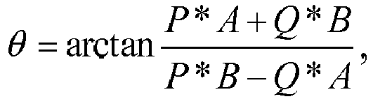
wherein the first amplitude parameter is obtained by a formula as follows:
wherein the second amplitude parameter is obtained by a formula as follows:
- The detecting method (400) of claim 2, further comprising:setting the first amplitude and the power angle of the first voltage signal; orthe detecting method further comprising:setting an active power signal and a reactive power signal; andgenerating the first amplitude and the power angle of the first voltage signal based on the active power signal and the reactive power signal.
- A detecting method (200) for detecting an output impedance angle of an inverter, comprising:controlling an inverter to output a second voltage signal and a current signal based on a first voltage signal, wherein the first voltage signal comprises a first amplitude and a power angle, a value of one of the first amplitude and the power angle is variable, and a value of the other one of the first amplitude and the power angle is constant;calculating a first active power, a second active power, a first reactive power, and a second reactive power based on the second voltage signal and the current signal; andcalculating an output impedance angle of the inverter based on a product of the first active power and a first amplitude parameter, a product of the first active power and a second amplitude parameter, a product of the second active power and the first amplitude parameter, and a product of the second active power and the second amplitude parameter, or calculating the output impedance angle of the inverter based on a product of the first reactive power and the first amplitude parameter, a product of the first reactive power and the second amplitude parameter, a product of the second reactive power and the first amplitude parameter, and a product of the second reactive power and the second amplitude parameter, wherein the first amplitude parameter corresponds to the first amplitude of the first voltage signal, and the second amplitude parameter corresponds to the first amplitude of the first voltage signal and a second amplitude of an AC voltage.
- The detecting method (500) of claim 4, wherein the first amplitude is a constant value, and the power angle changes from a first power angle to a second power angle, wherein a step of calculating the output impedance angle of the inverter comprises:calculating the output impedance angle of the inverter based on one of formulas as follows:


wherein the first parameter is obtained by a formula as follows:
wherein the second parameter is obtained by a formula as follows:
wherein the third parameter is obtained by a formula as follows:
wherein the fourth parameter is obtained by a formula as follows:
- The detecting method (500, 1000, 1100) of claim 4, further
comprising:setting the first amplitude of the first voltage signal; andsetting the power angle of the first voltage signal to change from the first power angle to the second power angle; orthe detecting method further comprising:setting an active power signal to be a constant value;setting a reactive power signal to change from a first reactive power signal to a second reactive power signal; andgenerating the first amplitude and the power angle of the first voltage signal based on the active power signal, the first reactive power signal, and the second reactive power signal; orthe detecting method further comprising:setting an active power signal to change from a first active power signal to a second active power signal;setting a reactive power signal to be a constant value; andgenerating the first amplitude and the power angle of the first voltage signal based on the first active power signal, the second active power signal, and the reactive power signal. - The detecting method (600) of claim 4, wherein the first amplitude changes from a first value to a second value, and the power angle is a constant value, wherein a step of calculating the output impedance angle of the inverter comprises:calculating the output impedance angle of the inverter based on one of formulas as follows:


wherein the first parameter is obtained by a formula as follows:
wherein the second parameter is obtained by a formula as follows:
wherein the third parameter is obtained by a formula as follows:
wherein the fourth parameter is obtained by a formula as follows:
- The detecting method (600, 1000, 1100) of claim 7, further comprising:setting the first amplitude of the first voltage signal to change from the first value to the second value; andsetting the power angle of the first voltage signal; orthe detecting method further comprising:setting an active power signal to be a constant value;setting a reactive power signal to change from a first reactive power signal to a second reactive power signal; andgenerating the first amplitude and the power angle of the first voltage signal based on the active power signal, the first reactive power signal, and the second reactive power signal; orthe detecting method further comprising:setting an active power signal to change from a first active power signal to a second active power signal;setting a reactive power signal to be a constant value; andgenerating the first amplitude and the power angle of the first voltage signal based on the first active power signal, the second active power signal, and the reactive power signal.
- A detecting device (100) for detecting an output impedance angle of an inverter (1500), comprising:a control unit (110) configured for controlling an inverter (1500) to output a second voltage signal and a current signal based on a first voltage signal;an active power and reactive power calculation unit (120) configured for calculating an active power and a reactive power based on the second voltage signal and the current signal; andan impedance angle calculation unit (130) configured for calculating an output impedance angle of the inverter (1500) based on a product of the active power and a first amplitude parameter, a product of the active power and a second amplitude parameter, a product of the reactive power and the first amplitude parameter, and a product of the reactive power and the second amplitude parameter, wherein the first amplitude parameter corresponds to a first amplitude of the first voltage signal, and the second amplitude parameter corresponds to the first amplitude of the first voltage signal and a second amplitude of an AC voltage.
- The detecting device (100) of claim 9, wherein the output impedance angle of the inverter (1500) is obtained by a formula as follows:

wherein the first amplitude parameter is obtained by a formula as follows:
wherein the second amplitude parameter is obtained by a formula as follows:
- The detecting device (100A) of claim 10, further comprising:a voltage signal setting unit (140) configured for setting the first amplitude and the power angle of the first voltage signal.
- The detecting device (100B) of claim 10, further comprising:a power setting unit (150) configured for setting an active power signal and a reactive power signal; anda voltage signal generating unit (140A) configured for generating the first amplitude and the power angle of the first voltage signal based on the active power signal and the reactive power signal.
- A detecting device (100) for detecting an output impedance angle of an inverter (1500), comprising:a control unit (110) configured for controlling an inverter (1500) to output a second voltage signal and a current signal based on a first voltage signal, wherein the first voltage signal comprises a first amplitude and a power angle, a value of one of the first amplitude and the power angle is variable, and a value of the other one of the first amplitude and the power angle is constant;an active power and reactive power calculation unit (120) configured for calculating a first active power, a second active power, a first reactive power, and a second reactive power based on the second voltage signal and the current signal; andan impedance angle calculation unit (130) configured for calculating an output impedance angle of the inverter (1500) based on a product of the first active power and a first amplitude parameter, a product of the first active power and a second amplitude parameter, a product of the second active power and the first amplitude parameter, and a product of the second active power and the second amplitude parameter, or calculating the output impedance angle of the inverter (1500) based on a product of the first reactive power and the first amplitude parameter, a product of the first reactive power and the second amplitude parameter, a product of the second reactive power and the first amplitude parameter, and a product of the second reactive power and the second amplitude parameter, wherein the first amplitude parameter corresponds to the first amplitude of the first voltage signal, and the second amplitude parameter corresponds to the first amplitude of the first voltage signal, and a second amplitude of an AC voltage.
- The detecting device (100) of claim 13, wherein the first amplitude is a constant value, and the power angle changes from a first power angle to a second power angle, wherein the output impedance angle of the inverter (1500) is obtained by one of formulas as follows:


wherein the first parameter is obtained by a formula as follows:
wherein Uc is the first amplitude, and δ1 is the first power angle; wherein the second parameter is obtained by a formula as follows: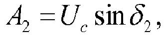
wherein the third parameter is obtained by a formula as follows:
wherein the fourth parameter is obtained by a formula as follows:
- The detecting device (100) of claim 13, wherein the first amplitude changes from a first value to a second value, and the power angle is a constant value, wherein the output impedance angle of the inverter (1500) is obtained by one of formulas as follows:
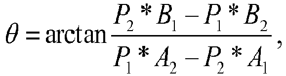

wherein the first parameter is obtained by a formula as follows:
wherein the second parameter is obtained by a formula as follows:
wherein the third parameter is obtained by a formula as follows:
wherein the fourth parameter is obtained by a formula as follows:
Applications Claiming Priority (1)
| Application Number | Priority Date | Filing Date | Title |
|---|---|---|---|
| CN201510274064.5A CN106291107B (en) | 2015-05-26 | 2015-05-26 | Device and method for detecting output impedance angle of inverter |
Publications (3)
| Publication Number | Publication Date |
|---|---|
| EP3098957A2 true EP3098957A2 (en) | 2016-11-30 |
| EP3098957A3 EP3098957A3 (en) | 2017-05-03 |
| EP3098957B1 EP3098957B1 (en) | 2022-08-31 |
Family
ID=56132735
Family Applications (1)
| Application Number | Title | Priority Date | Filing Date |
|---|---|---|---|
| EP16167628.3A Active EP3098957B1 (en) | 2015-05-26 | 2016-04-29 | Detecting device and detecting method for detecting output impedance angle of inverter |
Country Status (4)
| Country | Link |
|---|---|
| US (1) | US9772360B2 (en) |
| EP (1) | EP3098957B1 (en) |
| CN (1) | CN106291107B (en) |
| TW (1) | TWI588496B (en) |
Families Citing this family (2)
| Publication number | Priority date | Publication date | Assignee | Title |
|---|---|---|---|---|
| CN113346477B (en) * | 2021-05-08 | 2023-09-19 | 深圳市禾望电气股份有限公司 | Power grid parameter estimation method and system |
| CN115308527B (en) * | 2022-08-03 | 2026-01-20 | 华北电力科学研究院有限责任公司 | Impedance characteristic measurement method, circuit, device and system of flexible direct current transmission network |
Family Cites Families (10)
| Publication number | Priority date | Publication date | Assignee | Title |
|---|---|---|---|---|
| JPH0753036B2 (en) * | 1985-08-30 | 1995-06-05 | 三菱電機株式会社 | Parallel operation controller for AC output converter and commercial power supply |
| TW242203B (en) * | 1991-04-22 | 1995-03-01 | Mitsubishi Electric Machine | |
| JP2728575B2 (en) * | 1991-06-14 | 1998-03-18 | 株式会社日立製作所 | Power conversion method and device |
| US5351181A (en) * | 1993-03-12 | 1994-09-27 | Electric Power Research Institute, Inc. | Low cost active power line conditioner |
| EP1870993A1 (en) * | 2006-06-22 | 2007-12-26 | ALSTOM Technology Ltd | Method of controlling a three level converter |
| JP4931558B2 (en) | 2006-11-15 | 2012-05-16 | 栄 柴崎 | Switching power supply |
| CN101488664B (en) * | 2009-02-27 | 2011-06-15 | 上海航锐电源科技有限公司 | Anti-island effect protection method based on output current frequency disturbance |
| WO2013087085A1 (en) * | 2011-12-16 | 2013-06-20 | Fachhochschule Südwestfalen | Method for active control of frequency and voltage in a power supply grid with decentralized power supply systems |
| CN105634309B (en) * | 2014-11-06 | 2018-06-22 | 台达电子工业股份有限公司 | Control method and control device for inverter system |
| CN204334379U (en) * | 2014-12-12 | 2015-05-13 | 国家电网公司 | The V/f-with hysteretic characteristic falls down vertical microgrid inverter power supply |
-
2015
- 2015-05-26 CN CN201510274064.5A patent/CN106291107B/en active Active
- 2015-08-17 TW TW104126651A patent/TWI588496B/en active
-
2016
- 2016-03-30 US US15/084,492 patent/US9772360B2/en active Active
- 2016-04-29 EP EP16167628.3A patent/EP3098957B1/en active Active
Non-Patent Citations (1)
| Title |
|---|
| None |
Also Published As
| Publication number | Publication date |
|---|---|
| EP3098957A3 (en) | 2017-05-03 |
| US9772360B2 (en) | 2017-09-26 |
| TW201641943A (en) | 2016-12-01 |
| CN106291107B (en) | 2019-08-23 |
| CN106291107A (en) | 2017-01-04 |
| EP3098957B1 (en) | 2022-08-31 |
| US20160349298A1 (en) | 2016-12-01 |
| TWI588496B (en) | 2017-06-21 |
Similar Documents
| Publication | Publication Date | Title |
|---|---|---|
| Hu et al. | Decentralised control for reactive power sharing using adaptive virtual impedance | |
| EP2357721A1 (en) | Power conversion device | |
| DE112014007062T5 (en) | DRIVE AND CONTROL DEVICE FOR MULTILING MOTOR | |
| US9705419B2 (en) | Control signal generating system and inverter control device thereof for improving grid stability | |
| CN107782983B (en) | Method for detecting output phase loss of servo driver | |
| US11600467B2 (en) | Power supply devices for plasma systems and method of use | |
| WO2016065087A1 (en) | Systems and methods for controlling multi-level diode-clamped inverters using space vector pulse width modulation (svpwm) | |
| DE112017003818T5 (en) | Electrical power units with automatically set input voltage connection configuration | |
| EP3098930B1 (en) | Detecting device and detecting method for detecting output impedance angle of inverter | |
| DE102018205192A1 (en) | Control device for an electric motor | |
| CA1129494A (en) | Sliding notch pulse width modulation (pwm) | |
| DE112018007041B4 (en) | Control device for an electric motor and method for detecting a cable disconnection | |
| EP3098957B1 (en) | Detecting device and detecting method for detecting output impedance angle of inverter | |
| US9018871B2 (en) | Power conversion apparatus | |
| CN112492892B (en) | Power conversion device | |
| DE112021006077T5 (en) | ENERGY CONVERSION DEVICE | |
| CN106921323A (en) | Equipment, method and computer program for providing the adjustable parameter for phase-group | |
| DE102019114480A1 (en) | Motor control device, control method and program | |
| DE102012204058A1 (en) | CONTROL METHOD AND CONTROL DEVICE OF AN ENGINE INVERTER | |
| DE102015224586A1 (en) | Operating point determination of a synchronous machine | |
| DE102017204106A1 (en) | Method and device for operating a polyphase inverter | |
| DE19813363A1 (en) | Procedure for the indirect determination of the output voltage of a two-point inverter | |
| Farokhnia et al. | Fast closed‐form solution of line‐to‐line voltage total harmonic distortion for three‐level inverters | |
| DE102019114482A1 (en) | Motor control device, control method and program | |
| KR102046920B1 (en) | Apparattus for monitoring of power system |
Legal Events
| Date | Code | Title | Description |
|---|---|---|---|
| PUAI | Public reference made under article 153(3) epc to a published international application that has entered the european phase |
Free format text: ORIGINAL CODE: 0009012 |
|
| AK | Designated contracting states |
Kind code of ref document: A2 Designated state(s): AL AT BE BG CH CY CZ DE DK EE ES FI FR GB GR HR HU IE IS IT LI LT LU LV MC MK MT NL NO PL PT RO RS SE SI SK SM TR |
|
| AX | Request for extension of the european patent |
Extension state: BA ME |
|
| RIC1 | Information provided on ipc code assigned before grant |
Ipc: H02M 7/5387 20070101ALI20161202BHEP Ipc: H02M 7/00 20060101AFI20161202BHEP Ipc: H02J 3/38 20060101ALI20161202BHEP |
|
| PUAL | Search report despatched |
Free format text: ORIGINAL CODE: 0009013 |
|
| AK | Designated contracting states |
Kind code of ref document: A3 Designated state(s): AL AT BE BG CH CY CZ DE DK EE ES FI FR GB GR HR HU IE IS IT LI LT LU LV MC MK MT NL NO PL PT RO RS SE SI SK SM TR |
|
| AX | Request for extension of the european patent |
Extension state: BA ME |
|
| RIC1 | Information provided on ipc code assigned before grant |
Ipc: H02M 7/00 20060101AFI20170327BHEP Ipc: H02J 3/38 20060101ALI20170327BHEP Ipc: H02M 7/5387 20070101ALI20170327BHEP |
|
| STAA | Information on the status of an ep patent application or granted ep patent |
Free format text: STATUS: REQUEST FOR EXAMINATION WAS MADE |
|
| 17P | Request for examination filed |
Effective date: 20171102 |
|
| RBV | Designated contracting states (corrected) |
Designated state(s): AL AT BE BG CH CY CZ DE DK EE ES FI FR GB GR HR HU IE IS IT LI LT LU LV MC MK MT NL NO PL PT RO RS SE SI SK SM TR |
|
| STAA | Information on the status of an ep patent application or granted ep patent |
Free format text: STATUS: EXAMINATION IS IN PROGRESS |
|
| 17Q | First examination report despatched |
Effective date: 20191119 |
|
| REG | Reference to a national code |
Ref country code: DE Ref legal event code: R079 Ref document number: 602016074602 Country of ref document: DE Free format text: PREVIOUS MAIN CLASS: H02M0007000000 Ipc: H02M0007538700 |
|
| GRAP | Despatch of communication of intention to grant a patent |
Free format text: ORIGINAL CODE: EPIDOSNIGR1 |
|
| STAA | Information on the status of an ep patent application or granted ep patent |
Free format text: STATUS: GRANT OF PATENT IS INTENDED |
|
| RIC1 | Information provided on ipc code assigned before grant |
Ipc: H02M 1/00 20060101ALN20220421BHEP Ipc: H02M 7/5387 20070101AFI20220421BHEP |
|
| INTG | Intention to grant announced |
Effective date: 20220518 |
|
| GRAS | Grant fee paid |
Free format text: ORIGINAL CODE: EPIDOSNIGR3 |
|
| GRAA | (expected) grant |
Free format text: ORIGINAL CODE: 0009210 |
|
| STAA | Information on the status of an ep patent application or granted ep patent |
Free format text: STATUS: THE PATENT HAS BEEN GRANTED |
|
| AK | Designated contracting states |
Kind code of ref document: B1 Designated state(s): AL AT BE BG CH CY CZ DE DK EE ES FI FR GB GR HR HU IE IS IT LI LT LU LV MC MK MT NL NO PL PT RO RS SE SI SK SM TR |
|
| REG | Reference to a national code |
Ref country code: CH Ref legal event code: EP Ref country code: GB Ref legal event code: FG4D |
|
| REG | Reference to a national code |
Ref country code: AT Ref legal event code: REF Ref document number: 1516045 Country of ref document: AT Kind code of ref document: T Effective date: 20220915 Ref country code: DE Ref legal event code: R096 Ref document number: 602016074602 Country of ref document: DE |
|
| REG | Reference to a national code |
Ref country code: IE Ref legal event code: FG4D |
|
| REG | Reference to a national code |
Ref country code: LT Ref legal event code: MG9D |
|
| REG | Reference to a national code |
Ref country code: NL Ref legal event code: MP Effective date: 20220831 |
|
| PG25 | Lapsed in a contracting state [announced via postgrant information from national office to epo] |
Ref country code: SE Free format text: LAPSE BECAUSE OF FAILURE TO SUBMIT A TRANSLATION OF THE DESCRIPTION OR TO PAY THE FEE WITHIN THE PRESCRIBED TIME-LIMIT Effective date: 20220831 Ref country code: RS Free format text: LAPSE BECAUSE OF FAILURE TO SUBMIT A TRANSLATION OF THE DESCRIPTION OR TO PAY THE FEE WITHIN THE PRESCRIBED TIME-LIMIT Effective date: 20220831 Ref country code: NO Free format text: LAPSE BECAUSE OF FAILURE TO SUBMIT A TRANSLATION OF THE DESCRIPTION OR TO PAY THE FEE WITHIN THE PRESCRIBED TIME-LIMIT Effective date: 20221130 Ref country code: LV Free format text: LAPSE BECAUSE OF FAILURE TO SUBMIT A TRANSLATION OF THE DESCRIPTION OR TO PAY THE FEE WITHIN THE PRESCRIBED TIME-LIMIT Effective date: 20220831 Ref country code: LT Free format text: LAPSE BECAUSE OF FAILURE TO SUBMIT A TRANSLATION OF THE DESCRIPTION OR TO PAY THE FEE WITHIN THE PRESCRIBED TIME-LIMIT Effective date: 20220831 Ref country code: FI Free format text: LAPSE BECAUSE OF FAILURE TO SUBMIT A TRANSLATION OF THE DESCRIPTION OR TO PAY THE FEE WITHIN THE PRESCRIBED TIME-LIMIT Effective date: 20220831 Ref country code: ES Free format text: LAPSE BECAUSE OF FAILURE TO SUBMIT A TRANSLATION OF THE DESCRIPTION OR TO PAY THE FEE WITHIN THE PRESCRIBED TIME-LIMIT Effective date: 20220831 |
|
| REG | Reference to a national code |
Ref country code: AT Ref legal event code: MK05 Ref document number: 1516045 Country of ref document: AT Kind code of ref document: T Effective date: 20220831 |
|
| PG25 | Lapsed in a contracting state [announced via postgrant information from national office to epo] |
Ref country code: PL Free format text: LAPSE BECAUSE OF FAILURE TO SUBMIT A TRANSLATION OF THE DESCRIPTION OR TO PAY THE FEE WITHIN THE PRESCRIBED TIME-LIMIT Effective date: 20220831 Ref country code: IS Free format text: LAPSE BECAUSE OF FAILURE TO SUBMIT A TRANSLATION OF THE DESCRIPTION OR TO PAY THE FEE WITHIN THE PRESCRIBED TIME-LIMIT Effective date: 20221231 Ref country code: HR Free format text: LAPSE BECAUSE OF FAILURE TO SUBMIT A TRANSLATION OF THE DESCRIPTION OR TO PAY THE FEE WITHIN THE PRESCRIBED TIME-LIMIT Effective date: 20220831 Ref country code: GR Free format text: LAPSE BECAUSE OF FAILURE TO SUBMIT A TRANSLATION OF THE DESCRIPTION OR TO PAY THE FEE WITHIN THE PRESCRIBED TIME-LIMIT Effective date: 20221201 |
|
| PG25 | Lapsed in a contracting state [announced via postgrant information from national office to epo] |
Ref country code: SM Free format text: LAPSE BECAUSE OF FAILURE TO SUBMIT A TRANSLATION OF THE DESCRIPTION OR TO PAY THE FEE WITHIN THE PRESCRIBED TIME-LIMIT Effective date: 20220831 Ref country code: RO Free format text: LAPSE BECAUSE OF FAILURE TO SUBMIT A TRANSLATION OF THE DESCRIPTION OR TO PAY THE FEE WITHIN THE PRESCRIBED TIME-LIMIT Effective date: 20220831 Ref country code: PT Free format text: LAPSE BECAUSE OF FAILURE TO SUBMIT A TRANSLATION OF THE DESCRIPTION OR TO PAY THE FEE WITHIN THE PRESCRIBED TIME-LIMIT Effective date: 20230102 Ref country code: DK Free format text: LAPSE BECAUSE OF FAILURE TO SUBMIT A TRANSLATION OF THE DESCRIPTION OR TO PAY THE FEE WITHIN THE PRESCRIBED TIME-LIMIT Effective date: 20220831 Ref country code: CZ Free format text: LAPSE BECAUSE OF FAILURE TO SUBMIT A TRANSLATION OF THE DESCRIPTION OR TO PAY THE FEE WITHIN THE PRESCRIBED TIME-LIMIT Effective date: 20220831 Ref country code: AT Free format text: LAPSE BECAUSE OF FAILURE TO SUBMIT A TRANSLATION OF THE DESCRIPTION OR TO PAY THE FEE WITHIN THE PRESCRIBED TIME-LIMIT Effective date: 20220831 |
|
| PG25 | Lapsed in a contracting state [announced via postgrant information from national office to epo] |
Ref country code: SK Free format text: LAPSE BECAUSE OF FAILURE TO SUBMIT A TRANSLATION OF THE DESCRIPTION OR TO PAY THE FEE WITHIN THE PRESCRIBED TIME-LIMIT Effective date: 20220831 Ref country code: EE Free format text: LAPSE BECAUSE OF FAILURE TO SUBMIT A TRANSLATION OF THE DESCRIPTION OR TO PAY THE FEE WITHIN THE PRESCRIBED TIME-LIMIT Effective date: 20220831 |
|
| REG | Reference to a national code |
Ref country code: DE Ref legal event code: R097 Ref document number: 602016074602 Country of ref document: DE |
|
| PG25 | Lapsed in a contracting state [announced via postgrant information from national office to epo] |
Ref country code: NL Free format text: LAPSE BECAUSE OF FAILURE TO SUBMIT A TRANSLATION OF THE DESCRIPTION OR TO PAY THE FEE WITHIN THE PRESCRIBED TIME-LIMIT Effective date: 20220831 Ref country code: AL Free format text: LAPSE BECAUSE OF FAILURE TO SUBMIT A TRANSLATION OF THE DESCRIPTION OR TO PAY THE FEE WITHIN THE PRESCRIBED TIME-LIMIT Effective date: 20220831 |
|
| PLBE | No opposition filed within time limit |
Free format text: ORIGINAL CODE: 0009261 |
|
| STAA | Information on the status of an ep patent application or granted ep patent |
Free format text: STATUS: NO OPPOSITION FILED WITHIN TIME LIMIT |
|
| 26N | No opposition filed |
Effective date: 20230601 |
|
| PG25 | Lapsed in a contracting state [announced via postgrant information from national office to epo] |
Ref country code: SI Free format text: LAPSE BECAUSE OF FAILURE TO SUBMIT A TRANSLATION OF THE DESCRIPTION OR TO PAY THE FEE WITHIN THE PRESCRIBED TIME-LIMIT Effective date: 20220831 |
|
| REG | Reference to a national code |
Ref country code: CH Ref legal event code: PL |
|
| GBPC | Gb: european patent ceased through non-payment of renewal fee |
Effective date: 20230429 |
|
| PG25 | Lapsed in a contracting state [announced via postgrant information from national office to epo] |
Ref country code: LU Free format text: LAPSE BECAUSE OF NON-PAYMENT OF DUE FEES Effective date: 20230429 |
|
| REG | Reference to a national code |
Ref country code: BE Ref legal event code: MM Effective date: 20230430 |
|
| PG25 | Lapsed in a contracting state [announced via postgrant information from national office to epo] |
Ref country code: MC Free format text: LAPSE BECAUSE OF FAILURE TO SUBMIT A TRANSLATION OF THE DESCRIPTION OR TO PAY THE FEE WITHIN THE PRESCRIBED TIME-LIMIT Effective date: 20220831 |
|
| PG25 | Lapsed in a contracting state [announced via postgrant information from national office to epo] |
Ref country code: GB Free format text: LAPSE BECAUSE OF NON-PAYMENT OF DUE FEES Effective date: 20230429 |
|
| PG25 | Lapsed in a contracting state [announced via postgrant information from national office to epo] |
Ref country code: MC Free format text: LAPSE BECAUSE OF FAILURE TO SUBMIT A TRANSLATION OF THE DESCRIPTION OR TO PAY THE FEE WITHIN THE PRESCRIBED TIME-LIMIT Effective date: 20220831 Ref country code: LI Free format text: LAPSE BECAUSE OF NON-PAYMENT OF DUE FEES Effective date: 20230430 Ref country code: GB Free format text: LAPSE BECAUSE OF NON-PAYMENT OF DUE FEES Effective date: 20230429 Ref country code: FR Free format text: LAPSE BECAUSE OF NON-PAYMENT OF DUE FEES Effective date: 20230430 Ref country code: CH Free format text: LAPSE BECAUSE OF NON-PAYMENT OF DUE FEES Effective date: 20230430 |
|
| REG | Reference to a national code |
Ref country code: IE Ref legal event code: MM4A |
|
| PG25 | Lapsed in a contracting state [announced via postgrant information from national office to epo] |
Ref country code: BE Free format text: LAPSE BECAUSE OF NON-PAYMENT OF DUE FEES Effective date: 20230430 |
|
| PG25 | Lapsed in a contracting state [announced via postgrant information from national office to epo] |
Ref country code: IE Free format text: LAPSE BECAUSE OF NON-PAYMENT OF DUE FEES Effective date: 20230429 |
|
| PG25 | Lapsed in a contracting state [announced via postgrant information from national office to epo] |
Ref country code: IE Free format text: LAPSE BECAUSE OF NON-PAYMENT OF DUE FEES Effective date: 20230429 |
|
| PG25 | Lapsed in a contracting state [announced via postgrant information from national office to epo] |
Ref country code: IT Free format text: LAPSE BECAUSE OF FAILURE TO SUBMIT A TRANSLATION OF THE DESCRIPTION OR TO PAY THE FEE WITHIN THE PRESCRIBED TIME-LIMIT Effective date: 20220831 |
|
| PG25 | Lapsed in a contracting state [announced via postgrant information from national office to epo] |
Ref country code: BG Free format text: LAPSE BECAUSE OF FAILURE TO SUBMIT A TRANSLATION OF THE DESCRIPTION OR TO PAY THE FEE WITHIN THE PRESCRIBED TIME-LIMIT Effective date: 20220831 |
|
| PG25 | Lapsed in a contracting state [announced via postgrant information from national office to epo] |
Ref country code: BG Free format text: LAPSE BECAUSE OF FAILURE TO SUBMIT A TRANSLATION OF THE DESCRIPTION OR TO PAY THE FEE WITHIN THE PRESCRIBED TIME-LIMIT Effective date: 20220831 |
|
| PGFP | Annual fee paid to national office [announced via postgrant information from national office to epo] |
Ref country code: DE Payment date: 20250305 Year of fee payment: 10 |
|
| PG25 | Lapsed in a contracting state [announced via postgrant information from national office to epo] |
Ref country code: CY Free format text: LAPSE BECAUSE OF FAILURE TO SUBMIT A TRANSLATION OF THE DESCRIPTION OR TO PAY THE FEE WITHIN THE PRESCRIBED TIME-LIMIT; INVALID AB INITIO Effective date: 20160429 |
|
| PG25 | Lapsed in a contracting state [announced via postgrant information from national office to epo] |
Ref country code: HU Free format text: LAPSE BECAUSE OF FAILURE TO SUBMIT A TRANSLATION OF THE DESCRIPTION OR TO PAY THE FEE WITHIN THE PRESCRIBED TIME-LIMIT; INVALID AB INITIO Effective date: 20160429 |
|
| PG25 | Lapsed in a contracting state [announced via postgrant information from national office to epo] |
Ref country code: TR Free format text: LAPSE BECAUSE OF FAILURE TO SUBMIT A TRANSLATION OF THE DESCRIPTION OR TO PAY THE FEE WITHIN THE PRESCRIBED TIME-LIMIT Effective date: 20220831 |