EP3098672A1 - Konfigurationsvorrichtung und verfahren zum konfigurieren eines automatisierungssystems - Google Patents
Konfigurationsvorrichtung und verfahren zum konfigurieren eines automatisierungssystems Download PDFInfo
- Publication number
- EP3098672A1 EP3098672A1 EP15169423.9A EP15169423A EP3098672A1 EP 3098672 A1 EP3098672 A1 EP 3098672A1 EP 15169423 A EP15169423 A EP 15169423A EP 3098672 A1 EP3098672 A1 EP 3098672A1
- Authority
- EP
- European Patent Office
- Prior art keywords
- data
- customer
- user data
- software tool
- configuration
- Prior art date
- Legal status (The legal status is an assumption and is not a legal conclusion. Google has not performed a legal analysis and makes no representation as to the accuracy of the status listed.)
- Granted
Links
Images

Classifications
-
- G—PHYSICS
- G05—CONTROLLING; REGULATING
- G05B—CONTROL OR REGULATING SYSTEMS IN GENERAL; FUNCTIONAL ELEMENTS OF SUCH SYSTEMS; MONITORING OR TESTING ARRANGEMENTS FOR SUCH SYSTEMS OR ELEMENTS
- G05B11/00—Automatic controllers
- G05B11/01—Automatic controllers electric
- G05B11/011—Automatic controllers electric details of the correcting means
-
- G—PHYSICS
- G05—CONTROLLING; REGULATING
- G05B—CONTROL OR REGULATING SYSTEMS IN GENERAL; FUNCTIONAL ELEMENTS OF SUCH SYSTEMS; MONITORING OR TESTING ARRANGEMENTS FOR SUCH SYSTEMS OR ELEMENTS
- G05B19/00—Program-control systems
- G05B19/02—Program-control systems electric
- G05B19/04—Program control other than numerical control, i.e. in sequence controllers or logic controllers
- G05B19/042—Program control other than numerical control, i.e. in sequence controllers or logic controllers using digital processors
- G05B19/0426—Programming the control sequence
-
- G—PHYSICS
- G06—COMPUTING OR CALCULATING; COUNTING
- G06F—ELECTRIC DIGITAL DATA PROCESSING
- G06F8/00—Arrangements for software engineering
- G06F8/70—Software maintenance or management
-
- G—PHYSICS
- G05—CONTROLLING; REGULATING
- G05B—CONTROL OR REGULATING SYSTEMS IN GENERAL; FUNCTIONAL ELEMENTS OF SUCH SYSTEMS; MONITORING OR TESTING ARRANGEMENTS FOR SUCH SYSTEMS OR ELEMENTS
- G05B2219/00—Program-control systems
- G05B2219/10—Plc systems
- G05B2219/15—Plc structure of the system
- G05B2219/15011—Configuration of operating system
-
- G—PHYSICS
- G05—CONTROLLING; REGULATING
- G05B—CONTROL OR REGULATING SYSTEMS IN GENERAL; FUNCTIONAL ELEMENTS OF SUCH SYSTEMS; MONITORING OR TESTING ARRANGEMENTS FOR SUCH SYSTEMS OR ELEMENTS
- G05B2219/00—Program-control systems
- G05B2219/30—Nc systems
- G05B2219/35—Nc in input of data, input till input file format
- G05B2219/35412—Special interface for manual input to pc
Definitions
- the invention relates to a configuration device and a method for configuring a customer's automation system comprising device components of one or more manufacturers / manufacturers.
- a customer may configure a device component of a manufacturer via a computer-based software tool such that the device component has a corresponding behavior for operation with a customer's work machine.
- the customer often has to transfer his knowledge from his special point of view for the application of his work machine to the general function of the device component. This often includes the consideration of the terms or terminology of the physical units used or the conversion rules.
- the z. B. wants to configure an automation system with multiple device components, as he must go through all the queries again and again to enter his user data for all device components using the manufacturer software tools.
- the customer When changing the user data, such. B. a modification of the work machine, the customer must update all data in the device components, d. H. reenter in all wizards.
- the automation system comprises several device components from different manufacturers, there is the additional problem of the customer to work with different software tools for the various device components, or to be familiar with the various software tools.
- automation systems are known in which the work machine and the device component are connected via a bus system with a higher-level programmable safety controller, a so-called PLC.
- PLC programmable safety controller
- all the configuration data of the automation system can be stored in the PLC, so that the PLC communicates the configuration data of the work machine and the device components via the bus system to the work machine and to the device components, the configuration data being determined according to user data from the PLC.
- the disadvantage for the customer arises that a corresponding knowledge regarding the operation or the programming of the PLC is required. Further, even if the configuration data is stored in the PLC, the customer must update all user data on the device components to update the configuration data for storage in the PLC accordingly.
- a configuration device for configuring an automation system of a customer, the device components one or more manufacturers / manufacturers, with at least a first software tool, in particular with a first user interface, which is provided for inputting user data in customer-specific terminology and stores the input user data in a data management area, with a second software tool, in particular with a second user interface, is provided for receiving the user data and has a calculation unit for determining configuration data from the user data, wherein the second software tool has at least one mapping rule that prepares the user data stored in customer-specific terminology for the calculation unit in manufacturer-specific terminologies, and wherein a processing of the user data and a storage of the configuration data by the second software tool separately from the data management area of the first software tool are feasible.
- the first and second software tools each comprise at least one input mask, wherein the input mask of the first software tool for the terminology of the customer and the input mask of the second software tool for the terminology of the manufacturer are formed.
- the input masks are formed, various applications, eg. As machine types and / or applications, the customer.
- the custom terminology includes a first data format in which the customer describes the user data.
- the user data can be assigned to the data management area of the first software tool.
- the user data comprises automation system operating data, preferably loading data, movement speed, movement profile or the like of the automation system.
- the manufacturer-specific terminology comprises a second data format in which the manufacturer describes the configuration data.
- the configuration data includes component operating data, preferably acceleration ramps, deceleration ramps, scan range, response times or the like of the device components.
- the mapping rule of the second software tool has a translation algorithm which converts the customer-specific terminological user data into manufacturer-specific terminological data and makes it available to the calculation unit.
- the customer-specific terminological user data can be assigned from the data management area of the first software tool by means of drag and drop of the mapping rule of the second software tool.
- the object is further achieved according to the invention by a method for configuring a customer's automation system, comprising device components of one or more manufacturers / manufacturers, with the steps of inputting and storing user data in customer-specific terminologies in a data management area by means of a first software tool, linking the in customer-specific Terminology stored user data with at least one mapping rule of a second software tool, converting the customer-specific terminology of the user data by the mapping rule in manufacturer-specific terminologies, creating from the converted user-specific terminology user data configuration data by means of a calculation unit, and providing the manufacturer-specific terminological configuration data of the respective device components of the automation system in one additional data management area.
- the user data is entered in custom terminologies by means of the first software tool. Furthermore, according to a preferred embodiment, the conversion of the customer-specific terminological user data into manufacturer-specific terminologies and the production of the manufacturer-specific terminological configuration data are carried out in the second software tool.
- the customer-specific terminological user data are linked by drag & drop from the first software tool to the second software tool.
- FIG. 1 a preferred embodiment of the invention is described schematically, in which a customer wants to configure a work machine in the form of a driverless transport vehicle, a so-called "Automatic Guided Vehicle” AGV.
- the driverless transport vehicle AGV is provided in the illustrated preferred embodiment for transporting loads L, wherein the loads L may have different dimensions and weights. According to the loads L to be transported, the driving behavior of the driverless transport vehicle AGV is adjusted.
- the driverless transport vehicle AGV has a computer unit CPU, which monitors and controls the driverless transport vehicle AGV. Data for monitoring and controlling the driverless transport vehicle AGV provide signals from device components 1, 2 of one manufacturer or several manufacturers, which are arranged on the driverless transport vehicle AGV.
- the driverless transport vehicle AGV, the computer unit CPU and the device components 1, 2 form the customer's automation system, which the customer configures with a configuration device KV according to the invention.
- the mentioned adapted driving behavior and the mentioned loads L to be transported are known to the customer as user data AD1, AD2, AD3 described in more detail below.
- the configuration device KV according to the invention has a first software tool S1.1, S1.2, S1.3 and a second software tool S2.1, S2.2.
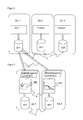
- FIGS. 2 and 3 the configuration device KV according to the invention is shown in detail.
- FIG. 2 shows three first software tool S1.1, S1.2, S1.3 of the configuration device KV according to the invention.
- the first three software tools S1.1, S1.2, S1.3 each include a user interface that maps various applications of the customer in his customer-specific terminology.
- the first user interface depicts the application of the driverless transport vehicle AGV.
- the second user interface depicts the application of a press, and the third user interface depicts the application of a robot.
- the customer can enter his user data AD1-AD3 in customer-specific terminologies, the entered user data AD1-AD3 being stored in a data management area 3.
- the data management area 3 may also consist of a non-volatile data memory.
- Customer-specific terminology refers to a first data format in which the customer describes his user data. Ie. the customer gives his transportable Loads L, for example, under the name “number of boxes” with the weight unit “kilograms per box” or the desired motion profile of his driverless transport vehicle AGV under “profile i” and with the speed unit "m / s" in the user interface of the first software tool S1.1 of inventive configuration device KV.
- the user data therefore include operating data of its automation system, hereinafter also referred to as automation system operating data, which may be, for example, load data, movement speed, movement profile or the like of the driverless transport vehicle AGV.
- automation system operating data may be, for example, load data, movement speed, movement profile or the like of the driverless transport vehicle AGV.
- the customer thus has the advantage that he can enter his user data AD1 - AD3 in his usual terminology and in the usual data format in the inventive configuration device KV.
- second software tool S2.1, S2.2 which are provided for receiving the stored user data AD1 and are each provided with a calculation unit 4 for determining configuration data KD1, KD2 from the user data AD1.
- the second software tool S2.1, S2.2 also advantageously each comprise a user interface which is designed for the terminology of the manufacturer or the manufacturer of the device components 1, 2.
- the manufacturer-specific terminology here comprises a second data format in which the manufacturer or the manufacturer describes / describes the configuration data KD1, KD2.
- the configuration data KD1, KD2 comprise operating data of the device components 1, 2, also referred to below as component operating data, the component operating data preferably including acceleration ramps, braking ramps BR, scanning range SB, reaction times or the like of the device components 1, 2.
- the second software tools S2.1, S2.2 each have at least one mapping rule AV1, AV2 which stores the user data AD1 stored in customer-specific terminology for the calculation unit 4 of the second software tools S2.1, S2.2 in FIG prepared by manufacturer-specific terminology.
- the linking of the user data AD1 to the respective mapping specifications AV1, AV2 is illustrated by the arrows 6. Ie. the respective mapping rule AV1, AV2 adapts the first data format of the user data AD1 to the second data format for the calculation unit 4 of the second software tool S2.2, S2.2, so that the stored user data AD1 can be used by the calculation unit 4.
- the respective second software tool S2.1, S2.2 preferably has a translation algorithm for this, which converts the customer-specific terminological user data AD1-AD3 into manufacturer-specific terminological data and makes it available to the calculation unit 4. From this, the calculation unit 4 of the respective second software tool S2.1, S2.2 generates the configuration data KD1, KD2 for the device components 1, 2 of the driverless transport vehicle AGV.
- the configuration data KD1, KD2 generated by the calculation unit 4 are stored in a further data management area 5 and made available to the customer.
- the data management areas 3, 5 of the first and second software tools S1, S2 are separated from one another so that preferably the customer-specific terminological user data AD1-AD3 from the data management area 3 are linked with the mapping rule AV1, AV2 of the second software tool S2 by means of drag and drop.
- the customer enters his user data AD1 in customer-specific terminology by means of the first software tool S1 in the data management area 3.
- the user data AD1 concerning the number of boxes transported and the loading of the driverless transport vehicle AGV in kilograms are stored in the data management area 3 in this customer-specific terminology.
- the user data AD1 stored in customer-specific terminology are preferably linked by means of drag-and-drop with the mapping rule AV1, AV2 of the second software tool S2.1, S2.2, where the customer-specific terminological user data AD1 is converted into manufacturer-specific terminological data.
- the configuration data KD1, KD2 for the device components 1, 2 are created by means of the calculation unit 4 of the second software tool S2.1, S2.2, the configuration data KD1, KD2, for example, the scan area SB of the device component 1 and the brake ramps BR of the device component 2 corresponding to the number of boxes and the weight of the load for the driverless transport vehicle AGV.
- the created configuration data KD1, KD2 for the device components 1, 2 are stored by the second software tool S2.1, S2.2 in the further data management area 5 and made available to the device components 1, 2.
- the customer can configure his automation system, in particular the driverless transport vehicle AGV, with the device components 1, 2, without knowledge of the manufacturer-specific terminology for the configuration data.
- the customer advantageously requires only a single input of his custom terminological user data in the configuration device KV according to the invention, so that the customer can save a lot of time in the multiple configuration.
- the described user interfaces of the first and second software tools S1.1-S1.3, S2.1-S2.2 can be combined in a single user interface, wherein the described functionalities of the two software tools S1.1-S1.3, S2.1 - S2.2 remain separated from each other.
- the configuration device KV allows an offline configuration of the automation system, so that after a completed configuration, the configuration data KD1, KD2 can be transmitted to the computer unit CPU of the driverless transport vehicle AGV.
- the second software tool S2.1, S2.2 preferably recognizes when the user data AD1-AD3 in the linked data management area 3 of the first software tool S1.1-S1.3 has changed, so that the second software tool S2.1, S2.2 the configuration data KD1, KD2 in the associated additional data management area 5 adapts.
- the adaptation can advantageously be made either automatically or after confirmation by the customer.
- new versions of the second software tool S2.1, S2.2, in the z. B. new calculation units 4 are implemented, establish a link to the stored in the management area 3 of the first software tool S1.1 - S1.3 user data AD1 - AD3, so that the customer does not need to re-enter its user data AD1 - AD3.
- further second software tools S2.i can be added, which are assigned to existing user data AD1-AD3. If z. B. the automation system is extended by another device.
Landscapes
- Engineering & Computer Science (AREA)
- Physics & Mathematics (AREA)
- General Physics & Mathematics (AREA)
- Automation & Control Theory (AREA)
- Software Systems (AREA)
- General Engineering & Computer Science (AREA)
- Theoretical Computer Science (AREA)
- Stored Programmes (AREA)
Abstract
Description
- Die Erfindung betrifft eine Konfigurationsvorrichtung und ein Verfahren zum Konfigurieren eines Automatisierungssystems eines Kunden, das Gerätekomponenten eines oder mehrerer Herstellers/Hersteller umfasst.
- Herkömmlich kann in der Automatisierungsindustrie ein Kunde über ein computerbasiertes Softwaretool eine Gerätekomponente eines Herstellers derart konfigurieren, so dass die Gerätekomponente ein entsprechendes Verhalten für einen Betrieb mit einer Arbeitsmaschine des Kunden aufweist.
- Hierzu muss der Kunde sein Wissen häufig aus seiner speziellen Sichtweise für die Anwendung seiner Arbeitsmaschine auf die allgemeine Funktion der Gerätekomponente transferieren. Dies schließt häufig auch die Überlegung bzgl. der verwendeten Begriffe bzw. Terminologie der physikalischen Einheiten oder den Umrechnungsregeln ein.
- Um die Konfiguration der Gerätekomponente bzw. die Übertragung von Anwenderdaten der Arbeitsmaschine auf die Gerätekomponente für den Kunden zu erleichtern, bieten einige Softwaretools Funktionen, sogenannte Assistenten an, die den Kunden anhand per schrittweiser Abfrage der Anwenderdaten durch die Einstellmöglichkeiten der Gerätekomponente leiten, so dass die Konfiguration des Automatisierungssystems für den Kunden erleichtert wird.
- Hierbei ergibt sich jedoch ein weiterer Nachteil für den Kunden, der z. B. ein Automatisierungssystem mit mehreren Gerätekomponenten konfigurieren möchte, da er die gesamten Abfragen immer wieder durchgehen muss, um seine Anwenderdaten für alle Gerätekomponente mittels des Herstellers Softwaretools einzugeben. Bei einer Änderung der Anwenderdaten, wie z. B. eine Modifikation der Arbeitsmaschine, muss der Kunde sämtliche Daten bei den Gerätekomponenten aktualisieren, d. h. in sämtlichen Assistenten erneut eingeben.
- Im Falle, dass das Automatisierungssystem mehrere Gerätekomponenten verschiedener Hersteller umfasst, besteht das zusätzliche Problem des Kunden, mit verschiedenen Softwaretools für die verschiedenen Gerätekomponenten zu arbeiten, bzw. sich mit den verschiedenen Softwaretools auszukennen.
- Ferner sind Automatisierungssysteme bekannt, bei denen die Arbeitsmaschine und die Gerätekomponente über ein Bussystem mit einer übergeordneten programmierbaren Sicherheitssteuerung, einer sogenannten SPS, verbunden sind. Hierbei können sämtliche Konfigurationsdaten des Automatisierungssystems in der SPS gespeichert sein, so dass die SPS die Konfigurationsdaten der Arbeitsmaschine und der Gerätekomponenten über das Bussystem an die Arbeitsmaschine und an die Gerätekomponenten kommuniziert, wobei die Konfigurationsdaten entsprechend Anwenderdaten von der SPS bestimmt werden.
- Auch in diesem Fall ergibt sich der Nachteil für den Kunden, dass eine entsprechende Kenntnis bzgl. der Bedienung bzw. der Programmierung der SPS vorausgesetzt wird. Ferner, auch wenn die Speicherung der Konfigurationsdaten in der SPS erfolgt, muss der Kunde sämtliche Anwenderdaten bei den Gerätekomponenten aktualisieren, um die Konfigurationsdaten zur Ablage in der SPS entsprechend zu aktualisieren.
- Es ist daher eine Aufgabe der Erfindung, eine Konfigurationsvorrichtung und ein Verfahren zum Konfigurieren eines Automatisierungssystems derart zu verbessern, dass die Konfiguration für den Kunden vereinfacht wird.
- Die Aufgabe wird erfindungsgemäß durch eine Konfigurationsvorrichtung zum Konfigurieren eines Automatisierungssystems eines Kunden gelöst, das Gerätekomponenten eines oder mehrerer Herstellers/Hersteller umfasst, mit mindestens einem ersten Softwaretool, insbesondere mit einem ersten Userinterface, das zum Eingeben von Anwenderdaten in kundenspezifischen Terminologien vorgesehen ist und die eingegebenen Anwenderdaten in einem Datenverwaltungsbereich abspeichert, mit einem zweiten Softwaretool, insbesondere mit einem zweiten Userinterface, das zum Aufnehmen der Anwenderdaten vorgesehen ist und eine Berechnungseinheit zum Ermitteln von Konfigurationsdaten aus den Anwenderdaten aufweist, wobei das zweite Softwaretool zumindest eine Abbildungsvorschrift aufweist, die die in kundenspezifischen Terminologien gespeicherte Anwenderdaten für die Berechnungseinheit in herstellerspezifischen Terminologien vorbereitet, und wobei eine Abarbeitung der Anwenderdaten und eine Abspeicherung der Konfigurationsdaten durch das zweite Softwaretool getrennt von dem Datenverwaltungsbereich des ersten Softwaretools durchführbar sind.
- Gemäß einem bevorzugten Ausführungsbeispiel umfasst das erste und zweite Softwaretool jeweils zumindest eine Eingabemaske, wobei die Eingabemaske des ersten Softwaretools für die Terminologie des Kunden und die Eingabemaske des zweiten Softwaretools für die Terminologie des Herstellers ausgebildet sind. Hierdurch ist es vorteilhaft für den Kunden, die Anwenderdaten in seiner spezifischen Terminologie einzugeben, ohne sich in die Terminologie des Herstellers einzuarbeiten bzw. auszukennen. Vorteilhafterweise sind die Eingabemasken ausgebildet, verschiedene Anwendungen, z. B. Maschinentypen und/oder Applikationen, des Kunden abzubilden.
- Weiterhin umfasst gemäß einem weiteren bevorzugten Ausführungsbeispiel die kundenspezifische Terminologie ein erstes Datenformat, in dem der Kunde die Anwenderdaten beschreibt. Hierbei sind die Anwenderdaten dem Datenverwaltungsbereich des ersten Softwaretools zuordenbar.
- Gemäß einem weiteren bevorzugten Ausführungsbeispiel umfassen die Anwenderdaten Automatisierungssystem-Betriebsdaten, vorzugsweise Beladungsdaten, Bewegungsgeschwindigkeit, Bewegungsprofil oder dergleichen des Automatisierungssystems.
- Ferner gemäß einem bevorzugten Ausführungsbeispiel umfasst die herstellerspezifische Terminologie ein zweites Datenformat, in dem der Hersteller die Konfigurationsdaten beschreibt.
- Gemäß einem bevorzugten Ausführungsbeispiel umfassen die Konfigurationsdaten Komponenten-Betriebsdaten, vorzugsweise Beschleunigungsrampen, Bremsrampen, Scanbereich, Reaktionszeiten oder dergleichen der Gerätekomponenten.
- Weiterhin weist gemäß einem weiteren bevorzugten Ausführungsbeispiel die Abbildungsvorschrift des zweiten Softwaretools einen Übersetzungsalgorithmus auf, der die kundenspezifischen terminologischen Anwenderdaten in herstellerspezifische terminologische Daten umwandelt und der Berechnungseinheit zur Verfügung stellt.
- Gemäß einem weiteren bevorzugten Ausführungsbeispiel sind die kundenspezifischen terminologischen Anwenderdaten aus dem Datenverwaltungsbereich des ersten Softwaretools mittels Drag & Drop der Abbildungsvorschrift des zweiten Softwaretools zuordenbar.
- Die Aufgabe wird weiterhin erfindungsgemäß durch ein Verfahren zum Konfigurieren eines Automatisierungssystems eines Kunden, das Gerätekomponenten eines oder mehrerer Herstellers/Hersteller umfasst, mit den Schritten gelöst, Eingeben und Abspeichern von Anwenderdaten in kundenspezifischen Terminologien in einem Datenverwaltungsbereich mittels eines ersten Softwaretools, Verknüpfen der in kundenspezifischen Terminologien abgespeicherten Anwenderdaten mit zumindest einer Abbildungsvorschrift eines zweiten Softwaretools, Umwandeln der kundenspezifischen Terminologien der Anwenderdaten durch die Abbildungsvorschrift in herstellerspezifischen Terminologien, Erstellen aus den in herstellerspezifischen Terminologien umgewandelten Anwenderdaten Konfigurationsdaten mittels einer Berechnungseinheit, und Bereitstellen der herstellerspezifischen terminologischen Konfigurationsdaten der jeweiligen Gerätekomponenten des Automatisierungssystems in einem weiteren Datenverwaltungsbereich.
- Gemäß einem bevorzugten Ausführungsbeispiel werden die Anwenderdaten in kundenspezifischen Terminologien mittels des ersten Softwaretools eingegeben. Weiterhin werden gemäß einem bevorzugten Ausführungsbeispiel das Umwandeln der kundenspezifischen terminologischen Anwenderdaten in herstellerspezifischen Terminologien und das Erstellen der herstellerspezifischen terminologischen Konfigurationsdaten in dem zweiten Softwaretool durchgeführt.
- Gemäß einem weiteren bevorzugten Ausführungsbeispiel werden die kundenspezifischen terminologischen Anwenderdaten durch Drag & Drop vom ersten Softwaretool mit dem zweiten Softwaretool verknüpft.
- Die erfindungsgemäße Konfigurationsvorrichtung und das erfindungsgemäße Verfahren können auf ähnliche Weise durch weitere Merkmale ausgestaltet werden und zeigen dabei ähnliche Vorteile. Derartige weitere Merkmale sind beispielhaft, aber nicht abschließend, in den sich an den unabhängigen Ansprüchen anschließenden Unteransprüchen beschrieben.
- Die Erfindung wird nachstehend auch hinsichtlich weiterer Vorteile und Merkmale unter Bezugnahme auf die beigefügte Zeichnung anhand von Ausführungsbeispielen erläutert. Die Figuren der Zeichnung zeigen in:
- Fig. 1
- eine schematische Darstellung eines erfindungsgemäßen Ausführungsbeispiels und
- Fig. 2 und 3
- eine schematische Detail-Darstellung des erfindungsgemäßen Ausführungsbeispiels.
- Anhand der
Figur 1 wird ein bevorzugtes Ausführungsbeispiel der Erfindung schematisch beschrieben, bei dem ein Kunde eine Arbeitsmaschine in Form eines fahrerlosen Transportfahrzeugs, ein sogenanntes "Automatic Guided Vehicle" AGV, konfigurieren möchte. - Das fahrerlose Transportfahrzeug AGV ist in dem dargestellten bevorzugten Ausführungsbeispiel zum Transportieren von Lasten L vorgesehen, wobei die Lasten L unterschiedliche Maße und Gewichte aufweisen können. Entsprechend der zu transportierenden Lasten L wird das Fahrverhalten des fahrerlosen Transportfahrzeugs AGV angepasst. Hierbei weist das fahrerlose Transportfahrzeug AGV eine Rechnereinheit CPU auf, die das fahrerlose Transportfahrzeug AGV überwacht und steuert. Daten zum Überwachen und zum Steuern des fahrerlosen Transportfahrzeugs AGV liefern Signale von Gerätekomponenten 1, 2 eines Herstellers oder mehrerer Hersteller, die an dem fahrerlosen Transportfahrzeug AGV angeordnet sind.
- Somit bilden das fahrerlose Transportfahrzeug AGV, die Rechnereinheit CPU und die Gerätekomponenten 1, 2 das Automatisierungssystem des Kunden, das der Kunde mit einer erfindungsgemäßen Konfigurationsvorrichtung KV konfiguriert. Hierbei sind das erwähnte angepasste Fahrverhalten und die erwähnte zu transportierenden Lasten L dem Kunden als nachfolgend näherbeschriebenen Anwenderdaten AD1, AD2, AD3 bekannt.
- Die erfindungsgemäße Konfigurationsvorrichtung KV weist ein erstes Softwaretool S1.1, S1.2, S1.3 und ein zweites Softwaretool S2.1, S2.2 auf.
- In den
Figuren 2 und 3 ist die erfindungsgemäße Konfigurationsvorrichtung KV in Detail dargestellt. -
Figur 2 zeigt drei erste Softwaretool S1.1, S1.2, S1.3 der erfindungsgemäßen Konfigurationsvorrichtung KV. Die drei ersten Softwaretool S1.1, S1.2, S1.3 umfassen jeweils ein Userinterface, das verschiedene Anwendungen des Kunden in seiner kundenspezifischen Terminologien abbilden. In dem gezeigten Beispiel bildet das erste Userinterface die Anwendung des fahrerlosen Transportfahrzeugs AGV ab. Das zweite Userinterface bildet die Anwendung einer Pressen ab, und das dritte Userinterface bildet die Anwendung eines Roboters ab. - Mit den drei ersten Softwaretool S1.1, S1.2, S1.3 kann der Kunde seine Anwenderdaten AD1 - AD3 in kundenspezifischen Terminologien eingeben, wobei die eingegebenen Anwenderdaten AD1 - AD3 in einem Datenverwaltungsbereich 3 abgespeichert werden. Der Datenverwaltungsbereich 3 kann auch aus einem nichtflüchtigen Datenspeicher bestehen.
- Unter kundenspezifischer Terminologie wird ein erstes Datenformat verstanden, in dem der Kunde seine Anwenderdaten beschreibt. D. h. der Kunde gibt seine zu transportierende Lasten L beispielsweise unter der Bezeichnung "Kistenanzahl" mit der Gewichtseinheit "Kilogramm pro Kiste" oder das gewünschte Bewegungsprofil seines fahrerlosen Transportfahrzeugs AGV unter Bezeichnung "Profil i" und mit der Geschwindigkeitseinheit "m/s" in das Userinterface des ersten Softwaretools S1.1 der erfindungsgemäßen Konfigurationsvorrichtung KV ein.
- Aus Sicht des Kunden umfassen die Anwenderdaten daher Betriebsdaten seines Automatisierungssystems, nachfolgend auch als Automatisierungssystem-Betriebsdaten bezeichnet, die beispielsweise Beladungsdaten, Bewegungsgeschwindigkeit, Bewegungsprofil oder dergleichen des fahrerlosen Transportfahrzeugs AGV sein können.
- Der Kunde hat somit den Vorteil, dass er seine Anwenderdaten AD1 - AD3 in seiner gewohnten Terminologie und in dem gewohnten Datenformat in die erfindungsgemäße Konfigurationsvorrichtung KV eingeben kann.
- Ferner weist die erfindungsgemäße Konfigurationsvorrichtung KV, wie in der
Figur 3 in Detail dargestellt, zweite Softwaretool S2.1, S2.2 auf, die zum Aufnehmen der abgespeicherten Anwenderdaten AD1 vorgesehen sind und jeweils mit einer Berechnungseinheit 4 zum Ermitteln von Konfigurationsdaten KD1, KD2 aus den Anwenderdaten AD1 versehen sind. Die zweiten Softwaretool S2.1, S2.2 umfassen ebenfalls vorteilhafterweise jeweils ein Userinterface, das für die Terminologie des Herstellers bzw. der Hersteller der Gerätekomponenten 1, 2 ausgebildet ist. - Die herstellerspezifische Terminologie umfasst hierbei ein zweites Datenformat, in dem der Hersteller bzw. die Hersteller die Konfigurationsdaten KD1, KD2 beschreibt/beschreiben. Die Konfigurationsdaten KD1, KD2 umfassen Betriebsdaten der Gerätekomponenten 1, 2, nachfolgend auch als Komponenten-Betriebsdaten bezeichnet, wobei die Komponenten-Betriebsdaten vorzugsweise Beschleunigungsrampen, Bremsrampen BR, Scanbereich SB, Reaktionszeiten oder dergleichen der Gerätekomponenten 1, 2 umfassen.
- Die zweiten Softwaretools S2.1, S2.2 weisen jeweils zumindest eine Abbildungsvorschrift AV1, AV2 auf, die die in kundenspezifischer Terminologie gespeicherte Anwenderdaten AD1 für die Berechnungseinheit 4 der zweiten Softwaretools S2.1, S2.2 in herstellerspezifischer Terminologie vorbereitet. Die Verknüpfung der Anwenderdaten AD1 zu den jeweiligen Abbildungsvorschriften AV1, AV2 ist durch die Pfeile 6 dargestellt. D. h. die jeweilige Abbildungsvorschrift AV1, AV2 passt das erste Datenformat der Anwenderdaten AD1 an das zweite Datenformat für die Berechnungseinheit 4 des zweiten Softwaretools S2.2, S2.2 an, so dass die abgespeicherten Anwenderdaten AD1 von der Berechnungseinheit 4 verwendet werden können. Vorzugsweise weist das jeweilige zweite Softwaretool S2.1, S2.2 hierfür einen Übersetzungsalgorithmus auf, der die kundenspezifischen terminologischen Anwenderdaten AD1 - AD3 in herstellerspezifische terminologische Daten umwandelt und der Berechnungseinheit 4 zur Verfügung stellt. Hieraus erzeugt die Berechnungseinheit 4 des jeweiligen zweiten Softwaretools S2.1, S2.2 die Konfigurationsdaten KD1, KD2 für die Gerätekomponenten 1, 2 des fahrerlosen Transportfahrzeugs AGV.
- Die von der Berechnungseinheit 4 erzeugten Konfigurationsdaten KD1, KD2 werden in einem weiteren Datenverwaltungsbereich 5 abgespeichert und dem Kunden zur Verfügung gestellt.
- Erfindungsgemäß sind die Datenverwaltungsbereiche 3, 5 des ersten und zweiten Softwaretools S1, S2 voneinander getrennt, so dass vorzugsweise die kundenspezifischen terminologischen Anwenderdaten AD1 - AD3 aus dem Datenverwaltungsbereich 3 mittels Drag and Drop mit der Abbildungsvorschrift AV1, AV2 des zweiten Softwaretools S2 verknüpft werden.
- Gemäß der beschriebenen Konfiguration des fahrerlosen Transportfahrzeugs AGV gibt der Kunde seine Anwenderdaten AD1 in kundenspezifischer Terminologie mittels des ersten Softwaretools S1 in dem Datenverwaltungsbereich 3 ein. Die Anwenderdaten AD1 betreffend Anzahl der transportierten Kisten und die Beladung des fahrerlosen Transportfahrzeugs AGV in Kilogramm sind in dieser kundenspezifischen Terminologie in dem Datenverwaltungsbereich 3 abgespeichert.
- Die in kundenspezifischer Terminologie gespeicherten Anwenderdaten AD1 werden vorzugsweise mittels Drag & Drop mit der Abbildungsvorschrift AV1, AV2 des zweiten Softwaretools S2.1, S2.2 verknüpft, wo die kundenspezifischen terminologischen Anwenderdaten AD1 in herstellerspezifische terminologische Daten umgewandelt werden. Aus den derart in herstellerspezifischer Terminologie umgewandelten Daten werden mittels der Berechnungseinheit 4 des zweiten Softwaretools S2.1, S2.2 die Konfigurationsdaten KD1, KD2 für die Gerätekomponenten 1, 2 erstellt, wobei die Konfigurationsdaten KD1, KD2 zum Beispiel den Scanbereich SB der Gerätkomponente 1 und die Bremsrampen BR der Gerätekomponente 2 entsprechend der Anzahl der Kisten und dem Gewicht der Beladung für das fahrerlose Transportfahrzeug AGV umfassen.
- Die erstellten Konfigurationsdaten KD1, KD2 für die Gerätekomponenten 1, 2 werden durch das zweite Softwaretool S2.1, S2.2 in dem weiteren Datenverwaltungsbereich 5 abgespeichert und den Gerätekomponenten 1, 2 zur Verfügung gestellt.
- Hierdurch kann erfindungsgemäß der Kunde sein Automatisierungssystem, insbesondere das fahrerlose Transportfahrzeug AGV mit den Gerätekomponenten 1, 2, ohne Kenntnisse bzgl. der herstellerspezifischen Terminologie für die Konfigurationsdaten konfigurieren. Bei einer Konfiguration mehrerer gleicher Automatisierungssysteme benötigt der Kunde vorteilhafterweise nur eine einzige Eingabe seiner kundenspezifischen terminologischen Anwenderdaten in die erfindungsgemäße Konfigurationsvorrichtung KV, so dass der Kunde bei der mehrfachen Konfiguration viel Zeit einsparen kann.
- Gemäß einem bevorzugten Ausführungsbeispiel können die beschriebenen Userinterfaces des ersten und zweiten Softwaretools S1.1 - S1.3, S2.1 - S2.2 in einem einzigen Userinterface vereint sein, wobei die beschriebenen Funktionalitäten der beiden Softwaretools S1.1 - S1.3, S2.1 - S2.2 trotzdem voneinander getrennt bleiben.
- Ferner ermöglicht die erfindungsgemäße Konfigurationsvorrichtung KV eine Offline-Konfiguration des Automatisierungssystems, so dass nach einer abgeschlossenen Konfiguration die Konfigurationsdaten KD1, KD2 auf die Rechnereinheit CPU des fahrerlosen Transportfahrzeugs AGV übertragen werden können.
- Vorzugsweise erkennt das zweite Softwaretool S2.1, S2.2, wenn sich die Anwenderdaten AD1 - AD3 in dem verknüpften Datenverwaltungsbereich 3 des ersten Softwaretools S1.1 - S1.3 geändert haben, so dass das zweite Softwaretool S2.1, S2.2 die Konfigurationsdaten KD1, KD2 in dem zugehörigen weiteren Datenverwaltungsbereich 5 anpasst. Die Anpassung kann vorteilhafterweise wahlweise automatisch oder nach Bestätigung durch den Kunden erfolgen.
- Gemäß einem weiteren bevorzugten Ausführungsbeispiel können neue Versionen des zweiten Softwaretools S2.1, S2.2, in der z. B. neue Berechnungseinheiten 4 implementiert sind, eine Verknüpfung zu den in dem Verwaltungsbereich 3 des ersten Softwaretools S1.1 - S1.3 gespeicherten Anwenderdaten AD1 - AD3 herstellen, so dass der Kunde keine Neueingabe seiner Anwenderdaten AD1 - AD3 durchführen muss.
- Vorzugsweise können weitere zweite Softwaretools S2.i ergänzt werden, die zu bestehenden Anwenderdaten AD1 - AD3 zugeordnet werden. Wenn z. B. das Automatisierungssystem um ein weiteres Gerät erweitert wird.
-
- CPU
- Rechnereinheit
- 1,2
- Gerätekomponente
- 3,5
- Datenverwaltungsbereich
- 4
- Berechnungseinheit
- 6
- Verknüpfung der Anwenderdaten mit der Abbildungsvorschrift
- AGV
- Fahrerloses Transportfahrzeug
- AD1, AD2, AD3
- Anwenderdaten
- AV1, AV2
- Abbildungsvorschrift
- BR
- Bremsrampe
- KD1, KD2
- Konfigurationsdaten
- KV
- Konfigurationsvorrichtung
- SB
- Scanbereich
- S1.1 - S1.3
- Erstes Softwaretool
- S2.1 - S2.2
- Zweites Softwaretool
Claims (12)
- Konfigurationsvorrichtung (KV) zum Konfigurieren eines Automatisierungssystems eines Kunden, das Gerätekomponenten (1, 2) eines oder mehrerer Herstellers/Hersteller umfasst, mit mindestens einem ersten Softwaretool (S1.1, S1.2, S1.3), das zum Eingeben von Anwenderdaten (AD1, AD2, AD3) in kundenspezifischer Terminologie vorgesehen ist und die eingegebenen Anwenderdaten (AD1, AD2, AD3) in einem Datenverwaltungsbereich (3) abspeichert,
mit einem zweiten Softwaretool (S2.1, S2.2), das zum Aufnehmen der Anwenderdaten (AD1, AD2, AD3) vorgesehen ist und eine Berechnungseinheit (4) zum Ermitteln von Konfigurationsdaten (KD1, KD2) aus den Anwenderdaten (AD1, AD2, AD3) aufweist,
wobei das zweite Softwaretool (S2.1, S2.2) zumindest eine Abbildungsvorschrift (AV1, AV2) aufweist, die die in kundenspezifischer Terminologie gespeicherte Anwenderdaten (AD1, AD2, AD3) für die Berechnungseinheit (4) in herstellerspezifische Terminologie vorbereitet, und
wobei eine Abspeicherung der Anwenderdaten (AD1, AD2, AD3) und eine Abspeicherung der Konfigurationsdaten (KD1, KD2) durch das zweite Softwaretool (S2.1, S2.2) getrennt von dem Datenverwaltungsbereich (3) des ersten Softwaretools (S1.1, S1.2, S1.3) durchführbar sind. - Konfigurationsvorrichtung nach Anspruch 1, wobei das erste und zweite Softwaretool (S1, S2) jeweils zumindest eine Eingabemaske umfasst, die Eingabemaske des ersten Softwaretools (S1.1, S1.2, S1.3) für die Terminologie des Kunden und die Eingabemaske des zweiten Softwaretools (S2.1, S2.2) für die Terminologie des Herstellers ausgebildet sind.
- Konfigurationsvorrichtung nach Anspruch 1 oder 2, wobei die kundenspezifische Terminologie ein erstes Datenformat umfasst, in dem der Kunde die Anwenderdaten (AD1, AD2, AD3) beschreibt.
- Konfigurationsvorrichtung nach einem der vorhergehenden Ansprüche, wobei die Anwenderdaten (AD1, AD2, AD3) Automatisierungssystem-Betriebsdaten, vorzugsweise Beladungsdaten, Bewegungsgeschwindigkeit, Bewegungsprofil oder dergleichen des Automatisierungssystems umfassen.
- Konfigurationsvorrichtung nach einem der vorhergehenden Ansprüche, wobei die herstellerspezifische Terminologie ein zweites Datenformat umfasst, in dem der Hersteller die Konfigurationsdaten (KD1, KD2) beschreibt.
- Konfigurationsvorrichtung nach einem der vorhergehenden Ansprüche, wobei die Konfigurationsdaten (KD1, KD2) Komponenten-Betriebsdaten, vorzugsweise Beschleunigungsrampen, Bremsrampen (BR), Scanbereich (SB), Reaktionszeiten oder dergleichen der Gerätekomponenten (1, 2), umfassen.
- Konfigurationsvorrichtung nach einem der vorhergehenden Ansprüche, wobei die Abbildungsvorschrift (AV1, AV2) des zweiten Softwaretools (S2.1, S2.2) einen Übersetzungsalgorithmus aufweist, der die kundenspezifischen terminologischen Anwenderdaten (AD1, AD2, AD3) in herstellerspezifische terminologische Daten umwandelt und der Berechnungseinheit (4) zur Verfügung stellt.
- Konfigurationsvorrichtung nach einem der vorhergehenden Ansprüche, wobei die kundenspezifischen terminologischen Anwenderdaten (AD1, AD2, AD3) aus dem Datenverwaltungsbereich (3) des ersten Softwaretools (S1.1, S1.2, S1.3) mittels Drag & Drop mit der Abbildungsvorschrift (AV1, AV2) des zweiten Softwaretools (S2.1, S2.2) verknüpfbar sind.
- Verfahren zum Konfigurieren eines Automatisierungssystems eines Kunden, das Gerätekomponenten (1, 2) eines oder mehrerer Herstellers/Hersteller umfasst, mit den Schritten:Eingeben und Abspeichern von Anwenderdaten (AD1, AD2, AD3) in kundenspezifischer Terminologie in einem Datenverwaltungsbereich (3) mittels eines ersten Softwaretools (S1.1, S1.2, S1.3),Verknüpfen der in kundenspezifischer Terminologie abgespeicherten Anwenderdaten (AD1, AD2, AD3) mit zumindest einer Abbildungsvorschrift (AV1, AV2) eines zweiten Softwaretools (S2.1, S2.2),Umwandeln der kundenspezifischen Terminologien der Anwenderdaten (AD1, AD2, AD3) durch die Abbildungsvorschrift (AV1, AV2) in herstellerspezifischen Terminologien,Erstellen aus den in herstellerspezifischer Terminologie umgewandelten Anwenderdaten (AD1, AD2, AD3) Konfigurationsdaten (KD1, KD2) mittels einer Berechnungseinheit (4), undBereitstellen der herstellerspezifischen terminologischen Konfigurationsdaten (KD1, KD2) der jeweiligen Gerätekomponenten (1, 2) des Automatisierungssystems in einem weiteren Datenverwaltungsbereich (5).
- Verfahren nach Anspruch 9, wobei die Anwenderdaten (AD1, AD2, AD3) in kundenspezifischer Terminologie mittels eines ersten Softwaretools (S1.1, S1.2, S1.3) eingegeben werden.
- Verfahren nach Anspruch 9 oder 10, wobei das Umwandeln der kundenspezifischen terminologischen Anwenderdaten (AD1, AD2, AD3) in herstellerspezifischer Terminologie und das Erstellen der herstellerspezifischen terminologischen Konfigurationsdaten (KD1, KD2) in einem zweiten Softwaretool (S2.1, S2.2) durchgeführt werden.
- Verfahren nach einem der vorhergehenden Ansprüche 9 bis 11, wobei die kundenspezifischen terminologischen Anwenderdaten (AD1, AD2, AD3) durch Drag & Drop vom ersten Softwaretool (S1.1, S1.2, S1.3) mit dem zweiten Softwaretool (S2.1, S2.2) verknüpft werden.
Priority Applications (2)
| Application Number | Priority Date | Filing Date | Title |
|---|---|---|---|
| EP15169423.9A EP3098672B1 (de) | 2015-05-27 | 2015-05-27 | Konfigurationsvorrichtung und verfahren zum konfigurieren eines automatisierungssystems |
| US15/132,289 US10114346B2 (en) | 2015-05-27 | 2016-04-19 | Configuration apparatus and method of configuring an automation system |
Applications Claiming Priority (1)
| Application Number | Priority Date | Filing Date | Title |
|---|---|---|---|
| EP15169423.9A EP3098672B1 (de) | 2015-05-27 | 2015-05-27 | Konfigurationsvorrichtung und verfahren zum konfigurieren eines automatisierungssystems |
Publications (2)
| Publication Number | Publication Date |
|---|---|
| EP3098672A1 true EP3098672A1 (de) | 2016-11-30 |
| EP3098672B1 EP3098672B1 (de) | 2018-07-11 |
Family
ID=53397793
Family Applications (1)
| Application Number | Title | Priority Date | Filing Date |
|---|---|---|---|
| EP15169423.9A Not-in-force EP3098672B1 (de) | 2015-05-27 | 2015-05-27 | Konfigurationsvorrichtung und verfahren zum konfigurieren eines automatisierungssystems |
Country Status (2)
| Country | Link |
|---|---|
| US (1) | US10114346B2 (de) |
| EP (1) | EP3098672B1 (de) |
Families Citing this family (2)
| Publication number | Priority date | Publication date | Assignee | Title |
|---|---|---|---|---|
| EP3098672B1 (de) * | 2015-05-27 | 2018-07-11 | Sick Ag | Konfigurationsvorrichtung und verfahren zum konfigurieren eines automatisierungssystems |
| US12321332B2 (en) | 2023-08-10 | 2025-06-03 | Bank Of America Corporation | System and method for device configuration data generation and management via a machine learning engine |
Citations (2)
| Publication number | Priority date | Publication date | Assignee | Title |
|---|---|---|---|---|
| WO2006032344A1 (de) * | 2004-09-17 | 2006-03-30 | Sew-Eurodrive Gmbh & Co. Kg | Verfahren, graphische benutzerschnittstelle und antrieb |
| WO2010051104A1 (en) * | 2008-11-03 | 2010-05-06 | Illinois Tool Works Inc. | Weld parameter interface |
Family Cites Families (8)
| Publication number | Priority date | Publication date | Assignee | Title |
|---|---|---|---|---|
| US6615091B1 (en) * | 1998-06-26 | 2003-09-02 | Eveready Battery Company, Inc. | Control system and method therefor |
| US20040122730A1 (en) * | 2001-01-02 | 2004-06-24 | Tucciarone Joel D. | Electronic messaging system and method thereof |
| US8751616B2 (en) * | 2004-06-08 | 2014-06-10 | Siemens Industry, Inc. | System for accessing and browsing a PLC provided within a network |
| EP2057515B1 (de) * | 2006-08-08 | 2018-05-02 | Siemens Industry, Inc. | Vorrichtungen, systeme und verfahren für die zuweisung einer adresse eines sps-moduls |
| US7832126B2 (en) * | 2007-05-17 | 2010-11-16 | Siemens Industry, Inc. | Systems, devices, and/or methods regarding excavating |
| US8024511B2 (en) * | 2007-08-31 | 2011-09-20 | Siemens Industry, Inc. | Systems, devices, and/or methods to access synchronous RAM in an asynchronous manner |
| DE102010021638A1 (de) * | 2010-04-14 | 2011-10-20 | Airbus Operations Gmbh | Verfahren zur Konfiguration und/oder Bestückung einer Kabine eines Luftfahrzeugs |
| EP3098672B1 (de) * | 2015-05-27 | 2018-07-11 | Sick Ag | Konfigurationsvorrichtung und verfahren zum konfigurieren eines automatisierungssystems |
-
2015
- 2015-05-27 EP EP15169423.9A patent/EP3098672B1/de not_active Not-in-force
-
2016
- 2016-04-19 US US15/132,289 patent/US10114346B2/en active Active
Patent Citations (2)
| Publication number | Priority date | Publication date | Assignee | Title |
|---|---|---|---|---|
| WO2006032344A1 (de) * | 2004-09-17 | 2006-03-30 | Sew-Eurodrive Gmbh & Co. Kg | Verfahren, graphische benutzerschnittstelle und antrieb |
| WO2010051104A1 (en) * | 2008-11-03 | 2010-05-06 | Illinois Tool Works Inc. | Weld parameter interface |
Also Published As
| Publication number | Publication date |
|---|---|
| US10114346B2 (en) | 2018-10-30 |
| EP3098672B1 (de) | 2018-07-11 |
| US20160349714A1 (en) | 2016-12-01 |
Similar Documents
| Publication | Publication Date | Title |
|---|---|---|
| DE102008055660B4 (de) | Verfahren und Vorrichtung zum Zugreifen auf ein Funktionsmodul eines Automatisierungssystems | |
| EP3067768B1 (de) | Automatisierungseinrichtung und Operator-System | |
| WO2018036708A1 (de) | Gateway und verfahren zur anbindung eines datenquellensystems an ein it-system | |
| EP3098672B1 (de) | Konfigurationsvorrichtung und verfahren zum konfigurieren eines automatisierungssystems | |
| EP3420426B1 (de) | Vorrichtung und verfahren zur anpassung einer numerischen steuerung an eine zu steuernde maschine | |
| EP3588271B1 (de) | Verfahren und vorrichtung zur konfiguration einer hardwarekomponente | |
| WO2020156780A1 (de) | Verfahren zum trainieren und zum betrieb eines multitaskingfähigen künstlichen neuronalen netz, multitaskingfähiges künstliches neuronales netz und vorrichtung | |
| DE102016123599A1 (de) | Robotersteuerung mit Funktion zur Kommunikation mit einer speicherprogrammierbaren Steuerung und Kommunikationssystem | |
| EP2085840B1 (de) | Verfahren zum Programmieren einer Steuerungseinrichtung | |
| EP2299341A1 (de) | Editiergerät und Verfahren zur Konfigurierung von Parametern einer industriellen Automatisierungsanordnung | |
| EP3575898B1 (de) | Speicherprogrammierbare steuerung und betriebsverfahren für virtuelle speicherprogrammierbare steuerung und computerprogrammprodukt | |
| DE102009005902A1 (de) | Verfahren zum Betrieb eines elektrischen Geräts und korrespondierendes elektrisches Gerät | |
| EP4268558A1 (de) | Assistenzsystem zur generierung von routenplänen für autonome landwirtschaftliche arbeitsmaschinen | |
| EP3757688B1 (de) | Verfahren zur konfiguration einer industriellen maschine | |
| DE10128158A1 (de) | Programmierwerkzeug und Programmierverfahren | |
| EP3724729B1 (de) | Verfahren zum betreiben einer werkzeugmaschine mittels anpassung eines precompilierten maschinenmodells | |
| EP4018275A1 (de) | System und verfahren zur steuerung zumindest einer maschine, insbesondere eines kollektivs von maschinen | |
| EP3270238A1 (de) | Verfahren zur steuerung eines antriebs | |
| EP1043657A1 (de) | Softwareobjekt, System und Verfahren für ein Automatisierungsprogramm mit Funktionsregeln mit Mehrfachnutzung für verschiedene Programmierwerkzeuge | |
| EP3070558B1 (de) | Verfahren zum konfigurieren eines embedded-geräts | |
| DE102022105080A1 (de) | Computerprogrammprodukt für universell konfigurierbare Visualisierung mit unterschiedlichen Protokollen | |
| DE102007037847B4 (de) | Verfahren zur Inbetriebnahme eines Antriebssystems | |
| EP2221687A1 (de) | Verfahren zur Steuerung eines Rezeptes eines Chargenprozesses | |
| EP1524566A1 (de) | Steuerverfahren für eine Produktionsmaschine | |
| DE102017202199A1 (de) | Gerät und verfahren zur inbetriebnahme und/oder wartung einer gesteuerten maschine |
Legal Events
| Date | Code | Title | Description |
|---|---|---|---|
| PUAI | Public reference made under article 153(3) epc to a published international application that has entered the european phase |
Free format text: ORIGINAL CODE: 0009012 |
|
| 17P | Request for examination filed |
Effective date: 20160525 |
|
| AK | Designated contracting states |
Kind code of ref document: A1 Designated state(s): AL AT BE BG CH CY CZ DE DK EE ES FI FR GB GR HR HU IE IS IT LI LT LU LV MC MK MT NL NO PL PT RO RS SE SI SK SM TR |
|
| AX | Request for extension of the european patent |
Extension state: BA ME |
|
| STAA | Information on the status of an ep patent application or granted ep patent |
Free format text: STATUS: EXAMINATION IS IN PROGRESS |
|
| REG | Reference to a national code |
Ref country code: DE Ref legal event code: R079 Ref document number: 502015004997 Country of ref document: DE Free format text: PREVIOUS MAIN CLASS: G05B0019042000 Ipc: G05B0011010000 |
|
| RIC1 | Information provided on ipc code assigned before grant |
Ipc: G06F 8/70 20180101ALI20180124BHEP Ipc: G05B 11/01 20060101AFI20180124BHEP Ipc: G05B 19/042 20060101ALI20180124BHEP |
|
| GRAP | Despatch of communication of intention to grant a patent |
Free format text: ORIGINAL CODE: EPIDOSNIGR1 |
|
| STAA | Information on the status of an ep patent application or granted ep patent |
Free format text: STATUS: GRANT OF PATENT IS INTENDED |
|
| INTG | Intention to grant announced |
Effective date: 20180418 |
|
| GRAS | Grant fee paid |
Free format text: ORIGINAL CODE: EPIDOSNIGR3 |
|
| GRAA | (expected) grant |
Free format text: ORIGINAL CODE: 0009210 |
|
| STAA | Information on the status of an ep patent application or granted ep patent |
Free format text: STATUS: THE PATENT HAS BEEN GRANTED |
|
| AK | Designated contracting states |
Kind code of ref document: B1 Designated state(s): AL AT BE BG CH CY CZ DE DK EE ES FI FR GB GR HR HU IE IS IT LI LT LU LV MC MK MT NL NO PL PT RO RS SE SI SK SM TR |
|
| REG | Reference to a national code |
Ref country code: GB Ref legal event code: FG4D Free format text: NOT ENGLISH |
|
| REG | Reference to a national code |
Ref country code: CH Ref legal event code: EP |
|
| REG | Reference to a national code |
Ref country code: AT Ref legal event code: REF Ref document number: 1017537 Country of ref document: AT Kind code of ref document: T Effective date: 20180715 |
|
| REG | Reference to a national code |
Ref country code: IE Ref legal event code: FG4D Free format text: LANGUAGE OF EP DOCUMENT: GERMAN |
|
| REG | Reference to a national code |
Ref country code: DE Ref legal event code: R096 Ref document number: 502015004997 Country of ref document: DE |
|
| REG | Reference to a national code |
Ref country code: NL Ref legal event code: MP Effective date: 20180711 |
|
| REG | Reference to a national code |
Ref country code: LT Ref legal event code: MG4D |
|
| PG25 | Lapsed in a contracting state [announced via postgrant information from national office to epo] |
Ref country code: NL Free format text: LAPSE BECAUSE OF FAILURE TO SUBMIT A TRANSLATION OF THE DESCRIPTION OR TO PAY THE FEE WITHIN THE PRESCRIBED TIME-LIMIT Effective date: 20180711 |
|
| PG25 | Lapsed in a contracting state [announced via postgrant information from national office to epo] |
Ref country code: NO Free format text: LAPSE BECAUSE OF FAILURE TO SUBMIT A TRANSLATION OF THE DESCRIPTION OR TO PAY THE FEE WITHIN THE PRESCRIBED TIME-LIMIT Effective date: 20181011 Ref country code: BG Free format text: LAPSE BECAUSE OF FAILURE TO SUBMIT A TRANSLATION OF THE DESCRIPTION OR TO PAY THE FEE WITHIN THE PRESCRIBED TIME-LIMIT Effective date: 20181011 Ref country code: LT Free format text: LAPSE BECAUSE OF FAILURE TO SUBMIT A TRANSLATION OF THE DESCRIPTION OR TO PAY THE FEE WITHIN THE PRESCRIBED TIME-LIMIT Effective date: 20180711 Ref country code: RS Free format text: LAPSE BECAUSE OF FAILURE TO SUBMIT A TRANSLATION OF THE DESCRIPTION OR TO PAY THE FEE WITHIN THE PRESCRIBED TIME-LIMIT Effective date: 20180711 Ref country code: IS Free format text: LAPSE BECAUSE OF FAILURE TO SUBMIT A TRANSLATION OF THE DESCRIPTION OR TO PAY THE FEE WITHIN THE PRESCRIBED TIME-LIMIT Effective date: 20181111 Ref country code: PL Free format text: LAPSE BECAUSE OF FAILURE TO SUBMIT A TRANSLATION OF THE DESCRIPTION OR TO PAY THE FEE WITHIN THE PRESCRIBED TIME-LIMIT Effective date: 20180711 Ref country code: GR Free format text: LAPSE BECAUSE OF FAILURE TO SUBMIT A TRANSLATION OF THE DESCRIPTION OR TO PAY THE FEE WITHIN THE PRESCRIBED TIME-LIMIT Effective date: 20181012 Ref country code: FI Free format text: LAPSE BECAUSE OF FAILURE TO SUBMIT A TRANSLATION OF THE DESCRIPTION OR TO PAY THE FEE WITHIN THE PRESCRIBED TIME-LIMIT Effective date: 20180711 Ref country code: SE Free format text: LAPSE BECAUSE OF FAILURE TO SUBMIT A TRANSLATION OF THE DESCRIPTION OR TO PAY THE FEE WITHIN THE PRESCRIBED TIME-LIMIT Effective date: 20180711 |
|
| PG25 | Lapsed in a contracting state [announced via postgrant information from national office to epo] |
Ref country code: AL Free format text: LAPSE BECAUSE OF FAILURE TO SUBMIT A TRANSLATION OF THE DESCRIPTION OR TO PAY THE FEE WITHIN THE PRESCRIBED TIME-LIMIT Effective date: 20180711 Ref country code: LV Free format text: LAPSE BECAUSE OF FAILURE TO SUBMIT A TRANSLATION OF THE DESCRIPTION OR TO PAY THE FEE WITHIN THE PRESCRIBED TIME-LIMIT Effective date: 20180711 Ref country code: HR Free format text: LAPSE BECAUSE OF FAILURE TO SUBMIT A TRANSLATION OF THE DESCRIPTION OR TO PAY THE FEE WITHIN THE PRESCRIBED TIME-LIMIT Effective date: 20180711 |
|
| REG | Reference to a national code |
Ref country code: DE Ref legal event code: R097 Ref document number: 502015004997 Country of ref document: DE |
|
| PG25 | Lapsed in a contracting state [announced via postgrant information from national office to epo] |
Ref country code: EE Free format text: LAPSE BECAUSE OF FAILURE TO SUBMIT A TRANSLATION OF THE DESCRIPTION OR TO PAY THE FEE WITHIN THE PRESCRIBED TIME-LIMIT Effective date: 20180711 Ref country code: ES Free format text: LAPSE BECAUSE OF FAILURE TO SUBMIT A TRANSLATION OF THE DESCRIPTION OR TO PAY THE FEE WITHIN THE PRESCRIBED TIME-LIMIT Effective date: 20180711 Ref country code: RO Free format text: LAPSE BECAUSE OF FAILURE TO SUBMIT A TRANSLATION OF THE DESCRIPTION OR TO PAY THE FEE WITHIN THE PRESCRIBED TIME-LIMIT Effective date: 20180711 Ref country code: CZ Free format text: LAPSE BECAUSE OF FAILURE TO SUBMIT A TRANSLATION OF THE DESCRIPTION OR TO PAY THE FEE WITHIN THE PRESCRIBED TIME-LIMIT Effective date: 20180711 |
|
| PLBE | No opposition filed within time limit |
Free format text: ORIGINAL CODE: 0009261 |
|
| STAA | Information on the status of an ep patent application or granted ep patent |
Free format text: STATUS: NO OPPOSITION FILED WITHIN TIME LIMIT |
|
| PG25 | Lapsed in a contracting state [announced via postgrant information from national office to epo] |
Ref country code: SM Free format text: LAPSE BECAUSE OF FAILURE TO SUBMIT A TRANSLATION OF THE DESCRIPTION OR TO PAY THE FEE WITHIN THE PRESCRIBED TIME-LIMIT Effective date: 20180711 Ref country code: DK Free format text: LAPSE BECAUSE OF FAILURE TO SUBMIT A TRANSLATION OF THE DESCRIPTION OR TO PAY THE FEE WITHIN THE PRESCRIBED TIME-LIMIT Effective date: 20180711 Ref country code: SK Free format text: LAPSE BECAUSE OF FAILURE TO SUBMIT A TRANSLATION OF THE DESCRIPTION OR TO PAY THE FEE WITHIN THE PRESCRIBED TIME-LIMIT Effective date: 20180711 |
|
| 26N | No opposition filed |
Effective date: 20190412 |
|
| PG25 | Lapsed in a contracting state [announced via postgrant information from national office to epo] |
Ref country code: SI Free format text: LAPSE BECAUSE OF FAILURE TO SUBMIT A TRANSLATION OF THE DESCRIPTION OR TO PAY THE FEE WITHIN THE PRESCRIBED TIME-LIMIT Effective date: 20180711 |
|
| REG | Reference to a national code |
Ref country code: CH Ref legal event code: PL |
|
| PG25 | Lapsed in a contracting state [announced via postgrant information from national office to epo] |
Ref country code: MC Free format text: LAPSE BECAUSE OF FAILURE TO SUBMIT A TRANSLATION OF THE DESCRIPTION OR TO PAY THE FEE WITHIN THE PRESCRIBED TIME-LIMIT Effective date: 20180711 Ref country code: CH Free format text: LAPSE BECAUSE OF NON-PAYMENT OF DUE FEES Effective date: 20190531 Ref country code: LI Free format text: LAPSE BECAUSE OF NON-PAYMENT OF DUE FEES Effective date: 20190531 |
|
| REG | Reference to a national code |
Ref country code: BE Ref legal event code: MM Effective date: 20190531 |
|
| PG25 | Lapsed in a contracting state [announced via postgrant information from national office to epo] |
Ref country code: LU Free format text: LAPSE BECAUSE OF NON-PAYMENT OF DUE FEES Effective date: 20190527 |
|
| PG25 | Lapsed in a contracting state [announced via postgrant information from national office to epo] |
Ref country code: TR Free format text: LAPSE BECAUSE OF FAILURE TO SUBMIT A TRANSLATION OF THE DESCRIPTION OR TO PAY THE FEE WITHIN THE PRESCRIBED TIME-LIMIT Effective date: 20180711 |
|
| PG25 | Lapsed in a contracting state [announced via postgrant information from national office to epo] |
Ref country code: IE Free format text: LAPSE BECAUSE OF NON-PAYMENT OF DUE FEES Effective date: 20190527 |
|
| PG25 | Lapsed in a contracting state [announced via postgrant information from national office to epo] |
Ref country code: BE Free format text: LAPSE BECAUSE OF NON-PAYMENT OF DUE FEES Effective date: 20190531 |
|
| PG25 | Lapsed in a contracting state [announced via postgrant information from national office to epo] |
Ref country code: PT Free format text: LAPSE BECAUSE OF FAILURE TO SUBMIT A TRANSLATION OF THE DESCRIPTION OR TO PAY THE FEE WITHIN THE PRESCRIBED TIME-LIMIT Effective date: 20181111 |
|
| PG25 | Lapsed in a contracting state [announced via postgrant information from national office to epo] |
Ref country code: CY Free format text: LAPSE BECAUSE OF FAILURE TO SUBMIT A TRANSLATION OF THE DESCRIPTION OR TO PAY THE FEE WITHIN THE PRESCRIBED TIME-LIMIT Effective date: 20180711 |
|
| REG | Reference to a national code |
Ref country code: AT Ref legal event code: MM01 Ref document number: 1017537 Country of ref document: AT Kind code of ref document: T Effective date: 20200527 |
|
| PG25 | Lapsed in a contracting state [announced via postgrant information from national office to epo] |
Ref country code: MT Free format text: LAPSE BECAUSE OF FAILURE TO SUBMIT A TRANSLATION OF THE DESCRIPTION OR TO PAY THE FEE WITHIN THE PRESCRIBED TIME-LIMIT Effective date: 20180711 Ref country code: HU Free format text: LAPSE BECAUSE OF FAILURE TO SUBMIT A TRANSLATION OF THE DESCRIPTION OR TO PAY THE FEE WITHIN THE PRESCRIBED TIME-LIMIT; INVALID AB INITIO Effective date: 20150527 |
|
| PG25 | Lapsed in a contracting state [announced via postgrant information from national office to epo] |
Ref country code: AT Free format text: LAPSE BECAUSE OF NON-PAYMENT OF DUE FEES Effective date: 20200527 |
|
| PG25 | Lapsed in a contracting state [announced via postgrant information from national office to epo] |
Ref country code: MK Free format text: LAPSE BECAUSE OF FAILURE TO SUBMIT A TRANSLATION OF THE DESCRIPTION OR TO PAY THE FEE WITHIN THE PRESCRIBED TIME-LIMIT Effective date: 20180711 |
|
| PGFP | Annual fee paid to national office [announced via postgrant information from national office to epo] |
Ref country code: GB Payment date: 20240522 Year of fee payment: 10 |
|
| PGFP | Annual fee paid to national office [announced via postgrant information from national office to epo] |
Ref country code: DE Payment date: 20240517 Year of fee payment: 10 |
|
| PGFP | Annual fee paid to national office [announced via postgrant information from national office to epo] |
Ref country code: FR Payment date: 20240522 Year of fee payment: 10 |
|
| PGFP | Annual fee paid to national office [announced via postgrant information from national office to epo] |
Ref country code: IT Payment date: 20240531 Year of fee payment: 10 |
|
| REG | Reference to a national code |
Ref country code: DE Ref legal event code: R119 Ref document number: 502015004997 Country of ref document: DE |
|
| GBPC | Gb: european patent ceased through non-payment of renewal fee |
Effective date: 20250527 |
|
| PG25 | Lapsed in a contracting state [announced via postgrant information from national office to epo] |
Ref country code: GB Free format text: LAPSE BECAUSE OF NON-PAYMENT OF DUE FEES Effective date: 20250527 |
|
| PG25 | Lapsed in a contracting state [announced via postgrant information from national office to epo] |
Ref country code: DE Free format text: LAPSE BECAUSE OF NON-PAYMENT OF DUE FEES Effective date: 20251202 |
|
| PG25 | Lapsed in a contracting state [announced via postgrant information from national office to epo] |
Ref country code: IT Free format text: LAPSE BECAUSE OF NON-PAYMENT OF DUE FEES Effective date: 20250527 |
|
| PG25 | Lapsed in a contracting state [announced via postgrant information from national office to epo] |
Ref country code: FR Free format text: LAPSE BECAUSE OF NON-PAYMENT OF DUE FEES Effective date: 20250531 |