EP3098652A1 - Mounting system for a camera and a camera - Google Patents
Mounting system for a camera and a camera Download PDFInfo
- Publication number
- EP3098652A1 EP3098652A1 EP15169376.9A EP15169376A EP3098652A1 EP 3098652 A1 EP3098652 A1 EP 3098652A1 EP 15169376 A EP15169376 A EP 15169376A EP 3098652 A1 EP3098652 A1 EP 3098652A1
- Authority
- EP
- European Patent Office
- Prior art keywords
- closed loop
- mounting system
- abutment
- along
- flexible member
- Prior art date
- Legal status (The legal status is an assumption and is not a legal conclusion. Google has not performed a legal analysis and makes no representation as to the accuracy of the status listed.)
- Granted
Links
Images




Classifications
-
- G—PHYSICS
- G03—PHOTOGRAPHY; CINEMATOGRAPHY; ANALOGOUS TECHNIQUES USING WAVES OTHER THAN OPTICAL WAVES; ELECTROGRAPHY; HOLOGRAPHY
- G03B—APPARATUS OR ARRANGEMENTS FOR TAKING PHOTOGRAPHS OR FOR PROJECTING OR VIEWING THEM; APPARATUS OR ARRANGEMENTS EMPLOYING ANALOGOUS TECHNIQUES USING WAVES OTHER THAN OPTICAL WAVES; ACCESSORIES THEREFOR
- G03B17/00—Details of cameras or camera bodies; Accessories therefor
- G03B17/02—Bodies
- G03B17/12—Bodies with means for supporting objectives, supplementary lenses, filters, masks, or turrets
-
- G—PHYSICS
- G02—OPTICS
- G02B—OPTICAL ELEMENTS, SYSTEMS OR APPARATUS
- G02B7/00—Mountings, adjusting means, or light-tight connections, for optical elements
- G02B7/02—Mountings, adjusting means, or light-tight connections, for optical elements for lenses
- G02B7/023—Mountings, adjusting means, or light-tight connections, for optical elements for lenses permitting adjustment
-
- G—PHYSICS
- G03—PHOTOGRAPHY; CINEMATOGRAPHY; ANALOGOUS TECHNIQUES USING WAVES OTHER THAN OPTICAL WAVES; ELECTROGRAPHY; HOLOGRAPHY
- G03B—APPARATUS OR ARRANGEMENTS FOR TAKING PHOTOGRAPHS OR FOR PROJECTING OR VIEWING THEM; APPARATUS OR ARRANGEMENTS EMPLOYING ANALOGOUS TECHNIQUES USING WAVES OTHER THAN OPTICAL WAVES; ACCESSORIES THEREFOR
- G03B3/00—Focusing arrangements of general interest for cameras, projectors or printers
- G03B3/02—Focusing arrangements of general interest for cameras, projectors or printers moving lens along baseboard
-
- H—ELECTRICITY
- H04—ELECTRIC COMMUNICATION TECHNIQUE
- H04N—PICTORIAL COMMUNICATION, e.g. TELEVISION
- H04N23/00—Cameras or camera modules comprising electronic image sensors; Control thereof
- H04N23/50—Constructional details
- H04N23/54—Mounting of pick-up tubes, electronic image sensors, deviation or focusing coils
-
- H—ELECTRICITY
- H04—ELECTRIC COMMUNICATION TECHNIQUE
- H04N—PICTORIAL COMMUNICATION, e.g. TELEVISION
- H04N23/00—Cameras or camera modules comprising electronic image sensors; Control thereof
- H04N23/50—Constructional details
- H04N23/55—Optical parts specially adapted for electronic image sensors; Mounting thereof
-
- G—PHYSICS
- G03—PHOTOGRAPHY; CINEMATOGRAPHY; ANALOGOUS TECHNIQUES USING WAVES OTHER THAN OPTICAL WAVES; ELECTROGRAPHY; HOLOGRAPHY
- G03B—APPARATUS OR ARRANGEMENTS FOR TAKING PHOTOGRAPHS OR FOR PROJECTING OR VIEWING THEM; APPARATUS OR ARRANGEMENTS EMPLOYING ANALOGOUS TECHNIQUES USING WAVES OTHER THAN OPTICAL WAVES; ACCESSORIES THEREFOR
- G03B17/00—Details of cameras or camera bodies; Accessories therefor
- G03B17/02—Bodies
- G03B17/08—Waterproof bodies or housings
Definitions
- the inventions relates to a mounting system for a camera, the mounting system comprising a first part adapted to fixedly support an image sensor, and a second part adapted to fixedly support an optical system.
- the invention also relates to a camera comprising a body member fixedly supporting an image sensor, and a fixture fixedly supporting an optical system.
- the optical system When designing cameras and mounting systems for cameras it is typically of importance to secure that the optical system is able to correctly focus incoming light onto the image sensor.
- the mounting system is typically desirable that the mounting system is able to provide a specific distance between the optical system and the image sensor in order to provide correct focus of a view onto the image sensor.
- the different parts In order to actually achieve the specific distance, the different parts are typically manufactured with tight tolerances.
- the assembly also typically need be performed with tight tolerances.
- a mounting system for a camera comprising a first part adapted to fixedly support an image sensor, and a second part adapted to fixedly support an optical system, wherein the second part is rotatably adjustably supported by the first part such that a distance, along an optical path, between the image sensor and the optical system is adjustable, wherein the first part and the second part are provided with interacting obliquely oriented surfaces such that a relative rotation between the first part and the second part provides adjustment of the adjustable distance, wherein the first part comprises an abutment section which is arranged along a geometrical closed loop around the optical path, a closed loop flexible member which is adapted to be clamped between the second part and the abutment section, and which is adapted to flex in response to the adjustment of the adjustable distance, wherein the abutment section comprises a plurality of abutment portions and a plurality of cavities alternatingly arranged along the abutment section.
- the flexible member will be clamped between the abutment section and the second part and the mounting system will frictionally prevent the first and second part from being rotated relative to each other.
- the clamped flexible member will also provide a separation force forcing the first and second part from each other such that any play in the interacting surfaces will be forced in a specific direction. This eliminates or at least reduces the influence any such play has on the maintenance of the correct distance between the optical system and the image sensor.
- the abutment section with a plurality of abutment portions and a plurality of cavities alternatingly arranged along the abutment section it is possible to make use of the flexibility of the flexible member to a larger extent.
- the flexible member is clamped between the abutment section and the second part and the first and second part is moved further towards each other, at least the portions of the flexible member between the abutment portions and the second part will become even more forcefully clamped and will decrease in size in the clamping direction (typically the same as the direction of the optical path).
- Those portions of the flexible member have a tendency to increase in size in any direction perpendicular to the clamping direction.
- the alternatingly arranged cavities are adapted to at least partly accommodate such increase in size in directions perpendicular to the clamping direction. Since the increased size in the perpendicular directions is accommodated in the cavities, further adjustment may be provided without the forces in the system reaching excessive levels. Thereby a large span of adjustability with acceptable clamping forces has been achieved.
- the abutment portions may, relative to the cavities, be raised along the adjustable distance towards the second part. This way the abutment portions will provide early force build-up such that sufficient clamping force is provided early in the adjustment span and the cavities will accommodate portions of the flexible member and thereby allow the flexible member to the clamped between the abutment portions and the second part to a comparably large extent in distance without any excessive build-up of clamping force.
- the abutment portions may each have a length along the circumferential length of the geometrical loop being between 2-15%, preferably between 2-8% of the circumferential length of the geometrical loop. If the abutment portions are too long in the circumferential direction the friction forces may compromise the possibility for the clamped portions to expand in a direction perpendicular to the clamping direction. If the abutments portions are too small it is difficult to achieve the desired clamping force and still having sufficient flexibility in the mounting system to provide the desired flexibility.
- the abutment section may be formed as a groove, the groove extending along the geometrical closed loop and facing the second part. Thereby the flexible member is secured in the correct position.
- the abutment portions may each have a length along the geometrical loop being between 0.5 and 2 times a cross-sectional width of the groove. This is considered to provide a suitable balance between the extensions of the abutment portions in the different directions.
- the flexible member may expand in the desired manner in a direction perpendicular to the clamping direction and there is sufficient size to provide the desired clamping force and still having sufficient flexibility in the mounting system to provide the desired flexibility.
- the closed loop flexible member may be formed of a closed loop of elastomeric material, preferably having a hardness of between 20-70° Shore A, preferably 20-60° Shore A, more preferably 25-50° Shore A, and most preferably 25-40° Shore A.
- An elastomeric material of this kind is able to provide the desired flexibility and the desired clamping force.
- Shore A may be measured according to ASTM D2240.
- the closed loop flexible member may have a cross-sectional dimension, along the optical path, being greater than, preferably 2 times, a difference in distance between a first distance measured between the abutment portions and the second part and a second distance measured between the cavities and the second part. This difference in distance between the first distance and the second distance along the optical path may also be said to be the height of the abutment portions relative to the bottom of the groove shown in the preferred embodiment.
- the flexible member having a larger cross-section along the optical patch provides good flexibility.
- the closed loop flexible member may have a cross-sectional dimension, across the optical path, being greater than a width of the groove in which the closed loop flexible member is arranged. This may facilitate the provision of a sealing function.
- the closed loop flexible member has a uniform cross-section, preferably circular. This is suitable since the flexible member need not be oriented in any specific orientation when assembling the mounting system.
- the abutment section may be formed as a groove, the groove extending along the geometrical closed loop and facing the second part, wherein the abutment portions may, relative to the cavities, be raised from the bottom of the groove along the adjustable distance towards the second part, and wherein the abutment portions may be raised a distance being between 0.2 to 0.8 times a cross-sectional width of the groove.
- the closed loop flexible member may be adapted to sealingly interact with both the first part and the second part such that there is a seal being formed between the first part and the second part and extending around the optical path. This may e.g. be used to provide a sealing function preventing dust and moisture to reach the image sensor or the non-accessible end of the optical system.
- the second part may be insertable into the first part, wherein the obliquely oriented surfaces of the first part may be provided on an inwardly facing envelope surface and the obliquely oriented surfaces of the second part may be provided on an outwardly facing envelope surface.
- This is a compact design since the second part is adapted to support the optical system extending along the optical path.
- the fixture holding the optical system may be designed as a circular cylinder provided with the obliquely oriented surfaces directly on the outwardly facing envelope surface.
- the first part is a body member fixedly supporting an image sensor
- the second part is a fixture fixedly supporting an optical system
- a camera comprising, a body member fixedly supporting an image sensor, and a fixture fixedly supporting an optical system, wherein the fixture is rotatably adjustably supported by the body member such that a distance, along an optical path along which light from the optical system is adapted to travel to the image sensor, between the image sensor and the optical system is adjustable, wherein the body member and the fixture are provided with interacting obliquely oriented surfaces such that a relative rotation between the body member and the fixture provides adjustment of the adjustable distance, wherein the body member comprises an abutment section which is arranged along a geometrical closed loop around the optical path, the camera further comprising a closed loop flexible member which is adapted to be clamped between the fixture and/or the optical system on the one hand and the abutment section on the other hand, and which is adapted to flex in response to the adjustment of the adjustable distance, wherein the abutment section comprises a plurality of abutment portions and a plurality of cavities alternatingly arranged along
- the digital camera 1 comprises an optical system 2a, an image sensor 3, electric circuitry 4 connected to the image sensor 3, a cable 5 connected to and extending from the electric circuitry 4, and a body member 6 supporting and partly housing the optical system 2, the image sensor 3 and the electric circuitry 4.
- the optical system (2a) is adapted to direct light towards the image sensor (3) along an optical path (P).
- the camera 1 further comprises a housing 10 formed of two separate parts adapted to be connected to each other in a connected state to thereby form the housing.
- the image sensor 3 and electric circuitry 4 is arranged on a circuit board 7.
- the circuit board 7 may be adapted to be attached to the body member 6 and be held in place by screws 8a, 8b extending through the holes 7a, 7b in the circuit board 7 and threaded into the holes 6a, 6b of the body member 6.
- the holes 7a, 7b may e.g. be formed as recesses open towards the perimeter of the circuit boards instead of being through holes.
- the optical system 2 is adapted to be threaded into the body member 6.
- the circuit board 7 is provided with coupling pins 7c to which the different strands of the cable 5 is detachably or non-detachably connected.
- the cable 5 is, at the other end of the cable 5, provided with a standard connector 5' to a computer or network.
- An USB-connector is shown in fig 1 but other connectors are contemplated, such as a standard 8P8C connection (often referred to as RJ45 for telecommunication or Ethernet network communication). Other connectors considered suitable may also be used.
- the cable 5 is an electrical cable for transmitting from the electric circuitry 4 an electrical signal representing an image detected by the image sensor 3.
- the cable is also used for providing electrical power to the electric circuitry 4.
- the cable may in cross-section have a plurality of electrical wires encased in a casing of an elastic material, preferably an electrically insulating, elastic, polymeric material.
- the mounting system for the camera comprises in short a first part 6 adapted to fixedly support an image sensor 3, a second part 2 adapted to fixedly support an optical system 2a, and a closed loop flexible member (also shown in fig 8 and fig 9 ) which is adapted to be clamped between the first and second parts 6, 2.
- the second part 2 is rotatably adjustably supported by the first part 6.
- the first part 6 and the second part 2 are provided with interacting obliquely oriented surfaces such that a relative rotation between the first part 6 and the second part 2 provides a relative translational movement.
- a distance d along an optical path P, between the optical system 2a and the image sensor 3.
- the second part is a fixture 2 holding the optical system 2a.
- the fixture 2 is as a circular cylinder provided with the obliquely oriented surfaces on the outwardly facing envelope surface.
- the body member 6 comprises a circular cylindrical envelope with the obliquely oriented surfaces on the inwardly facing envelope surface.
- the second part 2 is rotatably insertable into the first part 6.
- the obliquely oriented surfaces of the first and second parts 6, 2 are typically threads 6d, 2d.
- the body member 6 comprises an abutment section 20 which is arranged along a geometrical closed loop L around the optical path P.
- the closed loop flexible member 12 is adapted to be clamped between the second part 2 and the abutment section 20.
- the closed loop flexible member 12 is adapted to flex and act as a spring in response to the adjustment of the adjustable distance d.
- the abutment section 20 is formed as a groove extending along the geometrical closed loop L and facing the second part 2.
- the abutment section 20 is provided with a plurality of abutment portions 21 located at different positions along the loop L, i.e. at different angular positions relative to the optical path P.
- the abutment portions 21 are equidistantly arranged around the loop L.
- the number of abutment portions 21 may be different from this. The number may e.g. be three or more, four or more, or five or more.
- Between the abutment portions 21 there is formed a plurality of cavities 22.
- the abutment sections 20 comprises a plurality of abutment portions 21 and a plurality of cavities 22 alternatingly arranged along the abutment section 20.
- the abutment portions each have a length along the circumferential length of the geometrical loop L being between 1-15%, preferably between 2-8% of the circumferential length of the geometrical loop L.
- each abutment portion 21 has a length L21 being about 4% of the circumferential length of the geometrical loop L.
- the length of the geometrical loop L is measured along a diameter halfway between the inner diameter and outer diameter of the abutment section 20.
- the abutment portions 21 together in total have a length L 21 (i.e. the length of each portion times the number of portions) being between 10-75%, preferably between 10-50%, more preferably between 10-30% of the circumferential length of the geometrical loop L. In the preferred embodiment the total length of the abutment portions 21 is about 20% of the circumferential length of the geometrical loop L.
- the abutment portions 21 each have a length L 21 along the geometrical loop L being between 0.5 and 2 times a cross-sectional width W of the groove. In the preferred embodiment the abutment portions 21 each have a length L 21 along the geometrical loop L being about 70% of the cross-sectional width W of the groove.
- the closed loop flexible member 12 is formed of a closed loop of elastomeric material, such as rubber.
- the elastomeric material has a hardness of about 30° Shore A.
- the flexible member 12 has a uniform circular cross-section with a diameter D.
- Such a member is typically referred to as an O-ring. That is, the closed loop flexible member 12 has a cross-sectional dimension D' along the optical path P being said diameter D. It is considered appropriate that this dimension D' is greater than, preferably 2 times, a difference in distance between the abutment portions 21 and the second part 2 and the cavities 22 and the second part 2.
- the difference in distance between the abutment portions 21 and the second part 2 and the cavities 22 and the second part 2 is the same as the height H by which the abutment portions 21 are raised above the bottom of the groove formed by the cavities 22. It is considered appropriate that this height H is about 20-150%, preferably about 25-80%, of the width W of the groove. In the preferred embodiment the height H is about 50% of the width W of the groove.
- the closed loop flexible member 12 has a cross-sectional dimension D" across the optical path P being the diameter D. This dimension D" is greater than a width W of the groove in which the closed loop flexible member 12 is arranged. The walls of the groove are continuous.
- the flexible member 12 sealingly interacts with both the body member 6 and the second part 2 and thereby a sealing function is provided extending around the optical path P and thereby it is prevented that dust or moisture penetrate to the void inside the body member 6 where the image sensor 3 is exposed towards the optical system 3.
- a digital camera 1 When assembled, there is provided a digital camera 1 with a body member 6 fixedly supporting an image sensor 3, a fixture 2 fixedly supporting an optical system 2a, and a closed loop flexible member 12 which is clamped between the fixture 2 and the body member 6.
- the fixture 2 is rotatably adjustably supported by the body member 6 such that a distance d, along an optical path P, between the image sensor 3 and the optical system 2a is adjustable.
- To provide the rotatably adjustably support the body member 6 and the fixture 2 are provided with interacting obliquely oriented surfaces such that a relative rotation between the body member 6 and the fixture 2 provides adjustment of the adjustable distance d.
- the closed loop flexible member may e.g. have a non-uniform cross-section.
- the non-uniformity may be different along the circumference of the loop L. It may e.g. be a number of recesses or protrusions adapted to be used to orient the member in a correct angular position (angular in the sense of rotation along the circumference about the optical path P).
- the cross-section may also be non-circular. It may be square, rectangular, ellipsoid or other shapes being able to provide resilience in the direction of the adjustable distance d.
- the flexible member in the preferred embodiment is clamped between the abutment section on the hand and both the fixture and the optical system on the other hand.
- the flexible member abuts the circumferential rim 2' of the fixture 2 and also abuts a transparent surface 2a' in a sense forming part of the optical system 2a.
- the fixture is designed such that there will be no contact between the flexible member and the optical system and that all the clamping force is transmitted via the fixture as such.
Landscapes
- Physics & Mathematics (AREA)
- General Physics & Mathematics (AREA)
- Engineering & Computer Science (AREA)
- Multimedia (AREA)
- Signal Processing (AREA)
- Optics & Photonics (AREA)
- Camera Bodies And Camera Details Or Accessories (AREA)
Abstract
Description
- The inventions relates to a mounting system for a camera, the mounting system comprising a first part adapted to fixedly support an image sensor, and a second part adapted to fixedly support an optical system.
- The invention also relates to a camera comprising a body member fixedly supporting an image sensor, and a fixture fixedly supporting an optical system.
- When designing cameras and mounting systems for cameras it is typically of importance to secure that the optical system is able to correctly focus incoming light onto the image sensor. In this context it is typically desirable that the mounting system is able to provide a specific distance between the optical system and the image sensor in order to provide correct focus of a view onto the image sensor. In order to actually achieve the specific distance, the different parts are typically manufactured with tight tolerances. The assembly also typically need be performed with tight tolerances.
- It is an object of the invention to provide an improved design addressing the issue of being able to achieve a desired distance between the optical system and the image sensor.
- This object has been achieved by a mounting system for a camera, the mounting system comprising a first part adapted to fixedly support an image sensor, and a second part adapted to fixedly support an optical system, wherein the second part is rotatably adjustably supported by the first part such that a distance, along an optical path, between the image sensor and the optical system is adjustable, wherein the first part and the second part are provided with interacting obliquely oriented surfaces such that a relative rotation between the first part and the second part provides adjustment of the adjustable distance, wherein the first part comprises an abutment section which is arranged along a geometrical closed loop around the optical path, a closed loop flexible member which is adapted to be clamped between the second part and the abutment section, and which is adapted to flex in response to the adjustment of the adjustable distance, wherein the abutment section comprises a plurality of abutment portions and a plurality of cavities alternatingly arranged along the abutment section.
- The result of this is that the flexible member will be clamped between the abutment section and the second part and the mounting system will frictionally prevent the first and second part from being rotated relative to each other. The clamped flexible member will also provide a separation force forcing the first and second part from each other such that any play in the interacting surfaces will be forced in a specific direction. This eliminates or at least reduces the influence any such play has on the maintenance of the correct distance between the optical system and the image sensor.
- Moreover, by providing the abutment section with a plurality of abutment portions and a plurality of cavities alternatingly arranged along the abutment section it is possible to make use of the flexibility of the flexible member to a larger extent. When the flexible member is clamped between the abutment section and the second part and the first and second part is moved further towards each other, at least the portions of the flexible member between the abutment portions and the second part will become even more forcefully clamped and will decrease in size in the clamping direction (typically the same as the direction of the optical path). Those portions of the flexible member have a tendency to increase in size in any direction perpendicular to the clamping direction. The alternatingly arranged cavities are adapted to at least partly accommodate such increase in size in directions perpendicular to the clamping direction. Since the increased size in the perpendicular directions is accommodated in the cavities, further adjustment may be provided without the forces in the system reaching excessive levels. Thereby a large span of adjustability with acceptable clamping forces has been achieved.
- The abutment portions may, relative to the cavities, be raised along the adjustable distance towards the second part. This way the abutment portions will provide early force build-up such that sufficient clamping force is provided early in the adjustment span and the cavities will accommodate portions of the flexible member and thereby allow the flexible member to the clamped between the abutment portions and the second part to a comparably large extent in distance without any excessive build-up of clamping force.
- The abutment portions may each have a length along the circumferential length of the geometrical loop being between 2-15%, preferably between 2-8% of the circumferential length of the geometrical loop. If the abutment portions are too long in the circumferential direction the friction forces may compromise the possibility for the clamped portions to expand in a direction perpendicular to the clamping direction. If the abutments portions are too small it is difficult to achieve the desired clamping force and still having sufficient flexibility in the mounting system to provide the desired flexibility.
- The abutment section may be formed as a groove, the groove extending along the geometrical closed loop and facing the second part. Thereby the flexible member is secured in the correct position.
- The abutment portions may each have a length along the geometrical loop being between 0.5 and 2 times a cross-sectional width of the groove. This is considered to provide a suitable balance between the extensions of the abutment portions in the different directions. The flexible member may expand in the desired manner in a direction perpendicular to the clamping direction and there is sufficient size to provide the desired clamping force and still having sufficient flexibility in the mounting system to provide the desired flexibility.
- The closed loop flexible member may be formed of a closed loop of elastomeric material, preferably having a hardness of between 20-70° Shore A, preferably 20-60° Shore A, more preferably 25-50° Shore A, and most preferably 25-40° Shore A. An elastomeric material of this kind is able to provide the desired flexibility and the desired clamping force. Shore A may be measured according to ASTM D2240.
- The closed loop flexible member may have a cross-sectional dimension, along the optical path, being greater than, preferably 2 times, a difference in distance between a first distance measured between the abutment portions and the second part and a second distance measured between the cavities and the second part. This difference in distance between the first distance and the second distance along the optical path may also be said to be the height of the abutment portions relative to the bottom of the groove shown in the preferred embodiment. The flexible member having a larger cross-section along the optical patch provides good flexibility.
- The closed loop flexible member may have a cross-sectional dimension, across the optical path, being greater than a width of the groove in which the closed loop flexible member is arranged. This may facilitate the provision of a sealing function.
- The closed loop flexible member has a uniform cross-section, preferably circular. This is suitable since the flexible member need not be oriented in any specific orientation when assembling the mounting system.
- The abutment section may be formed as a groove, the groove extending along the geometrical closed loop and facing the second part, wherein the abutment portions may, relative to the cavities, be raised from the bottom of the groove along the adjustable distance towards the second part, and wherein the abutment portions may be raised a distance being between 0.2 to 0.8 times a cross-sectional width of the groove.
- The closed loop flexible member may be adapted to sealingly interact with both the first part and the second part such that there is a seal being formed between the first part and the second part and extending around the optical path. This may e.g. be used to provide a sealing function preventing dust and moisture to reach the image sensor or the non-accessible end of the optical system.
- The second part may be insertable into the first part, wherein the obliquely oriented surfaces of the first part may be provided on an inwardly facing envelope surface and the obliquely oriented surfaces of the second part may be provided on an outwardly facing envelope surface. This is a compact design since the second part is adapted to support the optical system extending along the optical path. With this design the fixture holding the optical system may be designed as a circular cylinder provided with the obliquely oriented surfaces directly on the outwardly facing envelope surface.
- In a preferred embodiment the first part is a body member fixedly supporting an image sensor, and wherein the second part is a fixture fixedly supporting an optical system.
- The above mentioned object has also been achieved by a camera comprising, a body member fixedly supporting an image sensor, and a fixture fixedly supporting an optical system, wherein the fixture is rotatably adjustably supported by the body member such that a distance, along an optical path along which light from the optical system is adapted to travel to the image sensor, between the image sensor and the optical system is adjustable, wherein the body member and the fixture are provided with interacting obliquely oriented surfaces such that a relative rotation between the body member and the fixture provides adjustment of the adjustable distance, wherein the body member comprises an abutment section which is arranged along a geometrical closed loop around the optical path, the camera further comprising a closed loop flexible member which is adapted to be clamped between the fixture and/or the optical system on the one hand and the abutment section on the other hand, and which is adapted to flex in response to the adjustment of the adjustable distance, wherein the abutment section comprises a plurality of abutment portions and a plurality of cavities alternatingly arranged along the abutment section.
- The preferred embodiments disclosed in the discussion above and in the dependent claims are also applicable as preferred embodiments of the camera. The advantages associated with the different features have been discussed in detail above in relation to the mounting system and that discussion is also applicable to the camera.
- The invention will by way of example be described in more detail with reference to the appended schematic drawings, which shows a presently preferred embodiment of the invention.
-
Fig 1 discloses a camera. -
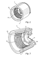
Fig 2 discloses a body member forming part of the camera offig 1 . -
Fig 3 is a view and partially a cross-section of the body member offig 2 . -
Fig 4 is a plan view of the body member offigs 2 and 3 . -
Fig 5 is a plan view of the body member offigs 2-4 . -
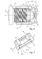
Fig 6 is a cross-section along line A-A infig 5 . -
Fig 7 is a cross-section along line B-B infig 5 . -
Fig 8 is a view of a closed loop flexible member. -
Fig 9 is a cross-section of the member offig 8 . -
Fig 10 is a view of an optical system. -
Fig 11 is a view of an electric circuit board comprising an image sensor. - As shown in
fig 1 , thedigital camera 1 comprises anoptical system 2a, animage sensor 3,electric circuitry 4 connected to theimage sensor 3, acable 5 connected to and extending from theelectric circuitry 4, and abody member 6 supporting and partly housing theoptical system 2, theimage sensor 3 and theelectric circuitry 4. The optical system (2a) is adapted to direct light towards the image sensor (3) along an optical path (P). Thecamera 1 further comprises ahousing 10 formed of two separate parts adapted to be connected to each other in a connected state to thereby form the housing. - As shown in
fig 11 , theimage sensor 3 andelectric circuitry 4 is arranged on acircuit board 7. - As shown in
fig 6 , thecircuit board 7 may be adapted to be attached to thebody member 6 and be held in place byscrews holes circuit board 7 and threaded into theholes body member 6. Other alternative designs are contemplated. Theholes optical system 2 is adapted to be threaded into thebody member 6. Thecircuit board 7 is provided withcoupling pins 7c to which the different strands of thecable 5 is detachably or non-detachably connected. - As shown in
fig 1 , thecable 5 is, at the other end of thecable 5, provided with a standard connector 5' to a computer or network. An USB-connector is shown infig 1 but other connectors are contemplated, such as a standard 8P8C connection (often referred to as RJ45 for telecommunication or Ethernet network communication). Other connectors considered suitable may also be used. Thecable 5 is an electrical cable for transmitting from theelectric circuitry 4 an electrical signal representing an image detected by theimage sensor 3. The cable is also used for providing electrical power to theelectric circuitry 4. The cable may in cross-section have a plurality of electrical wires encased in a casing of an elastic material, preferably an electrically insulating, elastic, polymeric material. - As shown in
fig 6 , the mounting system for the camera comprises in short afirst part 6 adapted to fixedly support animage sensor 3, asecond part 2 adapted to fixedly support anoptical system 2a, and a closed loop flexible member (also shown infig 8 and fig 9 ) which is adapted to be clamped between the first andsecond parts - The
second part 2 is rotatably adjustably supported by thefirst part 6. Thefirst part 6 and thesecond part 2 are provided with interacting obliquely oriented surfaces such that a relative rotation between thefirst part 6 and thesecond part 2 provides a relative translational movement. Thereby there is provided an adjustment of a distance d, along an optical path P, between theoptical system 2a and theimage sensor 3. By being able to adjust the distance between theoptical system 2a and theimage sensor 3 it is possible to provide correct focus of incoming light onto theimage sensor 3 even if any of the parts is not manufactured or assembled such that correct focus is immediately provided for. - The second part is a
fixture 2 holding theoptical system 2a. Thefixture 2 is as a circular cylinder provided with the obliquely oriented surfaces on the outwardly facing envelope surface. Thebody member 6 comprises a circular cylindrical envelope with the obliquely oriented surfaces on the inwardly facing envelope surface. Thesecond part 2 is rotatably insertable into thefirst part 6. The obliquely oriented surfaces of the first andsecond parts threads - As shown in
fig 6 andfig 4 , thebody member 6 comprises anabutment section 20 which is arranged along a geometrical closed loop L around the optical path P. The closed loopflexible member 12 is adapted to be clamped between thesecond part 2 and theabutment section 20. The closed loopflexible member 12 is adapted to flex and act as a spring in response to the adjustment of the adjustable distance d. - As is shown in
fig 4 , theabutment section 20 is formed as a groove extending along the geometrical closed loop L and facing thesecond part 2. Theabutment section 20 is provided with a plurality ofabutment portions 21 located at different positions along the loop L, i.e. at different angular positions relative to the optical path P. In the preferred embodiment there are fiveabutment portions 21 arranged around the loop L. Theabutment portions 21 are equidistantly arranged around the loop L. Alternatively, the number ofabutment portions 21 may be different from this. The number may e.g. be three or more, four or more, or five or more. Between theabutment portions 21 there is formed a plurality ofcavities 22. Theabutment portions 21 relative to thecavities 22 raised along the adjustable distance d towards thesecond part 2. In the preferred embodiment, thecavities 22 are formed of the parts of the groove not provided with the raisedabutment portions 21. Thus, theabutment section 20 comprises a plurality ofabutment portions 21 and a plurality ofcavities 22 alternatingly arranged along theabutment section 20. - It is considered appropriate that the abutment portions each have a length along the circumferential length of the geometrical loop L being between 1-15%, preferably between 2-8% of the circumferential length of the geometrical loop L. In the preferred embodiment each
abutment portion 21 has a length L21 being about 4% of the circumferential length of the geometrical loop L. The length of the geometrical loop L is measured along a diameter halfway between the inner diameter and outer diameter of theabutment section 20. - It is considered appropriate that the
abutment portions 21 together in total have a length L21 (i.e. the length of each portion times the number of portions) being between 10-75%, preferably between 10-50%, more preferably between 10-30% of the circumferential length of the geometrical loop L. In the preferred embodiment the total length of theabutment portions 21 is about 20% of the circumferential length of the geometrical loop L. - It is considered appropriate that the
abutment portions 21 each have a length L21 along the geometrical loop L being between 0.5 and 2 times a cross-sectional width W of the groove. In the preferred embodiment theabutment portions 21 each have a length L21 along the geometrical loop L being about 70% of the cross-sectional width W of the groove. - The closed loop
flexible member 12 is formed of a closed loop of elastomeric material, such as rubber. The elastomeric material has a hardness of about 30° Shore A. As shown infig 8 and fig 9 , theflexible member 12 has a uniform circular cross-section with a diameter D. Such a member is typically referred to as an O-ring. That is, the closed loopflexible member 12 has a cross-sectional dimension D' along the optical path P being said diameter D. It is considered appropriate that this dimension D' is greater than, preferably 2 times, a difference in distance between theabutment portions 21 and thesecond part 2 and thecavities 22 and thesecond part 2. In the preferred embodiment the difference in distance between theabutment portions 21 and thesecond part 2 and thecavities 22 and thesecond part 2 is the same as the height H by which theabutment portions 21 are raised above the bottom of the groove formed by thecavities 22. It is considered appropriate that this height H is about 20-150%, preferably about 25-80%, of the width W of the groove. In the preferred embodiment the height H is about 50% of the width W of the groove. - The closed loop
flexible member 12 has a cross-sectional dimension D" across the optical path P being the diameter D. This dimension D" is greater than a width W of the groove in which the closed loopflexible member 12 is arranged. The walls of the groove are continuous. Theflexible member 12 sealingly interacts with both thebody member 6 and thesecond part 2 and thereby a sealing function is provided extending around the optical path P and thereby it is prevented that dust or moisture penetrate to the void inside thebody member 6 where theimage sensor 3 is exposed towards theoptical system 3. - When assembled, there is provided a
digital camera 1 with abody member 6 fixedly supporting animage sensor 3, afixture 2 fixedly supporting anoptical system 2a, and a closed loopflexible member 12 which is clamped between thefixture 2 and thebody member 6. Thefixture 2 is rotatably adjustably supported by thebody member 6 such that a distance d, along an optical path P, between theimage sensor 3 and theoptical system 2a is adjustable. To provide the rotatably adjustably support thebody member 6 and thefixture 2 are provided with interacting obliquely oriented surfaces such that a relative rotation between thebody member 6 and thefixture 2 provides adjustment of the adjustable distance d. - It is contemplated that there are numerous modifications of the embodiments described herein, which are still within the scope of the invention as defined by the appended claims.
- The closed loop flexible member may e.g. have a non-uniform cross-section. The non-uniformity may be different along the circumference of the loop L. It may e.g. be a number of recesses or protrusions adapted to be used to orient the member in a correct angular position (angular in the sense of rotation along the circumference about the optical path P). The cross-section may also be non-circular. It may be square, rectangular, ellipsoid or other shapes being able to provide resilience in the direction of the adjustable distance d.
- It may also be noted that the flexible member in the preferred embodiment is clamped between the abutment section on the hand and both the fixture and the optical system on the other hand. The flexible member abuts the circumferential rim 2' of the
fixture 2 and also abuts atransparent surface 2a' in a sense forming part of theoptical system 2a. Alternatively, there might be no contact between the flexible member and the fixture at all and that all clamping force is transmitted via a transparent member within the perimeter of the fixture. Alternatively, the fixture is designed such that there will be no contact between the flexible member and the optical system and that all the clamping force is transmitted via the fixture as such.
Claims (15)
- Mounting system for a camera (1), the mounting system comprising a first part (6) adapted to fixedly support an image sensor (3), and a second part (2) adapted to fixedly support an optical system (2a),
wherein the second part (2) is rotatably adjustably supported by the first part (6) such that a distance (d), along an optical path (P), between the image sensor (3) and the optical system (2a) is adjustable,
wherein the first part (6) and the second part (2) are provided with interacting obliquely oriented surfaces (6d, 2d) such that a relative rotation between the first part (6) and the second part (2) provides adjustment of the adjustable distance (d),
wherein the first part (6) comprises an abutment section (20) which is arranged along a geometrical closed loop (L) around the optical path (P),
a closed loop flexible member (12) which is adapted to be clamped between the second part (2) and the abutment section (20), and which is adapted to flex in response to the adjustment of the adjustable distance (d),
wherein the abutment section (20) comprises a plurality of abutment portions (21) and a plurality of cavities (22) alternatingly arranged along the abutment section (20). - Mounting system according to claim 1, wherein the abutment portions (21) are, relative to the cavities (22), raised along the adjustable distance (d) towards the second part (2).
- Mounting system according to claim 1 or 2, wherein the abutment portions (21) each have a length (L21) along the circumferential length of the geometrical loop (L) being between 1-15%, preferably between 2-8% of the circumferential length of the geometrical loop (L).
- Mounting system according to anyone of claims 1-3, wherein the abutment portions (21) together in total have a length between 10-75%, preferably between 10-50%, more preferably between 10-30% of the circumferential length of the geometrical loop (L).
- Mounting system according to anyone of claims 1-4, wherein the abutment section (20) is formed as a groove, the groove extending along the geometrical closed loop (L) and facing the second part (2).
- Mounting system according to claim 5, wherein the abutment portions (21) each have a length (L21) along the geometrical loop (L) being between 0.5 and 2 times a cross-sectional width (W) of the groove.
- Mounting system according to anyone of claims 1-6, wherein the closed loop flexible member (12) is formed of a closed loop of elastomeric material, preferably having a hardness of between 20-70° Shore A, preferably 20-60° Shore A, more preferably 25-50° Shore A, and most preferably 25-40° Shore A.
- Mounting system according to anyone of claims 1-7, wherein the closed loop flexible member (12) has a cross-sectional dimension (D'), along the optical path (P), being greater than, preferably 2 times, a difference in distance between the abutment portions (21) and the second part (2) and the cavities (22) and the second part (2).
- Mounting system according to anyone of claims 5-8, wherein the closed loop flexible member (12) has a cross-sectional dimension (D"), across the optical path (P), being greater than a width (W) of the groove in which the closed loop flexible member (12) is arranged.
- Mounting system according to anyone of claims 1-9, wherein the closed loop flexible member (12) has a uniform cross-section, preferably circular.
- Mounting system according to anyone of claims 1, 3-4 and 6-10, wherein the abutment section (20) is formed as a groove, the groove extending along the geometrical closed loop (L) and facing the second part (2),
wherein the abutment portions (21) are relative to the cavities (22) raised from a bottom of the groove along the adjustable distance (d) towards the second part (2), and
wherein the abutment portions (21) are raised a distance (H) being between 0.2 to 0.8 times a cross-sectional width (W) of the groove. - Mounting system according to anyone of claims 1-11, wherein the closed loop flexible member (12) is adapted to sealingly interact with both the first part (6) and the second part (2) such that there is a seal being formed between the first part (6) and the second part (2) and extending around the optical path (P).
- Mounting system according to anyone of claims 1-12, wherein the second part (2) is insertable into the first part (6), wherein the obliquely oriented surfaces (6d) of the first part (6) are provided on an inwardly facing envelope surface and the obliquely oriented surfaces (2d) of the second part (2) are provided on an outwardly facing envelope surface.
- Mounting system according to anyone of claims 1-13, wherein the first part is a body member (6) fixedly supporting an image sensor (3), and wherein the second part is an fixture (2) fixedly supporting an optical system (2a).
- Camera (1) comprising,
a body member (6) fixedly supporting an image sensor (3), and
a fixture (2) fixedly supporting an optical system (2a),
wherein the fixture (2) is rotatably adjustably supported by the body member (6) such that a distance (d), along an optical path (P), between the image sensor (3) and the optical system (2a) is adjustable,
wherein the body member (6) and the fixture (2) are provided with interacting obliquely oriented surfaces (6d, 2d) such that a relative rotation between the body member (6) and the fixture (2) provides adjustment of the adjustable distance (d),
wherein the body member (6) comprises an abutment section (20) which is arranged along a geometrical closed loop (L) around the optical path (P),
wherein the camera (1) further comprises a closed loop flexible member (12) which is adapted to be clamped between the fixture (2) and/or the optical system (2a) and the abutment section (20), and which is adapted to flex in response to the adjustment of the adjustable distance (d),
wherein the abutment section (20) comprises a plurality of abutment portions (21) and a plurality of cavities (22) alternatingly arranged along the abutment section (20).
Priority Applications (1)
| Application Number | Priority Date | Filing Date | Title |
|---|---|---|---|
| EP15169376.9A EP3098652B1 (en) | 2015-05-27 | 2015-05-27 | Mounting system for a camera and a camera |
Applications Claiming Priority (1)
| Application Number | Priority Date | Filing Date | Title |
|---|---|---|---|
| EP15169376.9A EP3098652B1 (en) | 2015-05-27 | 2015-05-27 | Mounting system for a camera and a camera |
Publications (2)
| Publication Number | Publication Date |
|---|---|
| EP3098652A1 true EP3098652A1 (en) | 2016-11-30 |
| EP3098652B1 EP3098652B1 (en) | 2017-11-08 |
Family
ID=53268715
Family Applications (1)
| Application Number | Title | Priority Date | Filing Date |
|---|---|---|---|
| EP15169376.9A Active EP3098652B1 (en) | 2015-05-27 | 2015-05-27 | Mounting system for a camera and a camera |
Country Status (1)
| Country | Link |
|---|---|
| EP (1) | EP3098652B1 (en) |
Citations (3)
| Publication number | Priority date | Publication date | Assignee | Title |
|---|---|---|---|---|
| EP1174748A2 (en) * | 2000-07-17 | 2002-01-23 | Kabushiki Kaisha Toshiba | Optical lens unit having a mechanism for adjusting the focal point of the optical lens |
| US20070077051A1 (en) * | 2005-10-03 | 2007-04-05 | Toor John W | Micro camera module with discrete manual focal positions |
| DE102011002299A1 (en) * | 2011-04-28 | 2012-10-31 | Sick Ag | optics carrier |
-
2015
- 2015-05-27 EP EP15169376.9A patent/EP3098652B1/en active Active
Patent Citations (3)
| Publication number | Priority date | Publication date | Assignee | Title |
|---|---|---|---|---|
| EP1174748A2 (en) * | 2000-07-17 | 2002-01-23 | Kabushiki Kaisha Toshiba | Optical lens unit having a mechanism for adjusting the focal point of the optical lens |
| US20070077051A1 (en) * | 2005-10-03 | 2007-04-05 | Toor John W | Micro camera module with discrete manual focal positions |
| DE102011002299A1 (en) * | 2011-04-28 | 2012-10-31 | Sick Ag | optics carrier |
Also Published As
| Publication number | Publication date |
|---|---|
| EP3098652B1 (en) | 2017-11-08 |
Similar Documents
| Publication | Publication Date | Title |
|---|---|---|
| EP2413438A1 (en) | Cable connector | |
| KR102468410B1 (en) | Camera module | |
| US20220263265A1 (en) | Multipolar Connector | |
| US20160260561A1 (en) | Universal Box System | |
| US5136121A (en) | Cable terminals | |
| KR20100112085A (en) | An interconnection system | |
| US20160240957A1 (en) | Sealed electrical cable connector | |
| US11088518B2 (en) | Mounting mechanism for an electrical device | |
| EP2418744A1 (en) | Seal device for sealing a connector | |
| CN109768419B (en) | Connector with a locking member | |
| CN108418159A (en) | Grommet and grommet device for sealing cable in cable bushing | |
| US20200280660A1 (en) | Apparatus body of image pickup apparatus and lens adapter for equipping interchangeable lens to apparatus body | |
| CN106210462B (en) | Outer cover and video camera including outer cover | |
| WO2009005416A1 (en) | Cable fitting arrangement | |
| CA1155910A (en) | Flexible connector for high voltage arrester | |
| EP3098652B1 (en) | Mounting system for a camera and a camera | |
| CN102640373A (en) | Wire separator suitable for use in a cable splice enclosure | |
| JP7006638B2 (en) | connector | |
| US9825401B2 (en) | Connector with a biasing elastic member | |
| WO2009150258A1 (en) | Attachment of a hook to a hearing device | |
| TWI575822B (en) | Connector | |
| US10541524B2 (en) | Electronic apparatus | |
| JPS62213015A (en) | Moisture-proof electric contact | |
| KR101647965B1 (en) | Waterproof case | |
| US10687134B2 (en) | Disconnectable connector with provisions for motion in two axes |
Legal Events
| Date | Code | Title | Description |
|---|---|---|---|
| PUAI | Public reference made under article 153(3) epc to a published international application that has entered the european phase |
Free format text: ORIGINAL CODE: 0009012 |
|
| 17P | Request for examination filed |
Effective date: 20160421 |
|
| AK | Designated contracting states |
Kind code of ref document: A1 Designated state(s): AL AT BE BG CH CY CZ DE DK EE ES FI FR GB GR HR HU IE IS IT LI LT LU LV MC MK MT NL NO PL PT RO RS SE SI SK SM TR |
|
| AX | Request for extension of the european patent |
Extension state: BA ME |
|
| GRAP | Despatch of communication of intention to grant a patent |
Free format text: ORIGINAL CODE: EPIDOSNIGR1 |
|
| STAA | Information on the status of an ep patent application or granted ep patent |
Free format text: STATUS: GRANT OF PATENT IS INTENDED |
|
| INTG | Intention to grant announced |
Effective date: 20170117 |
|
| GRAJ | Information related to disapproval of communication of intention to grant by the applicant or resumption of examination proceedings by the epo deleted |
Free format text: ORIGINAL CODE: EPIDOSDIGR1 |
|
| STAA | Information on the status of an ep patent application or granted ep patent |
Free format text: STATUS: EXAMINATION IS IN PROGRESS |
|
| INTC | Intention to grant announced (deleted) | ||
| GRAP | Despatch of communication of intention to grant a patent |
Free format text: ORIGINAL CODE: EPIDOSNIGR1 |
|
| STAA | Information on the status of an ep patent application or granted ep patent |
Free format text: STATUS: GRANT OF PATENT IS INTENDED |
|
| INTG | Intention to grant announced |
Effective date: 20170802 |
|
| GRAS | Grant fee paid |
Free format text: ORIGINAL CODE: EPIDOSNIGR3 |
|
| GRAA | (expected) grant |
Free format text: ORIGINAL CODE: 0009210 |
|
| STAA | Information on the status of an ep patent application or granted ep patent |
Free format text: STATUS: THE PATENT HAS BEEN GRANTED |
|
| AK | Designated contracting states |
Kind code of ref document: B1 Designated state(s): AL AT BE BG CH CY CZ DE DK EE ES FI FR GB GR HR HU IE IS IT LI LT LU LV MC MK MT NL NO PL PT RO RS SE SI SK SM TR |
|
| REG | Reference to a national code |
Ref country code: GB Ref legal event code: FG4D |
|
| REG | Reference to a national code |
Ref country code: CH Ref legal event code: EP Ref country code: AT Ref legal event code: REF Ref document number: 944703 Country of ref document: AT Kind code of ref document: T Effective date: 20171115 |
|
| REG | Reference to a national code |
Ref country code: IE Ref legal event code: FG4D |
|
| REG | Reference to a national code |
Ref country code: DE Ref legal event code: R096 Ref document number: 602015005804 Country of ref document: DE |
|
| REG | Reference to a national code |
Ref country code: SE Ref legal event code: TRGR |
|
| REG | Reference to a national code |
Ref country code: NL Ref legal event code: MP Effective date: 20171108 |
|
| REG | Reference to a national code |
Ref country code: LT Ref legal event code: MG4D |
|
| REG | Reference to a national code |
Ref country code: AT Ref legal event code: MK05 Ref document number: 944703 Country of ref document: AT Kind code of ref document: T Effective date: 20171108 |
|
| PG25 | Lapsed in a contracting state [announced via postgrant information from national office to epo] |
Ref country code: NL Free format text: LAPSE BECAUSE OF FAILURE TO SUBMIT A TRANSLATION OF THE DESCRIPTION OR TO PAY THE FEE WITHIN THE PRESCRIBED TIME-LIMIT Effective date: 20171108 Ref country code: LT Free format text: LAPSE BECAUSE OF FAILURE TO SUBMIT A TRANSLATION OF THE DESCRIPTION OR TO PAY THE FEE WITHIN THE PRESCRIBED TIME-LIMIT Effective date: 20171108 Ref country code: FI Free format text: LAPSE BECAUSE OF FAILURE TO SUBMIT A TRANSLATION OF THE DESCRIPTION OR TO PAY THE FEE WITHIN THE PRESCRIBED TIME-LIMIT Effective date: 20171108 Ref country code: ES Free format text: LAPSE BECAUSE OF FAILURE TO SUBMIT A TRANSLATION OF THE DESCRIPTION OR TO PAY THE FEE WITHIN THE PRESCRIBED TIME-LIMIT Effective date: 20171108 Ref country code: NO Free format text: LAPSE BECAUSE OF FAILURE TO SUBMIT A TRANSLATION OF THE DESCRIPTION OR TO PAY THE FEE WITHIN THE PRESCRIBED TIME-LIMIT Effective date: 20180208 |
|
| REG | Reference to a national code |
Ref country code: FR Ref legal event code: PLFP Year of fee payment: 4 |
|
| PG25 | Lapsed in a contracting state [announced via postgrant information from national office to epo] |
Ref country code: IS Free format text: LAPSE BECAUSE OF FAILURE TO SUBMIT A TRANSLATION OF THE DESCRIPTION OR TO PAY THE FEE WITHIN THE PRESCRIBED TIME-LIMIT Effective date: 20180308 Ref country code: RS Free format text: LAPSE BECAUSE OF FAILURE TO SUBMIT A TRANSLATION OF THE DESCRIPTION OR TO PAY THE FEE WITHIN THE PRESCRIBED TIME-LIMIT Effective date: 20171108 Ref country code: GR Free format text: LAPSE BECAUSE OF FAILURE TO SUBMIT A TRANSLATION OF THE DESCRIPTION OR TO PAY THE FEE WITHIN THE PRESCRIBED TIME-LIMIT Effective date: 20180209 Ref country code: LV Free format text: LAPSE BECAUSE OF FAILURE TO SUBMIT A TRANSLATION OF THE DESCRIPTION OR TO PAY THE FEE WITHIN THE PRESCRIBED TIME-LIMIT Effective date: 20171108 Ref country code: BG Free format text: LAPSE BECAUSE OF FAILURE TO SUBMIT A TRANSLATION OF THE DESCRIPTION OR TO PAY THE FEE WITHIN THE PRESCRIBED TIME-LIMIT Effective date: 20180208 Ref country code: AT Free format text: LAPSE BECAUSE OF FAILURE TO SUBMIT A TRANSLATION OF THE DESCRIPTION OR TO PAY THE FEE WITHIN THE PRESCRIBED TIME-LIMIT Effective date: 20171108 Ref country code: HR Free format text: LAPSE BECAUSE OF FAILURE TO SUBMIT A TRANSLATION OF THE DESCRIPTION OR TO PAY THE FEE WITHIN THE PRESCRIBED TIME-LIMIT Effective date: 20171108 |
|
| PG25 | Lapsed in a contracting state [announced via postgrant information from national office to epo] |
Ref country code: DK Free format text: LAPSE BECAUSE OF FAILURE TO SUBMIT A TRANSLATION OF THE DESCRIPTION OR TO PAY THE FEE WITHIN THE PRESCRIBED TIME-LIMIT Effective date: 20171108 Ref country code: CY Free format text: LAPSE BECAUSE OF FAILURE TO SUBMIT A TRANSLATION OF THE DESCRIPTION OR TO PAY THE FEE WITHIN THE PRESCRIBED TIME-LIMIT Effective date: 20171108 Ref country code: EE Free format text: LAPSE BECAUSE OF FAILURE TO SUBMIT A TRANSLATION OF THE DESCRIPTION OR TO PAY THE FEE WITHIN THE PRESCRIBED TIME-LIMIT Effective date: 20171108 Ref country code: SK Free format text: LAPSE BECAUSE OF FAILURE TO SUBMIT A TRANSLATION OF THE DESCRIPTION OR TO PAY THE FEE WITHIN THE PRESCRIBED TIME-LIMIT Effective date: 20171108 Ref country code: CZ Free format text: LAPSE BECAUSE OF FAILURE TO SUBMIT A TRANSLATION OF THE DESCRIPTION OR TO PAY THE FEE WITHIN THE PRESCRIBED TIME-LIMIT Effective date: 20171108 |
|
| REG | Reference to a national code |
Ref country code: DE Ref legal event code: R097 Ref document number: 602015005804 Country of ref document: DE |
|
| PG25 | Lapsed in a contracting state [announced via postgrant information from national office to epo] |
Ref country code: PL Free format text: LAPSE BECAUSE OF FAILURE TO SUBMIT A TRANSLATION OF THE DESCRIPTION OR TO PAY THE FEE WITHIN THE PRESCRIBED TIME-LIMIT Effective date: 20171108 Ref country code: IT Free format text: LAPSE BECAUSE OF FAILURE TO SUBMIT A TRANSLATION OF THE DESCRIPTION OR TO PAY THE FEE WITHIN THE PRESCRIBED TIME-LIMIT Effective date: 20171108 Ref country code: SM Free format text: LAPSE BECAUSE OF FAILURE TO SUBMIT A TRANSLATION OF THE DESCRIPTION OR TO PAY THE FEE WITHIN THE PRESCRIBED TIME-LIMIT Effective date: 20171108 |
|
| PLBE | No opposition filed within time limit |
Free format text: ORIGINAL CODE: 0009261 |
|
| STAA | Information on the status of an ep patent application or granted ep patent |
Free format text: STATUS: NO OPPOSITION FILED WITHIN TIME LIMIT |
|
| 26N | No opposition filed |
Effective date: 20180809 |
|
| PG25 | Lapsed in a contracting state [announced via postgrant information from national office to epo] |
Ref country code: SI Free format text: LAPSE BECAUSE OF FAILURE TO SUBMIT A TRANSLATION OF THE DESCRIPTION OR TO PAY THE FEE WITHIN THE PRESCRIBED TIME-LIMIT Effective date: 20171108 |
|
| REG | Reference to a national code |
Ref country code: CH Ref legal event code: PL |
|
| REG | Reference to a national code |
Ref country code: BE Ref legal event code: MM Effective date: 20180531 |
|
| PG25 | Lapsed in a contracting state [announced via postgrant information from national office to epo] |
Ref country code: MC Free format text: LAPSE BECAUSE OF FAILURE TO SUBMIT A TRANSLATION OF THE DESCRIPTION OR TO PAY THE FEE WITHIN THE PRESCRIBED TIME-LIMIT Effective date: 20171108 |
|
| REG | Reference to a national code |
Ref country code: IE Ref legal event code: MM4A |
|
| PG25 | Lapsed in a contracting state [announced via postgrant information from national office to epo] |
Ref country code: LI Free format text: LAPSE BECAUSE OF NON-PAYMENT OF DUE FEES Effective date: 20180531 Ref country code: CH Free format text: LAPSE BECAUSE OF NON-PAYMENT OF DUE FEES Effective date: 20180531 |
|
| PG25 | Lapsed in a contracting state [announced via postgrant information from national office to epo] |
Ref country code: LU Free format text: LAPSE BECAUSE OF NON-PAYMENT OF DUE FEES Effective date: 20180527 |
|
| PG25 | Lapsed in a contracting state [announced via postgrant information from national office to epo] |
Ref country code: IE Free format text: LAPSE BECAUSE OF NON-PAYMENT OF DUE FEES Effective date: 20180527 |
|
| PG25 | Lapsed in a contracting state [announced via postgrant information from national office to epo] |
Ref country code: BE Free format text: LAPSE BECAUSE OF NON-PAYMENT OF DUE FEES Effective date: 20180531 |
|
| PG25 | Lapsed in a contracting state [announced via postgrant information from national office to epo] |
Ref country code: MT Free format text: LAPSE BECAUSE OF NON-PAYMENT OF DUE FEES Effective date: 20180527 |
|
| PG25 | Lapsed in a contracting state [announced via postgrant information from national office to epo] |
Ref country code: TR Free format text: LAPSE BECAUSE OF FAILURE TO SUBMIT A TRANSLATION OF THE DESCRIPTION OR TO PAY THE FEE WITHIN THE PRESCRIBED TIME-LIMIT Effective date: 20171108 |
|
| PG25 | Lapsed in a contracting state [announced via postgrant information from national office to epo] |
Ref country code: PT Free format text: LAPSE BECAUSE OF FAILURE TO SUBMIT A TRANSLATION OF THE DESCRIPTION OR TO PAY THE FEE WITHIN THE PRESCRIBED TIME-LIMIT Effective date: 20171108 |
|
| PG25 | Lapsed in a contracting state [announced via postgrant information from national office to epo] |
Ref country code: MK Free format text: LAPSE BECAUSE OF NON-PAYMENT OF DUE FEES Effective date: 20171108 Ref country code: RO Free format text: LAPSE BECAUSE OF FAILURE TO SUBMIT A TRANSLATION OF THE DESCRIPTION OR TO PAY THE FEE WITHIN THE PRESCRIBED TIME-LIMIT Effective date: 20171108 Ref country code: HU Free format text: LAPSE BECAUSE OF FAILURE TO SUBMIT A TRANSLATION OF THE DESCRIPTION OR TO PAY THE FEE WITHIN THE PRESCRIBED TIME-LIMIT; INVALID AB INITIO Effective date: 20150527 |
|
| PG25 | Lapsed in a contracting state [announced via postgrant information from national office to epo] |
Ref country code: AL Free format text: LAPSE BECAUSE OF FAILURE TO SUBMIT A TRANSLATION OF THE DESCRIPTION OR TO PAY THE FEE WITHIN THE PRESCRIBED TIME-LIMIT Effective date: 20171108 |
|
| P01 | Opt-out of the competence of the unified patent court (upc) registered |
Effective date: 20230505 |
|
| PGFP | Annual fee paid to national office [announced via postgrant information from national office to epo] |
Ref country code: DE Payment date: 20250423 Year of fee payment: 11 |
|
| PGFP | Annual fee paid to national office [announced via postgrant information from national office to epo] |
Ref country code: GB Payment date: 20250423 Year of fee payment: 11 |
|
| PGFP | Annual fee paid to national office [announced via postgrant information from national office to epo] |
Ref country code: FR Payment date: 20250423 Year of fee payment: 11 |
|
| PGFP | Annual fee paid to national office [announced via postgrant information from national office to epo] |
Ref country code: SE Payment date: 20250423 Year of fee payment: 11 |