EP3098592B1 - Mehrkomponentengasanalysesystem und mehrkomponentengasanalyseverfahren - Google Patents
Mehrkomponentengasanalysesystem und mehrkomponentengasanalyseverfahren Download PDFInfo
- Publication number
- EP3098592B1 EP3098592B1 EP16170116.4A EP16170116A EP3098592B1 EP 3098592 B1 EP3098592 B1 EP 3098592B1 EP 16170116 A EP16170116 A EP 16170116A EP 3098592 B1 EP3098592 B1 EP 3098592B1
- Authority
- EP
- European Patent Office
- Prior art keywords
- component
- gas
- components
- component gas
- density
- Prior art date
- Legal status (The legal status is an assumption and is not a legal conclusion. Google has not performed a legal analysis and makes no representation as to the accuracy of the status listed.)
- Active
Links
Images

Classifications
-
- G—PHYSICS
- G01—MEASURING; TESTING
- G01N—INVESTIGATING OR ANALYSING MATERIALS BY DETERMINING THEIR CHEMICAL OR PHYSICAL PROPERTIES
- G01N21/00—Investigating or analysing materials by the use of optical means, i.e. using sub-millimetre waves, infrared, visible or ultraviolet light
- G01N21/17—Systems in which incident light is modified in accordance with the properties of the material investigated
- G01N21/25—Colour; Spectral properties, i.e. comparison of effect of material on the light at two or more different wavelengths or wavelength bands
- G01N21/31—Investigating relative effect of material at wavelengths characteristic of specific elements or molecules, e.g. atomic absorption spectrometry
- G01N21/35—Investigating relative effect of material at wavelengths characteristic of specific elements or molecules, e.g. atomic absorption spectrometry using infrared light
- G01N21/3504—Investigating relative effect of material at wavelengths characteristic of specific elements or molecules, e.g. atomic absorption spectrometry using infrared light for analysing gases, e.g. multi-gas analysis
-
- G—PHYSICS
- G01—MEASURING; TESTING
- G01N—INVESTIGATING OR ANALYSING MATERIALS BY DETERMINING THEIR CHEMICAL OR PHYSICAL PROPERTIES
- G01N21/00—Investigating or analysing materials by the use of optical means, i.e. using sub-millimetre waves, infrared, visible or ultraviolet light
- G01N21/84—Systems specially adapted for particular applications
- G01N21/85—Investigating moving fluids or granular solids
-
- G—PHYSICS
- G01—MEASURING; TESTING
- G01N—INVESTIGATING OR ANALYSING MATERIALS BY DETERMINING THEIR CHEMICAL OR PHYSICAL PROPERTIES
- G01N33/00—Investigating or analysing materials by specific methods not covered by groups G01N1/00 - G01N31/00
- G01N33/0004—Gaseous mixtures, e.g. polluted air
- G01N33/0009—General constructional details of gas analysers, e.g. portable test equipment
- G01N33/0027—General constructional details of gas analysers, e.g. portable test equipment concerning the detector
- G01N33/0031—General constructional details of gas analysers, e.g. portable test equipment concerning the detector comprising two or more sensors, e.g. a sensor array
- G01N33/0032—General constructional details of gas analysers, e.g. portable test equipment concerning the detector comprising two or more sensors, e.g. a sensor array using two or more different physical functioning modes
-
- G—PHYSICS
- G01—MEASURING; TESTING
- G01N—INVESTIGATING OR ANALYSING MATERIALS BY DETERMINING THEIR CHEMICAL OR PHYSICAL PROPERTIES
- G01N9/00—Investigating density or specific gravity of materials; Analysing materials by determining density or specific gravity
- G01N9/36—Analysing materials by measuring the density or specific gravity, e.g. determining quantity of moisture
-
- F—MECHANICAL ENGINEERING; LIGHTING; HEATING; WEAPONS; BLASTING
- F23—COMBUSTION APPARATUS; COMBUSTION PROCESSES
- F23K—FEEDING FUEL TO COMBUSTION APPARATUS
- F23K5/00—Feeding or distributing other fuel to combustion apparatus
- F23K5/002—Gaseous fuel
-
- G—PHYSICS
- G01—MEASURING; TESTING
- G01N—INVESTIGATING OR ANALYSING MATERIALS BY DETERMINING THEIR CHEMICAL OR PHYSICAL PROPERTIES
- G01N2201/00—Features of devices classified in G01N21/00
- G01N2201/12—Circuits of general importance; Signal processing
-
- G—PHYSICS
- G01—MEASURING; TESTING
- G01N—INVESTIGATING OR ANALYSING MATERIALS BY DETERMINING THEIR CHEMICAL OR PHYSICAL PROPERTIES
- G01N33/00—Investigating or analysing materials by specific methods not covered by groups G01N1/00 - G01N31/00
- G01N33/0004—Gaseous mixtures, e.g. polluted air
- G01N33/0009—General constructional details of gas analysers, e.g. portable test equipment
- G01N33/0027—General constructional details of gas analysers, e.g. portable test equipment concerning the detector
- G01N33/0036—General constructional details of gas analysers, e.g. portable test equipment concerning the detector specially adapted to detect a particular component
-
- G—PHYSICS
- G01—MEASURING; TESTING
- G01N—INVESTIGATING OR ANALYSING MATERIALS BY DETERMINING THEIR CHEMICAL OR PHYSICAL PROPERTIES
- G01N33/00—Investigating or analysing materials by specific methods not covered by groups G01N1/00 - G01N31/00
- G01N33/0004—Gaseous mixtures, e.g. polluted air
- G01N33/0009—General constructional details of gas analysers, e.g. portable test equipment
- G01N33/0062—General constructional details of gas analysers, e.g. portable test equipment concerning the measuring method or the display, e.g. intermittent measurement or digital display
-
- G—PHYSICS
- G01—MEASURING; TESTING
- G01N—INVESTIGATING OR ANALYSING MATERIALS BY DETERMINING THEIR CHEMICAL OR PHYSICAL PROPERTIES
- G01N33/00—Investigating or analysing materials by specific methods not covered by groups G01N1/00 - G01N31/00
- G01N33/0004—Gaseous mixtures, e.g. polluted air
- G01N33/0009—General constructional details of gas analysers, e.g. portable test equipment
- G01N33/0062—General constructional details of gas analysers, e.g. portable test equipment concerning the measuring method or the display, e.g. intermittent measurement or digital display
- G01N33/0068—General constructional details of gas analysers, e.g. portable test equipment concerning the measuring method or the display, e.g. intermittent measurement or digital display using a computer specifically programmed
-
- G—PHYSICS
- G01—MEASURING; TESTING
- G01N—INVESTIGATING OR ANALYSING MATERIALS BY DETERMINING THEIR CHEMICAL OR PHYSICAL PROPERTIES
- G01N33/00—Investigating or analysing materials by specific methods not covered by groups G01N1/00 - G01N31/00
- G01N33/22—Fuels; Explosives
- G01N33/225—Gaseous fuels, e.g. natural gas
Definitions
- the present invention relates to a multi-component gas analysis system and a multi-component gas analysis method.
- concentration of a specific component contained in a multi-component gas is measured using a gas chromatography.
- the gas chromatography includes a tubular route called a column and a gas concentration detector provided at the end of the column.
- the multi-component gas is transmitted thorough the column.
- Each of the components in the multi-component gas travels through the column at a different speed and is distinguishable (separated) thereby.
- the concentration of each component contained in the multi-component gas is determined by measuring the amount of each separated component with the gas concentration detector.
- the concentration of the specific component contained in the multi-component gas may also be measured using a spectrometric analysis device.
- the spectrometric analysis device includes light source that emits light of a specific wavelength (e.g., infrared light), and a photodetector for receiving the light from the light source.
- the light emitted from the light source is irradiated to the multi-component gas.
- the light transmitted through the multi-component gas is received by the photodetector and the absorption spectrum (the spectrum of absorbance for light at each wavelength) of the received light is determined. Thereby, the concentration of each component contained in the multi-component gas is measured.
- Japanese Unexamined Patent Application, First Publication No. 2000-346801 discloses a multi-component gas analysis method using a FT-IR (Fourier Transform Infrared) spectrometric analysis meter.
- Japanese Unexamined Patent Application, First Publication No. 2001-099781 discloses a gas analysis method using infrared absorption spectrophotometry.
- Japanese Unexamined Patent Application, First Publication No. 2013-174558 discloses a multi-component gas measurement system using a FT-IR device and an SPI-MS (Single Photon Ionization Mass Spectrometry) device.
- the gas chromatograph described above can perform a measurement of concentrations for a plurality of components contained in the multi-component gas with sufficient accuracy, but it takes a long time such as about several minutes to perform the measurement. Therefore, the gas chromatograph is not suitable for the use that needs to analyze continuously the component contained in the multi-component gas (for example, a management use of a process that needs to perform an adjustment of heat quantity and an observation of components contained in a combustion gas).
- the spectrometric analysis device described above can perform a measurement in a short time such as about several seconds. Therefore, the spectrometric analysis device can be used also for a use that needs to analyze continuously the component contained in the multi-component gas. However, the spectrometric analysis device measures the concentration of the component contained in the multi-component gas based on the absorbance of light. Therefore, the kind of components that can be measured is limited.
- the spectrometric analysis device can measure a component that absorbs infrared light (for example, methane (CH 4 ), ethane (C 2 H 6 ), or the like), while it is difficult for the spectrometric analysis device to measure a component that does not absorb infrared light (for example, diatomic molecules, such as hydrogen (H 2 ), oxygen (O 2 ), nitrogen (N 2 ), or the like).
- a component that absorbs infrared light for example, methane (CH 4 ), ethane (C 2 H 6 ), or the like
- a component that does not absorb infrared light for example, diatomic molecules, such as hydrogen (H 2 ), oxygen (O 2 ), nitrogen (N 2 ), or the like.
- the above-described component that does not absorb infrared light is contained in the multi-component gas
- the ratio of the component component ratio
- a plurality of components that do not absorb infrared light are contained in the multi-component gas, it is impossible to obtain the component ratio of each of these components.
- DE 199 21 167 A1 relates to a method and an arrangement for measuring the calorific value and/or the Wobbe index of combustible gas, especially natural gas.
- Said method comprises the following steps: a) the sonic speed or the density of the combustible gas is measured; b) the combustible gas is exposed to infrared radiation and the proportion of the infrared radiation that is absorbed by the combustible gas is measured by means of a sensor arrangement; c) and the calorific value and/or the Wobbe index is derived from the two measuring signals.
- DE102008029553 B3 describes the quality determination of biogas using infrared spectroscopy and thermal conductivity measurements.
- the present invention provides a multi-component gas analysis system and a multi-component gas analysis method that can continuously obtain a component ratio for each component contained in the multi-component gas even in a case in which a plurality of components that cannot be analyzed using the spectrometric analysis device are contained in the multi-component gas.
- the density measurement device that measures the density of the multi-component gas is provided in addition to the spectrometric analysis device that analyzes the component ratio of each measurable component (first component) contained in the multi-component gas. Further, the component ratio of each unmeasurable component (second component) that cannot be analyzed by the spectrometric analysis device of the components contained in the multi-component gas is obtained using the analysis result of the spectrometric analysis device and the measurement result of density measurement device. Therefore, even in a case in which a plurality of components (second components) that cannot be analyzed by the spectrometric analysis device are contained in the multi-component gas, it is possible to obtain the component ratio of each component contained in the multi-component gas continuously.
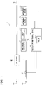
- Fig. 1 is a block diagram illustrating a principal part composition of the multi-component gas analysis system in accordance with an embodiment of the present invention.
- the multi-component gas analysis system in accordance with this embodiment includes a spectrometric analysis device 11, a density measurement device 12, a pressure measurement device 13, a temperature measurement device 14, and an calculation and control device 15 (calculation device), and analyzes components contained in the multi-component gas G.
- the multi-component gas G includes methane (CH 4 ), ethane (C 2 H 6 ), propane (C 3 H 8 ), butane (C 4 H 10 ), pentane (C 5 H 12 ), hydrogen (H 2 ), and nitrogen (N 2 ).
- methane CH 4
- ethane C 2 H 6
- propane C 3 H 8
- butane C 4 H 10
- pentane C 5 H 12
- hydrogen H 2
- nitrogen nitrogen
- components that absorb infrared light among the components contained in the multi-component gas are referred to as a first component, and components that do not absorb infrared light are referred to as a second component.
- Methane, ethane, propane, butane, and pentane are the first component.
- Hydrogen and nitrogen are the second component.
- the spectrometric analysis device can analyze the first component, while the spectrometric analysis device cannot analyze the second component.
- the multi-component gas G is obtained by a gas mixing machine MX mixing a natural gas G1 including methane, ethane, propane, butane, pentane, and nitrogen with a hydrogen gas G2.
- the hydrogen gas G2 is obtained by decomposing water with an electric power obtained by, for example, a wind power generation.
- the hydrogen gas G2 is used by being mixed with the natural gas G1.
- the valve V for adjusting the amount of supply of the hydrogen gas G2 is provided in the supply course of the hydrogen gas G2 to the gas mixing machine MX.
- the spectrometric analysis device 11 analyzes each component of methane, ethane, propane, butane, and pentane contained in the multi-component gas G based on the absorption spectrum of the light (for example, infrared light) transmitted through the multi-component gas G.
- the spectrometric analysis device 11 cannot analyze components such as hydrogen and nitrogen other than methane, ethane, propane, butane, and pentane contained in the multi-component gas G, because these components (hydrogen and nitrogen) do not absorb the light transmitted through the multi-component gas G.
- the spectrometric analysis device 11 is, for example, a laser gas analysis meter that measures each component contained in the multi-component gas G based on the absorption spectrum of the laser light that is irradiated on the multi-component gas G with laser light (for example, infrared laser light) and is transmitted through the multi-component gas G.
- laser light for example, infrared laser light
- the density measurement device 12 measures the density (mass per unit volume) of the multi-component gas G. That is, the density measurement device 12 measures the density of the multi-component gas G containing the component (methane, ethane, propane, butane, and pentane) that can be analyzed by the spectrometric analysis device 11 and the component (hydrogen and nitrogen) that cannot be analyzed by the spectrometric analysis device 11.
- the density measurement device 12 is provided in order to obtain the component ratio of the component (hydrogen and nitrogen) that cannot be analyzed by the spectrometric analysis device 11.
- the density measurement device 12 is a gas density meter, for example.
- the pressure measurement device 13 measures the pressure of the multi-component gas G.
- the temperature measurement device 14 measures the temperature of the multi-component gas G.
- the pressure measurement device 13 and the temperature measurement device 14 are provided in order to correct the density of the multi-component gas G that varies depending on the pressure and the temperature of the multi-component gas G (for example, correct the density into a value at 1 atmosphere and 0 degree C).
- the pressure and the temperature of the multi-component gas G are constant and known in advance, it is possible to omit the pressure measurement device 13 and temperature measurement device 14.
- the density of gas is obtained by the product of the molecularity per unit volume (the number of Mol) and the molecular weight.
- the molecularity n per unit volume (namely, density of gas) changes based on the gaseous pressure p and the temperature T.
- the pressure measurement device 13 and the temperature measurement device 14 are provided in order to correct this change.
- the calculation and control device 15 obtains the component ratio of the component (hydrogen and nitrogen), which cannot be analyzed by the spectrometric analysis device 11, among the components contained in the multi-component gas G using the analysis result of the spectrometric analysis device 11 and the measurement result of the density measurement device 12. Specifically, the calculation and control device 15 compares the density of the multi-component gas G computed using the analysis result of the spectrometric analysis device 11 with the density measured by the density measurement device 12, and obtains the component ratio of hydrogen and nitrogen contained in the multi-component gas G. When the pressure measurement device 13 and the temperature measurement device 14 are provided, the calculation and control device 15 obtains the component ratio of hydrogen and nitrogen further using the measurement results of the pressure measurement device 13 and the temperature measurement device 14.
- a, b, c, d, and e represent the component ratio of methane, ethane, propane, butane, and pentane, which are contained in the multi-component gas G, respectively.
- r represents the ratio of hydrogen among the component (hydrogen and nitrogen) in the multi-component gas G except methane, ethane, propane, butane, and pentane.
- ⁇ 1 at the right side of the above equation (1) represents the density of methane, ethane, propane, butane, and pentane and is expressed by the following equation (2).
- p2 of the right side of the above equation (1) represents the density of hydrogen and nitrogen and is expressed by the following equation (3).
- k in the following equations (2) and (3) represents a constant that is determined by the pressure and temperature of the multi-component gas G.
- the component ratios (the variables a, b, c, d, and e in the above equations (2) and (3)) of methane, ethane, propane, butane, and pentane, which are contained in the multi-component gas G, are obtained from the analysis result of the spectrometric analysis device 11.
- the calculation and control device 15 compares the density ⁇ of the multi-component gas G, which is calculated from the above equations (1) to (3) using the analytical result of the spectroscopic analysis device 11, with the density of the multi-component gas G to be measured by the density measuring device 12, determines the ratio of hydrogen and nitrogen (variable r in the above equation (3)), and finally obtains the component ratio of hydrogen and nitrogen contained in the multicomponent gas G.
- the calculation and control device 15 calculates the molecular weight M of the multi-component gas G from the following equations (5) and (6) using the measurement results of the density measurement device 12, the pressure measurement device 13, and the temperature measurement device 14.
- ⁇ 0 ⁇ / P ⁇ T / 273.15
- M 22.4 ⁇ ⁇ 0
- the above equation (5) calculates the density ⁇ 0 of the multi-component gas G at 1 atmosphere and 0 degree C.
- ⁇ in the above equation (5) represents the density of the multi-component gas G to be measured by the density measuring device 12.
- P represents the pressure of the multi-component gas G to be measured by the pressure measurement device 13.
- T represents the temperature (absolute temperature) of the multi-component gas G to be measured by the temperature measurement device 14.
- the calculation and control device 15 calculates the average molecular weight Ma of the mixed gas of hydrogen and nitrogen, which are contained in the multi-component gas G, from the following equation (7) using the analysis result of the spectrometric analysis device 11, the component ratio f of the mixed gas of hydrogen and nitrogen obtained from the above equation (4), and the molecular weight M of the multi-component gas G obtained from the above equation (6).
- Ma M ⁇ 16 a + 30 b + 44 c + 58 d + 72 e / f
- the calculation and control device 15 obtains the ratio r of hydrogen contained in the above mixed gas from the following equation (8) using the average molecular weight Ma of the mixed gas of hydrogen and nitrogen that is obtained from the above equation (7).
- the calculation and control device 15 obtains the component ratio f (H 2 ) of hydrogen contained in the multi-component gas G from the following equation (9) using the component ratio f of the mixed gas of hydrogen and nitrogen obtained from the above equation (4) and the ratio r of hydrogen contained in the mixed gas obtained from the above equation (8).
- f H 2 f ⁇ r
- the calculation and control device 15 obtains the component ratio f (N 2 ) of nitrogen contained in the multi-component gas G from the following equation (10).
- f N 2 f ⁇ 1 ⁇ r
- the calculation and control device 15 displays the obtained component ratio of hydrogen and nitrogen on a display 15a equipped with a display device such as a liquid crystal display device.
- a display device such as a liquid crystal display device.
- the component ratio of methane, ethane, propane, butane, and pentane may be displayed on the display 15a.
- the calculation and control device 15 controls the aperture of the valve V based on the obtained component ratio of hydrogen. For example, the calculation and control device 15 controls the aperture of the valve V so that the mixture ratio of the natural gas G1 and the hydrogen gas G2 does not become more than a predetermined ratio (for example, 15% or more).
- FIG. 2 is a flow chart illustrating an example of operation of the multi-component gas analysis system in accordance with an embodiment of the present invention.
- the flow chart illustrated in Fig. 2 is, for example, performed continuously or performed repeatedly with a predetermined time interval.
- Step S11 a process of analyzing the multi-component gas G by the spectrometric analysis device 11 is performed (Step S11, first step). Specifically, a laser light is irradiated on the multi-component gas G, the laser light transmitted through the multi-component gas G is received, an absorption spectrum is obtained, and the ratio of components (methane, ethane, propane, butane, and pentane) contained in the multi-component gas G is obtained based on the obtained absorption spectrum.
- Step S12 a process of measuring the density of the multi-component gas G is performed by the density measurement device 12 (Step S12, second step).
- the process of Step S12 may be performed before the process of Step S11 or may be performed in parallel with the process of Step S11.
- a process of computing the component ratio of hydrogen and nitrogen contained in the multi-component gas G is performed by the calculation and control device 15 using the measurement results of the pressure measurement device 13 and the temperature measurement device 14 in addition to the analysis result of the spectrometric analysis device 11 and the measurement result of the density measurement device 12 (Step S13).
- the component ratio f of the mixed gas of hydrogen and nitrogen contained in the multi-component gas G is obtained from the above equation (4) using the analysis result of the spectrometric analysis device 11.
- the ratio r of hydrogen of the mixed gas of hydrogen and nitrogen that is contained in the multi-component gas G is obtained from the above equations (5) to (8) using the analysis result of the spectrometric analysis device 11 and the measurement results of the density measurement device 12, the pressure measurement device 13, and the temperature measurement device 14.
- the component ratio f (H 2 ) of hydrogen and the component ratio f (N 2 ) of nitrogen contained in the multi-component gas G is obtained respectively from the above equations (9) and (10).
- a process of displaying the computed component ratio of hydrogen and nitrogen on the display 15a is performed by the calculation and control device 15 (Step S14).
- the component ratio of methane, ethane, propane, butane, and pentane may be displayed in addition to the component ratio of hydrogen and nitrogen.
- a process of controlling the aperture of the valve V based on the component ratio of hydrogen computed at Step S13 is performed by the calculation and control device 15 if needed (Step S15).
- the aperture of the valve V is controlled so that the mixture ratio of the natural gas G1 and the hydrogen gas G2 may not become more than a predetermined ratio (for example, 15% or more).
- the density measurement device 12 that measures the density of the multi-component gas G is provided.
- the component ratio of the component contained in the multi-component gas G is obtained using the analysis result of the spectrometric analysis device 11 and the measurement result of the density measurement device 12. Therefore, even if a plurality of components (for example, hydrogen, nitrogen, or the like) that cannot be analyzed by the spectrometric analysis device 11 are contained in the multi-component gas G, the component ratio of these components (hydrogen, nitrogen, or the like) can be measured continuously.
- components other than methane, ethane, propane, butane, and pentane contained in the multi-component gas G were hydrogen and nitrogen.
- these components are not necessarily restricted to hydrogen and nitrogen.
- These components may be diatomic molecules such as oxygen (O 2 ) and chlorine (Cl 2 ) or molecules such as carbon monoxide (CO), carbon dioxide (CO 2 ), sulfur oxide (SOx), and nitrogen oxide (NOx), in addition to hydrogen and nitrogen.
- any of a plurality of kinds of gas may be used as long as their molecular weights differ.
- the laser gas analysis meter has been described as an example of the spectrometric analysis device 11.
- the spectrometric analysis device 11 is not necessarily restricted to the laser gas analysis meter.
- FT-IR Fastier-transform-infrared-spectroscopy
- NIR near-infrared
- Raman spectrometer may be also used for the spectrometric analysis device 11.
- the gas density meter has been described as an example of the density measurement device 12.
- the density measurement device 12 is not necessarily restricted to the gas density meter.
- mass flowmeters such as Coriolis mass flowmeter and heat type mass flowmeter may also be used for the density measurement device 12.
- the term "configured” is used to describe a component, unit or part of a device includes hardware and/or software that is constructed and/or programmed to carry out the desired function.
- unit is used to describe a component, unit or part of a hardware and/or software that is constructed and/or programmed to carry out the desired function.
- Typical examples of the hardware may include, but are not limited to, a device and a circuit.
Landscapes
- Physics & Mathematics (AREA)
- Chemical & Material Sciences (AREA)
- Health & Medical Sciences (AREA)
- Life Sciences & Earth Sciences (AREA)
- General Physics & Mathematics (AREA)
- Analytical Chemistry (AREA)
- Biochemistry (AREA)
- General Health & Medical Sciences (AREA)
- Immunology (AREA)
- Pathology (AREA)
- Spectroscopy & Molecular Physics (AREA)
- Engineering & Computer Science (AREA)
- Combustion & Propulsion (AREA)
- Food Science & Technology (AREA)
- Medicinal Chemistry (AREA)
- Investigating Or Analysing Materials By Optical Means (AREA)
Claims (10)
- Ein Mehrkomponenten-Gasanalysesystem für ein Mehrkomponenten-Gas, wobei das Mehrkomponenten-Gas eine Mehrzahl von ersten Komponenten, die Licht eines gegebenen Spektrums absorbieren, das durch das Mehrkomponenten-Gas hindurchgeht, und zweiten Komponenten umfasst, die das Licht nicht absorbieren, wobei ein Molekulargewicht jeder der zweiten Komponenten eingestellt ist, umfassend:eine spektrometrische Analysevorrichtung (11), die konfiguriert ist, um ein Komponentenverhältnis jeder Komponente, die die ersten Komponenten in dem Mehrkomponenten-Gas bilden, auf der Grundlage eines Absorptionsspektrums von durch das Mehrkomponenten-Gas durchgelassenem Licht zu erhalten;eine Dichtemessvorrichtung (12), die konfiguriert ist, um eine Dichte des Mehrkomponenten-Gases zu messen; undeine Berechnungsvorrichtung (15), die konfiguriert ist, um ein Komponentenverhältnis jeder Komponente, die die zweiten Komponenten in dem Mehrkomponenten-Gas bilden, unter Verwendung des Komponentenverhältnisses jeder Komponente, die die ersten Komponenten bilden, die durch die spektrometrische Analysevorrichtung (11) erhalten wurden, und der Dichte, die durch die Dichtemessvorrichtung (12) gemessen wurde, zu berechnen, wobei die zweiten Komponenten Komponenten sind, die nicht durch die spektrometrische Analysevorrichtung erhalten werden können; wobeidie Berechnungsvorrichtung (15) konfiguriert ist, um eine zweite Dichte des Mehrkomponenten-Gases unter Verwendung des Komponentenverhältnisses jeder Komponente zu berechnen, die die ersten Komponenten bilden, die von der spektrometrischen Analysevorrichtung (11) erhalten werden, unddie Berechnungsvorrichtung (15) konfiguriert ist, um das Komponentenverhältnis jeder Komponente zu berechnen, die die zweiten Komponenten bilden, indem sie die zweite Dichte mit der Dichte vergleicht, die von der Dichtemessvorrichtung (12) gemessen wurde.
- Das Mehrkomponenten-Gasanalysesystem nach Anspruch 1, das ferner umfasst:eine Druckmessvorrichtung (13), die konfiguriert ist, um einen Druck des Mehrkomponenten-Gases zu messen; undeine Temperaturmessvorrichtung (14), die konfiguriert ist, um eine Temperatur des Mehrkomponenten-Gases zu messen, wobeidie Berechnungsvorrichtung (15) konfiguriert ist, um das Komponentenverhältnis jeder die zweiten Komponenten bildenden Komponente unter Verwendung des von der Druckmessvorrichtung (13) gemessenen Drucks des Mehrkomponenten-Gases und der von der Temperaturmessvorrichtung (14) gemessenen Temperatur des Mehrkomponenten-Gases zusätzlich zu dem von der spektrometrischen Analysevorrichtung (11) erhaltenen Komponentenverhältnis jeder die ersten Komponenten bildenden Komponente und der von der Dichtemessvorrichtung (12) gemessenen Dichte zu berechnen.
- Das Mehrkomponenten-Gasanalysesystem nach einem der Ansprüche 1 oder 2, wobei die spektrometrische Analysevorrichtung (11) ein Fourier-Transformations-Infrarot-Spektrometer, ein Nah-Infrarot-Spektrometer, ein Laser-Gasanalysemessgerät oder ein Raman-Spektrometer ist.
- Das Mehrkomponenten-Gasanalysesystem nach einem der Ansprüche 1 bis 3, wobei die Dichtemessvorrichtung (12) ein Gasdensimeter oder ein Massendurchfluss-Messgerät ist.
- Das Mehrkomponenten-Gasanalysesystem nach einem der Ansprüche 1 bis 4, wobei die ersten Komponenten Komponenten sind, die Infrarotlicht absorbieren, und die zweiten Komponenten Komponenten sind, die Infrarotlicht nicht absorbieren.
- Ein Verfahren zur Analyse eines Mehrkomponenten-Gases, wobei das Mehrkomponenten-Gas eine Mehrzahl von ersten Komponenten, die Licht eines gegebenen Spektrums absorbieren, das durch das Mehrkomponenten-Gas hindurchgeht, und zweiten Komponenten umfasst, die das Licht nicht absorbieren, wobei ein Molekulargewicht jeder der zweiten Komponenten eingestellt wird, umfassend:einen ersten Schritt der Erfassung des Komponentenverhältnisses jeder Komponente, die die ersten Komponenten in dem Mehrkomponenten-Gas bilden, durch eine spektrometrische Analysevorrichtung (11) auf der Grundlage eines Absorptionsspektrums von Licht, das durch das Mehrkomponenten-Gas hindurchgegangen ist;einen zweiten Schritt des Messens einer Dichte des Mehrkomponenten-Gases durch eine Dichtemessvorrichtung (12); undeinen dritten Schritt der Berechnung des Komponentenverhältnisses jeder Komponente, die die zweiten Komponenten in dem Mehrkomponenten-Gas bilden, unter Verwendung des Komponentenverhältnisses jeder Komponente, die die ersten Komponenten bilden, die in dem ersten Schritt erhalten wurden, und der Dichte, die in dem zweiten Schritt gemessen wurde, wobei die zweiten Komponenten Komponenten sind, die nicht durch die spektrometrische Analysevorrichtung erhalten werden können; wobei der dritte Schritt umfasst:Berechnen einer zweiten Dichte des Mehrkomponenten-Gases unter Verwendung des Komponentenverhältnisses jeder Komponente, die die im ersten Schritt erhaltenen ersten Komponenten bilden, undVergleich der zweiten Dichte mit der Dichte, die im zweiten Schritt gemessen wurde.
- Das Verfahren zur Analyse eines Mehrkomponenten-Gases nach Anspruch 6, das ferner umfasst:Messung des Drucks des Mehrkomponenten-Gases; undMessung der Temperatur des Mehrkomponenten-Gases, wobeiim dritten Schritt das Komponentenverhältnis jeder die zweiten Komponenten bildenden Komponente unter Verwendung des gemessenen Drucks des Mehrkomponenten-Gases und der gemessenen Temperatur des Mehrkomponenten-Gases zusätzlich zu dem im ersten Schritt erhaltenen Komponentenverhältnis jeder die ersten Komponenten bildenden Komponente und der im zweiten Schritt gemessenen Dichte berechnet wird.
- Das Verfahren zur Analyse eines Mehrkomponenten-Gases nach einem der Ansprüche 6 oder 7, wobei die spektrometrische Analysevorrichtung ein Fourier-Transformations-Infrarot-Spektrometer, ein Nah-Infrarot-Spektrometer, ein Laser-Gasanalysemessgerät oder ein Raman-Spektrometer ist.
- Das Verfahren zur Analyse eines Mehrkomponenten-Gases nach einem der Ansprüche 6 bis 8, wobei die Dichtemessvorrichtung ein Gasdensimeter oder ein Massendurchfluss-Messgerät ist.
- Das Verfahren zur Analyse eines Mehrkomponenten-Gases nach einem der Ansprüche 6 bis 9, wobei die ersten Komponenten Komponenten sind, die Infrarotlicht absorbieren, und die zweiten Komponenten Komponenten sind, die Infrarotlicht nicht absorbieren.
Applications Claiming Priority (1)
| Application Number | Priority Date | Filing Date | Title |
|---|---|---|---|
| JP2015105631A JP6269576B2 (ja) | 2015-05-25 | 2015-05-25 | 多成分ガス分析システム及び方法 |
Publications (2)
| Publication Number | Publication Date |
|---|---|
| EP3098592A1 EP3098592A1 (de) | 2016-11-30 |
| EP3098592B1 true EP3098592B1 (de) | 2022-08-24 |
Family
ID=56026677
Family Applications (1)
| Application Number | Title | Priority Date | Filing Date |
|---|---|---|---|
| EP16170116.4A Active EP3098592B1 (de) | 2015-05-25 | 2016-05-18 | Mehrkomponentengasanalysesystem und mehrkomponentengasanalyseverfahren |
Country Status (3)
| Country | Link |
|---|---|
| US (1) | US10605724B2 (de) |
| EP (1) | EP3098592B1 (de) |
| JP (1) | JP6269576B2 (de) |
Families Citing this family (9)
| Publication number | Priority date | Publication date | Assignee | Title |
|---|---|---|---|---|
| WO2016014053A1 (en) * | 2014-07-23 | 2016-01-28 | Halliburton Energy Services, Inc. | Thermal modulated vibrating sensing module for gas molecular weight detection |
| CN109254113B (zh) * | 2017-07-12 | 2021-02-05 | 中国石油化工股份有限公司 | 测定多组分混合气体气固吸附过程吸附量的方法及系统 |
| KR101907890B1 (ko) | 2017-08-24 | 2018-12-18 | 한국표준과학연구원 | 모드 매칭과 시간 분해 커플링 효율 모델링을 이용한 가스분석용 광공동 감쇄 분광기의 설계 방법 |
| CN108982401B (zh) * | 2018-07-19 | 2020-08-25 | 西安博研仪器分析应用科技有限公司 | 一种从混合气体的红外吸收光谱中解析单组分流量的方法 |
| EP3623806B1 (de) * | 2018-08-17 | 2023-06-14 | HORIBA, Ltd. | Gasanalysevorrichtung und gasanalyseverfahren |
| CN110907386A (zh) * | 2019-11-28 | 2020-03-24 | 光钙(上海)高科技有限公司 | 一种垃圾焚烧电厂多组分气体分析系统及其方法 |
| CN112730546B (zh) * | 2020-12-28 | 2022-09-13 | 武汉理工大学 | 一种便携式的烟气分析装置 |
| EP4169607B1 (de) * | 2021-10-21 | 2026-01-21 | Mems Ag | Mischanteilsbestimmung beim mischen von gasen |
| CN121039479A (zh) | 2023-03-21 | 2025-11-28 | 特拉法格股份公司 | 用于测量反应室内气体浓度的方法及装置 |
Citations (2)
| Publication number | Priority date | Publication date | Assignee | Title |
|---|---|---|---|---|
| JPH0650967A (ja) * | 1992-07-30 | 1994-02-25 | Tokyo Gas Co Ltd | 都市ガス中の窒素成分の測定方法 |
| WO2008144372A1 (en) * | 2007-05-15 | 2008-11-27 | Spectrasensors, Inc. | Energy flow measurement in gas pipelines |
Family Cites Families (25)
| Publication number | Priority date | Publication date | Assignee | Title |
|---|---|---|---|---|
| US4163382A (en) * | 1978-04-28 | 1979-08-07 | The United States Of America As Represented By The United States Department Of Energy | Method and apparatus for optoacoustic spectroscopy |
| US5127264A (en) * | 1991-05-20 | 1992-07-07 | Thermal Surveys, Inc. | Methods of infrared visualization of air flow |
| FI96993C (fi) * | 1992-01-30 | 1996-09-25 | Vaisala Oy | Kalibrointimenetelmä kaasujen pitoisuuden mittausta varten |
| US6138497A (en) * | 1994-10-17 | 2000-10-31 | The Coca-Cola Company | Method and apparatus for simultaneously measuring CO2, O2 and N2 dissolved in liquid |
| FR2776776B1 (fr) * | 1998-03-24 | 2000-04-28 | Schlumberger Ind Sa | Dispositif et procede de mesure directe de l'energie calorifique contenue dans un gaz combustible |
| DE19921167A1 (de) * | 1999-02-24 | 2000-08-31 | Ruhrgas Ag | Verfahren und Anordnung zur Messung des Brennwertes und/oder des Wobbeindexes von Brenngas, insbesondere von Erdgas |
| JP4079404B2 (ja) | 1999-06-04 | 2008-04-23 | 株式会社堀場製作所 | Ftir法による多成分ガス分析方法 |
| JP4205821B2 (ja) | 1999-09-29 | 2009-01-07 | 株式会社堀場製作所 | 赤外吸収法によるガス分析における共存ガス影響の補正方法及びガス分析計 |
| GB0002535D0 (en) * | 2000-02-04 | 2000-03-29 | Bg Intellectual Pty Ltd | A method for determining the safety of gas mixtures |
| ATE284532T1 (de) * | 2000-09-29 | 2004-12-15 | E On Ruhrgas Ag | Verfahren und vorrichtung zum ermitteln der gasbeschaffenheit eines erdgases |
| US7398160B2 (en) * | 2004-06-30 | 2008-07-08 | Southwest Research Institute | Gas energy meter for inferential determination of thermophysical properties of a gas mixture at multiple states of the gas |
| DE102005005727A1 (de) * | 2005-02-09 | 2006-08-17 | Hans Walter Dipl.-Ing. Kirchner | Vorrichtung und Verfahren zur Online-Ermittlung von Gaszusammensetzung und der Gaseigenschaften von Brenngas |
| JP2006300569A (ja) * | 2005-04-15 | 2006-11-02 | Nagaoka Univ Of Technology | 水素貯蔵材料の評価装置及び評価方法 |
| JP5654343B2 (ja) * | 2007-06-15 | 2015-01-14 | ビーピー ケミカルズ リミテッドBp Chemicals Limited | 気相プロセス流のオンライン分析方法 |
| US7655925B2 (en) * | 2007-08-31 | 2010-02-02 | Cymer, Inc. | Gas management system for a laser-produced-plasma EUV light source |
| US8574798B2 (en) * | 2008-02-26 | 2013-11-05 | Fuji Xerox Co., Ltd. | Electrophotographic photoreceptor, and image forming apparatus and process cartridge using the same |
| DE102008029553B3 (de) * | 2008-06-21 | 2009-11-26 | Elster Gmbh | Verfahren zur Bestimmung der Gasqualität eines zumindest teilweise mit Biogas oder aufbereitetem Biogas versetzten Probengasen |
| JP2010203855A (ja) * | 2009-03-02 | 2010-09-16 | Taiyo Nippon Sanso Corp | フッ素濃度測定方法 |
| JP5479949B2 (ja) * | 2009-04-08 | 2014-04-23 | 株式会社東芝 | 測定装置、測定方法、及び二酸化炭素回収システム |
| CN201637443U (zh) * | 2009-11-07 | 2010-11-17 | 兰州海默科技股份有限公司 | 极高含水多相流测量装置 |
| US8907286B2 (en) * | 2010-04-12 | 2014-12-09 | President And Fellows Of Harvard College | Gas phase cooling and mixture analysis |
| JP5729332B2 (ja) | 2012-02-27 | 2015-06-03 | 新日鐵住金株式会社 | 多成分ガス測定システム及び測定方法 |
| US20140107943A1 (en) * | 2012-10-17 | 2014-04-17 | Milton Roy Company | Gas intensity calibration method and system |
| BR112016020156A2 (pt) * | 2014-05-08 | 2018-05-08 | Halliburton Energy Services Inc | sistema, e, métodos para fabricar e para formar um dispositivo de película ótica fina |
| US10151738B2 (en) * | 2014-12-04 | 2018-12-11 | Schlumberger Technology Corporation | Methods and apparatus for the downhole analysis of the composition of formation gases |
-
2015
- 2015-05-25 JP JP2015105631A patent/JP6269576B2/ja active Active
-
2016
- 2016-05-18 EP EP16170116.4A patent/EP3098592B1/de active Active
- 2016-05-23 US US15/161,359 patent/US10605724B2/en active Active
Patent Citations (2)
| Publication number | Priority date | Publication date | Assignee | Title |
|---|---|---|---|---|
| JPH0650967A (ja) * | 1992-07-30 | 1994-02-25 | Tokyo Gas Co Ltd | 都市ガス中の窒素成分の測定方法 |
| WO2008144372A1 (en) * | 2007-05-15 | 2008-11-27 | Spectrasensors, Inc. | Energy flow measurement in gas pipelines |
Non-Patent Citations (2)
| Title |
|---|
| DATABASE COMPENDEX [online] ENGINEERING INFORMATION, INC., NEW YORK, NY, US; 2014, EICHMANN S C ET AL: "Determination of gas composition in a biogas plant using a Raman-based sensorsystem", Database accession no. E20142617861564 * |
| EICHMANN S C ET AL: "Determination of gas composition in a biogas plant using a Raman-based sensorsystem", MEASUREMENT SCIENCE AND TECHNOLOGY 2014 INSTITUTE OF PHYSICS PUBLISHING GBR, vol. 25, no. 7, 2014, DOI: 10.1088/0957-0233/25/7/075503 * |
Also Published As
| Publication number | Publication date |
|---|---|
| US20160349176A1 (en) | 2016-12-01 |
| US10605724B2 (en) | 2020-03-31 |
| JP2016217985A (ja) | 2016-12-22 |
| JP6269576B2 (ja) | 2018-01-31 |
| EP3098592A1 (de) | 2016-11-30 |
Similar Documents
| Publication | Publication Date | Title |
|---|---|---|
| US10605724B2 (en) | Multi-component gas analysis system and multi-component gas analysis method | |
| EP3519811B1 (de) | Messung einer kohlenwasserstoff-brenngas-zusammensetzung und eigenschaften | |
| EP3218695B1 (de) | Nachweis und quantifizierung von zielanalyten in probegasen mit komplexen hintergrundzusammensetzungen | |
| US8139222B2 (en) | Pressure controlled spectroscopic heating value sensor | |
| Zifarelli et al. | Methane and ethane detection from natural gas level down to trace concentrations using a compact mid-IR LITES sensor based on univariate calibration | |
| TWI453397B (zh) | 用於吸光光譜式氣體感測的多峰測量背景補償方法及裝置 | |
| Chao et al. | Absorption sensor for CO in combustion gases using 2.3 µm tunable diode lasers | |
| CN104713841B (zh) | 一种自校准分析仪的设计方法及装置 | |
| McManus et al. | Infrared laser spectrometer with balanced absorption for measurement of isotopic ratios of carbon gases | |
| US7248357B2 (en) | Method and apparatus for optically measuring the heating value of a multi-component fuel gas using nir absorption spectroscopy | |
| Wang et al. | Multi-component gas measurement aliasing spectral demodulation method for interference separation in laser absorption spectroscopy | |
| US10094781B2 (en) | Methods and systems to analyze a gas-mixture | |
| US20120298868A1 (en) | Laser Based, Temperature Insensitive, Carbon Dioxide Isotope Ratio Measurement | |
| CN104374712A (zh) | 一种光谱分析仪的谱型变化补偿方法及装置 | |
| Gao et al. | An adaptive absorption spectroscopy with adjustable moving window width for suppressing nonlinear effects in absorbance measurements | |
| US20120197575A1 (en) | Method of absorbance correction in a spectroscopic heating value sensor | |
| Gao et al. | Dual-gas sensor for ultra-close overlapping spectra based on second harmonic peak shift | |
| Xu et al. | TDLAS based gas absorption spectrum detection system for the college physics experimental teaching | |
| Melroy et al. | Species measurements in a nitrogen-diluted, ethylene air diffusion flame using direct sampling mass spectrometry and tunable diode laser absorption spectroscopy | |
| Kiseleva et al. | Line strength measurements and relative isotopic ratio 13C/12C measurements in carbon dioxide using cavity ring down spectroscopy | |
| Wang et al. | Suppression of cross-interference in the absorption spectra of gas mixtures | |
| US20130058830A1 (en) | Sensor system using a hollow waveguide | |
| Végh et al. | Compensation of composition variation-induced sensitivity changes in gas phase photoacoustics | |
| CA3039281C (en) | Measurement of hydrocarbon fuel gas composition and properties | |
| Buckley | Detecting Methane Emissions: How Spectroscopy is Contributing to Sustainability Efforts |
Legal Events
| Date | Code | Title | Description |
|---|---|---|---|
| PUAI | Public reference made under article 153(3) epc to a published international application that has entered the european phase |
Free format text: ORIGINAL CODE: 0009012 |
|
| AK | Designated contracting states |
Kind code of ref document: A1 Designated state(s): AL AT BE BG CH CY CZ DE DK EE ES FI FR GB GR HR HU IE IS IT LI LT LU LV MC MK MT NL NO PL PT RO RS SE SI SK SM TR |
|
| AX | Request for extension of the european patent |
Extension state: BA ME |
|
| STAA | Information on the status of an ep patent application or granted ep patent |
Free format text: STATUS: REQUEST FOR EXAMINATION WAS MADE |
|
| 17P | Request for examination filed |
Effective date: 20170529 |
|
| RBV | Designated contracting states (corrected) |
Designated state(s): AL AT BE BG CH CY CZ DE DK EE ES FI FR GB GR HR HU IE IS IT LI LT LU LV MC MK MT NL NO PL PT RO RS SE SI SK SM TR |
|
| STAA | Information on the status of an ep patent application or granted ep patent |
Free format text: STATUS: EXAMINATION IS IN PROGRESS |
|
| 17Q | First examination report despatched |
Effective date: 20200814 |
|
| GRAP | Despatch of communication of intention to grant a patent |
Free format text: ORIGINAL CODE: EPIDOSNIGR1 |
|
| STAA | Information on the status of an ep patent application or granted ep patent |
Free format text: STATUS: GRANT OF PATENT IS INTENDED |
|
| RIC1 | Information provided on ipc code assigned before grant |
Ipc: G01N 21/3504 20140101ALN20220204BHEP Ipc: F23K 5/00 20060101ALN20220204BHEP Ipc: G01N 33/00 20060101ALI20220204BHEP Ipc: G01N 33/22 20060101ALI20220204BHEP Ipc: G01N 21/85 20060101AFI20220204BHEP |
|
| INTG | Intention to grant announced |
Effective date: 20220310 |
|
| GRAS | Grant fee paid |
Free format text: ORIGINAL CODE: EPIDOSNIGR3 |
|
| GRAA | (expected) grant |
Free format text: ORIGINAL CODE: 0009210 |
|
| STAA | Information on the status of an ep patent application or granted ep patent |
Free format text: STATUS: THE PATENT HAS BEEN GRANTED |
|
| AK | Designated contracting states |
Kind code of ref document: B1 Designated state(s): AL AT BE BG CH CY CZ DE DK EE ES FI FR GB GR HR HU IE IS IT LI LT LU LV MC MK MT NL NO PL PT RO RS SE SI SK SM TR |
|
| REG | Reference to a national code |
Ref country code: CH Ref legal event code: EP |
|
| REG | Reference to a national code |
Ref country code: IE Ref legal event code: FG4D |
|
| REG | Reference to a national code |
Ref country code: AT Ref legal event code: REF Ref document number: 1513988 Country of ref document: AT Kind code of ref document: T Effective date: 20220915 Ref country code: DE Ref legal event code: R096 Ref document number: 602016074444 Country of ref document: DE |
|
| REG | Reference to a national code |
Ref country code: LT Ref legal event code: MG9D |
|
| REG | Reference to a national code |
Ref country code: NL Ref legal event code: MP Effective date: 20220824 |
|
| PG25 | Lapsed in a contracting state [announced via postgrant information from national office to epo] |
Ref country code: SE Free format text: LAPSE BECAUSE OF FAILURE TO SUBMIT A TRANSLATION OF THE DESCRIPTION OR TO PAY THE FEE WITHIN THE PRESCRIBED TIME-LIMIT Effective date: 20220824 Ref country code: RS Free format text: LAPSE BECAUSE OF FAILURE TO SUBMIT A TRANSLATION OF THE DESCRIPTION OR TO PAY THE FEE WITHIN THE PRESCRIBED TIME-LIMIT Effective date: 20220824 Ref country code: PT Free format text: LAPSE BECAUSE OF FAILURE TO SUBMIT A TRANSLATION OF THE DESCRIPTION OR TO PAY THE FEE WITHIN THE PRESCRIBED TIME-LIMIT Effective date: 20221226 Ref country code: NO Free format text: LAPSE BECAUSE OF FAILURE TO SUBMIT A TRANSLATION OF THE DESCRIPTION OR TO PAY THE FEE WITHIN THE PRESCRIBED TIME-LIMIT Effective date: 20221124 Ref country code: NL Free format text: LAPSE BECAUSE OF FAILURE TO SUBMIT A TRANSLATION OF THE DESCRIPTION OR TO PAY THE FEE WITHIN THE PRESCRIBED TIME-LIMIT Effective date: 20220824 Ref country code: LV Free format text: LAPSE BECAUSE OF FAILURE TO SUBMIT A TRANSLATION OF THE DESCRIPTION OR TO PAY THE FEE WITHIN THE PRESCRIBED TIME-LIMIT Effective date: 20220824 Ref country code: LT Free format text: LAPSE BECAUSE OF FAILURE TO SUBMIT A TRANSLATION OF THE DESCRIPTION OR TO PAY THE FEE WITHIN THE PRESCRIBED TIME-LIMIT Effective date: 20220824 Ref country code: FI Free format text: LAPSE BECAUSE OF FAILURE TO SUBMIT A TRANSLATION OF THE DESCRIPTION OR TO PAY THE FEE WITHIN THE PRESCRIBED TIME-LIMIT Effective date: 20220824 Ref country code: ES Free format text: LAPSE BECAUSE OF FAILURE TO SUBMIT A TRANSLATION OF THE DESCRIPTION OR TO PAY THE FEE WITHIN THE PRESCRIBED TIME-LIMIT Effective date: 20220824 |
|
| REG | Reference to a national code |
Ref country code: AT Ref legal event code: MK05 Ref document number: 1513988 Country of ref document: AT Kind code of ref document: T Effective date: 20220824 |
|
| PG25 | Lapsed in a contracting state [announced via postgrant information from national office to epo] |
Ref country code: PL Free format text: LAPSE BECAUSE OF FAILURE TO SUBMIT A TRANSLATION OF THE DESCRIPTION OR TO PAY THE FEE WITHIN THE PRESCRIBED TIME-LIMIT Effective date: 20220824 Ref country code: IS Free format text: LAPSE BECAUSE OF FAILURE TO SUBMIT A TRANSLATION OF THE DESCRIPTION OR TO PAY THE FEE WITHIN THE PRESCRIBED TIME-LIMIT Effective date: 20221224 Ref country code: HR Free format text: LAPSE BECAUSE OF FAILURE TO SUBMIT A TRANSLATION OF THE DESCRIPTION OR TO PAY THE FEE WITHIN THE PRESCRIBED TIME-LIMIT Effective date: 20220824 Ref country code: GR Free format text: LAPSE BECAUSE OF FAILURE TO SUBMIT A TRANSLATION OF THE DESCRIPTION OR TO PAY THE FEE WITHIN THE PRESCRIBED TIME-LIMIT Effective date: 20221125 |
|
| REG | Reference to a national code |
Ref country code: FR Ref legal event code: PLFP Year of fee payment: 8 |
|
| PG25 | Lapsed in a contracting state [announced via postgrant information from national office to epo] |
Ref country code: SM Free format text: LAPSE BECAUSE OF FAILURE TO SUBMIT A TRANSLATION OF THE DESCRIPTION OR TO PAY THE FEE WITHIN THE PRESCRIBED TIME-LIMIT Effective date: 20220824 Ref country code: RO Free format text: LAPSE BECAUSE OF FAILURE TO SUBMIT A TRANSLATION OF THE DESCRIPTION OR TO PAY THE FEE WITHIN THE PRESCRIBED TIME-LIMIT Effective date: 20220824 Ref country code: DK Free format text: LAPSE BECAUSE OF FAILURE TO SUBMIT A TRANSLATION OF THE DESCRIPTION OR TO PAY THE FEE WITHIN THE PRESCRIBED TIME-LIMIT Effective date: 20220824 Ref country code: CZ Free format text: LAPSE BECAUSE OF FAILURE TO SUBMIT A TRANSLATION OF THE DESCRIPTION OR TO PAY THE FEE WITHIN THE PRESCRIBED TIME-LIMIT Effective date: 20220824 Ref country code: AT Free format text: LAPSE BECAUSE OF FAILURE TO SUBMIT A TRANSLATION OF THE DESCRIPTION OR TO PAY THE FEE WITHIN THE PRESCRIBED TIME-LIMIT Effective date: 20220824 |
|
| REG | Reference to a national code |
Ref country code: DE Ref legal event code: R097 Ref document number: 602016074444 Country of ref document: DE |
|
| PG25 | Lapsed in a contracting state [announced via postgrant information from national office to epo] |
Ref country code: SK Free format text: LAPSE BECAUSE OF FAILURE TO SUBMIT A TRANSLATION OF THE DESCRIPTION OR TO PAY THE FEE WITHIN THE PRESCRIBED TIME-LIMIT Effective date: 20220824 Ref country code: EE Free format text: LAPSE BECAUSE OF FAILURE TO SUBMIT A TRANSLATION OF THE DESCRIPTION OR TO PAY THE FEE WITHIN THE PRESCRIBED TIME-LIMIT Effective date: 20220824 |
|
| PG25 | Lapsed in a contracting state [announced via postgrant information from national office to epo] |
Ref country code: AL Free format text: LAPSE BECAUSE OF FAILURE TO SUBMIT A TRANSLATION OF THE DESCRIPTION OR TO PAY THE FEE WITHIN THE PRESCRIBED TIME-LIMIT Effective date: 20220824 |
|
| PLBE | No opposition filed within time limit |
Free format text: ORIGINAL CODE: 0009261 |
|
| STAA | Information on the status of an ep patent application or granted ep patent |
Free format text: STATUS: NO OPPOSITION FILED WITHIN TIME LIMIT |
|
| P01 | Opt-out of the competence of the unified patent court (upc) registered |
Effective date: 20230603 |
|
| 26N | No opposition filed |
Effective date: 20230525 |
|
| PG25 | Lapsed in a contracting state [announced via postgrant information from national office to epo] |
Ref country code: SI Free format text: LAPSE BECAUSE OF FAILURE TO SUBMIT A TRANSLATION OF THE DESCRIPTION OR TO PAY THE FEE WITHIN THE PRESCRIBED TIME-LIMIT Effective date: 20220824 |
|
| REG | Reference to a national code |
Ref country code: CH Ref legal event code: PL |
|
| PG25 | Lapsed in a contracting state [announced via postgrant information from national office to epo] |
Ref country code: MC Free format text: LAPSE BECAUSE OF FAILURE TO SUBMIT A TRANSLATION OF THE DESCRIPTION OR TO PAY THE FEE WITHIN THE PRESCRIBED TIME-LIMIT Effective date: 20220824 |
|
| REG | Reference to a national code |
Ref country code: BE Ref legal event code: MM Effective date: 20230531 |
|
| PG25 | Lapsed in a contracting state [announced via postgrant information from national office to epo] |
Ref country code: MC Free format text: LAPSE BECAUSE OF FAILURE TO SUBMIT A TRANSLATION OF THE DESCRIPTION OR TO PAY THE FEE WITHIN THE PRESCRIBED TIME-LIMIT Effective date: 20220824 Ref country code: LU Free format text: LAPSE BECAUSE OF NON-PAYMENT OF DUE FEES Effective date: 20230518 Ref country code: LI Free format text: LAPSE BECAUSE OF NON-PAYMENT OF DUE FEES Effective date: 20230531 Ref country code: CH Free format text: LAPSE BECAUSE OF NON-PAYMENT OF DUE FEES Effective date: 20230531 |
|
| REG | Reference to a national code |
Ref country code: IE Ref legal event code: MM4A |
|
| PG25 | Lapsed in a contracting state [announced via postgrant information from national office to epo] |
Ref country code: IE Free format text: LAPSE BECAUSE OF NON-PAYMENT OF DUE FEES Effective date: 20230518 |
|
| PG25 | Lapsed in a contracting state [announced via postgrant information from national office to epo] |
Ref country code: IE Free format text: LAPSE BECAUSE OF NON-PAYMENT OF DUE FEES Effective date: 20230518 |
|
| PG25 | Lapsed in a contracting state [announced via postgrant information from national office to epo] |
Ref country code: IT Free format text: LAPSE BECAUSE OF FAILURE TO SUBMIT A TRANSLATION OF THE DESCRIPTION OR TO PAY THE FEE WITHIN THE PRESCRIBED TIME-LIMIT Effective date: 20220824 Ref country code: BE Free format text: LAPSE BECAUSE OF NON-PAYMENT OF DUE FEES Effective date: 20230531 |
|
| PG25 | Lapsed in a contracting state [announced via postgrant information from national office to epo] |
Ref country code: BG Free format text: LAPSE BECAUSE OF FAILURE TO SUBMIT A TRANSLATION OF THE DESCRIPTION OR TO PAY THE FEE WITHIN THE PRESCRIBED TIME-LIMIT Effective date: 20220824 |
|
| PG25 | Lapsed in a contracting state [announced via postgrant information from national office to epo] |
Ref country code: BG Free format text: LAPSE BECAUSE OF FAILURE TO SUBMIT A TRANSLATION OF THE DESCRIPTION OR TO PAY THE FEE WITHIN THE PRESCRIBED TIME-LIMIT Effective date: 20220824 |
|
| PGFP | Annual fee paid to national office [announced via postgrant information from national office to epo] |
Ref country code: DE Payment date: 20250423 Year of fee payment: 10 |
|
| PGFP | Annual fee paid to national office [announced via postgrant information from national office to epo] |
Ref country code: GB Payment date: 20250423 Year of fee payment: 10 |
|
| PGFP | Annual fee paid to national office [announced via postgrant information from national office to epo] |
Ref country code: FR Payment date: 20250423 Year of fee payment: 10 |
|
| PG25 | Lapsed in a contracting state [announced via postgrant information from national office to epo] |
Ref country code: CY Free format text: LAPSE BECAUSE OF FAILURE TO SUBMIT A TRANSLATION OF THE DESCRIPTION OR TO PAY THE FEE WITHIN THE PRESCRIBED TIME-LIMIT; INVALID AB INITIO Effective date: 20160518 |
|
| PG25 | Lapsed in a contracting state [announced via postgrant information from national office to epo] |
Ref country code: HU Free format text: LAPSE BECAUSE OF FAILURE TO SUBMIT A TRANSLATION OF THE DESCRIPTION OR TO PAY THE FEE WITHIN THE PRESCRIBED TIME-LIMIT; INVALID AB INITIO Effective date: 20160518 |
|
| PG25 | Lapsed in a contracting state [announced via postgrant information from national office to epo] |
Ref country code: TR Free format text: LAPSE BECAUSE OF FAILURE TO SUBMIT A TRANSLATION OF THE DESCRIPTION OR TO PAY THE FEE WITHIN THE PRESCRIBED TIME-LIMIT Effective date: 20220824 |