EP3098489A1 - Annular valve and power generating apparatus of renewable-energy type - Google Patents
Annular valve and power generating apparatus of renewable-energy type Download PDFInfo
- Publication number
- EP3098489A1 EP3098489A1 EP15191997.4A EP15191997A EP3098489A1 EP 3098489 A1 EP3098489 A1 EP 3098489A1 EP 15191997 A EP15191997 A EP 15191997A EP 3098489 A1 EP3098489 A1 EP 3098489A1
- Authority
- EP
- European Patent Office
- Prior art keywords
- annular
- valve
- annular valve
- valve body
- seat
- Prior art date
- Legal status (The legal status is an assumption and is not a legal conclusion. Google has not performed a legal analysis and makes no representation as to the accuracy of the status listed.)
- Granted
Links
Images




Classifications
-
- F—MECHANICAL ENGINEERING; LIGHTING; HEATING; WEAPONS; BLASTING
- F16—ENGINEERING ELEMENTS AND UNITS; GENERAL MEASURES FOR PRODUCING AND MAINTAINING EFFECTIVE FUNCTIONING OF MACHINES OR INSTALLATIONS; THERMAL INSULATION IN GENERAL
- F16K—VALVES; TAPS; COCKS; ACTUATING-FLOATS; DEVICES FOR VENTING OR AERATING
- F16K31/00—Actuating devices; Operating means; Releasing devices
- F16K31/02—Actuating devices; Operating means; Releasing devices electric; magnetic
- F16K31/06—Actuating devices; Operating means; Releasing devices electric; magnetic using a magnet, e.g. diaphragm valves, cutting off by means of a liquid
- F16K31/0644—One-way valve
- F16K31/0655—Lift valves
-
- F—MECHANICAL ENGINEERING; LIGHTING; HEATING; WEAPONS; BLASTING
- F16—ENGINEERING ELEMENTS AND UNITS; GENERAL MEASURES FOR PRODUCING AND MAINTAINING EFFECTIVE FUNCTIONING OF MACHINES OR INSTALLATIONS; THERMAL INSULATION IN GENERAL
- F16K—VALVES; TAPS; COCKS; ACTUATING-FLOATS; DEVICES FOR VENTING OR AERATING
- F16K1/00—Lift valves or globe valves, i.e. cut-off apparatus with closure members having at least a component of their opening and closing motion perpendicular to the closing faces
- F16K1/32—Details
- F16K1/34—Cutting-off parts, e.g. valve members, seats
- F16K1/36—Valve members
-
- F—MECHANICAL ENGINEERING; LIGHTING; HEATING; WEAPONS; BLASTING
- F16—ENGINEERING ELEMENTS AND UNITS; GENERAL MEASURES FOR PRODUCING AND MAINTAINING EFFECTIVE FUNCTIONING OF MACHINES OR INSTALLATIONS; THERMAL INSULATION IN GENERAL
- F16K—VALVES; TAPS; COCKS; ACTUATING-FLOATS; DEVICES FOR VENTING OR AERATING
- F16K31/00—Actuating devices; Operating means; Releasing devices
- F16K31/02—Actuating devices; Operating means; Releasing devices electric; magnetic
- F16K31/06—Actuating devices; Operating means; Releasing devices electric; magnetic using a magnet, e.g. diaphragm valves, cutting off by means of a liquid
- F16K31/0603—Multiple-way valves
- F16K31/0624—Lift valves
- F16K31/0627—Lift valves with movable valve member positioned between seats
-
- F—MECHANICAL ENGINEERING; LIGHTING; HEATING; WEAPONS; BLASTING
- F03—MACHINES OR ENGINES FOR LIQUIDS; WIND, SPRING, OR WEIGHT MOTORS; PRODUCING MECHANICAL POWER OR A REACTIVE PROPULSIVE THRUST, NOT OTHERWISE PROVIDED FOR
- F03D—WIND MOTORS
- F03D15/00—Transmission of mechanical power
-
- F—MECHANICAL ENGINEERING; LIGHTING; HEATING; WEAPONS; BLASTING
- F03—MACHINES OR ENGINES FOR LIQUIDS; WIND, SPRING, OR WEIGHT MOTORS; PRODUCING MECHANICAL POWER OR A REACTIVE PROPULSIVE THRUST, NOT OTHERWISE PROVIDED FOR
- F03D—WIND MOTORS
- F03D9/00—Adaptations of wind motors for special use; Combinations of wind motors with apparatus driven thereby; Wind motors specially adapted for installation in particular locations
- F03D9/20—Wind motors characterised by the driven apparatus
- F03D9/28—Wind motors characterised by the driven apparatus the apparatus being a pump or a compressor
-
- F—MECHANICAL ENGINEERING; LIGHTING; HEATING; WEAPONS; BLASTING
- F05—INDEXING SCHEMES RELATING TO ENGINES OR PUMPS IN VARIOUS SUBCLASSES OF CLASSES F01-F04
- F05B—INDEXING SCHEME RELATING TO WIND, SPRING, WEIGHT, INERTIA OR LIKE MOTORS, TO MACHINES OR ENGINES FOR LIQUIDS COVERED BY SUBCLASSES F03B, F03D AND F03G
- F05B2260/00—Function
- F05B2260/40—Transmission of power
- F05B2260/406—Transmission of power through hydraulic systems
-
- Y—GENERAL TAGGING OF NEW TECHNOLOGICAL DEVELOPMENTS; GENERAL TAGGING OF CROSS-SECTIONAL TECHNOLOGIES SPANNING OVER SEVERAL SECTIONS OF THE IPC; TECHNICAL SUBJECTS COVERED BY FORMER USPC CROSS-REFERENCE ART COLLECTIONS [XRACs] AND DIGESTS
- Y02—TECHNOLOGIES OR APPLICATIONS FOR MITIGATION OR ADAPTATION AGAINST CLIMATE CHANGE
- Y02E—REDUCTION OF GREENHOUSE GAS [GHG] EMISSIONS, RELATED TO ENERGY GENERATION, TRANSMISSION OR DISTRIBUTION
- Y02E10/00—Energy generation through renewable energy sources
- Y02E10/70—Wind energy
- Y02E10/72—Wind turbines with rotation axis in wind direction
Definitions
- the present disclosure relates to an annular valve and a power generating apparatus of renewable-energy type.
- annular valve for opening and closing a flow channel formed in an annular shape.
- An annular valve is disposed in an annular hydraulic flow channel communicating with a working chamber in a hydraulic machine, for instance, and configured to be opened and closed so as to control inflow and outflow of working oil with respect to the working chamber.
- Patent Documents 1 to 4 disclose an annular valve including a rod, a valve body configured to be movable along with the rod, and a valve seat configured such that the valve body is capable of contacting the valve seat at radially inside and outside of an annular opening.
- the contacting surface between the valve body and the valve seat in the seating position has an annular shape at each of the radially inner side and the radially outer side of the annular opening.
- at least one of the valve body or the valve seat normally includes a sealing ridge (radially-outer sealing ridge and radially-inner sealing ridge) where the cross section of the contacting surface is curved so that a middle portion in the radial direction of the contacting surface having an annular shape protrudes toward the other one of the valve body or the valve seat.
- An object of at least some embodiments of the present invention is to provide an annular valve and a power generating apparatus of renewable-energy type whereby it is possible to restrict unstable behaviors of the valve and damage to the valve.
- the seat portion of the annular valve seat is configured to be in surface contact with the annular valve body in the valve-closed position in a first annular region including the outer circumferential edge of the annular opening and in a second annular region including the inner circumferential edge of the annular opening.
- the seat portion of the annular valve seat is configured to be in surface contact with the annular valve body in the valve-closed position in the first annular region including the outer circumferential edge of the annular opening and the second annular region including the inner circumferential edge of the annular opening.
- the motion of the annular valve body is stabilized by the damping effect achieved by the squeeze film in the surface-contact region between the seat portion and the annular valve body, which makes it possible to restrict unstable behaviors of the valve such as delay in the motion of the valve (e.g. delay in closing or opening of the valve) and unintended motion of the valve.
- shock on the annular valve body is reduced due to a decrease in the speed of the annular valve body by the squeeze effect (fluid resistant force), and erosion is restricted in the surface-contact region due to a decrease in the flow speed by formation of a slight planar gap between the seat portion and the annular valve body. As a result, it is possible to restrict damage to the annular valve.
- the surface-contact region is a region of the seat portion including a surface of the first annular region and a surface of the annular valve body that is in surface contact with the first annular region, and a region of the seat portion including a surface of the second annular region and a surface of the annular valve body that is in surface contact with the second annular region.
- the annular valve body includes: a valve-body portion which is in surface contact with the first annular region and the second annular region of the seat portion in the valve-closed position; a fixed portion fixed to the rod; and a connection portion which connects the valve-body portion and the fixed portion, the connection portion having a spring constant of 9kN/mm or more in a direction along the rod.
- cavitation may occur in the flow of the fluid, and this cavitation may cause unstable behaviors of the annular valve.
- connection portion connecting the valve-body portion and the fixed portion is configured to have a spring constant of 9kN/mm or more in a direction along the rod.
- connection portion includes a plurality of connection arms connecting the fixed portion and the valve-body portion, the connection arms being disposed at different positions in a circumferential direction, and each of the plurality of connection arms extends linearly.
- connection arms for connecting the fixed portion and the valve-body portion is disposed at different positions in the circumferential direction, each extending in a linear fashion.
- the annular valve body includes a first surface facing the annular valve seat and a second surface disposed opposite to the first surface, and the annular valve body further includes a valve-body shroud portion disposed opposite to the annular valve seat across the annular valve body in an axial direction of the annular opening, the valve-body shroud portion being configured to cover the second surface and an outer circumferential surface of the annular-valve body at least partially in the valve-open position.
- valve-body shroud portion is disposed so as to cover the second surface (which does not face the annular valve seat) and the outer circumferential surface of the annular valve body in the valve-open position at least partially, the annular valve body separated from the annular valve seat is restricted from being forced toward the annular valve seat by the flow of the fluid in the valve-open state (in which the annular valve body is in the valve-open position).
- the valve-body shroud portion is disposed so as to cover the second surface (which does not face the annular valve seat) and the outer circumferential surface of the annular valve body in the valve-open position at least partially, the annular valve body separated from the annular valve seat is restricted from being forced toward the annular valve seat by the flow of the fluid in the valve-open state (in which the annular valve body is in the valve-open position).
- the valve-body shroud portion includes: a base portion having an annular shape and being disposed so as to face the second surface of the annular valve body; and a rim portion protruding toward the annular valve seat from an outer circumferential edge of the base portion, and a relationship of d ⁇ 0.05t is satisfied when the annular valve body is in the valve-open position, where d is a distance between a tip end surface of the rim portion and a surface of the annular valve body at an outer circumferential edge portion, along a center axis of the annular opening, and t is a thickness of the annular valve body at the outer circumferential edge portion.
- the second surface of the annular valve body is covered by the base portion, and the outer circumferential surface of the annular valve body is covered by the rim portion.
- a relationship of d ⁇ 0.05t is satisfied, where d is a distance between the tip end surface of the rim portion and the surface of the outer circumferential edge portion of the annular valve body, and t is the thickness of the outer circumferential edge portion of the annular valve body.
- d is a distance between the tip end surface of the rim portion and the surface of the outer circumferential edge portion of the annular valve body
- t is the thickness of the outer circumferential edge portion of the annular valve body.
- the valve-body shroud portion includes: a base portion having an annular shape and being disposed so as to face the second surface of the annular valve body; and a rim portion protruding toward the annular valve seat from an outer circumferential edge of the base portion.
- a gap is formed between an inner circumferential surface of the rim portion and an outer circumferential surface of the annular valve body when the annular valve body is in the valve-open position.
- the gap has a size of 0.005D or more, where D is an outer diameter of the annular valve body.
- a gap is formed between the inner circumferential surface of the rim portion and the outer circumferential surface of the annular valve body, and the gap has a size of 0.005D or more, where D is the outer diameter of the annular valve body.
- the valve-body shroud portion includes: a base portion having an annular shape and being disposed so as to face the second surface of the annular valve body; and a rim portion protruding toward the annular valve seat from an outer circumferential edge of the base portion, and a root portion of the rim portion is configured such that a thickness of the root portion increases toward the base portion.
- the thickness of the root portion of the rim portion increases toward the base portion, which makes it possible to secure the strength whereby the flow of the fluid is bearable at the rim portion.
- the valve-body shroud portion includes: a base portion having an annular shape and being disposed so as to face the second surface of the annular valve body; and a rim portion protruding toward the annular valve seat from an outer circumferential edge of the base portion, and a distance in a radial direction between an inner circumferential edge of a tip end surface of the rim portion and the outer circumferential surface of the annular valve body increases toward the second surface from the first surface of the annular valve body.
- a distance in the radial direction between the inner circumferential edge of the tip end surface of the rim portion and the outer circumferential surface of the annular valve body increases, from the first surface toward the second surface of the annular valve body.
- the gap between the inner circumferential surface of the rim portion and the outer circumferential surface of the annular valve body becomes larger with an increase in the amount of lift of the annular valve body from the valve-body shroud portion in a range of motion in the axial direction in which at least a part of the annular valve body is covered by the rim portion during an operation for opening or closing the valve.
- the fluid smoothly flows in and out between the annular valve body and the valve-body shroud portion while the valve operation is in a transient state, which makes it possible to further improve the response speed of the annular valve body.
- the valve-body shroud portion includes: a base portion having an annular shape and being disposed so as to face the second surface of the annular valve body; and a rim portion protruding toward the annular valve seat from an outer circumferential edge of the base portion.
- a ridge protruding toward the annular valve seat is disposed on an inner circumferential edge of the base portion.
- the second surface of the annular valve body contacts the ridge in the valve-open position and a gap is formed between the base portion and the second surface.
- the ridge protruding toward the annular valve seat is disposed on the inner circumferential edge of the base portion of the valve-body shroud portion. Due to the interposition of the ridge, a gap is formed between the base portion and the second surface of the annular valve body in the valve-open position. In this way, the fluid smoothly flows in and out between the annular valve body and the valve-body shroud portion while the valve operation is in a transient state, which makes it possible to further improve the response speed of the annular valve body.
- the annular valve body in any one of the above configurations (1) to (9), includes: a first surface facing the annular valve seat, the first surface being flat and parallel to a radial direction of the annular opening; and a second surface disposed opposite to the first surface, the second surface including an inclined region which inclines with respect to the radial direction.
- the second surface is inclined with respect to the radial direction in the inclined region so that a thickness of the annular valve body increases inwardly in the radial direction.
- the first surface of the annular valve body is formed flat and parallel to the radial direction of the annular opening, it is possible to cause the first surface of the annular valve body to be in surface contact with the first annular region and the second annular region of the seat portion easily.
- the second surface of the annular valve body includes the inclined region that is inclined in the radial direction, and the thickness of the annular valve body increases inwardly in the radial direction at the inclined region. In this way, it is possible to improve the stiffness of the annular valve body and restrict inclination of the valve-body portion from the seat portion.
- the annular valve further includes a valve casing including the annular valve seat.
- the valve casing includes: an annular groove forming the annular opening and extending from the annular opening along a center axis of the annular opening toward a side opposite from the annular valve body; and a plurality of radial flow channels extending along a radial direction of the annular opening so as to communicate with the annular groove.
- the valve casing includes the annular groove that forms the annular opening and extends along the center axis, and the plurality of radial flow channels that extends along the radial direction of the annular opening so as to communicate with the annular groove.
- the valve-body moving unit e.g. electric magnet
- the annular groove has a diffuser shape such that a cross-sectional area of a flow path increases with distance from the annular opening.
- annular groove has a cross-sectional area of the flow path that increases with distance from the annular opening, smooth discharge or introduction of the fluid in the annular valve is enabled.
- the valve casing further includes an annular flow channel disposed radially outside the plurality of radial flow channels, the annular flow channel communicating with the plurality of radial flow channels.
- An area of a cross section of the annular flow channel, the cross section being orthogonal to the center axis, is not less than an opening area of the annular opening.
- valve casing since the valve casing includes the annular flow channel communicating with the plurality of radial flow channels, and the area of the cross section of the annular flow channel orthogonal to the center axis is equal to or more than the area of the opening of the annular opening, smooth discharge or introduction of the fluid in the annular valve is enabled.
- the valve casing further includes an annular flow channel disposed radially outside the plurality of radial flow channels, the annular flow channel communicating with the plurality of radial flow channels, and a cross-sectional area of a path of each of the plurality of radial flow channels is not less than 1/4 times an area of a cross section of the annular flow channel, the cross section being orthogonal to the center axis.
- valve casing since the valve casing includes the annular flow channel communicating with the plurality of radial flow channels, and the area of cross section of the flow path of each of the plurality of radial flow channels is 1/4 or more of the area of the cross section of the annular flow channel orthogonal to the center axis, smooth discharge or introduction of the fluid in the annular valve is enabled.
- a power generating apparatus of renewable-energy type includes: a rotor configured to rotate by receiving renewable energy; a hydraulic pump configured to be driven by the rotor to increase a pressure of working fluid; a hydraulic motor configured to be driven by the working fluid; and a generator configured to be driven by the hydraulic motor.
- At least one of the hydraulic pump or the hydraulic motor includes: a working chamber formed by a cylinder and a piston which is reciprocable in the cylinder; an inner flow channel configured to be capable of bringing the working chamber into communication with an outer flow channel disposed between the hydraulic pump and the hydraulic motor; and the annular valve according to any one of the above configurations (1) to (14) disposed in the inner flow channel and configured to be capable of switching a communication state between the working chamber and the outer flow channel.
- At least one of the hydraulic pump or the hydraulic motor is the annular valve according to the above (1) to (14).
- the annular valve enables restriction of unstable behaviors of the valve and damage to the valve, a trouble of the annular valve is less likely to occur in at least one of the hydraulic pump or the hydraulic motor, which enables stable operation of the power generating apparatus of renewable-energy type.
- the present invention it is possible to restrict unstable behaviors of the annular valve such as delay in the motion (e.g. delay in opening or closing) of the annular valve and unintended motion, and to restrict damage to the annular valve.
- FIG. 1 is an overall configuration diagram of a wind turbine generator according to one embodiment.
- a wind turbine generator 1 which is a power generating apparatus of renewable-energy type is described as an example of an object to which an annular valve according to the present embodiment is applied.
- application of the annular valve according to the present embodiment is not limited to this, and may be a power generating apparatus of renewable-energy type of another kind, or an apparatus other than a power generating apparatus of renewable-energy type such as an industrial vehicle, an industrial machine, a ship device, and the like.
- the wind turbine generator 1 includes a rotor 5 including at least one blade 2, a hub 3 to which the at least one blade 2 is mounted, and a rotation shaft 4 configured to be rotatable integrally with the hub 3.
- the rotor 5 is supported rotatably to a nacelle 12 via a main bearing, and configured to rotate as the at least one blade 2 receives wind.
- the nacelle 12 is mounted to an upper end portion of a tower 13 disposed on ocean or on land.
- a hydraulic pump 6 is connected to the rotor 5 via the rotation shaft 4.
- a hydraulic motor 7 is connected to the hydraulic pump 6 via a high-pressure oil line 8 and a low-pressure oil line 9. Specifically, an outlet of the hydraulic pump 6 is connected to an inlet of the hydraulic motor 7 via the high-pressure oil line 8, and an inlet of the hydraulic pump 6 is connected to an outlet of the hydraulic motor 7 via the low-pressure oil line 9.
- the hydraulic pump 6 is configured to be driven by the rotor 5 to increase the pressure of working oil, thereby producing high-pressure working oil (pressurized oil).
- the pressurized oil produced by the hydraulic pump 6 is supplied to the hydraulic motor 7 via the high-pressure oil line 8.
- the hydraulic motor 7 is configured to be driven by the pressurized oil whose pressure is increased by the hydraulic pump 6.
- the low-pressure working oil having performed work in the hydraulic motor 7 is returned again to the hydraulic pump 6 via the low-pressure oil line 9 disposed between the outlet of the hydraulic motor 7 and the inlet of the hydraulic pump 6.
- a generator 10 is connected to the hydraulic motor 7 via an output shaft 11. The generator 10 is configured to be driven by the hydraulic motor 7 and to generate electric power.
- FIG. 2 is a cross-sectional view of schematic configuration of a hydraulic machine 7 according to one embodiment.
- a hydraulic machine is illustrated in FIG. 2 as the hydraulic machine 7
- a hydraulic machine to which the present embodiment is to be applied is not limited to this, and may be a hydraulic pump.
- the hydraulic machine 7 includes a working chamber 26 formed by a cylinder 22 and a piston 24, inner flow channels 16, 18 configured to be capable of bringing the working chamber 26 and an outer flow channel (e.g. the high-pressure oil line 8 or the low-pressure oil line 9 in FIG. 1 ) disposed between the hydraulic pump 6 and the hydraulic motor 7 into communication, and an annular valve (e.g. a low-pressure valve 50 or a high-pressure valve 70) disposed in the inner flow channels 16, 18 and configured to be capable of switching the communication state between the working chamber 26 and the outer flow channel.
- an outer flow channel e.g. the high-pressure oil line 8 or the low-pressure oil line 9 in FIG. 1
- an annular valve e.g. a low-pressure valve 50 or a high-pressure valve 70
- the rotation shaft 14 is coupled to the output shaft 11 (see FIG. 1 ) in a case of the hydraulic motor 7, and to the rotation shaft 4 (see FIG. 1 ) in the case of the hydraulic pump 6.
- a cylinder block 20 extends in annular shape over the entire periphery of the rotation shaft 14, and includes a plurality of cylinders 22 extending in a radial direction from a rotational axis 15 of the rotation shaft 14 at the center, a plurality of pistons 24 disposed so as to be reciprocable in the respective cylinders 22, and working chambers 26 formed by the cylinders 22 and the pistons 24.
- a plurality of valve blocks 30 is disposed outside the cylinder block 20 in the radial direction, corresponding to the positions of the cylinders 22.
- Each valve block 30 includes the low-pressure valve 50 and the high-pressure valve 70.
- high-pressure oil inner flow channels 18 connected to the high-pressure oil line 8 (see FIG. 1 ) and low-pressure oil inner flow channels 16 connected to the low-pressure oil line 9 are formed.
- Each of the high-pressure oil inner flow channels 18 and the low-pressure oil inner flow channels 16 is connected to corresponding one of the working chambers 26.
- the communication state between each high-pressure oil inner flow channel 18 and the working chamber 26 is switched by opening and closing the high-pressure valve 70 disposed in the high-pressure oil inner flow channel 18.
- the communication state between each low-pressure oil inner flow channel 16 and the working chamber 26 is switched by opening and closing the low-pressure valve 50 disposed in the low-pressure oil inner flow channel 16.
- At least one of the low-pressure valve 50 or the high-pressure valve 70 has the following configuration of an annular valve.
- the hydraulic motor 7 includes the rotation shaft 14 coupled to the output shaft 11 (see FIG. 1 ), the cylinder block 20 disposed radially outside the rotation shaft 14, and the valve blocks 30 disposed radially outside the cylinder block 20.
- the hydraulic motor 7 includes a cam shaft 14 which has eccentric cams arranged in a plurality of rows in a direction along the rotational axis 15, the cam shaft 14 serving as the rotation shaft 14.
- the cylinder block 20 extends in an annular shape over the entire circumference of the cam shaft 14.
- the cylinder block 20 may be constituted of a plurality of sections arranged in the circumferential direction and connected to one another.
- the cylinder block 20 includes the plurality of cylinders 22 extending in a radial direction from the rotational axis 15 of the rotation shaft 14 at the center, the plurality of pistons 24 disposed so as to be reciprocable in the respective cylinders 22, and the working chambers 26 formed by the cylinders 22 and the pistons 24.
- six cylinders 22 and six pistons 24 are arranged in the circumferential direction.
- a plurality of valve blocks 30 is disposed outside the cylinder block 20 in the radial direction, corresponding to the positions of the cylinders 22.
- six valve blocks 30 are arranged in the circumferential direction.
- the valve blocks 30 are fixed to the cylinder block 20 by bolts or the like.
- a high-pressure oil inner flow channel 18 connected to the high-pressure oil line 8 (see FIG. 1 ) and a low-pressure oil inner flow channel 16 connected to the low-pressure oil line 9 (see FIG. 1 ) are formed.
- the high-pressure oil inner flow channel 18a formed inside the cylinder block 20 and the high-pressure oil inner flow channel 18b formed inside the valve block 30 are connected via the high pressure port 18c of the cylinder block 20.
- the low-pressure oil inner flow channel 16a formed inside the cylinder block 20 and the low-pressure oil inner flow channel 16b formed inside the valve block 30 are connected via the low pressure port 16c of the cylinder block 20.
- a low-pressure oil accumulator 17 which is to be connected to the low-pressure oil inner flow channel 16b may be attached to the valve blocks 30 for the purpose of restricting pulsation of the low-pressure oil, for instance.
- At least one of the low-pressure valve 50 or the high-pressure valve 70 is constituted by the annular valve described below.
- FIG. 3 is a cross-sectional view of the low-pressure valve 50 and the high-pressure valve 70 with the peripheral structure thereof according to one embodiment.
- FIG. 4 is a cross-sectional view of the low-pressure valve 50 and the peripheral structure thereof according to one embodiment.
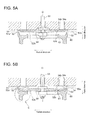
- FIG. 5A is a diagram of the annular valve body 54 and the seat portion 52 in a valve-closed position.
- FIG. 5B is a diagram of the annular valve body 54 and the seat portion 52 in a valve-open position.
- the annular valve according to the present embodiment is applied to the low-pressure valve 50.
- application of the annular valve is not limited to this, and the annular valve may be applied to the high-pressure valve 70.
- the annular valve (low-pressure valve) 50 includes an annular valve seat 51 having a seat portion 52, a rod 53 configured to be movable along a direction orthogonal to the seat portion 52, an annular valve body 54 fixed to the rod 53, and a valve-body moving unit 55 for moving the annular valve body 54 along a direction orthogonal to the seat portion 52.
- the direction orthogonal to the seat portion 52 is substantially equal to the direction along the center axis O of the annular opening 34.
- the annular valve body 54 is disposed so as to face the annular valve seat 51 and fixed to the rod 53.
- the valve-body moving unit 55 is configured to move the annular valve body 54 along the direction orthogonal to the seat portion 52 between a valve-closed position in which the annular valve body 54 contacts the seat portion 52 of the annular valve seat 51 so that the annular opening 34 is closed by the annular valve body 54, and a valve-open position in which the annular valve body 54 is away from the seat portion 52 so that the annular opening 34 is open. Only a portion of the annular valve body 54 that contacts the seat portion 52 may protrude toward the annular valve seat 51 from other part of the annular valve body 54.
- the annular opening 34 is formed on an end of the low-pressure oil inner flow channel 16 that is facing the working chamber 26.
- the seat portion 52 is formed by the outer circumferential edge 34a and the inner circumferential edge 34b of the annular opening 34.
- the seat portion 52 of the annular valve seat 51 is configured to be in surface contact with the annular valve body 54 in the valve-closed position in the first annular region 52a including the outer circumferential edge 34a of the annular opening 34 and the second annular region 52b including the inner circumferential edge 34b of the annular opening 34.
- the annular valve 50 is disposed inside the valve block 30.
- the valve block 30 includes a valve-block body portion 31 on which the annular valve seat 51 is disposed and a valve-block connection portion 32 disposed so as to surround the valve-block body portion 31.
- the valve-block connection portion 32 is fixed to the cylinder block 20, and the valve-block body portion 31 is fixed to the valve-block connection portion 32.
- An intermediate chamber 40 configured to communicate with the working chamber 26 is disposed between the valve-block body portion 31 and the cylinder block 20.
- the intermediate chamber 40 is configured to be capable of communicating with the low-pressure oil inner flow channel 16 and the high-pressure oil inner flow channel 18. Specifically, the low-pressure oil inner flow channel 16 communicates with the intermediate chamber 40 when the annular valve (low-pressure valve) 50 is open, and the high-pressure oil inner flow channel 18 communicates with the intermediate chamber 40 when the high-pressure valve 70 is open.
- the annular valve seat 51 is disposed on a surface of the valve block body portion 31 that is adjacent to the cylinder 22.
- the seat portion 52 of the annular valve seat 51 includes the first annular region 52a including the outer circumferential edge 34a of the annular opening 34 and the second annular region 52b including the inner circumferential edge 34b of the annular opening 34.
- the rod 53 is disposed in a rod hole 33 formed in the valve block body portion 31. An end (hereinafter, referred to as the first end) of the rod 53 protrudes out from the rod hole 33. Further, the rod 53 is configured to be movable along a direction orthogonal to the seat portion (seat surface) 52. As illustrated in the drawing, the annular valve body 54 and the rod 53 may have a relative positional relationship such that the rod 53 is disposed on the center axis O of the annular opening 34 formed on the annular valve body 54, and the rod 53 moves along the center axis O.
- the distance between the seat portion 52 and the rod 53 of the annular valve seat 51 is substantially constant in the circumferential direction, which makes it possible to make the stiffness of the annular valve seat 51 substantially constant in the circumferential direction.
- the relative positional relationship between the rod 53 and the annular valve body 54 is not limited to this, and the rod 53 may be disposed offset from the center axis O of the annular opening 34.
- the annular valve body 54 is disposed so as to face the annular valve seat 51 and fixed to the first end of the rod 53, so as to be capable of moving integrally with the rod 53.
- the annular valve body 54 is disposed in the intermediate chamber 40.
- the valve-body moving unit 55 is configured to move the rod 53 and the annular valve body 54 between the valve-open position and the valve-closed position.
- the valve-body moving unit 55 includes an armature 56 coupled to the second end, which is opposite to the first end, of the rod 53, a biasing member 57 for biasing the armature 56 in a biasing direction, and an electric magnet 58 configured to attract the armature 56 and drive the armature 56 in a direction opposite from the biasing direction when supplied with electric power.
- the valve-body moving unit 55 may be disposed so as to be removable and detachable with respect to the valve block body portion 31.
- annular valve body 54 when the annular valve body 54 is in the valve-closed position, the annular valve body 54 is in surface contact with the first annular region 52a and the second annular region 52b of the seat portion 52.
- the annular valve body 54 when the annular valve body 54 is in the valve-open position, the annular valve body 54 is positioned at a distance from the seat portion 52 so as to be inside a valve-body shroud portion 60 described below.
- the seat portion 52 of the annular valve seat 51 is configured to be in surface contact with the annular valve body 54 in the valve-closed position in the first annular region 52a including the outer circumferential edge 34a of the annular opening 34 and the second annular region 52b including the inner circumferential edge 34b of the annular opening 34.
- the motion of the annular valve body 54 is stabilized by the damping effect achieved by the squeeze film in the surface-contact region between the seat portion 52 and the annular valve body 54, which makes it possible to restrict unstable behaviors of the valve such as delay in the motion of the valve (e.g. delay in closing or opening of the valve) and unintended motion of the valve.
- shock on the annular valve body 54 is reduced due to a decrease in the speed of the annular valve body 54 by the squeeze effect (fluid resistant force), and erosion is restricted in the surface-contact region due to a decrease in the flow speed by formation of a slight planar gap between the seat portion and the annular valve body 54. As a result, it is possible to restrict damage to the annular valve 50.
- the surface-contact region is a region of the seat portion 52 including a surface of the first annular region 52a and a surface of the annular valve body 54 that is in surface contact with the first annular region 52a, and a region of the seat portion 52 including a surface of the second annular region 52b and a surface of the annular valve body 54 that is in surface contact with the second annular region 52b.
- FIG. 6A is a perspective view of the annular valve body 54 according to one embodiment
- FIG. 6B is a side view (cross-sectional view taken along line A-A of FIG. 6A ) of the annular valve body 54 illustrated in FIG. 6A
- FIG. 7A is a perspective view of the annular valve body 54 according to another embodiment
- FIG. 7B is a side view (cross-sectional view taken along line B-B of FIG. 7A ) of the annular valve body 54 illustrated in FIG. 7A .
- the annular valve body 54 includes a valve-body portion 541 that is in surface contact with the first annular region 52a and the second annular region 52b of the seat portion 52 in the valve-closed position, a fixed portion 542 that is fixed to the first end of the rod 53, and a connection portion 543 that couples the valve-body portion 541 and the fixed portion 542.
- connection portion 543 has a spring constant of 9kN/mm or more in a direction along the rod 53.
- the direction along the rod 53 is substantially equal to a direction along the center axis O of the annular opening 34.
- cavitation may occur in the flow of the fluid, and this cavitation may cause unstable behaviors of the annular valve 50.
- connection portion 543 connecting the valve-body portion 541 and the fixed portion 542 is configured to have a spring constant of 9kN/mm or more in a direction along the rod 53.
- a spring constant of 9kN/mm or more in a direction along the rod 53.
- connection portion 543 includes a plurality of connection arms 543a that is disposed at different positions in the circumferential direction and that couples the rod 53 and the valve-body portion 541.
- connection arms 543a are disposed at regular intervals (intervals of 90 degrees) in a radial fashion from the fixed portion 542 at the center.
- connection arm 543a extends linearly so as to bridge over the valve-body portion 541 and the fixed portion 542.
- connection arms for connecting the rod and the valve-body portion is disposed at different positions in the circumferential direction, each extending in a linear fashion.
- the annular valve body 54 faces the annular valve seat 51 (see FIG. 5A or FIG. 5B ) and includes the first surface 545 which is flat and parallel to a radial direction of the annular opening 34 and the second surface 546 disposed opposite to the first surface, the second surface 546 including an inclined region 547 that inclines from the radial direction.
- the second surface is inclined in the radial direction so that the thickness of the annular valve body 54 increases inwardly in the radial direction at the inclined region 547.
- the first surface 545 of the annular valve body 54 is formed flat and parallel to the radial direction of the annular opening 34, it is possible to cause the first surface 545 of the annular valve body 54 to be in surface contact with the first annular region 52a and the second annular region 52b of the seat portion 52 easily.
- the second surface 546 of the annular valve body 54 includes the inclined region 547 that is inclined in the radial direction, and the thickness of the annular valve body 54 increases inwardly in the radial direction at the inclined region 547. In this way, it is possible to improve the stiffness of the annular valve body 54 and restrict the valve-body portion 541 from inclining from the seat portion 52.
- the annular valve body 54 faces the annular valve seat 51 (see FIG. 5A or FIG. 5B ) and includes the first surface 545 which is flat and parallel to a radial direction of the annular opening 34 and the second surface 546 disposed opposite to the first surface, the second surface 546 being flat and parallel to the radial direction of the annular opening. That is, the first surface 545 and the second surface 546 are formed substantially parallel to each other.
- the annular valve 50 further includes a valve-body shroud portion 60 that is disposed so as to be positioned opposite to the annular valve seat 51 across the annular valve body 54 in a direction along the center axis O of the annular opening 34 (hereinafter, referred to as the axial direction).
- the surface facing the annular valve seat 51 is referred to as the first surface 545
- the surface opposite to the first surface 545 is referred to as the second surface 546.
- the valve-body shroud portion 60 is configured to cover the second surface 546 and the outer circumferential surface 548 of the annular valve body 54 in the valve-open position at least partially.
- the valve-body shroud portion 60 includes an annular base portion 61 disposed so as to face the second surface of the annular valve body 54, and a rim portion 62 protruding from the outer circumferential edge of the base portion 61 toward the annular valve seat 51.
- the second surface 546 of the annular valve body 54 is covered by the base portion 61
- the outer circumferential surface 548 of the annular valve body 54 is covered by the rim portion 62.
- the base portion 61 and the rim portion 62 may be formed integrally.
- valve-body shroud portion 60 is disposed so as to cover the second surface 546 and the outer circumferential surface 548 of the annular valve body 54 in the valve-open position at least partially, the annular valve body 54 separated from the annular valve seat 51 is restricted from being forced toward the annular valve seat by the flow of the fluid in the valve-open position. As a result, it is possible to stabilize the motion of the annular valve body 54 regardless of the pressure or flow rate of the fluid.
- FIG. 8 is an enlarged view of section C of FIG. 5B .
- d is a distance in the axial direction between the tip end surface 62a of the rim portion 62 and the surface of the outer circumferential edge portion 549 of the annular valve body 54, which is a distance along the center axis O illustrated in FIG. 5A
- t is the thickness of the outer circumferential edge portion 549 of the annular valve body 54.
- a tapered surface 548a is formed on the outer circumferential surface 548 of the annular valve body 54 as described below, in case of which the thickness of the outer circumferential edge portion 549 may be the thickness of the annular valve body 54 including the tapered surface 548a.
- a gap 63 is formed between the inner circumferential surface 62b of the rim portion 62 and the outer circumferential surface 548 of the annular valve body 54, and the width d of the gap 63 may have a size of 0.005D or more, where D is the outer diameter of the annular valve body 54.
- the outer diameter D is the diameter of the annular valve body 54, as illustrated in FIG. 6B or 7B .
- the width d of the gap represents the distance between the outer circumferential surface 548 of the annular valve body 54 and the inner circumferential surface 62b of the rim portion 62 in the radial direction.
- the gap 63 is formed between the inner circumferential surface 62b of the rim portion 62 and the outer circumferential surface 548 of the annular valve body 54, and the gap 63 has a size of 0.005D or more, where D is the outer diameter of the annular valve body 54.
- D is the outer diameter of the annular valve body 54.
- root portion 62c of the rim portion 62 may be configured such that the thickness of the root portion 62c increases toward the base portion 61.
- the inner circumferential surface 62b has a shape curved into an R shape so as to have a curvature center at a side closer to the annular valve body 54.
- the inner circumferential surface 62b may include a tapered surface that is inclined toward the annular valve body 54 toward the base portion 61.
- the thickness of the root portion 62c of the rim portion 62 increases toward the base portion 61, which makes it possible to secure the strength whereby the flow of the fluid is bearable at the rim portion 62.
- a distance g in the radial direction between the inner circumferential edge 62a1 of the tip end surface 62a of the rim portion 62 and the outer circumferential surface 548 of the annular valve body 54 may increase, from the first surface 545 toward the second surface 546 of the annular valve body 54.
- the gap between the inner circumferential surface of the rim portion 62 and the outer circumferential surface 548 of the annular valve body 54 may become larger with an increase in the amount of lift of the annular valve body 54 from the valve-body shroud portion 60 in a range of motion in the axial direction in which at least a part of the annular valve body 54 is covered by the rim portion 62 during an operation for opening or closing the valve.
- a tapered surface 548a that is inclined inwardly in the radial direction from the first surface 545 toward the second surface 546 is disposed on at least a part of the outer circumferential surface 548 of the annular valve body 54, the part being adjacent to the second surface 546.
- at least a part of the outer circumferential surface 548 of the annular valve body 54 that is adjacent to the second surface 546 may be formed into an R shape.
- the distance g in the radial direction between the rim portion 62 and the annular valve body 54 is configured to increase from the first surface 545 toward the second surface 546 of the annular valve body 54, the fluid smoothly flows in and out between the annular valve body 54 and the valve-body shroud portion 60 while the valve operation is in a transient state, which makes it possible to further improve the response speed of the annular valve body 54.
- a ridge 65 protruding toward the annular valve seat 51 is disposed on the inner circumferential edge of the base portion 61 formed in an annular shape.
- the annular valve body 54 may be configured such that the second surface 546 of the annular valve body 54 contacts the ridge 65 in the valve-open position, and a gap 66 is formed between the base portion 61 and the second surface 546.
- a ridge protruding toward the base portion 61 may be disposed on the second surface 546 of the annular valve body 54.
- the ridge 65 protruding toward the annular valve seat 51 is disposed on the inner circumferential edge of the base portion 61 of the valve-body shroud portion 60. Due to the interposition of the ridge 65, the gap 66 is formed between the base portion 61 and the second surface 546 of the annular valve body 54 in the valve-open position. In this way, the fluid smoothly flows in and out between the annular valve body 54 and the valve-body shroud portion while the valve operation is in a transient state, which makes it possible to further improve the response speed of the annular valve body 54.
- valve-body shroud portion 60 is fixed to the valve block body portion 31 by a support portion 67.
- the annular valve 50 may further include a sieve portion 68 supported by the support portion 67.
- the sieve portion 68 is disposed so as to face the working chamber 26 and configured to prevent foreign matters from entering the working chamber 26.
- the sieve portion 68 is constituted of a perforated plate member.
- the support portion 67, the valve-body shroud portion 60, and the sieve portion 68 may be formed integrally.
- the above described annular valve 50 may further include the following configuration.
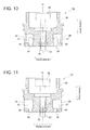
- FIG. 9 is a view of a valve casing 35 of the annular valve 50 according to one embodiment, as seen from the side of the annular opening 34.
- FIG. 10 is a cross-sectional view of the valve casing 35 of the annular valve 50 according to one embodiment, taken along line D-D from FIG. 9 .
- FIG. 11 is a cross-sectional view of the valve casing 35 of the annular valve 50 according to one embodiment, taken along line E-E from FIG. 9 .
- the annular valve 50 further includes the valve casing 35 including the annular valve seat 51.
- the valve casing 35 may be constituted of the valve block body portion 31, or of the valve block body portion 31 and at least a part of the valve block connection portion 32.
- the valve casing 35 includes an annular groove 36 that forms the annular opening 34 and extends from the annular opening 34 along the center axis toward the opposite side from the annular valve body 54, and a plurality of radial flow channels 37 that extends in the radial direction of the annular opening 34 so as to communicate with the annular groove 36.
- the annular groove 36 is formed in an annular shape that is coaxial with the center axis O, extending along the center axis O.
- the annular opening 34 is formed on one end side of the annular groove 36 in the axial direction, and the other end side communicates with the plurality of radial flow channels 37.
- the plurality of radial flow channels 37 is arranged in a radial fashion, centered at the center axis O. An end of each radial flow channel 37 adjacent to the center axis O communicates with the annular groove 36.
- the valve casing 35 includes the annular groove 36 that forms the annular opening 34 and extends along the center axis, and the plurality of radial flow channels 37 that extends in the radial direction of the annular opening 34 so as to communicate with the annular groove 36.
- the annular groove 36 may have a diffuser shape such that the cross-sectional area of the flow path increases with distance from the annular opening 34.
- the width of the annular groove 36 smoothly increases with distance from the annular opening 34.
- the width 36 of the annular groove is a distance between the inner circumferential wall and the outer circumferential wall of the annular groove 36 in the radial direction.
- annular groove 36 has a cross-sectional area of the flow path that increases with distance from the annular opening 34, smooth discharge or introduction of the fluid in the annular valve 50 is enabled.
- valve casing 35 further includes an annular flow channel 38 that is disposed radially outside the plurality of radial flow channels 37 and communicates with the plurality of radial flow channels 37.
- the area of the cross section of the annular flow channel 38 orthogonal to the center axis O may be equal to or more than the area of the opening of the annular opening 34.
- the annular flow channel 38 is disposed radially outside the annular groove 36 at which the annular opening 34 is formed.
- valve casing 35 includes the annular flow channel 38 communicating with the plurality of radial flow channels 37, and the area of the cross section of the annular flow channel orthogonal to the center axis O is equal to or more than the area of the opening of the annular opening 34, smooth discharge or introduction of the fluid in the annular valve 50 is enabled.
- the area of the cross section of the flow path of each of the radial flow channels 37 may be 1/4 or more of the area of the cross section of the annular flow channel 38 orthogonal to the center axis O.
- valve casing 35 includes the annular flow channel 38 communicating with the plurality of radial flow channels 37, and the area of cross section of the flow path of each of the plurality of radial flow channels 37 is 1/4 or more of the area of the cross section of the annular flow channel 38 orthogonal to the center axis O, smooth discharge or introduction of the fluid in the annular valve 50 is enabled.
- the low-pressure valve 50 of the hydraulic motor 7 it is important to discharge low-pressure working oil after having performed work smoothly.
- the low-pressure working oil flows through the annular opening 34, the annular groove 36, the radial flow channels 37, and the annular flow channel 38 in this order.
- the area of cross section of the flow path being larger toward the downstream side, it is possible to discharge the working oil from the working chamber 26 (see FIGs. 3 and 4 ) smoothly.
- the high-pressure valve 70 may further include the following configuration.
- the high-pressure valve 70 is the annular valve 50 disposed adjacently to the low-pressure valve 50, including an annular valve seat 71, a rod 73, an annular valve body 74, and a valve-body moving unit 75.
- the valve block 30 includes a high-pressure inner flow channel 18d that has a donut shape surrounding the periphery of the high-pressure valve 70, so that high-pressure working oil flows into the intermediate chamber 40 from the high-pressure inner flow channel 18d when the high-pressure valve 70 is open.
- the high-pressure valve 70 may have configuration similar to that of the above described annular valve (low-pressure valve) 50 selectively.
- the present invention it is possible to restrict unstable behaviors of the annular valve 50 such as delay in the motion (e.g. delay in opening or closing) of the annular valve 50 and unintended motion, and to restrict damage to the annular valve 50.
- a trouble of the annular valve 50 is less likely to occur in at least one of the hydraulic pump 6 or the hydraulic motor 7, which enables stable operation of the power generating apparatus of renewable-energy type 1.
- an expression of relative or absolute arrangement such as “in a direction”, “along a direction”, “parallel”, “orthogonal”, “centered”, “concentric” and “coaxial” shall not be construed as indicating only the arrangement in a strict literal sense, but also includes a state where the arrangement is relatively displaced by a tolerance, or by an angle or a distance whereby it is possible to achieve the same function.
- an expression of an equal state such as “same” “equal” and “uniform” shall not be construed as indicating only the state in which the feature is strictly equal, but also includes a state in which there is a tolerance or a difference that can still achieve the same function.
- an expression of a shape such as a rectangular shape or a cylindrical shape shall not be construed as only the geometrically strict shape, but also includes a shape with unevenness or chamfered corners within the range in which the same effect can be achieved.
Landscapes
- Engineering & Computer Science (AREA)
- General Engineering & Computer Science (AREA)
- Mechanical Engineering (AREA)
- Lift Valve (AREA)
- Valve Housings (AREA)
- Magnetically Actuated Valves (AREA)
- Wind Motors (AREA)
Abstract
Description
- The present disclosure relates to an annular valve and a power generating apparatus of renewable-energy type.
- Generally, an annular valve for opening and closing a flow channel formed in an annular shape is known. An annular valve is disposed in an annular hydraulic flow channel communicating with a working chamber in a hydraulic machine, for instance, and configured to be opened and closed so as to control inflow and outflow of working oil with respect to the working chamber.
- For instance,
Patent Documents 1 to 4 disclose an annular valve including a rod, a valve body configured to be movable along with the rod, and a valve seat configured such that the valve body is capable of contacting the valve seat at radially inside and outside of an annular opening. - In such an annular valve, the contacting surface between the valve body and the valve seat in the seating position has an annular shape at each of the radially inner side and the radially outer side of the annular opening. Thus, to enable secure closure of the annular opening when the valve is to be closed, at least one of the valve body or the valve seat normally includes a sealing ridge (radially-outer sealing ridge and radially-inner sealing ridge) where the cross section of the contacting surface is curved so that a middle portion in the radial direction of the contacting surface having an annular shape protrudes toward the other one of the valve body or the valve seat.
-
- Patent Document 1:
WO2010/057494A - Patent Document 2:
WO2010/073040A - Patent Document 3:
US2011/0220230A - Patent Document 4:
WO2013/118182A - In the above described annular valve, if the flow rate in the annular flow channel is large, unstable behaviors may occur, such as delay in motion of the valve (e.g. delay in closure or opening of the valve) and unintended motion of the valve. Further, due to the unstable behaviors of the valve or the flow of fluid, the valve may get damaged. Especially in an annular valve of a large size, the flow rate of fluid flowing through the annular flow channel is large, which increases the risk of unstable behaviors of the valve or damage to the valve. Thus, conventional designs may fail to provide sufficient performance.
- An object of at least some embodiments of the present invention is to provide an annular valve and a power generating apparatus of renewable-energy type whereby it is possible to restrict unstable behaviors of the valve and damage to the valve.
- (1) An annular valve according to at least some embodiments of the present invention includes: an annular valve seat including a seat portion formed by an outer circumferential edge and an inner circumferential edge of an annular opening; a rod configured to be movable along a direction orthogonal to the seat portion; an annular valve body disposed so as to face the annular valve seat and fixed to the rod; and a valve-body moving unit for moving the annular valve body between: a valve-closed position in which the annular valve body contacts the seat portion of the annular valve seat so that the annular opening is closed by the annular valve body; and a valve-open position in which the annular valve body is positioned away from the seat portion of the annular valve seat so that the annular opening is open.
- The seat portion of the annular valve seat is configured to be in surface contact with the annular valve body in the valve-closed position in a first annular region including the outer circumferential edge of the annular opening and in a second annular region including the inner circumferential edge of the annular opening.
- In the above annular valve (1), the seat portion of the annular valve seat is configured to be in surface contact with the annular valve body in the valve-closed position in the first annular region including the outer circumferential edge of the annular opening and the second annular region including the inner circumferential edge of the annular opening.
- Thus, during an operation for opening or closing the annular valve, the motion of the annular valve body is stabilized by the damping effect achieved by the squeeze film in the surface-contact region between the seat portion and the annular valve body, which makes it possible to restrict unstable behaviors of the valve such as delay in the motion of the valve (e.g. delay in closing or opening of the valve) and unintended motion of the valve.
- Further, during an operation for opening or closing the annular valve, shock on the annular valve body is reduced due to a decrease in the speed of the annular valve body by the squeeze effect (fluid resistant force), and erosion is restricted in the surface-contact region due to a decrease in the flow speed by formation of a slight planar gap between the seat portion and the annular valve body. As a result, it is possible to restrict damage to the annular valve.
- The surface-contact region is a region of the seat portion including a surface of the first annular region and a surface of the annular valve body that is in surface contact with the first annular region, and a region of the seat portion including a surface of the second annular region and a surface of the annular valve body that is in surface contact with the second annular region.
- (2) In some embodiments, in the above configuration (1), the annular valve body includes: a valve-body portion which is in surface contact with the first annular region and the second annular region of the seat portion in the valve-closed position; a fixed portion fixed to the rod; and a connection portion which connects the valve-body portion and the fixed portion, the connection portion having a spring constant of 9kN/mm or more in a direction along the rod.
- Generally, during an operation for opening or closing the annular valve, cavitation may occur in the flow of the fluid, and this cavitation may cause unstable behaviors of the annular valve.
- As a result of intensive research of the present inventors, it was found that one of the reasons for occurrence of cavitation is the unevenness in the flow of the fluid around the annular valve during an operation for opening or closing the valve. Specifically, when the flow of the fluid around the annular valve becomes uneven, the valve-body portion may incline from the seat portion due to a pressure differential of the fluid flowing through the annular opening. As a result, during an operation for opening or closing the valve, only a part of the valve-body portion in the circumferential direction may contact the seat portion, and the other portion may become out of contact. In this state, a gap is formed at the noncontact section between the valve-body portion and the seat portion. Thus, a jet stream may be created in this gap and cavitation may occur in the fluid.
- In view of this, in the above configuration (2), the connection portion connecting the valve-body portion and the fixed portion is configured to have a spring constant of 9kN/mm or more in a direction along the rod. In this way, it is possible to improve the stiffness of the annular valve body and restrict the valve-body portion from inclining from the seat portion. Thus, during an operation for opening or closing the valve, it is possible to avoid an event such that the valve-body portion and the seat portion become partially out of contact to form a gap through which a jet stream flows to cause cavitation. As a result, it is possible to restrict unstable behaviors of the annular valve due to occurrence of cavitation.
- (3) In one embodiment, in the above configuration (2), the connection portion includes a plurality of connection arms connecting the fixed portion and the valve-body portion, the connection arms being disposed at different positions in a circumferential direction, and each of the plurality of connection arms extends linearly.
- With the above configuration (3), the plurality of connection arms for connecting the fixed portion and the valve-body portion is disposed at different positions in the circumferential direction, each extending in a linear fashion. Thus, it is possible to further enhance the stiffness of the annular valve body and to prevent occurrence of cavitation effectively.
- (4) In some embodiments, in any one of the above configurations (1) to (3), the annular valve body includes a first surface facing the annular valve seat and a second surface disposed opposite to the first surface, and the annular valve body further includes a valve-body shroud portion disposed opposite to the annular valve seat across the annular valve body in an axial direction of the annular opening, the valve-body shroud portion being configured to cover the second surface and an outer circumferential surface of the annular-valve body at least partially in the valve-open position.
- With the above configuration (4), since the valve-body shroud portion is disposed so as to cover the second surface (which does not face the annular valve seat) and the outer circumferential surface of the annular valve body in the valve-open position at least partially, the annular valve body separated from the annular valve seat is restricted from being forced toward the annular valve seat by the flow of the fluid in the valve-open state (in which the annular valve body is in the valve-open position). As a result, it is possible to stabilize the motion of the annular valve body regardless of the pressure or flow rate of the fluid.
- (5) In some embodiments, in the above configuration (4), the valve-body shroud portion includes: a base portion having an annular shape and being disposed so as to face the second surface of the annular valve body; and a rim portion protruding toward the annular valve seat from an outer circumferential edge of the base portion, and a relationship of d ≤ 0.05t is satisfied when the annular valve body is in the valve-open position, where d is a distance between a tip end surface of the rim portion and a surface of the annular valve body at an outer circumferential edge portion, along a center axis of the annular opening, and t is a thickness of the annular valve body at the outer circumferential edge portion.
- In the above configuration (5), the second surface of the annular valve body is covered by the base portion, and the outer circumferential surface of the annular valve body is covered by the rim portion. Further, when the annular valve body is in the valve-open position, a relationship of d≤0.05t is satisfied, where d is a distance between the tip end surface of the rim portion and the surface of the outer circumferential edge portion of the annular valve body, and t is the thickness of the outer circumferential edge portion of the annular valve body. Specifically, when the annular valve body is in the valve-open position, a substantial part or the entire part of the outer circumferential surface of the annular valve body is covered by the rim portion. In this way, in the valve-open state, it is possible to protect the annular valve body from the flow of the fluid effectively, and to further stabilize the motion of the annular valve body.
- (6) In one embodiment, in the above configuration (4) or (5), the valve-body shroud portion includes: a base portion having an annular shape and being disposed so as to face the second surface of the annular valve body; and a rim portion protruding toward the annular valve seat from an outer circumferential edge of the base portion. A gap is formed between an inner circumferential surface of the rim portion and an outer circumferential surface of the annular valve body when the annular valve body is in the valve-open position. The gap has a size of 0.005D or more, where D is an outer diameter of the annular valve body.
- With the above configuration (6), a gap is formed between the inner circumferential surface of the rim portion and the outer circumferential surface of the annular valve body, and the gap has a size of 0.005D or more, where D is the outer diameter of the annular valve body. In this way, the fluid flows in and out smoothly between the annular valve body and the valve-body shroud portion via the gap, which makes it possible to reduce the influence of the back pressure of the annular valve body during an operation for opening or closing the valve and to improve the response speed of the annular valve body.
- (7) In some embodiments, in any one of the above configurations (4) to (6), the valve-body shroud portion includes: a base portion having an annular shape and being disposed so as to face the second surface of the annular valve body; and a rim portion protruding toward the annular valve seat from an outer circumferential edge of the base portion, and a root portion of the rim portion is configured such that a thickness of the root portion increases toward the base portion.
- With the above configuration (7), the thickness of the root portion of the rim portion increases toward the base portion, which makes it possible to secure the strength whereby the flow of the fluid is bearable at the rim portion.
- (8) In some embodiments, in any one of the above configurations (4) to (7), the valve-body shroud portion includes: a base portion having an annular shape and being disposed so as to face the second surface of the annular valve body; and a rim portion protruding toward the annular valve seat from an outer circumferential edge of the base portion, and a distance in a radial direction between an inner circumferential edge of a tip end surface of the rim portion and the outer circumferential surface of the annular valve body increases toward the second surface from the first surface of the annular valve body.
- With the above configuration (8), a distance in the radial direction between the inner circumferential edge of the tip end surface of the rim portion and the outer circumferential surface of the annular valve body increases, from the first surface toward the second surface of the annular valve body. Specifically, the gap between the inner circumferential surface of the rim portion and the outer circumferential surface of the annular valve body becomes larger with an increase in the amount of lift of the annular valve body from the valve-body shroud portion in a range of motion in the axial direction in which at least a part of the annular valve body is covered by the rim portion during an operation for opening or closing the valve. In this way, the fluid smoothly flows in and out between the annular valve body and the valve-body shroud portion while the valve operation is in a transient state, which makes it possible to further improve the response speed of the annular valve body.
- (9) In some embodiments, in any one of the above configurations (4) to (8), the valve-body shroud portion includes: a base portion having an annular shape and being disposed so as to face the second surface of the annular valve body; and a rim portion protruding toward the annular valve seat from an outer circumferential edge of the base portion. A ridge protruding toward the annular valve seat is disposed on an inner circumferential edge of the base portion. The second surface of the annular valve body contacts the ridge in the valve-open position and a gap is formed between the base portion and the second surface.
- With the above configuration (9), the ridge protruding toward the annular valve seat is disposed on the inner circumferential edge of the base portion of the valve-body shroud portion. Due to the interposition of the ridge, a gap is formed between the base portion and the second surface of the annular valve body in the valve-open position. In this way, the fluid smoothly flows in and out between the annular valve body and the valve-body shroud portion while the valve operation is in a transient state, which makes it possible to further improve the response speed of the annular valve body.
- (10) In some embodiments, in any one of the above configurations (1) to (9), the annular valve body includes: a first surface facing the annular valve seat, the first surface being flat and parallel to a radial direction of the annular opening; and a second surface disposed opposite to the first surface, the second surface including an inclined region which inclines with respect to the radial direction. The second surface is inclined with respect to the radial direction in the inclined region so that a thickness of the annular valve body increases inwardly in the radial direction.
- With the above configuration (10), since the first surface of the annular valve body is formed flat and parallel to the radial direction of the annular opening, it is possible to cause the first surface of the annular valve body to be in surface contact with the first annular region and the second annular region of the seat portion easily. Further, the second surface of the annular valve body includes the inclined region that is inclined in the radial direction, and the thickness of the annular valve body increases inwardly in the radial direction at the inclined region. In this way, it is possible to improve the stiffness of the annular valve body and restrict inclination of the valve-body portion from the seat portion. Thus, during an operation for opening or closing the valve, it is possible to avoid an event such that the valve-body portion and the seat portion become partially out of contact to form a gap through which a jet stream flows to cause cavitation. As a result, it is possible to restrict unstable behaviors of the annular valve due to occurrence of cavitation.
- (11) In some embodiments, in any one of the above configurations (1) to (10), the annular valve further includes a valve casing including the annular valve seat. The valve casing includes: an annular groove forming the annular opening and extending from the annular opening along a center axis of the annular opening toward a side opposite from the annular valve body; and a plurality of radial flow channels extending along a radial direction of the annular opening so as to communicate with the annular groove.
- With the above configuration (11), the valve casing includes the annular groove that forms the annular opening and extends along the center axis, and the plurality of radial flow channels that extends along the radial direction of the annular opening so as to communicate with the annular groove. Thus, it is possible to secure a space for placing the valve-body moving unit (e.g. electric magnet) securely around the end portion of the rod on a side opposite to where the annular valve body is fixed.
- (12) In one embodiment, in the above configuration (11), the annular groove has a diffuser shape such that a cross-sectional area of a flow path increases with distance from the annular opening.
- With the above configuration (12), since the annular groove has a cross-sectional area of the flow path that increases with distance from the annular opening, smooth discharge or introduction of the fluid in the annular valve is enabled.
- (13) In one embodiment, in the above configuration (11) or (12), the valve casing further includes an annular flow channel disposed radially outside the plurality of radial flow channels, the annular flow channel communicating with the plurality of radial flow channels. An area of a cross section of the annular flow channel, the cross section being orthogonal to the center axis, is not less than an opening area of the annular opening.
- With the above configuration (13), since the valve casing includes the annular flow channel communicating with the plurality of radial flow channels, and the area of the cross section of the annular flow channel orthogonal to the center axis is equal to or more than the area of the opening of the annular opening, smooth discharge or introduction of the fluid in the annular valve is enabled.
- (14) In one embodiment, in any one of the above configurations (11) to (13), the valve casing further includes an annular flow channel disposed radially outside the plurality of radial flow channels, the annular flow channel communicating with the plurality of radial flow channels, and a cross-sectional area of a path of each of the plurality of radial flow channels is not less than 1/4 times an area of a cross section of the annular flow channel, the cross section being orthogonal to the center axis.
- With the above configuration (14), since the valve casing includes the annular flow channel communicating with the plurality of radial flow channels, and the area of cross section of the flow path of each of the plurality of radial flow channels is 1/4 or more of the area of the cross section of the annular flow channel orthogonal to the center axis, smooth discharge or introduction of the fluid in the annular valve is enabled.
- A power generating apparatus of renewable-energy type according to at least some embodiments includes: a rotor configured to rotate by receiving renewable energy; a hydraulic pump configured to be driven by the rotor to increase a pressure of working fluid; a hydraulic motor configured to be driven by the working fluid; and a generator configured to be driven by the hydraulic motor. At least one of the hydraulic pump or the hydraulic motor includes: a working chamber formed by a cylinder and a piston which is reciprocable in the cylinder; an inner flow channel configured to be capable of bringing the working chamber into communication with an outer flow channel disposed between the hydraulic pump and the hydraulic motor; and the annular valve according to any one of the above configurations (1) to (14) disposed in the inner flow channel and configured to be capable of switching a communication state between the working chamber and the outer flow channel.
- In the above power generating apparatus of renewable-energy type (15), at least one of the hydraulic pump or the hydraulic motor is the annular valve according to the above (1) to (14). As described above, since the annular valve enables restriction of unstable behaviors of the valve and damage to the valve, a trouble of the annular valve is less likely to occur in at least one of the hydraulic pump or the hydraulic motor, which enables stable operation of the power generating apparatus of renewable-energy type.
- According to at least some embodiments of the present invention, it is possible to restrict unstable behaviors of the annular valve such as delay in the motion (e.g. delay in opening or closing) of the annular valve and unintended motion, and to restrict damage to the annular valve.
-
-
FIG. 1 is an overall configuration diagram of a wind turbine generator according to one embodiment. -
FIG. 2 is a cross-sectional view of a schematic configuration of a hydraulic machine according to one embodiment. -
FIG. 3 is a cross-sectional view of a low-pressure valve and a high-pressure valve with the peripheral structure thereof according to one embodiment. -
FIG. 4 is a cross-sectional view of a low-pressure valve and the peripheral structure thereof according to one embodiment. -
FIG. 5A is a diagram of an annular valve body and a seat portion in a valve-closed position.FIG. 5B is a diagram of an annular valve body and a seat portion in a valve-open position. -
FIG. 6A is a perspective view of an annular valve according to one embodiment.FIG. 6B is a cross-sectional view of the annular valve body illustrated inFIG. 6A , taken along line A-A. -
FIG. 7A is a perspective view of an annular valve body according to another embodiment.FIG. 7B is a cross-sectional view of the annular valve body illustrated inFIG. 7A , taken along line A-A. -
FIG. 8 is a partial cross-sectional view of an annular valve body and a seat portion according to one embodiment (an enlarged view of section C ofFIG. 5B ). -
FIG. 9 is a view of a valve casing of an annular valve according to one embodiment, as seen from the side of an annular opening. -
FIG. 10 is a cross-sectional view of the valve casing of the annular valve according to one embodiment, taken along line D-D fromFIG. 9 . -
FIG. 11 is a cross-sectional view of the valve casing of the annular valve according to one embodiment, taken along line E-E fromFIG. 9 . - Embodiments of the present invention will now be described in detail with reference to the accompanying drawings. It is intended, however, that unless particularly specified, dimensions, materials, shapes, relative positions and the like of components described in the embodiments shall be interpreted as illustrative only and not limitative of the scope of the present invention.
-
FIG. 1 is an overall configuration diagram of a wind turbine generator according to one embodiment. - In the following description, a
wind turbine generator 1 which is a power generating apparatus of renewable-energy type is described as an example of an object to which an annular valve according to the present embodiment is applied. However, application of the annular valve according to the present embodiment is not limited to this, and may be a power generating apparatus of renewable-energy type of another kind, or an apparatus other than a power generating apparatus of renewable-energy type such as an industrial vehicle, an industrial machine, a ship device, and the like. - As illustrated in
FIG. 1 , thewind turbine generator 1 according to one embodiment includes arotor 5 including at least oneblade 2, ahub 3 to which the at least oneblade 2 is mounted, and arotation shaft 4 configured to be rotatable integrally with thehub 3. Therotor 5 is supported rotatably to anacelle 12 via a main bearing, and configured to rotate as the at least oneblade 2 receives wind. Thenacelle 12 is mounted to an upper end portion of atower 13 disposed on ocean or on land. - A
hydraulic pump 6 is connected to therotor 5 via therotation shaft 4. Ahydraulic motor 7 is connected to thehydraulic pump 6 via a high-pressure oil line 8 and a low-pressure oil line 9. Specifically, an outlet of thehydraulic pump 6 is connected to an inlet of thehydraulic motor 7 via the high-pressure oil line 8, and an inlet of thehydraulic pump 6 is connected to an outlet of thehydraulic motor 7 via the low-pressure oil line 9. Thehydraulic pump 6 is configured to be driven by therotor 5 to increase the pressure of working oil, thereby producing high-pressure working oil (pressurized oil). The pressurized oil produced by thehydraulic pump 6 is supplied to thehydraulic motor 7 via the high-pressure oil line 8. Thehydraulic motor 7 is configured to be driven by the pressurized oil whose pressure is increased by thehydraulic pump 6. The low-pressure working oil having performed work in thehydraulic motor 7 is returned again to thehydraulic pump 6 via the low-pressure oil line 9 disposed between the outlet of thehydraulic motor 7 and the inlet of thehydraulic pump 6. Agenerator 10 is connected to thehydraulic motor 7 via anoutput shaft 11. Thegenerator 10 is configured to be driven by thehydraulic motor 7 and to generate electric power. -
FIG. 2 is a cross-sectional view of schematic configuration of ahydraulic machine 7 according to one embodiment. - While a hydraulic motor is illustrated in
FIG. 2 as thehydraulic machine 7, a hydraulic machine to which the present embodiment is to be applied is not limited to this, and may be a hydraulic pump. - In some embodiments, the
hydraulic machine 7 includes a working chamber 26 formed by a cylinder 22 and apiston 24,inner flow channels pressure oil line 8 or the low-pressure oil line 9 inFIG. 1 ) disposed between thehydraulic pump 6 and thehydraulic motor 7 into communication, and an annular valve (e.g. a low-pressure valve 50 or a high-pressure valve 70) disposed in theinner flow channels - The
rotation shaft 14 is coupled to the output shaft 11 (seeFIG. 1 ) in a case of thehydraulic motor 7, and to the rotation shaft 4 (seeFIG. 1 ) in the case of thehydraulic pump 6. - A
cylinder block 20 extends in annular shape over the entire periphery of therotation shaft 14, and includes a plurality of cylinders 22 extending in a radial direction from arotational axis 15 of therotation shaft 14 at the center, a plurality ofpistons 24 disposed so as to be reciprocable in the respective cylinders 22, and working chambers 26 formed by the cylinders 22 and thepistons 24. - A plurality of valve blocks 30 is disposed outside the
cylinder block 20 in the radial direction, corresponding to the positions of the cylinders 22. Eachvalve block 30 includes the low-pressure valve 50 and the high-pressure valve 70. - In the
cylinder block 20 and the valve blocks 30, high-pressure oilinner flow channels 18 connected to the high-pressure oil line 8 (seeFIG. 1 ) and low-pressure oilinner flow channels 16 connected to the low-pressure oil line 9 are formed. Each of the high-pressure oilinner flow channels 18 and the low-pressure oilinner flow channels 16 is connected to corresponding one of the working chambers 26. The communication state between each high-pressure oilinner flow channel 18 and the working chamber 26 is switched by opening and closing the high-pressure valve 70 disposed in the high-pressure oilinner flow channel 18. The communication state between each low-pressure oilinner flow channel 16 and the working chamber 26 is switched by opening and closing the low-pressure valve 50 disposed in the low-pressure oilinner flow channel 16. - In the
hydraulic machine 7, as a result of the switching between the low-pressure valve 50 and the high-pressure valve 70, working oil flows into and out from the working chamber 26, so that the pressure energy of the working oil in the working chamber 26 is converted into the reciprocating-motion energy of thepiston 24 or vice versa, and the reciprocating-motion energy of thepiston 24 is converted into the rotational energy of therotation shaft 14 or vice versa. For instance, in thehydraulic pump 6, the low-pressure valve 50 and the high-pressure valve 70 are switched suitably so as to produce high-pressure working oil using the rotational energy of the rotation shaft 4 (seeFIG. 1 ). In thehydraulic motor 7, the low-pressure valve 50 and the high-pressure valve 70 are switched suitably so as to rotate the output shaft 11 (seeFIG. 1 ) using the pressure energy of the high-pressure working oil. - In the present embodiment, at least one of the low-
pressure valve 50 or the high-pressure valve 70 has the following configuration of an annular valve. - Now, as an example of a hydraulic machine, the
hydraulic motor 7 will be described specifically. - In one embodiment, the
hydraulic motor 7 includes therotation shaft 14 coupled to the output shaft 11 (seeFIG. 1 ), thecylinder block 20 disposed radially outside therotation shaft 14, and the valve blocks 30 disposed radially outside thecylinder block 20. - The
hydraulic motor 7 includes acam shaft 14 which has eccentric cams arranged in a plurality of rows in a direction along therotational axis 15, thecam shaft 14 serving as therotation shaft 14. - The
cylinder block 20 extends in an annular shape over the entire circumference of thecam shaft 14. Thecylinder block 20 may be constituted of a plurality of sections arranged in the circumferential direction and connected to one another. Further, thecylinder block 20 includes the plurality of cylinders 22 extending in a radial direction from therotational axis 15 of therotation shaft 14 at the center, the plurality ofpistons 24 disposed so as to be reciprocable in the respective cylinders 22, and the working chambers 26 formed by the cylinders 22 and thepistons 24. In the illustrated example, six cylinders 22 and sixpistons 24 are arranged in the circumferential direction. - A plurality of valve blocks 30 is disposed outside the
cylinder block 20 in the radial direction, corresponding to the positions of the cylinders 22. In the illustrated example, six valve blocks 30 are arranged in the circumferential direction. The valve blocks 30 are fixed to thecylinder block 20 by bolts or the like. - In each of the
cylinder block 20 and the valve blocks 30, a high-pressure oilinner flow channel 18 connected to the high-pressure oil line 8 (seeFIG. 1 ) and a low-pressure oilinner flow channel 16 connected to the low-pressure oil line 9 (seeFIG. 1 ) are formed. Specifically, the high-pressure oilinner flow channel 18a formed inside thecylinder block 20 and the high-pressure oilinner flow channel 18b formed inside thevalve block 30 are connected via thehigh pressure port 18c of thecylinder block 20. Further, the low-pressure oilinner flow channel 16a formed inside thecylinder block 20 and the low-pressure oil inner flow channel 16b formed inside thevalve block 30 are connected via thelow pressure port 16c of thecylinder block 20. - A low-
pressure oil accumulator 17 which is to be connected to the low-pressure oil inner flow channel 16b may be attached to the valve blocks 30 for the purpose of restricting pulsation of the low-pressure oil, for instance. - In the
hydraulic motor 7 having the above configuration, when high-pressure working oil is supplied to the working chamber 26 via the high-pressure oilinner flow channel 18 while the high-pressure valve 70 is open and the low-pressure valve 50 is closed, thepiston 24 reciprocates in the cylinder 22 due to the pressure energy of the working oil, and therotation shaft 14 rotates in accordance with the reciprocating motion of thepiston 24. Then, the working oil having a reduced pressure is discharged from the working chamber 26 into the low-pressure oilinner flow channel 16 by closing the high-pressure valve 70 and opening the low-pressure valve 50. - In the present embodiment, at least one of the low-
pressure valve 50 or the high-pressure valve 70 is constituted by the annular valve described below. - Next, with reference to
FIGs. 3 ,4 ,5A and 5B , the above low-pressure valve 50 or the high-pressure valve 70 and the peripheral structure thereof will be described specifically. -
FIG. 3 is a cross-sectional view of the low-pressure valve 50 and the high-pressure valve 70 with the peripheral structure thereof according to one embodiment.FIG. 4 is a cross-sectional view of the low-pressure valve 50 and the peripheral structure thereof according to one embodiment.FIG. 5A is a diagram of theannular valve body 54 and theseat portion 52 in a valve-closed position.FIG. 5B is a diagram of theannular valve body 54 and theseat portion 52 in a valve-open position. - In the illustrated examples, the annular valve according to the present embodiment is applied to the low-
pressure valve 50. However, application of the annular valve is not limited to this, and the annular valve may be applied to the high-pressure valve 70. - In one embodiment, the annular valve (low-pressure valve) 50 includes an
annular valve seat 51 having aseat portion 52, arod 53 configured to be movable along a direction orthogonal to theseat portion 52, anannular valve body 54 fixed to therod 53, and a valve-body moving unit 55 for moving theannular valve body 54 along a direction orthogonal to theseat portion 52. In the illustrated examples, the direction orthogonal to theseat portion 52 is substantially equal to the direction along the center axis O of theannular opening 34. - The
annular valve body 54 is disposed so as to face theannular valve seat 51 and fixed to therod 53. - The valve-
body moving unit 55 is configured to move theannular valve body 54 along the direction orthogonal to theseat portion 52 between a valve-closed position in which theannular valve body 54 contacts theseat portion 52 of theannular valve seat 51 so that theannular opening 34 is closed by theannular valve body 54, and a valve-open position in which theannular valve body 54 is away from theseat portion 52 so that theannular opening 34 is open. Only a portion of theannular valve body 54 that contacts theseat portion 52 may protrude toward theannular valve seat 51 from other part of theannular valve body 54. - The
annular opening 34 is formed on an end of the low-pressure oilinner flow channel 16 that is facing the working chamber 26. - The
seat portion 52 is formed by the outercircumferential edge 34a and the innercircumferential edge 34b of theannular opening 34. Theseat portion 52 of theannular valve seat 51 is configured to be in surface contact with theannular valve body 54 in the valve-closed position in the firstannular region 52a including the outercircumferential edge 34a of theannular opening 34 and the secondannular region 52b including the innercircumferential edge 34b of theannular opening 34. - As for a specific configuration example, the
annular valve 50 is disposed inside thevalve block 30. Thevalve block 30 includes a valve-block body portion 31 on which theannular valve seat 51 is disposed and a valve-block connection portion 32 disposed so as to surround the valve-block body portion 31. The valve-block connection portion 32 is fixed to thecylinder block 20, and the valve-block body portion 31 is fixed to the valve-block connection portion 32. Anintermediate chamber 40 configured to communicate with the working chamber 26 is disposed between the valve-block body portion 31 and thecylinder block 20. Theintermediate chamber 40 is configured to be capable of communicating with the low-pressure oilinner flow channel 16 and the high-pressure oilinner flow channel 18. Specifically, the low-pressure oilinner flow channel 16 communicates with theintermediate chamber 40 when the annular valve (low-pressure valve) 50 is open, and the high-pressure oilinner flow channel 18 communicates with theintermediate chamber 40 when the high-pressure valve 70 is open. - The
annular valve seat 51 is disposed on a surface of the valveblock body portion 31 that is adjacent to the cylinder 22. Theseat portion 52 of theannular valve seat 51 includes the firstannular region 52a including the outercircumferential edge 34a of theannular opening 34 and the secondannular region 52b including the innercircumferential edge 34b of theannular opening 34. - The
rod 53 is disposed in arod hole 33 formed in the valveblock body portion 31. An end (hereinafter, referred to as the first end) of therod 53 protrudes out from therod hole 33. Further, therod 53 is configured to be movable along a direction orthogonal to the seat portion (seat surface) 52. As illustrated in the drawing, theannular valve body 54 and therod 53 may have a relative positional relationship such that therod 53 is disposed on the center axis O of theannular opening 34 formed on theannular valve body 54, and therod 53 moves along the center axis O. In this case, the distance between theseat portion 52 and therod 53 of theannular valve seat 51 is substantially constant in the circumferential direction, which makes it possible to make the stiffness of theannular valve seat 51 substantially constant in the circumferential direction. However, the relative positional relationship between therod 53 and theannular valve body 54 is not limited to this, and therod 53 may be disposed offset from the center axis O of theannular opening 34. - The
annular valve body 54 is disposed so as to face theannular valve seat 51 and fixed to the first end of therod 53, so as to be capable of moving integrally with therod 53. In the illustrated example, theannular valve body 54 is disposed in theintermediate chamber 40. - As illustrated in
FIG. 4 , the valve-body moving unit 55 is configured to move therod 53 and theannular valve body 54 between the valve-open position and the valve-closed position. For instance, in a case where theannular valve 50 is a solenoid valve, the valve-body moving unit 55 includes anarmature 56 coupled to the second end, which is opposite to the first end, of therod 53, a biasingmember 57 for biasing thearmature 56 in a biasing direction, and anelectric magnet 58 configured to attract thearmature 56 and drive thearmature 56 in a direction opposite from the biasing direction when supplied with electric power. The valve-body moving unit 55 may be disposed so as to be removable and detachable with respect to the valveblock body portion 31. - As illustrated in
FIG. 5A , when theannular valve body 54 is in the valve-closed position, theannular valve body 54 is in surface contact with the firstannular region 52a and the secondannular region 52b of theseat portion 52. - As illustrated in
FIG. 5B , when theannular valve body 54 is in the valve-open position, theannular valve body 54 is positioned at a distance from theseat portion 52 so as to be inside a valve-body shroud portion 60 described below. - With the above configuration, the
seat portion 52 of theannular valve seat 51 is configured to be in surface contact with theannular valve body 54 in the valve-closed position in the firstannular region 52a including the outercircumferential edge 34a of theannular opening 34 and the secondannular region 52b including the innercircumferential edge 34b of theannular opening 34. - Thus, during an operation for opening or closing the
annular valve 50, the motion of theannular valve body 54 is stabilized by the damping effect achieved by the squeeze film in the surface-contact region between theseat portion 52 and theannular valve body 54, which makes it possible to restrict unstable behaviors of the valve such as delay in the motion of the valve (e.g. delay in closing or opening of the valve) and unintended motion of the valve. - Further, during an operation for opening or closing the
annular valve 50, shock on theannular valve body 54 is reduced due to a decrease in the speed of theannular valve body 54 by the squeeze effect (fluid resistant force), and erosion is restricted in the surface-contact region due to a decrease in the flow speed by formation of a slight planar gap between the seat portion and theannular valve body 54. As a result, it is possible to restrict damage to theannular valve 50. - The surface-contact region is a region of the
seat portion 52 including a surface of the firstannular region 52a and a surface of theannular valve body 54 that is in surface contact with the firstannular region 52a, and a region of theseat portion 52 including a surface of the secondannular region 52b and a surface of theannular valve body 54 that is in surface contact with the secondannular region 52b. -
FIG. 6A is a perspective view of theannular valve body 54 according to one embodiment, andFIG. 6B is a side view (cross-sectional view taken along line A-A ofFIG. 6A ) of theannular valve body 54 illustrated inFIG. 6A .FIG. 7A is a perspective view of theannular valve body 54 according to another embodiment, andFIG. 7B is a side view (cross-sectional view taken along line B-B ofFIG. 7A ) of theannular valve body 54 illustrated inFIG. 7A . - As illustrated in
FIGs. 6A and 6B , andFIGs. 7A and 7B , in some embodiments, theannular valve body 54 includes a valve-body portion 541 that is in surface contact with the firstannular region 52a and the secondannular region 52b of theseat portion 52 in the valve-closed position, a fixedportion 542 that is fixed to the first end of therod 53, and aconnection portion 543 that couples the valve-body portion 541 and the fixedportion 542. - The
connection portion 543 has a spring constant of 9kN/mm or more in a direction along therod 53. The direction along therod 53 is substantially equal to a direction along the center axis O of theannular opening 34. - Generally, during an operation for opening or closing the
annular valve 50, cavitation may occur in the flow of the fluid, and this cavitation may cause unstable behaviors of theannular valve 50. - As a result of intensive research of the present inventors, it was found that one of the reasons for occurrence of cavitation is the unevenness in the flow of the fluid around the annular valve during an operation for opening or closing the valve. Specifically, when the flow of the fluid around the annular valve becomes uneven, the valve-
body portion 541 may incline from theseat portion 52 due to a differential pressure of the fluid flowing through theannular opening 34. As a result, during an operation for opening or closing the valve, only a part of the valve-body portion 541 in the circumferential direction may contact the seat portion, and the other portion may be out of contact. In this state, a gap is formed at the noncontact section between the valve-body portion 541 and theseat portion 52. Thus, a jet stream may be created in this gap and cavitation may occur in the fluid. - In view of this, the
connection portion 543 connecting the valve-body portion 541 and the fixedportion 542 is configured to have a spring constant of 9kN/mm or more in a direction along therod 53. In this way, it is possible to improve the stiffness of theannular valve body 54 and restrict the valve-body portion 541 from inclining from theseat portion 52. Thus, during an operation for opening or closing the valve, it is possible to avoid an event such that the valve-body portion 541 and theseat portion 52 become partially out of contact and form a gap through which a jet stream flows to cause cavitation. As a result, it is possible to restrict unstable behaviors of theannular valve 50 due to occurrence of cavitation. - In one embodiment, the
connection portion 543 includes a plurality ofconnection arms 543a that is disposed at different positions in the circumferential direction and that couples therod 53 and the valve-body portion 541. In the example illustrated inFIGs. 6A and 6B , fourconnection arms 543a are disposed at regular intervals (intervals of 90 degrees) in a radial fashion from the fixedportion 542 at the center. - Each
connection arm 543a extends linearly so as to bridge over the valve-body portion 541 and the fixedportion 542. - With the above configuration, the plurality of connection arms for connecting the rod and the valve-body portion is disposed at different positions in the circumferential direction, each extending in a linear fashion. Thus, it is possible to further enhance the stiffness of the
annular valve body 54 and to prevent occurrence of cavitation effectively. - As illustrated in
FIGs. 6A and 6B , in one embodiment, theannular valve body 54 faces the annular valve seat 51 (seeFIG. 5A or FIG. 5B ) and includes thefirst surface 545 which is flat and parallel to a radial direction of theannular opening 34 and thesecond surface 546 disposed opposite to the first surface, thesecond surface 546 including aninclined region 547 that inclines from the radial direction. The second surface is inclined in the radial direction so that the thickness of theannular valve body 54 increases inwardly in the radial direction at theinclined region 547. - With the above configuration, since the
first surface 545 of theannular valve body 54 is formed flat and parallel to the radial direction of theannular opening 34, it is possible to cause thefirst surface 545 of theannular valve body 54 to be in surface contact with the firstannular region 52a and the secondannular region 52b of theseat portion 52 easily. Further, thesecond surface 546 of theannular valve body 54 includes theinclined region 547 that is inclined in the radial direction, and the thickness of theannular valve body 54 increases inwardly in the radial direction at theinclined region 547. In this way, it is possible to improve the stiffness of theannular valve body 54 and restrict the valve-body portion 541 from inclining from theseat portion 52. Thus, during an operation for opening or closing the valve, it is possible to avoid an event such that the valve-body portion 541 and theseat portion 52 become partially out of contact and form a gap through which a jet stream flows to cause cavitation. As a result, it is possible to restrict unstable behaviors of theannular valve 50 due to occurrence of cavitation. - As illustrated in
FIGs. 7A and 7B , in another embodiment, theannular valve body 54 faces the annular valve seat 51 (seeFIG. 5A or FIG. 5B ) and includes thefirst surface 545 which is flat and parallel to a radial direction of theannular opening 34 and thesecond surface 546 disposed opposite to the first surface, thesecond surface 546 being flat and parallel to the radial direction of the annular opening. That is, thefirst surface 545 and thesecond surface 546 are formed substantially parallel to each other. - With this configuration, it is possible to manufacture the
annular valve body 54 easily, and thus to reduce the cost of theannular valve 50. - As illustrated in
FIGs. 3 ,4 ,5A and 5B , in one embodiment, theannular valve 50 further includes a valve-body shroud portion 60 that is disposed so as to be positioned opposite to theannular valve seat 51 across theannular valve body 54 in a direction along the center axis O of the annular opening 34 (hereinafter, referred to as the axial direction). - Among the surfaces of the
annular valve body 54, the surface facing theannular valve seat 51 is referred to as thefirst surface 545, and the surface opposite to thefirst surface 545 is referred to as thesecond surface 546. In this case, the valve-body shroud portion 60 is configured to cover thesecond surface 546 and the outercircumferential surface 548 of theannular valve body 54 in the valve-open position at least partially. - Specifically, the valve-
body shroud portion 60 includes anannular base portion 61 disposed so as to face the second surface of theannular valve body 54, and arim portion 62 protruding from the outer circumferential edge of thebase portion 61 toward theannular valve seat 51. Specifically, thesecond surface 546 of theannular valve body 54 is covered by thebase portion 61, and the outercircumferential surface 548 of theannular valve body 54 is covered by therim portion 62. Thebase portion 61 and therim portion 62 may be formed integrally. - With the above configuration, since the valve-
body shroud portion 60 is disposed so as to cover thesecond surface 546 and the outercircumferential surface 548 of theannular valve body 54 in the valve-open position at least partially, theannular valve body 54 separated from theannular valve seat 51 is restricted from being forced toward the annular valve seat by the flow of the fluid in the valve-open position. As a result, it is possible to stabilize the motion of theannular valve body 54 regardless of the pressure or flow rate of the fluid. -
FIG. 8 is an enlarged view of section C ofFIG. 5B . - As illustrated in the drawing, when the
annular valve body 54 is in the valve-open position, a relationship of d≤0.05t may be satisfied, where d is a distance in the axial direction between thetip end surface 62a of therim portion 62 and the surface of the outer circumferential edge portion 549 of theannular valve body 54, which is a distance along the center axis O illustrated inFIG. 5A , and t is the thickness of the outer circumferential edge portion 549 of theannular valve body 54. In the illustrated example, atapered surface 548a is formed on the outercircumferential surface 548 of theannular valve body 54 as described below, in case of which the thickness of the outer circumferential edge portion 549 may be the thickness of theannular valve body 54 including the taperedsurface 548a. - With the above configuration, when the
annular valve body 54 is in the valve-open position, a substantial part or the entire part of the outercircumferential surface 548 of theannular valve body 54 is covered by therim portion 62. In this way, in the valve-open state, it is possible to protect theannular valve body 54 from the flow of the fluid effectively, and to further stabilize the motion of theannular valve body 54. - Further, when the
annular valve body 54 is in the valve-open position, agap 63 is formed between the innercircumferential surface 62b of therim portion 62 and the outercircumferential surface 548 of theannular valve body 54, and the width d of thegap 63 may have a size of 0.005D or more, where D is the outer diameter of theannular valve body 54. Here, the outer diameter D is the diameter of theannular valve body 54, as illustrated inFIG. 6B or7B . Further, the width d of the gap represents the distance between the outercircumferential surface 548 of theannular valve body 54 and the innercircumferential surface 62b of therim portion 62 in the radial direction. - With the above configuration, the
gap 63 is formed between the innercircumferential surface 62b of therim portion 62 and the outercircumferential surface 548 of theannular valve body 54, and thegap 63 has a size of 0.005D or more, where D is the outer diameter of theannular valve body 54. In this way, the fluid flows in and out smoothly via thegap 63 between theannular valve body 54 and the valve-body shroud portion 60, which makes it possible to reduce the influence of the back pressure of theannular valve body 54 during an operation for opening or closing the valve and to improve the response speed of theannular valve body 54. - Further, the
root portion 62c of therim portion 62 may be configured such that the thickness of theroot portion 62c increases toward thebase portion 61. - In the illustrated example, at the
root portion 62c of therim portion 62, the innercircumferential surface 62b has a shape curved into an R shape so as to have a curvature center at a side closer to theannular valve body 54. In another configuration example that is not illustrated, at theroot portion 62c of therim portion 62, the innercircumferential surface 62b may include a tapered surface that is inclined toward theannular valve body 54 toward thebase portion 61. - In this way, the thickness of the
root portion 62c of therim portion 62 increases toward thebase portion 61, which makes it possible to secure the strength whereby the flow of the fluid is bearable at therim portion 62. - Further, a distance g in the radial direction between the inner circumferential edge 62a1 of the
tip end surface 62a of therim portion 62 and the outercircumferential surface 548 of theannular valve body 54 may increase, from thefirst surface 545 toward thesecond surface 546 of theannular valve body 54. Specifically, the gap between the inner circumferential surface of therim portion 62 and the outercircumferential surface 548 of theannular valve body 54 may become larger with an increase in the amount of lift of theannular valve body 54 from the valve-body shroud portion 60 in a range of motion in the axial direction in which at least a part of theannular valve body 54 is covered by therim portion 62 during an operation for opening or closing the valve. - In the illustrated example, a
tapered surface 548a that is inclined inwardly in the radial direction from thefirst surface 545 toward thesecond surface 546 is disposed on at least a part of the outercircumferential surface 548 of theannular valve body 54, the part being adjacent to thesecond surface 546. Alternatively, as another configuration example that is not illustrated, at least a part of the outercircumferential surface 548 of theannular valve body 54 that is adjacent to thesecond surface 546 may be formed into an R shape. - With the above configuration, since the distance g in the radial direction between the
rim portion 62 and theannular valve body 54 is configured to increase from thefirst surface 545 toward thesecond surface 546 of theannular valve body 54, the fluid smoothly flows in and out between theannular valve body 54 and the valve-body shroud portion 60 while the valve operation is in a transient state, which makes it possible to further improve the response speed of theannular valve body 54. - Further, a
ridge 65 protruding toward theannular valve seat 51 is disposed on the inner circumferential edge of thebase portion 61 formed in an annular shape. Theannular valve body 54 may be configured such that thesecond surface 546 of theannular valve body 54 contacts theridge 65 in the valve-open position, and agap 66 is formed between thebase portion 61 and thesecond surface 546. Alternatively, as another configuration example that is not illustrated, a ridge protruding toward thebase portion 61 may be disposed on thesecond surface 546 of theannular valve body 54. - With the above configuration, the
ridge 65 protruding toward theannular valve seat 51 is disposed on the inner circumferential edge of thebase portion 61 of the valve-body shroud portion 60. Due to the interposition of theridge 65, thegap 66 is formed between thebase portion 61 and thesecond surface 546 of theannular valve body 54 in the valve-open position. In this way, the fluid smoothly flows in and out between theannular valve body 54 and the valve-body shroud portion while the valve operation is in a transient state, which makes it possible to further improve the response speed of theannular valve body 54. - As illustrated in
FIGs. 3 and4 , in one configuration example, the valve-body shroud portion 60 is fixed to the valveblock body portion 31 by asupport portion 67. - Further, the
annular valve 50 may further include asieve portion 68 supported by thesupport portion 67. Thesieve portion 68 is disposed so as to face the working chamber 26 and configured to prevent foreign matters from entering the working chamber 26. For instance, thesieve portion 68 is constituted of a perforated plate member. - The
support portion 67, the valve-body shroud portion 60, and thesieve portion 68 may be formed integrally. - The above described
annular valve 50 may further include the following configuration. -
FIG. 9 is a view of avalve casing 35 of theannular valve 50 according to one embodiment, as seen from the side of theannular opening 34.FIG. 10 is a cross-sectional view of thevalve casing 35 of theannular valve 50 according to one embodiment, taken along line D-D fromFIG. 9 .FIG. 11 is a cross-sectional view of thevalve casing 35 of theannular valve 50 according to one embodiment, taken along line E-E fromFIG. 9 . - As illustrated in
FIGs. 9 to 11 , theannular valve 50 further includes thevalve casing 35 including theannular valve seat 51. With reference to the embodiments illustrated inFIGs. 3 and4 , thevalve casing 35 may be constituted of the valveblock body portion 31, or of the valveblock body portion 31 and at least a part of the valveblock connection portion 32. - In one embodiment, the
valve casing 35 includes anannular groove 36 that forms theannular opening 34 and extends from theannular opening 34 along the center axis toward the opposite side from theannular valve body 54, and a plurality ofradial flow channels 37 that extends in the radial direction of theannular opening 34 so as to communicate with theannular groove 36. - The
annular groove 36 is formed in an annular shape that is coaxial with the center axis O, extending along the center axis O. Theannular opening 34 is formed on one end side of theannular groove 36 in the axial direction, and the other end side communicates with the plurality ofradial flow channels 37. - The plurality of
radial flow channels 37 is arranged in a radial fashion, centered at the center axis O. An end of eachradial flow channel 37 adjacent to the center axis O communicates with theannular groove 36. - With the above configuration, the
valve casing 35 includes theannular groove 36 that forms theannular opening 34 and extends along the center axis, and the plurality ofradial flow channels 37 that extends in the radial direction of theannular opening 34 so as to communicate with theannular groove 36. Thus, it is possible to secure a space for placing the valve-body moving unit 55 securely around the end portion of the rod on a side opposite to where theannular valve body 54 is fixed. - Further, the
annular groove 36 may have a diffuser shape such that the cross-sectional area of the flow path increases with distance from theannular opening 34. In the illustrated example, the width of theannular groove 36 smoothly increases with distance from theannular opening 34. Thewidth 36 of the annular groove is a distance between the inner circumferential wall and the outer circumferential wall of theannular groove 36 in the radial direction. - Since the
annular groove 36 has a cross-sectional area of the flow path that increases with distance from theannular opening 34, smooth discharge or introduction of the fluid in theannular valve 50 is enabled. - In one embodiment, the
valve casing 35 further includes anannular flow channel 38 that is disposed radially outside the plurality ofradial flow channels 37 and communicates with the plurality ofradial flow channels 37. - In this case, the area of the cross section of the
annular flow channel 38 orthogonal to the center axis O may be equal to or more than the area of the opening of theannular opening 34. Theannular flow channel 38 is disposed radially outside theannular groove 36 at which theannular opening 34 is formed. - Since the
valve casing 35 includes theannular flow channel 38 communicating with the plurality ofradial flow channels 37, and the area of the cross section of the annular flow channel orthogonal to the center axis O is equal to or more than the area of the opening of theannular opening 34, smooth discharge or introduction of the fluid in theannular valve 50 is enabled. - Further, the area of the cross section of the flow path of each of the
radial flow channels 37 may be 1/4 or more of the area of the cross section of theannular flow channel 38 orthogonal to the center axis O. - Since the
valve casing 35 includes theannular flow channel 38 communicating with the plurality ofradial flow channels 37, and the area of cross section of the flow path of each of the plurality ofradial flow channels 37 is 1/4 or more of the area of the cross section of theannular flow channel 38 orthogonal to the center axis O, smooth discharge or introduction of the fluid in theannular valve 50 is enabled. - For instance, in the low-
pressure valve 50 of the hydraulic motor 7 (seeFIGs. 3 and4 ), it is important to discharge low-pressure working oil after having performed work smoothly. The low-pressure working oil flows through theannular opening 34, theannular groove 36, theradial flow channels 37, and theannular flow channel 38 in this order. Thus, with the area of cross section of the flow path being larger toward the downstream side, it is possible to discharge the working oil from the working chamber 26 (seeFIGs. 3 and4 ) smoothly. - The high-
pressure valve 70 may further include the following configuration. - In one embodiment, the high-
pressure valve 70 is theannular valve 50 disposed adjacently to the low-pressure valve 50, including anannular valve seat 71, arod 73, anannular valve body 74, and a valve-body moving unit 75. Thevalve block 30 includes a high-pressureinner flow channel 18d that has a donut shape surrounding the periphery of the high-pressure valve 70, so that high-pressure working oil flows into theintermediate chamber 40 from the high-pressureinner flow channel 18d when the high-pressure valve 70 is open. - The high-
pressure valve 70 may have configuration similar to that of the above described annular valve (low-pressure valve) 50 selectively. - As described above, according to at least some embodiments of the present invention, it is possible to restrict unstable behaviors of the
annular valve 50 such as delay in the motion (e.g. delay in opening or closing) of theannular valve 50 and unintended motion, and to restrict damage to theannular valve 50. - Further, with the power generating apparatus of renewable-
energy type 1 being equipped with theannular valve 50 of the above described embodiment, a trouble of theannular valve 50 is less likely to occur in at least one of thehydraulic pump 6 or thehydraulic motor 7, which enables stable operation of the power generating apparatus of renewable-energy type 1. - Embodiments of the present invention were described in detail above, but the present invention is not limited thereto, and various amendments and modifications may be implemented.
- For instance, an expression of relative or absolute arrangement such as "in a direction", "along a direction", "parallel", "orthogonal", "centered", "concentric" and "coaxial" shall not be construed as indicating only the arrangement in a strict literal sense, but also includes a state where the arrangement is relatively displaced by a tolerance, or by an angle or a distance whereby it is possible to achieve the same function.
- For instance, an expression of an equal state such as "same" "equal" and "uniform" shall not be construed as indicating only the state in which the feature is strictly equal, but also includes a state in which there is a tolerance or a difference that can still achieve the same function.
- Further, for instance, an expression of a shape such as a rectangular shape or a cylindrical shape shall not be construed as only the geometrically strict shape, but also includes a shape with unevenness or chamfered corners within the range in which the same effect can be achieved.
- On the other hand, an expression such as "comprise", "include", "have", "contain" and "constitute" are not intended to be exclusive of other components.
Claims (15)
- An annular valve (50, 70), comprising:an annular valve seat (51) including a seat portion (52) formed by an outer circumferential edge (34a) and an inner circumferential edge (34b) of an annular opening (34);a rod (53) configured to be movable along a direction orthogonal to the seat portion (52);an annular valve body (54) disposed so as to face the annular valve seat (51) and fixed to the rod (53); anda valve-body moving unit (55) for moving the annular valve body (54) betweena valve-closed position in which the annular valve body (54) contacts the seat portion (52) of the annular valve seat (51) so that the annular opening (34) is closed by the annular valve body (54), anda valve-open position in which the annular valve body (54) is positioned away from the seat portion (52) of the annular valve seat (51) so that the annular opening (34) is open,wherein the seat portion (52) of the annular valve seat (51) is configured to be in surface contact with the annular valve body (54) in the valve-closed position in a first annular region (52a) including the outer circumferential edge (34a) of the annular opening (34) and in a second annular region (52b) including the inner circumferential edge (34b) of the annular opening (34).
- The annular valve (50, 70) according to claim 1,
wherein the annular valve body (54) includes:a valve-body portion (541) which is in surface contact with the first annular region (52a) and the second annular region (52b) of the seat portion (52) in the valve-closed position;a fixed portion (542) fixed to the rod (53); anda connection portion (543) which connects the valve-body portion (541) and the fixed portion (542), the connection portion (543) having a spring constant of 9kN/mm or more in a direction along the rod (53). - The annular valve (50, 70) according to claim 2,
wherein the connection portion (543) includes a plurality of connection arms (543a) connecting the fixed portion (542) and the valve-body portion (541), the connection arms (543a) being disposed at different positions in a circumferential direction, and
wherein each of the plurality of connection arms (543a) extends linearly. - The annular valve (50, 70) according to any one of claims 1 to 3,
wherein the annular valve body (54) includes a first surface (545) facing the annular valve seat (51) and a second surface (546) disposed opposite to the first surface (545), and
wherein the annular valve body (54) further comprises a valve-body shroud portion (60) disposed opposite to the annular valve seat (51) across the annular valve body (54) in an axial direction of the annular opening (34), the valve-body shroud portion (60) being configured to cover the second surface (546) and an outer circumferential surface (548) of the annular-valve body (54) at least partially in the valve-open position. - The annular valve (50, 70) according to claim 4,
wherein the valve-body shroud portion (60) includes: a base portion (61) having an annular shape and being disposed so as to face the second surface (546) of the annular valve body (54); and a rim portion (62) protruding toward the annular valve seat (51) from an outer circumferential edge of the base portion (61), and
wherein a relationship of d ≤ 0.05t is satisfied when the annular valve body (54) is in the valve-open position, where d is a distance between a tip end surface of the rim portion (62) and a surface of the annular valve body (54) at an outer circumferential edge portion (549), along a center axis of the annular opening (34), and t is a thickness of the annular valve body (54) at the outer circumferential edge portion (549). - The annular valve (50, 70) according to claim 4 or 5,
wherein the valve-body shroud portion (60) includes: a base portion (61) having an annular shape and being disposed so as to face the second surface (546) of the annular valve body (54); and a rim portion (62) protruding toward the annular valve seat (51) from an outer circumferential edge of the base portion (61),
wherein a gap is formed between an inner circumferential surface of the rim portion (62) and an outer circumferential surface of the annular valve body (54) when the annular valve body (54) is in the valve-open position, and
wherein the gap has a size of 0.005D or more, where D is an outer diameter of the annular valve body (54). - The annular valve (50, 70) according to any one of claims 4 to 6,
wherein the valve-body shroud portion (60) includes: a base portion (61) having an annular shape and being disposed so as to face the second surface (546) of the annular valve body (54); and a rim portion (62) protruding toward the annular valve seat (51) from an outer circumferential edge of the base portion (61), and
wherein a root portion (62c) of the rim portion (62) is configured such that a thickness of the root portion (62c) increases toward the base portion (61). - The annular valve (50, 70) according to any one of claims 4 to 7,
wherein the valve-body shroud portion (60) includes: a base portion (61) having an annular shape and being disposed so as to face the second surface (546) of the annular valve body (54); and a rim portion (62) protruding toward the annular valve seat (51) from an outer circumferential edge of the base portion (61), and
wherein a distance in a radial direction between an inner circumferential edge (62a1) of a tip end surface (62a) of the rim portion (62) and the outer circumferential surface (548) of the annular valve body (54) increases toward the second surface (546) from the first surface (545) of the annular valve body (54). - The annular valve (50, 70) according to any one of claims 4 to 8,
wherein the valve-body shroud portion (60) includes: a base portion (61) having an annular shape and being disposed so as to face the second surface (546) of the annular valve body (54); and a rim portion (62) protruding toward the annular valve seat (51) from an outer circumferential edge of the base portion (61),
wherein a ridge (65) protruding toward the annular valve seat (51) is disposed on an inner circumferential edge (62a1) of the base portion (61), and
wherein the second surface (546) of the annular valve body (54) contacts the ridge (65) in the valve-open position and a gap is formed between the base portion (61) and the second surface (546). - The annular valve (50, 70) according to any one of claims 1 to 9,
wherein the annular valve body (54) includes:a first surface (545) facing the annular valve seat, the first surface (545) being flat and parallel to a radial direction of the annular opening (34); anda second surface (546) disposed opposite to the first surface (545), the second surface (546) including an inclined region (547) which inclines with respect to the radial direction, andwherein the second surface (546) is inclined with respect to the radial direction in the inclined region (547) so that a thickness of the annular valve body (54) increases inwardly in the radial direction. - The annular valve (50, 70) according to any one of claims 1 to 10, further comprising
a valve casing (35) including the annular valve seat (51),
wherein the valve casing (35) includes:an annular groove (36) forming the annular opening (34) and extending from the annular opening (34) along a center axis of the annular (34) opening toward a side opposite from the annular valve body (54); anda plurality of radial flow channels (37) extending along a radial direction of the annular opening (34) so as to communicate with the annular groove (34). - The annular valve (50, 70) according to claim 11,
wherein the annular groove (37) has a diffuser shape such that a cross-sectional area of a flow path increases with distance from the annular opening (34). - The annular valve (50, 70) according to claim 11 or 12,
wherein the valve casing (35) further includes an annular flow channel (38) disposed radially outside the plurality of radial flow channels (37), the annular flow channel (38) communicating with the plurality of radial flow channels (37), and
wherein an area of a cross section of the annular flow channel (38), the cross section being orthogonal to the center axis, is not less than an opening area of the annular opening (34). - The annular valve (50, 70) according to any one of claims 11 to 13,
wherein the valve casing (35) further includes an annular flow channel (38) disposed radially outside the plurality of radial flow channels (37), the annular flow channel (38) communicating with the plurality of radial flow channels (37), and
a cross-sectional area of a path of each of the plurality of radial flow channels (37) is not less than 1/4 times an area of a cross section of the annular flow channel (38), the cross section being orthogonal to the center axis. - A power generating apparatus of renewable-energy type (1), comprising:a rotor (5) configured to rotate by receiving renewable energy;a hydraulic pump (6) configured to be driven by the rotor (5) to increase a pressure of working fluid;a hydraulic motor (7) configured to be driven by the working fluid; anda generator (10) configured to be driven by the hydraulic motor (7),wherein at least one of the hydraulic pump (6) or the hydraulic motor (7) includes: a working chamber (26) formed by a cylinder (22) and a piston (24) which is reciprocable in the cylinder (22); an inner flow channel (16, 18) configured to be capable of bringing the working chamber (26) into communication with an outer flow channel (8, 9) disposed between the hydraulic pump (6) and the hydraulic motor (7); and the annular valve (50, 70) according to any one of claims 1 to 14 disposed in the inner flow channel (16, 18) and configured to be capable of switching a communication state between the working chamber (26) and the outer flow channel (8, 9).
Applications Claiming Priority (1)
| Application Number | Priority Date | Filing Date | Title |
|---|---|---|---|
| JP2015109740A JP6270777B2 (en) | 2015-05-29 | 2015-05-29 | Annular valve and regenerative energy generator |
Publications (2)
| Publication Number | Publication Date |
|---|---|
| EP3098489A1 true EP3098489A1 (en) | 2016-11-30 |
| EP3098489B1 EP3098489B1 (en) | 2019-07-31 |
Family
ID=54427567
Family Applications (1)
| Application Number | Title | Priority Date | Filing Date |
|---|---|---|---|
| EP15191997.4A Active EP3098489B1 (en) | 2015-05-29 | 2015-10-29 | Annular valve and power generating apparatus of renewable-energy type |
Country Status (2)
| Country | Link |
|---|---|
| EP (1) | EP3098489B1 (en) |
| JP (1) | JP6270777B2 (en) |
Families Citing this family (3)
| Publication number | Priority date | Publication date | Assignee | Title |
|---|---|---|---|---|
| CN106930906A (en) * | 2017-01-19 | 2017-07-07 | 浙江运达风电股份有限公司 | A kind of engine rooms of wind power generators air inducing heat abstractor |
| JP6866786B2 (en) * | 2017-06-30 | 2021-04-28 | 日本製鉄株式会社 | Cylinder valve |
| GB2566291A (en) * | 2017-09-07 | 2019-03-13 | Artemis Intelligent Power Ltd | Valve assembly |
Citations (8)
| Publication number | Priority date | Publication date | Assignee | Title |
|---|---|---|---|---|
| EP2187104A1 (en) * | 2008-11-18 | 2010-05-19 | Sauer-Danfoss ApS | Fluid distribution valve |
| WO2010073040A1 (en) | 2008-12-22 | 2010-07-01 | Artemis Intelligent Power Limited | Valve assembly |
| DE102010043641A1 (en) * | 2010-11-09 | 2012-05-10 | Robert Bosch Gmbh | Proportional valve used in vehicle, has bar whose height along axial direction of main case is smaller than spacing between intake and outlet openings of passage apertures, which is provided between apertures |
| WO2012118757A1 (en) * | 2011-03-01 | 2012-09-07 | Exxonmobil Upstream Research Company | Apparatus and systems having a reciprocating valve head assembly and swing adsorption processes related thereto |
| WO2013118182A1 (en) | 2012-02-09 | 2013-08-15 | Mitsubishi Heavy Industries, Ltd. | Annular valve |
| EP2679820A1 (en) * | 2012-06-25 | 2014-01-01 | Bell Helicopter Textron Inc. | Variable Radial Fluid Device with Counteracting Cams |
| EP2770202A1 (en) * | 2013-02-22 | 2014-08-27 | Mitsubishi Heavy Industries, Ltd. | Control valve, assembly method of control valve, and power generating apparatus of renewable energy type |
| DE202014006876U1 (en) * | 2014-08-22 | 2014-12-02 | Tang-Tring Electronic Co., Ltd. | Solenoid valve |
Family Cites Families (4)
| Publication number | Priority date | Publication date | Assignee | Title |
|---|---|---|---|---|
| JP2740596B2 (en) * | 1992-08-18 | 1998-04-15 | シーケーディ株式会社 | On-off valve |
| JP2793982B2 (en) * | 1995-09-05 | 1998-09-03 | シーケーディ株式会社 | On-off valve |
| JPH11270699A (en) * | 1998-03-24 | 1999-10-05 | Aera Japan Ltd | Flow control valve |
| JP2014163516A (en) * | 2013-02-22 | 2014-09-08 | Mitsubishi Heavy Ind Ltd | Control valve, assembling method thereof, and renewable energy power generator |
-
2015
- 2015-05-29 JP JP2015109740A patent/JP6270777B2/en active Active
- 2015-10-29 EP EP15191997.4A patent/EP3098489B1/en active Active
Patent Citations (10)
| Publication number | Priority date | Publication date | Assignee | Title |
|---|---|---|---|---|
| EP2187104A1 (en) * | 2008-11-18 | 2010-05-19 | Sauer-Danfoss ApS | Fluid distribution valve |
| WO2010057494A1 (en) | 2008-11-18 | 2010-05-27 | Sauer-Danfoss Aps | Fluid distribution valve |
| US20110220230A1 (en) | 2008-11-18 | 2011-09-15 | Sauer-Danfoss Aps | Fluid distribution valve |
| WO2010073040A1 (en) | 2008-12-22 | 2010-07-01 | Artemis Intelligent Power Limited | Valve assembly |
| DE102010043641A1 (en) * | 2010-11-09 | 2012-05-10 | Robert Bosch Gmbh | Proportional valve used in vehicle, has bar whose height along axial direction of main case is smaller than spacing between intake and outlet openings of passage apertures, which is provided between apertures |
| WO2012118757A1 (en) * | 2011-03-01 | 2012-09-07 | Exxonmobil Upstream Research Company | Apparatus and systems having a reciprocating valve head assembly and swing adsorption processes related thereto |
| WO2013118182A1 (en) | 2012-02-09 | 2013-08-15 | Mitsubishi Heavy Industries, Ltd. | Annular valve |
| EP2679820A1 (en) * | 2012-06-25 | 2014-01-01 | Bell Helicopter Textron Inc. | Variable Radial Fluid Device with Counteracting Cams |
| EP2770202A1 (en) * | 2013-02-22 | 2014-08-27 | Mitsubishi Heavy Industries, Ltd. | Control valve, assembly method of control valve, and power generating apparatus of renewable energy type |
| DE202014006876U1 (en) * | 2014-08-22 | 2014-12-02 | Tang-Tring Electronic Co., Ltd. | Solenoid valve |
Also Published As
| Publication number | Publication date |
|---|---|
| EP3098489B1 (en) | 2019-07-31 |
| JP6270777B2 (en) | 2018-01-31 |
| JP2016223509A (en) | 2016-12-28 |
Similar Documents
| Publication | Publication Date | Title |
|---|---|---|
| US9239050B2 (en) | Vane pump | |
| EP2946113B1 (en) | Variable displacement pump with multiple pressure chambers | |
| EP3098489B1 (en) | Annular valve and power generating apparatus of renewable-energy type | |
| US9879670B2 (en) | Variable displacement vane pump | |
| US20120237384A1 (en) | Fretting-corrosion-prevention oscillating vane type pump actuator | |
| US10669983B2 (en) | Axial piston machine | |
| EP1921305A2 (en) | Fuel injection pump equipped with rotary deflector | |
| JP5977118B2 (en) | Turbocharger | |
| EP2873870A1 (en) | Spool valve assembly, hydraulic machine and power generating apparatus | |
| US11008865B2 (en) | Rotary piston and cylinder devices | |
| EP3324046B1 (en) | Hydraulic machine and renewable energy type power generating apparatus | |
| JP5562250B2 (en) | HYDRAULIC DEVICE, ENERGY CONVERSION EQUIPMENT PROVIDED WITH THE DEVICE, AND METHOD FOR ADJUSTING THE DEVICE | |
| US9644744B2 (en) | Shaft sealing device and rotating machine provided therewith | |
| EP3106724A1 (en) | Poppet valve, hydraulic machine, and power generating apparatus of renewable-energy type | |
| JP5726370B2 (en) | Hydraulic machine and renewable energy power generator | |
| JP2014181578A (en) | Radial piston type hydraulic machine and wind power generation apparatus | |
| JP5734506B2 (en) | Fluid actuator and wind power generator | |
| EP3324045B1 (en) | Hydraulic machine and renewable energy type power generating apparatus | |
| EP3211228B1 (en) | Hydraulic machine and wind turbine power generating apparatus | |
| KR101604764B1 (en) | Swash plate type expander | |
| EP3673179B1 (en) | Actuator bearing arrangement | |
| JP6235332B2 (en) | Radial piston hydraulic machine and wind power generator | |
| RU2601493C1 (en) | Three-link rotary cam mechanism | |
| JP2021055743A (en) | Annular valve and working fluid machine | |
| JP2014129783A (en) | Radial piston type hydraulic machine and wind power generation device |
Legal Events
| Date | Code | Title | Description |
|---|---|---|---|
| PUAI | Public reference made under article 153(3) epc to a published international application that has entered the european phase |
Free format text: ORIGINAL CODE: 0009012 |
|
| AK | Designated contracting states |
Kind code of ref document: A1 Designated state(s): AL AT BE BG CH CY CZ DE DK EE ES FI FR GB GR HR HU IE IS IT LI LT LU LV MC MK MT NL NO PL PT RO RS SE SI SK SM TR |
|
| AX | Request for extension of the european patent |
Extension state: BA ME |
|
| STAA | Information on the status of an ep patent application or granted ep patent |
Free format text: STATUS: REQUEST FOR EXAMINATION WAS MADE |
|
| 17P | Request for examination filed |
Effective date: 20170530 |
|
| RBV | Designated contracting states (corrected) |
Designated state(s): AL AT BE BG CH CY CZ DE DK EE ES FI FR GB GR HR HU IE IS IT LI LT LU LV MC MK MT NL NO PL PT RO RS SE SI SK SM TR |
|
| STAA | Information on the status of an ep patent application or granted ep patent |
Free format text: STATUS: EXAMINATION IS IN PROGRESS |
|
| 17Q | First examination report despatched |
Effective date: 20171120 |
|
| GRAP | Despatch of communication of intention to grant a patent |
Free format text: ORIGINAL CODE: EPIDOSNIGR1 |
|
| STAA | Information on the status of an ep patent application or granted ep patent |
Free format text: STATUS: GRANT OF PATENT IS INTENDED |
|
| INTG | Intention to grant announced |
Effective date: 20190417 |
|
| GRAS | Grant fee paid |
Free format text: ORIGINAL CODE: EPIDOSNIGR3 |
|
| GRAA | (expected) grant |
Free format text: ORIGINAL CODE: 0009210 |
|
| STAA | Information on the status of an ep patent application or granted ep patent |
Free format text: STATUS: THE PATENT HAS BEEN GRANTED |
|
| AK | Designated contracting states |
Kind code of ref document: B1 Designated state(s): AL AT BE BG CH CY CZ DE DK EE ES FI FR GB GR HR HU IE IS IT LI LT LU LV MC MK MT NL NO PL PT RO RS SE SI SK SM TR |
|
| REG | Reference to a national code |
Ref country code: CH Ref legal event code: EP Ref country code: GB Ref legal event code: FG4D |
|
| REG | Reference to a national code |
Ref country code: AT Ref legal event code: REF Ref document number: 1161244 Country of ref document: AT Kind code of ref document: T Effective date: 20190815 |
|
| REG | Reference to a national code |
Ref country code: IE Ref legal event code: FG4D |
|
| REG | Reference to a national code |
Ref country code: DE Ref legal event code: R096 Ref document number: 602015034699 Country of ref document: DE |
|
| REG | Reference to a national code |
Ref country code: NL Ref legal event code: MP Effective date: 20190731 |
|
| REG | Reference to a national code |
Ref country code: LT Ref legal event code: MG4D |
|
| REG | Reference to a national code |
Ref country code: AT Ref legal event code: MK05 Ref document number: 1161244 Country of ref document: AT Kind code of ref document: T Effective date: 20190731 |
|
| PG25 | Lapsed in a contracting state [announced via postgrant information from national office to epo] |
Ref country code: LT Free format text: LAPSE BECAUSE OF FAILURE TO SUBMIT A TRANSLATION OF THE DESCRIPTION OR TO PAY THE FEE WITHIN THE PRESCRIBED TIME-LIMIT Effective date: 20190731 Ref country code: HR Free format text: LAPSE BECAUSE OF FAILURE TO SUBMIT A TRANSLATION OF THE DESCRIPTION OR TO PAY THE FEE WITHIN THE PRESCRIBED TIME-LIMIT Effective date: 20190731 Ref country code: AT Free format text: LAPSE BECAUSE OF FAILURE TO SUBMIT A TRANSLATION OF THE DESCRIPTION OR TO PAY THE FEE WITHIN THE PRESCRIBED TIME-LIMIT Effective date: 20190731 Ref country code: NO Free format text: LAPSE BECAUSE OF FAILURE TO SUBMIT A TRANSLATION OF THE DESCRIPTION OR TO PAY THE FEE WITHIN THE PRESCRIBED TIME-LIMIT Effective date: 20191031 Ref country code: FI Free format text: LAPSE BECAUSE OF FAILURE TO SUBMIT A TRANSLATION OF THE DESCRIPTION OR TO PAY THE FEE WITHIN THE PRESCRIBED TIME-LIMIT Effective date: 20190731 Ref country code: SE Free format text: LAPSE BECAUSE OF FAILURE TO SUBMIT A TRANSLATION OF THE DESCRIPTION OR TO PAY THE FEE WITHIN THE PRESCRIBED TIME-LIMIT Effective date: 20190731 Ref country code: PT Free format text: LAPSE BECAUSE OF FAILURE TO SUBMIT A TRANSLATION OF THE DESCRIPTION OR TO PAY THE FEE WITHIN THE PRESCRIBED TIME-LIMIT Effective date: 20191202 Ref country code: NL Free format text: LAPSE BECAUSE OF FAILURE TO SUBMIT A TRANSLATION OF THE DESCRIPTION OR TO PAY THE FEE WITHIN THE PRESCRIBED TIME-LIMIT Effective date: 20190731 Ref country code: BG Free format text: LAPSE BECAUSE OF FAILURE TO SUBMIT A TRANSLATION OF THE DESCRIPTION OR TO PAY THE FEE WITHIN THE PRESCRIBED TIME-LIMIT Effective date: 20191031 |
|
| PG25 | Lapsed in a contracting state [announced via postgrant information from national office to epo] |
Ref country code: RS Free format text: LAPSE BECAUSE OF FAILURE TO SUBMIT A TRANSLATION OF THE DESCRIPTION OR TO PAY THE FEE WITHIN THE PRESCRIBED TIME-LIMIT Effective date: 20190731 Ref country code: ES Free format text: LAPSE BECAUSE OF FAILURE TO SUBMIT A TRANSLATION OF THE DESCRIPTION OR TO PAY THE FEE WITHIN THE PRESCRIBED TIME-LIMIT Effective date: 20190731 Ref country code: IS Free format text: LAPSE BECAUSE OF FAILURE TO SUBMIT A TRANSLATION OF THE DESCRIPTION OR TO PAY THE FEE WITHIN THE PRESCRIBED TIME-LIMIT Effective date: 20191130 Ref country code: AL Free format text: LAPSE BECAUSE OF FAILURE TO SUBMIT A TRANSLATION OF THE DESCRIPTION OR TO PAY THE FEE WITHIN THE PRESCRIBED TIME-LIMIT Effective date: 20190731 Ref country code: LV Free format text: LAPSE BECAUSE OF FAILURE TO SUBMIT A TRANSLATION OF THE DESCRIPTION OR TO PAY THE FEE WITHIN THE PRESCRIBED TIME-LIMIT Effective date: 20190731 Ref country code: GR Free format text: LAPSE BECAUSE OF FAILURE TO SUBMIT A TRANSLATION OF THE DESCRIPTION OR TO PAY THE FEE WITHIN THE PRESCRIBED TIME-LIMIT Effective date: 20191101 |
|
| PG25 | Lapsed in a contracting state [announced via postgrant information from national office to epo] |
Ref country code: TR Free format text: LAPSE BECAUSE OF FAILURE TO SUBMIT A TRANSLATION OF THE DESCRIPTION OR TO PAY THE FEE WITHIN THE PRESCRIBED TIME-LIMIT Effective date: 20190731 |
|
| PG25 | Lapsed in a contracting state [announced via postgrant information from national office to epo] |
Ref country code: PL Free format text: LAPSE BECAUSE OF FAILURE TO SUBMIT A TRANSLATION OF THE DESCRIPTION OR TO PAY THE FEE WITHIN THE PRESCRIBED TIME-LIMIT Effective date: 20190731 Ref country code: RO Free format text: LAPSE BECAUSE OF FAILURE TO SUBMIT A TRANSLATION OF THE DESCRIPTION OR TO PAY THE FEE WITHIN THE PRESCRIBED TIME-LIMIT Effective date: 20190731 Ref country code: IT Free format text: LAPSE BECAUSE OF FAILURE TO SUBMIT A TRANSLATION OF THE DESCRIPTION OR TO PAY THE FEE WITHIN THE PRESCRIBED TIME-LIMIT Effective date: 20190731 Ref country code: EE Free format text: LAPSE BECAUSE OF FAILURE TO SUBMIT A TRANSLATION OF THE DESCRIPTION OR TO PAY THE FEE WITHIN THE PRESCRIBED TIME-LIMIT Effective date: 20190731 Ref country code: DK Free format text: LAPSE BECAUSE OF FAILURE TO SUBMIT A TRANSLATION OF THE DESCRIPTION OR TO PAY THE FEE WITHIN THE PRESCRIBED TIME-LIMIT Effective date: 20190731 |
|
| PG25 | Lapsed in a contracting state [announced via postgrant information from national office to epo] |
Ref country code: SM Free format text: LAPSE BECAUSE OF FAILURE TO SUBMIT A TRANSLATION OF THE DESCRIPTION OR TO PAY THE FEE WITHIN THE PRESCRIBED TIME-LIMIT Effective date: 20190731 Ref country code: CZ Free format text: LAPSE BECAUSE OF FAILURE TO SUBMIT A TRANSLATION OF THE DESCRIPTION OR TO PAY THE FEE WITHIN THE PRESCRIBED TIME-LIMIT Effective date: 20190731 Ref country code: MC Free format text: LAPSE BECAUSE OF FAILURE TO SUBMIT A TRANSLATION OF THE DESCRIPTION OR TO PAY THE FEE WITHIN THE PRESCRIBED TIME-LIMIT Effective date: 20190731 Ref country code: SK Free format text: LAPSE BECAUSE OF FAILURE TO SUBMIT A TRANSLATION OF THE DESCRIPTION OR TO PAY THE FEE WITHIN THE PRESCRIBED TIME-LIMIT Effective date: 20190731 Ref country code: IS Free format text: LAPSE BECAUSE OF FAILURE TO SUBMIT A TRANSLATION OF THE DESCRIPTION OR TO PAY THE FEE WITHIN THE PRESCRIBED TIME-LIMIT Effective date: 20200224 |
|
| REG | Reference to a national code |
Ref country code: CH Ref legal event code: PL |
|
| REG | Reference to a national code |
Ref country code: DE Ref legal event code: R097 Ref document number: 602015034699 Country of ref document: DE |
|
| PLBE | No opposition filed within time limit |
Free format text: ORIGINAL CODE: 0009261 |
|
| STAA | Information on the status of an ep patent application or granted ep patent |
Free format text: STATUS: NO OPPOSITION FILED WITHIN TIME LIMIT |
|
| PG2D | Information on lapse in contracting state deleted |
Ref country code: IS |
|
| PG25 | Lapsed in a contracting state [announced via postgrant information from national office to epo] |
Ref country code: LI Free format text: LAPSE BECAUSE OF NON-PAYMENT OF DUE FEES Effective date: 20191031 Ref country code: LU Free format text: LAPSE BECAUSE OF NON-PAYMENT OF DUE FEES Effective date: 20191029 Ref country code: CH Free format text: LAPSE BECAUSE OF NON-PAYMENT OF DUE FEES Effective date: 20191031 Ref country code: IS Free format text: LAPSE BECAUSE OF FAILURE TO SUBMIT A TRANSLATION OF THE DESCRIPTION OR TO PAY THE FEE WITHIN THE PRESCRIBED TIME-LIMIT Effective date: 20191030 |
|
| 26N | No opposition filed |
Effective date: 20200603 |
|
| REG | Reference to a national code |
Ref country code: BE Ref legal event code: MM Effective date: 20191031 |
|
| PG25 | Lapsed in a contracting state [announced via postgrant information from national office to epo] |
Ref country code: SI Free format text: LAPSE BECAUSE OF FAILURE TO SUBMIT A TRANSLATION OF THE DESCRIPTION OR TO PAY THE FEE WITHIN THE PRESCRIBED TIME-LIMIT Effective date: 20190731 Ref country code: BE Free format text: LAPSE BECAUSE OF NON-PAYMENT OF DUE FEES Effective date: 20191031 |
|
| PG25 | Lapsed in a contracting state [announced via postgrant information from national office to epo] |
Ref country code: IE Free format text: LAPSE BECAUSE OF NON-PAYMENT OF DUE FEES Effective date: 20191029 |
|
| PG25 | Lapsed in a contracting state [announced via postgrant information from national office to epo] |
Ref country code: CY Free format text: LAPSE BECAUSE OF FAILURE TO SUBMIT A TRANSLATION OF THE DESCRIPTION OR TO PAY THE FEE WITHIN THE PRESCRIBED TIME-LIMIT Effective date: 20190731 |
|
| PG25 | Lapsed in a contracting state [announced via postgrant information from national office to epo] |
Ref country code: MT Free format text: LAPSE BECAUSE OF FAILURE TO SUBMIT A TRANSLATION OF THE DESCRIPTION OR TO PAY THE FEE WITHIN THE PRESCRIBED TIME-LIMIT Effective date: 20190731 Ref country code: HU Free format text: LAPSE BECAUSE OF FAILURE TO SUBMIT A TRANSLATION OF THE DESCRIPTION OR TO PAY THE FEE WITHIN THE PRESCRIBED TIME-LIMIT; INVALID AB INITIO Effective date: 20151029 |
|
| PG25 | Lapsed in a contracting state [announced via postgrant information from national office to epo] |
Ref country code: MK Free format text: LAPSE BECAUSE OF FAILURE TO SUBMIT A TRANSLATION OF THE DESCRIPTION OR TO PAY THE FEE WITHIN THE PRESCRIBED TIME-LIMIT Effective date: 20190731 |
|
| REG | Reference to a national code |
Ref country code: DE Ref legal event code: R082 Ref document number: 602015034699 Country of ref document: DE Representative=s name: CBDL PATENTANWAELTE GBR, DE Ref country code: DE Ref legal event code: R082 Ref document number: 602015034699 Country of ref document: DE Representative=s name: CBDL PATENTANWAELTE EGBR, DE |
|
| PGFP | Annual fee paid to national office [announced via postgrant information from national office to epo] |
Ref country code: GB Payment date: 20250904 Year of fee payment: 11 |
|
| PGFP | Annual fee paid to national office [announced via postgrant information from national office to epo] |
Ref country code: FR Payment date: 20250908 Year of fee payment: 11 |
|
| PGFP | Annual fee paid to national office [announced via postgrant information from national office to epo] |
Ref country code: DE Payment date: 20250902 Year of fee payment: 11 |