EP3098452A1 - Turbomaschine - Google Patents
Turbomaschine Download PDFInfo
- Publication number
- EP3098452A1 EP3098452A1 EP16160651.2A EP16160651A EP3098452A1 EP 3098452 A1 EP3098452 A1 EP 3098452A1 EP 16160651 A EP16160651 A EP 16160651A EP 3098452 A1 EP3098452 A1 EP 3098452A1
- Authority
- EP
- European Patent Office
- Prior art keywords
- bearing surface
- bearing
- radial impeller
- shaft portion
- turbomachine
- Prior art date
- Legal status (The legal status is an assumption and is not a legal conclusion. Google has not performed a legal analysis and makes no representation as to the accuracy of the status listed.)
- Granted
Links
Images

Classifications
-
- F—MECHANICAL ENGINEERING; LIGHTING; HEATING; WEAPONS; BLASTING
- F04—POSITIVE - DISPLACEMENT MACHINES FOR LIQUIDS; PUMPS FOR LIQUIDS OR ELASTIC FLUIDS
- F04D—NON-POSITIVE-DISPLACEMENT PUMPS
- F04D17/00—Radial-flow pumps, e.g. centrifugal pumps; Helico-centrifugal pumps
- F04D17/08—Centrifugal pumps
- F04D17/10—Centrifugal pumps for compressing or evacuating
- F04D17/12—Multi-stage pumps
-
- F—MECHANICAL ENGINEERING; LIGHTING; HEATING; WEAPONS; BLASTING
- F04—POSITIVE - DISPLACEMENT MACHINES FOR LIQUIDS; PUMPS FOR LIQUIDS OR ELASTIC FLUIDS
- F04D—NON-POSITIVE-DISPLACEMENT PUMPS
- F04D29/00—Details, component parts, or accessories
- F04D29/02—Selection of particular materials
- F04D29/023—Selection of particular materials especially adapted for elastic fluid pumps
-
- F—MECHANICAL ENGINEERING; LIGHTING; HEATING; WEAPONS; BLASTING
- F04—POSITIVE - DISPLACEMENT MACHINES FOR LIQUIDS; PUMPS FOR LIQUIDS OR ELASTIC FLUIDS
- F04D—NON-POSITIVE-DISPLACEMENT PUMPS
- F04D29/00—Details, component parts, or accessories
- F04D29/05—Shafts or bearings, or assemblies thereof, specially adapted for elastic fluid pumps
- F04D29/056—Bearings
- F04D29/0566—Ceramic bearing designs
-
- F—MECHANICAL ENGINEERING; LIGHTING; HEATING; WEAPONS; BLASTING
- F04—POSITIVE - DISPLACEMENT MACHINES FOR LIQUIDS; PUMPS FOR LIQUIDS OR ELASTIC FLUIDS
- F04D—NON-POSITIVE-DISPLACEMENT PUMPS
- F04D29/00—Details, component parts, or accessories
- F04D29/26—Rotors specially for elastic fluids
- F04D29/28—Rotors specially for elastic fluids for centrifugal or helico-centrifugal pumps for radial-flow or helico-centrifugal pumps
- F04D29/284—Rotors specially for elastic fluids for centrifugal or helico-centrifugal pumps for radial-flow or helico-centrifugal pumps for compressors
-
- F—MECHANICAL ENGINEERING; LIGHTING; HEATING; WEAPONS; BLASTING
- F16—ENGINEERING ELEMENTS AND UNITS; GENERAL MEASURES FOR PRODUCING AND MAINTAINING EFFECTIVE FUNCTIONING OF MACHINES OR INSTALLATIONS; THERMAL INSULATION IN GENERAL
- F16C—SHAFTS; FLEXIBLE SHAFTS; ELEMENTS OR CRANKSHAFT MECHANISMS; ROTARY BODIES OTHER THAN GEARING ELEMENTS; BEARINGS
- F16C17/00—Sliding-contact bearings for exclusively rotary movement
- F16C17/04—Sliding-contact bearings for exclusively rotary movement for axial load only
-
- F—MECHANICAL ENGINEERING; LIGHTING; HEATING; WEAPONS; BLASTING
- F16—ENGINEERING ELEMENTS AND UNITS; GENERAL MEASURES FOR PRODUCING AND MAINTAINING EFFECTIVE FUNCTIONING OF MACHINES OR INSTALLATIONS; THERMAL INSULATION IN GENERAL
- F16C—SHAFTS; FLEXIBLE SHAFTS; ELEMENTS OR CRANKSHAFT MECHANISMS; ROTARY BODIES OTHER THAN GEARING ELEMENTS; BEARINGS
- F16C17/00—Sliding-contact bearings for exclusively rotary movement
- F16C17/10—Sliding-contact bearings for exclusively rotary movement for both radial and axial load
- F16C17/102—Sliding-contact bearings for exclusively rotary movement for both radial and axial load with grooves in the bearing surface to generate hydrodynamic pressure
- F16C17/107—Sliding-contact bearings for exclusively rotary movement for both radial and axial load with grooves in the bearing surface to generate hydrodynamic pressure with at least one surface for radial load and at least one surface for axial load
-
- F—MECHANICAL ENGINEERING; LIGHTING; HEATING; WEAPONS; BLASTING
- F05—INDEXING SCHEMES RELATING TO ENGINES OR PUMPS IN VARIOUS SUBCLASSES OF CLASSES F01-F04
- F05D—INDEXING SCHEME FOR ASPECTS RELATING TO NON-POSITIVE-DISPLACEMENT MACHINES OR ENGINES, GAS-TURBINES OR JET-PROPULSION PLANTS
- F05D2220/00—Application
- F05D2220/40—Application in turbochargers
-
- F—MECHANICAL ENGINEERING; LIGHTING; HEATING; WEAPONS; BLASTING
- F05—INDEXING SCHEMES RELATING TO ENGINES OR PUMPS IN VARIOUS SUBCLASSES OF CLASSES F01-F04
- F05D—INDEXING SCHEME FOR ASPECTS RELATING TO NON-POSITIVE-DISPLACEMENT MACHINES OR ENGINES, GAS-TURBINES OR JET-PROPULSION PLANTS
- F05D2300/00—Materials; Properties thereof
- F05D2300/20—Oxide or non-oxide ceramics
-
- F—MECHANICAL ENGINEERING; LIGHTING; HEATING; WEAPONS; BLASTING
- F16—ENGINEERING ELEMENTS AND UNITS; GENERAL MEASURES FOR PRODUCING AND MAINTAINING EFFECTIVE FUNCTIONING OF MACHINES OR INSTALLATIONS; THERMAL INSULATION IN GENERAL
- F16C—SHAFTS; FLEXIBLE SHAFTS; ELEMENTS OR CRANKSHAFT MECHANISMS; ROTARY BODIES OTHER THAN GEARING ELEMENTS; BEARINGS
- F16C2360/00—Engines or pumps
- F16C2360/23—Gas turbine engines
- F16C2360/24—Turbochargers
Definitions
- the invention relates to a turbomachine according to claim 1.
- a turbomachine with a first and a second radial impeller is known.
- the radial impellers are rotatably mounted.
- an improved turbomachine can be provided by the turbomachine comprising at least a rotor and a stator, wherein the rotor is rotatably supported about an axis of rotation by means of a bearing device, wherein the rotor comprises a first radial impeller, wherein the first radial impeller the first blade assembly and a first and integrally formed with the first blade assembly first support assembly, wherein the bearing means comprises a first bearing shell having a first bearing surface, wherein the bearing means on the first support assembly on a side facing away from the first blade assembly comprises a second bearing surface, wherein between the first bearing surface and the second bearing surface, a first gap is provided, wherein the first bearing surface and the second bearing surface are in operative connection with one another via a fluid present in the first gap for mounting the rotor.
- the tolerances of the radial impeller in connection with the bearing device can be kept low, so that the turbomachine has a particularly high efficiency.
- the first bearing surface is arranged in a first plane of rotation to the axis of rotation, wherein the second bearing surface is arranged in a second plane of rotation to the axis of rotation, wherein the first gap is arranged axially between the first bearing surface and the second bearing surface and in the radial direction runs.
- the first radial impeller has a first shaft section.
- the first shaft section is arranged axially next to the first support arrangement on a side facing away from the first blade arrangement.
- the first bearing shell has a third bearing surface extending in the circumferential direction.
- the bearing device has on the first shaft portion circumferentially on a fourth bearing surface. Radial between the third bearing surface and the fourth bearing surface, a second gap extending in the axial direction is provided, wherein the second gap is preferably fluidly connected to the first gap.
- the first shaft section is formed integrally and with the same material as the first support arrangement and the first blade arrangement.
- the third bearing surface is arranged axially adjacent to the first bearing surface.
- the first bearing surface extends substantially in the radial direction from the first shaft portion to a radially outer end of the first support assembly.
- the rotor comprises a second radial impeller.
- the second radial impeller is torque-coupled to the first radial impeller.
- the second radial impeller comprises a second blade arrangement and a second support arrangement formed integrally and integrally with the second blade arrangement.
- the second support arrangement is arranged on one of the first support arrangement facing side of the second radial impeller.
- the bearing device comprises a second bearing shell with a fifth bearing surface arranged in a third plane of rotation relative to the axis of rotation.
- the bearing device comprises a sixth bearing surface arranged on the second support arrangement, on a side facing the first support arrangement, in a fourth plane of rotation relative to the axis of rotation. Between the fifth bearing surface and the sixth bearing surface extending in the radial direction third gap is provided.
- the third gap is fluidically connected to the second gap.
- the turbomachine has a connection channel.
- the second radial impeller is connected upstream to a low pressure side and downstream to the connection channel.
- the first radial impeller is fluidically connected to the connection channel and downstream to a high pressure side.
- the second radial impeller is configured to deliver the fluid from the low pressure side into the communication passage and to raise a pressure of the fluid to a first pressure level.
- the first radial impeller is configured to deliver the fluid from the connection channel to the high pressure side and the fluid to a raise second pressure level.
- the gaps are configured to guide the portion of the fluid from the high pressure side to the first pressure level along the bearing surfaces. As a result, cooling of the bearing surfaces is achieved.
- the second radial impeller has a second shaft section.
- the second shaft portion is disposed axially adjacent to the second support assembly on a side facing the first radial impeller.
- the second shaft section is formed in one piece and of the same material as the second support arrangement and the second blade arrangement.
- the rotor has a connecting shaft.
- the connecting shaft is axially at least partially disposed between the first shaft portion and the second shaft portion and connects torque-locking the first shaft portion with the second shaft portion.
- first shaft section and / or the second shaft section has a receptacle and the connecting shaft has a connecting shaft section at at least one longitudinal end.
- the connecting shaft section engages the receptacle and couples the first and / or the second shaft section to the connecting shaft.
- the receptacle is arranged axially at the level of the fourth bearing surface.
- first bearing shell and the first radial impeller on an identical material. Additionally or alternatively, the first bearing shell and / or the first radial impeller one of the following materials: hard metal, ceramic.
- the bearing device is designed as a fluid bearing, in particular as a dynamic fluid bearing.
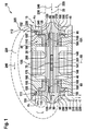
- FIG. 1 shows a semi-longitudinal section through a turbomachine 10th
- FIG. 2 shows a section of the in FIG. 1 shown turbomachine 10.
- the turbomachine 10 is formed in the embodiment as a compressor for a heat pump cycle.
- the turbomachine 10 can also be embodied as a turbocompressor, turbocharger or as a microturbine or as a closed-cycle microturbine. It is also conceivable that the turbomachine 10 is mounted in a (block) cogeneration plant for power and / or heat generation.
- the turbomachine 10 has a rotor 15 and a stator 20.
- the rotor 15 is mounted rotatably about a rotation axis 25 by means of a bearing device 30 on the stator 20.
- the rotor 15 has a first radial impeller 35, a connecting shaft 40 and a second radial impeller 45.
- the first radial impeller 35 includes a first vane assembly 50, a first support assembly 55, and a first shaft portion 60.
- the first support assembly 55 is disposed axially adjacent the first vane assembly 50.
- the first support assembly 95 has a first radially outer end 171. Axially next to the first support assembly 55, on a side facing away from the first blade assembly 50 side, the first shaft portion 60 is arranged.
- the first blade assembly 50, the first support assembly 55 and the first shaft portion 60 are integrally formed of the same material. As a result, a particularly radially and mechanically stable first radial impeller 35 can be provided.
- the first radial impeller 35 has a first receptacle 65.
- the first shaft portion 60 is formed like a hollow shaft.
- the first receptacle 65 extends substantially axially over the entire axial width of the first shaft portion 60.
- the first recording 65 axially wider or narrower than in FIG. 1 is shown formed.
- the connecting shaft 40 has a first connecting shaft portion 70, a second connecting shaft portion 75, and a third connecting shaft portion 80.
- the first connection shaft portion 70 is disposed axially adjacent to the second connection shaft portion 75.
- the third connection shaft portion 80 is disposed axially adjacent to the second connection shaft portion 75 on a side of the second connection shaft portion 75 opposite to the first connection shaft portion 70.
- the first connecting shaft portion 70 is radially outwardly formed corresponding to the first receptacle 65 and engages in the first receptacle 65 and couples the connecting shaft 40 torque-locking with the first radial impeller 35.
- the coupling can be positive and / or cohesive.
- a diameter of the first shaft portion 60 is substantially identical to a diameter of the second connection shaft portion 70.
- the second radial impeller 45 is mirror-symmetrical to a plane of symmetry 85, which is aligned perpendicular to the axis of rotation 25 is formed.
- first radial impeller 35 and the second radial impeller 45 are formed asymmetrically to each other.
- the second radial impeller 45 has a second blade arrangement 90, a second support arrangement 95 and a second shaft section 100.
- the second shaft section 100 and the second support arrangement 95 are arranged on a side of the second radial impeller 45 facing the first support arrangement 55.
- the second support assembly 95 has a second radially outer end 245.
- the second blade arrangement 90 is arranged axially adjacent to the second support arrangement 95 on a side facing away from the first support arrangement 55.
- the second blade assembly 90, the second support assembly 95 and the second shaft portion 100 are integrally formed of the same material.
- the first radial impeller 35 and the second one Radial impeller 45 on the same material.
- the first radial impeller 35 has a different material to the second radial impeller 45.
- the second radial impeller 45 has a second receptacle 101.
- the second receptacle 101 is formed corresponding to the third connection shaft portion 80 of the connection shaft 40.
- the third connection shaft portion 80 engages in the second receptacle 101 and coupled torque-tight, the second radial impeller 45 with the connecting shaft 40.
- the coupling can be made positive and / or cohesive.
- the bearing device 30 is designed as a fluid bearing, in particular as a gas-dynamic fluid bearing, and has a first bearing shell 105 and a second bearing shell 110.
- the bearing shells 105, 110 are formed like a bush.
- the first bearing shell 105 has a first radial section 115 and a first axial section 120.
- the second bearing shell 110 has a second radial section 125 and a second axial section 130.
- the first radial section 115 extends perpendicular to the axis of rotation 25 and adjoins the first axial section 120.
- the first radial section 115 is formed in the shape of a collar in relation to the first axial section 120.
- the bearing shells 105, 110 are mechanically supported by the stator 20.
- the stator 20 has radially on the outside of the bearing shells 105, 110 on an opposite side of the other bearing shell 105 an inner circumferential surface 111, 112 on.
- an inlet gap 151 is provided which has a width a 1 in the radial direction.
- an outlet gap 152 is provided which has a width a 2 in the radial direction.
- the second radial section 125 is arranged perpendicular to the axis of rotation 25 and adjoins the second axial section 130.
- the second radial portion is formed like a collar to the second axial portion 130.
- the first axial section 120 and the second axial section 130 are hollow-cylindrical.
- a drive motor 135 is provided.
- the drive motor 135 is formed in the embodiment as an electric machine.
- the drive motor 135 in this case has windings 140, which are arranged in the stator 20.
- the electric machine 135 has at least one permanent magnet 141.
- the permanent magnet 141 is connected in a torque-locking manner to the second connecting shaft section 75 of the connecting shaft 40.
- the first bearing shell 105 has a first bearing surface 145 on the first radial section 115.
- the first bearing surface 145 is arranged in a first plane of rotation, which is arranged perpendicular to the axis of rotation 25.
- the first bearing surface 145 extends substantially in the radial direction from the first shaft portion 60 to a radially outer end 171 of the first radial impeller 35.
- the first bearing surface 145 is narrower in the radial direction.
- the bearing device 30 on the first support arrangement 55 on a front side facing away from the first blade arrangement 50, has a second bearing surface 150 arranged in a second plane of rotation relative to the rotation axis 25. Between the first bearing surface 145 and the second bearing surface 150, a first gap 155 extending in the radial direction is provided. The first gap 155 is fluidically connected to the inlet gap 151.
- the first bearing shell 105 On an inner circumferential surface of the first axial section 120, the first bearing shell 105 has a third bearing surface 160 extending in the circumferential direction.
- the bearing device 30 comprises a fourth bearing surface 165 on the first shaft section 60 on an outer circumferential surface.
- an axially extending second gap 170 is provided.
- the second gap 170 is fluidly connected to the first gap 155.
- the third bearing surface 160 directly adjoins the first bearing surface 145.
- the third bearing surface 160 is arranged at a distance from the second bearing surface 150.
- the second bearing shell 110 has a fifth bearing surface 175 on the second radial section 125.
- the fifth bearing surface 175 is arranged in a third plane of rotation to the axis of rotation 25.
- the bearing device 30 has a sixth bearing surface 180 on the second support arrangement 95.
- the sixth bearing surface 180 is arranged in a fourth plane of rotation to the axis of rotation 25.
- a third gap 185 extending in the radial direction is provided between the fifth bearing surface 175 and the sixth bearing surface 180.
- the second axial section 130 has a seventh bearing surface 190 on an inner circumferential surface.
- the second shaft portion 100 has an eighth bearing surface 195 on an outer peripheral surface.
- the seventh bearing surface 190 and the eighth bearing surface 195 extend in the circumferential direction.
- a fourth gap 200 is provided between the seventh bearing surface 190 and the eighth bearing surface 195.
- the fourth gap 200 fluidly connects the second gap 170 fluidically with the third gap 185.
- the second and fourth gap 170, 200 are in this case designed as an annular gap, while the first and third gap 155, 185 are formed as a radial gap.
- another gap 201 may be provided, which is formed differently to the gaps 155, 170, 185, 200.
- the turbomachine 10 has a housing 205.
- the housing 205 has an inlet 210, an outlet 215 and in the embodiment by way of example a connection channel 220.
- the inlet 210 can be connected, for example, to a low-pressure side 225 of a heat pump cycle 230.
- the outlet 215 is fluidically connectable to a high pressure side 235 of the heat pump cycle 230.
- the heat pump cycle 230 has in the turbomachine an exemplary gaseous fluid 240 10 as a heat transfer medium.
- the fluid 240 may also be a gas-liquid mixture and / or a gas-solid mixture.
- the second radial impeller 45 is fluidly connected on the upstream side via the inlet 210 with the low pressure side 225. Downstream, the second radial impeller 45 is connected to the connection channel 220.
- the first radial impeller 35 is upstream with the connection channel 220 and downstream connected via the outlet 215 with the high pressure side 235 of the heat pump cycle 230
- the drive motor 135 rotates the rotor 15.
- the second radial impeller 45 sucks the gas 240 via the inlet 210 from the low-pressure side 225 and conveys it radially outward.
- the fluid 240 is compressed to a first pressure level.
- the fluid 240 flows downstream from the second radial impeller 45 into the connection channel 220.
- the fluid 240 is guided via the connection channel 220 from the second radial impeller 45 to the first radial impeller 35.
- the fluid 240 is supplied radially inward of the first blade arrangement 50.
- the first vane assembly 50 radially outwardly compresses the fluid 240 and compresses the fluid 240 from the first pressure level to a second pressure level. Radially outward, the fluid 240 flows from the second radial impeller 45 via the outlet 215 into the high pressure side 235 of the heat pump cycle 230.
- the fluid 240 also serves to support the rotor 15.
- the fluid 240 flows radially outward between the housing 205 and the radially outer end 171 of the first radial impeller 35 in the first gap 155 a.
- the fluid 240 flows radially from outside to inside in the first gap 155. From the first gap 155, the fluid 240 flows into the second gap 170.
- the configuration of the bearing device 30 as a fluid bearing forms the fluid 240 in the first and second gaps 155, 170, respectively Pad, so that the first bearing surface 145 axially spaced from the second bearing surface 150 and the third bearing surface 160 is radially spaced from the fourth bearing surface 165. As a result, a contact contact between the bearing surfaces 145, 150, 160, 165 is avoided.
- the fluid 240 flows along the second gap 170 and along a longitudinal direction of the connecting shaft 40.
- the fluid 240 flows from the second gap 170 into the further gap 201.
- the fluid 240 flows along the drive motor 135 and in particular cools the windings 140
- Drive motor 135 flows the fluid 240 from the further gap 201 into the fourth gap 200.
- the fluid 240 forms another pad, so that the eighth bearing surface 195 is spaced apart from the seventh Storage area 190 rotates. As a result, wear between the second shaft portion 100 and the second bearing shell is avoided.
- the fluid 240 flows into the third gap 185 and flows radially from the inside to the outside.
- the fluid forms a further cushion between the fifth and sixth bearing surfaces 175, 180.
- the fluid 240 exits the third gap 185 via the outlet gap 152 downstream of the second radial impeller 45. Due to the difference in pressure between entry into the first gap 155 and exit from the third gap 185, the fluid 240 flows along the flow path just described across the gaps 155, 170, 185, 200, 201.
- the expansion of the fluid 240 from the second pressure level towards the fluid 240 cools both the bearing device 30 and the drive motor 135.
- the fluid 240 ensures a non-contact running of the radial impellers 35 through the formation of cushioning between the bearing surfaces 145, 150, 160, 165, 175, 180, 190, 195. 45, so that both an axial and a radial abutment of the bearing surfaces 145, 150, 160, 165, 175, 180, 190, 195 are avoided together.
- the above-described embodiment of the turbomachine 10 has the advantage that the rotor 15 can be mounted without contact on both sides of the bearing device 30 designed as a fluid bearing during operation of the turbomachine 10, so that tumbling of the rotor 15 can be avoided. Furthermore, a safe positioning of the rotor 15 is ensured by the fact that the bearing device 30 acts as a plain bearing in this state when starting and at a standstill of the turbomachine 10.
- the bearing shells 105, 110 may further be arranged axially far apart from each other, so that a reliable support of the rotor 15 is ensured.
- the arrangement of the first and second bearing shell 105, 110 in the stator 20, the stator 20 can be formed in one piece and of uniform material. Furthermore, inspection and service reliability for the turbomachine 10 is improved.
- the width a 1 and / or the width a 2 may be less than 50 ⁇ m, in particular less than 10 ⁇ m.
- an efficiency of the turbomachine 10 can be improved.
- the turbomachine 10 is particularly simple.
Abstract
Description
- Die Erfindung betrifft eine Turbomaschine gemäß Patentanspruch 1.
- Aus
DE 10 2011 001 530 A1 ist eine Turbomaschine mit einem ersten und einem zweiten Radiallaufrad bekannt. Die Radiallaufräder sind drehbar gelagert. - Es ist Aufgabe der Erfindung, eine verbesserte Turbomaschine bereitzustellen.
- Diese Aufgabe wird mittels einer Turbomaschine gemäß Patentanspruch 1 gelöst. Vorteilhafte Ausführungsformen sind in den abhängigen Ansprüchen angegeben.
- Erfindungsgemäß wurde erkannt, dass eine verbesserte Turbomaschine dadurch bereitgestellt werden kann, dass die Turbomaschine wenigstens einen Rotor und einen Stator umfasst, wobei der Rotor drehbar um eine Drehachse mittels einer Lagereinrichtung gelagert ist, wobei der Rotor ein erstes Radiallaufrad umfasst, wobei das erste Radiallaufrad eine erste Schaufelanordnung und eine einstückig und materialeinheitlich mit der ersten Schaufelanordnung ausgebildete erste Abstützanordnung umfasst, wobei die Lagereinrichtung eine erste Lagerschale mit einer ersten Lagerfläche umfasst, wobei die Lagereinrichtung an der ersten Abstützanordnung auf einer zur ersten Schaufelanordnung abgewandten Seite eine zweite Lagerfläche umfasst, wobei zwischen der ersten Lagerfläche und der zweiten Lagerfläche ein erster Spalt vorgesehen ist, wobei die erste Lagerfläche und die zweite Lagerfläche über ein im ersten Spalt vorhandenes Fluid zur Lagerung des Rotors miteinander in Wirkverbindung stehen.
Dadurch können die Toleranzen des Radiallaufrads in Verbindung mit der Lagereinrichtung gering gehalten werden, sodass die Turbomaschine einen besonders hohen Wirkungsgrad aufweist. - In einer weiteren Ausführungsform ist die erste Lagerfläche in einer ersten Drehebene zu der Drehachse angeordnet, wobei die zweite Lagerfläche in einer zweiten Drehebene zu der Drehachse angeordnet ist, wobei der erste Spalt axial zwischen der ersten Lagerfläche und der zweiten Lagerfläche angeordnet ist und in radialer Richtung verläuft.
- In einer weiteren Ausführungsform weist das erste Radiallaufrad einen ersten Wellenabschnitt auf. Der erste Wellenabschnitt ist axial neben der ersten Abstützanordnung auf einer der ersten Schaufelanordnung abgewandten Seite angeordnet. Die erste Lagerschale weist eine in Umfangsrichtung verlaufende dritte Lagerfläche auf. Die Lagereinrichtung weist an dem ersten Wellenabschnitt umfangsseitig eine vierte Lagerfläche auf. Radial zwischen der dritten Lagerfläche und der vierten Lagerfläche ist ein in axialer Richtung verlaufender zweiter Spalt vorgesehen, wobei der zweite Spalt vorzugsweise fluidisch mit dem ersten Spalt verbunden ist. Auf diese Weise wird durch die Lagereinrichtung sowohl eine axiale als auch eine radiale Lagerung des ersten Radiallaufrads sichergestellt. Ferner wird durch diese Ausgestaltung eine Bauteilanzahl der Turbomaschine besonders niedrig gehalten, sodass die Turbomaschine besonders kostengünstig hergestellt werden kann.
- In einer weiteren Ausführungsform ist der erste Wellenabschnitt einstückig und materialeinheitlich mit der ersten Abstützanordnung und der ersten Schaufelanordnung ausgebildet. Dadurch können Bauteiltoleranzen besonders niedrig gehalten werden, sodass ein Verluststrom vom Fluid innerhalb der Turbomaschine über den ersten und zweiten Spalt besonders gering ist.
- In einer weiteren Ausführungsform ist die dritte Lagerfläche axial angrenzend an die erste Lagerfläche angeordnet. Dadurch kann das Radiallaufrad besonders kompakt ausgebildet werden.
- In einer weiteren Ausführungsform erstreckt sich die erste Lagerfläche im Wesentlichen in radialer Richtung von dem ersten Wellenabschnitt bis zu einem radial außen liegenden Ende der ersten Abstützanordnung. Dadurch können besonders hohe axiale Kräfte aus dem ersten Radiallaufrad über die Lagereinrichtung abgestützt werden.
- In einer weiteren Ausführungsform umfasst der Rotor ein zweites Radiallaufrad. Das zweite Radiallaufrad ist drehmomentschlüssig mit dem ersten Radiallaufrad gekoppelt. Das zweite Radiallaufrad umfasst eine zweite Schaufelanordnung und eine einstückig und materialeinheitlich mit der zweiten Schaufelanordnung ausgebildete zweite Abstützanordnung. Die zweite Abstützanordnung ist auf einer der ersten Abstützanordnung zugewandten Seite des zweiten Radiallaufrads angeordnet. Die Lagereinrichtung umfasst eine zweite Lagerschale mit einer in einer dritten Drehebene zu der Drehachse angeordneten fünften Lagerfläche. Die Lagereinrichtung umfasst eine an der zweiten Abstützanordnung, auf einer zur ersten Abstützanordnung zugewandten Seite, in einer vierten Drehebene zu der Drehachse angeordnete sechste Lagerfläche. Zwischen der fünften Lagerfläche und der sechsten Lagerfläche ist ein in radialer Richtung verlaufender dritter Spalt vorgesehen. Dadurch kann eine axiale Position der beiden Radiallaufräder über die beiden Radiallaufräder selbst festgelegt werden.
- In einer weiteren Ausführungsform ist der dritte Spalt fluidisch mit dem zweiten Spalt verbunden.
- In einer weiteren Ausführungsform weist die Turbomaschine einen Verbindungskanal auf. Das zweite Radiallaufrad ist stromaufwärtsseitig mit einer Niederdruckseite und stromabwärtsseitig mit dem Verbindungskanal verbunden. Stromaufwärtsseitig ist das erste Radiallaufrad mit dem Verbindungskanal und stromabwärtsseitig mit einer Hochdruckseite fluidisch verbunden. Das zweite Radiallaufrad ist ausgebildet, das Fluid von der Niederdruckseite in den Verbindungskanal zu fördern und einen Druck des Fluids auf ein erstes Druckniveau anzuheben. Das erste Radiallaufrad ist ausgebildet, das Fluid von dem Verbindungskanal zu der Hochdruckseite zu fördern und das Fluid auf ein zweites Druckniveau anzuheben. Die Spalten sind ausgebildet, den Teil des Fluids von der Hochdruckseite hin zu dem ersten Druckniveau entlang der Lagerflächen zu führen. Dadurch wird eine Kühlung der Lagerflächen erzielt.
- In einer weiteren Ausführungsform weist das zweite Radiallaufrad einen zweiten Wellenabschnitt auf. Der zweite Wellenabschnitt ist axial neben der zweiten Abstützanordnung auf einer dem ersten Radiallaufrad zugewandten Seite angeordnet. Der zweite Wellenabschnitt ist einstückig und materialeinheitlich mit der zweiten Abstützanordnung und der zweiten Schaufelanordnung ausgebildet. Der Rotor weist eine Verbindungswelle auf. Die Verbindungswelle ist axial zumindest teilweise zwischen dem ersten Wellenabschnitt und dem zweiten Wellenabschnitt angeordnet und verbindet drehmomentschlüssig den ersten Wellenabschnitt mit dem zweiten Wellenabschnitt.
- In einer weiteren Ausführungsform weist der erste Wellenabschnitt und/oder der zweite Wellenabschnitt eine Aufnahme und die Verbindungswelle an wenigstens einem Längsende einen Verbindungswellenabschnitt auf. Der Verbindungswellenabschnitt greift in die Aufnahme ein und koppelt den ersten und/oder den zweiten Wellenabschnitt mit der Verbindungswelle. Vorzugsweise ist die Aufnahme axial auf Höhe der vierten Lagerfläche angeordnet.
- In einer weiteren Ausführungsform weist die erste Lagerschale und das erste Radiallaufrad einen identischen Werkstoff auf. Zusätzlich oder alternativ weist die erste Lagerschale und/oder das erste Radiallaufrad einen der folgenden Werkstoffe auf: Hartmetall, Keramik.
- In einer weiteren Ausführungsform ist die Lagereinrichtung als Fluidlager, insbesondere als dynamisches Fluidlager, ausgebildet ist.
- Nachfolgend wird die Erfindung anhand von Figuren näher erläutert. Dabei zeigen:
-
Figur 1 einen Halblängsschnitt durch eine Turbomaschine; und -
Figur 2 einen Ausschnitt des inFigur 1 gezeigten Halblängsschnitts durch die Turbomaschine. -
Figur 1 zeigt einen Halblängsschnitt durch eine Turbomaschine 10.Figur 2 zeigt einen Ausschnitt der inFigur 1 gezeigten Turbomaschine 10. Die Turbomaschine 10 ist in der Ausführungsform als Verdichter für einen Wärmepumpenkreislauf ausgebildet. Die Turbomaschine 10 ist aber auch als Turbokompressor, Turbolader oder als Mikrogasturbine oder als Closed-Cycle-Mikrogasturbine ausbildbar. Auch ist denkbar, dass die Turbomaschine 10 in einem (Block-) Heizkraftwerk zur Strom- und/oder Wärmeerzeugung montiert ist. - Die Turbomaschine 10 weist einen Rotor 15 und einen Stator 20 auf. Der Rotor 15 ist drehbar um eine Drehachse 25 mittels einer Lagereinrichtung 30 an dem Stator 20 gelagert.
- Der Rotor 15 weist ein erstes Radiallaufrad 35, eine Verbindungswelle 40 und ein zweites Radiallaufrad 45 auf.
- Das erste Radiallaufrad 35 umfasst eine erste Schaufelanordnung 50, eine erste Abstützanordnung 55 und einen ersten Wellenabschnitt 60. Die erste Abstützanordnung 55 ist axial angrenzend an die erste Schaufelanordnung 50 angeordnet. Die erste Abstützanordnung 95 weist ein erstes radial äußeres Ende 171 auf. Axial neben der ersten Abstützanordnung 55, auf einer zur ersten Schaufelanordnung 50 abgewandten Seite, ist der erste Wellenabschnitt 60 angeordnet. Die erste Schaufelanordnung 50, die erste Abstützanordnung 55 und der erste Wellenabschnitt 60 sind einstückig und materialeinheitlich ausgebildet. Dadurch kann ein insbesondere mechanisch und thermisch stabiles erstes Radiallaufrad 35 bereitgestellt werden.
- Im ersten Wellenabschnitt 60 weist das erste Radiallaufrad 35 eine erste Aufnahme 65 auf. Im Bereich der ersten Aufnahme 65 ist der erste Wellenabschnitt 60 hohlwellenartig ausgebildet. In der Ausführungsform erstreckt sich die erste Aufnahme 65 im Wesentlichen axial über die gesamte axiale Breite des ersten Wellenabschnitts 60. Selbstverständlich ist auch denkbar, dass die erste Aufnahme 65 axial breiter oder schmaler als in
Figur 1 gezeigt ausgebildet ist. - Die Verbindungswelle 40 weist einen ersten Verbindungswellenabschnitt 70, einen zweiten Verbindungswellenabschnitt 75 und einen dritten Verbindungswellenabschnitt 80 auf. Der erste Verbindungswellenabschnitt 70 ist axial angrenzend an den zweiten Verbindungswellenabschnitt 75 angeordnet. Der dritte Verbindungswellenabschnitt 80 ist axial angrenzend an den zweiten Verbindungswellenabschnitt 75 auf einer zum ersten Verbindungswellenabschnitt 70 gegenüberliegenden Seite des zweiten Verbindungswellenabschnitts 75 angeordnet. Der erste Verbindungswellenabschnitt 70 ist radial außenseitig korrespondierend zu der ersten Aufnahme 65 ausgebildet und greift in die erste Aufnahme 65 und koppelt die Verbindungswelle 40 drehmomentschlüssig mit dem ersten Radiallaufrad 35. Die Kopplung kann form- und/oder stoffschlüssig erfolgen. In der Ausführungsform ist ein Durchmesser des ersten Wellenabschnitts 60 im Wesentlichen identisch zu einem Durchmesser des zweiten Verbindungswellenabschnitts 70.
- Das zweite Radiallaufrad 45 ist spiegelsymmetrisch zu einer Symmetrieebene 85, die senkrecht zu Drehachse 25 ausgerichtet ist, ausgebildet. Selbstverständlich ist auch denkbar, dass das erste Radiallaufrad 35 und das zweite Radiallaufrad 45 asymmetrisch zueinander ausgebildet sind.
- Das zweite Radiallaufrad 45 weist eine zweite Schaufelanordnung 90, eine zweite Abstützanordnung 95 und einen zweiten Wellenabschnitt 100 auf. Der zweite Wellenabschnitt 100 und die zweite Abstützanordnung 95 sind auf einer zur ersten Abstützanordnung 55 zugewandten Seite des zweiten Radiallaufrads 45 angeordnet. Die zweite Abstützanordnung 95 weist ein zweites radial äußeres Ende 245 auf. Die zweite Schaufelanordnung 90 ist axial angrenzend zu der zweiten Abstützanordnung 95 auf einer zur ersten Abstützanordnung 55 abgewandten Seite angeordnet. Die zweite Schaufelanordnung 90, die zweite Abstützanordnung 95 und der zweite Wellenabschnitt 100 sind einstückig und materialeinheitlich ausgebildet. Dadurch kann ein insbesondere mechanisch und thermisch stabiles zweites Radiallaufrad 45 bereitgestellt werden. Dabei weisen in der Ausführungsform beispielhaft das erste Radiallaufrad 35 und das zweite Radiallaufrad 45 den gleichen Werkstoff auf. Selbstverständlich ist auch denkbar, dass das erste Radiallaufrad 35 einen unterschiedlichen Werkstoff zu dem zweiten Radiallaufrad 45 aufweist. In dem zweiten Wellenabschnitt 100 weist das zweite Radiallaufrad 45 eine zweite Aufnahme 101 auf. Die zweite Aufnahme 101 ist korrespondierend zu dem dritten Verbindungswellenabschnitt 80 der Verbindungswelle 40 ausgebildet. Dabei greift der dritte Verbindungswellenabschnitt 80 in die zweite Aufnahme 101 ein und koppelt drehmomentschlüssig das zweite Radiallaufrad 45 mit der Verbindungswelle 40. Die Kopplung kann form- und/oder stoffschlüssig erfolgen.
- Die Lagereinrichtung 30 ist als Fluidlager, insbesondere als gasdynamisches Fluidlager, ausgebildet und weist eine erste Lagerschale 105 und eine zweite Lagerschale 110 auf. Die Lagerschalen 105, 110 sind buchsenartig ausgebildet. Dabei weist die erste Lagerschale 105 einen ersten Radialabschnitt 115 und einen ersten Axialabschnitt 120 auf. Die zweite Lagerschale 110 weist einen zweiten Radialabschnitt 125 und einen zweiten Axialabschnitt 130 auf. Der erste Radialabschnitt 115 erstreckt sich senkrecht zu der Drehachse 25 und grenzt an den ersten Axialabschnitt 120 an. Dabei ist der erste Radialabschnitt 115 kragenförmig gegenüber dem ersten Axialabschnitt 120 ausgebildet.
- Dabei werden die Lagerschalen 105, 110 durch den Stator 20 mechanisch getragen. Der Stator 20 weist radial außenseitig der Lagerschalen 105, 110 auf einer jeweils der anderen Lagerschale 105 abgewandten Seite eine innere Umfangsfläche 111, 112 auf. Zwischen einer ersten inneren Umfangsfläche 111 und dem ersten radial äußeren Ende 171 ist ein Einlaufspalt 151 vorgesehen, der in radialer Richtung eine Breite a1 aufweist, vorgesehen. Zwischen einer zweiten inneren Umfangsfläche 112 und dem zweiten radial äußeren Ende 245 ist ein Austrittsspalt 152 vorgesehen, der in radialer Richtung eine Breite a2 aufweist, vorgesehen.
- Der zweite Radialabschnitt 125 ist senkrecht der Drehachse 25 angeordnet und grenzt an den zweiten Axialabschnitt 130 an. Dabei ist der zweite Radialabschnitt kragenförmig zu dem zweiten Axialabschnitt 130 ausgebildet. Der erste Axialabschnitt 120 und der zweite Axialabschnitt 130 sind hohlzylindrisch ausgebildet. Axial zwischen der ersten Lagerschale 105 und der zweiten Lagerschale 110 ist ein Antriebsmotor 135 vorgesehen. Selbstverständlich ist auch denkbar, dass auf den Antriebsmotor 135 verzichtet wird. Der Antriebsmotor 135 ist in der Ausführungsform als elektrische Maschine ausgebildet. Der Antriebsmotor 135 weist dabei Wicklungen 140 auf, die in dem Stator 20 angeordnet sind. Die elektrische Maschine 135 weist wenigstens einen Permanentmagneten 141 auf. Der Permanentmagnet 141 ist dabei drehmomentschlüssig mit dem zweiten Verbindungswellenabschnitt 75 der Verbindungswelle 40 verbunden.
- Die erste Lagerschale 105 weist am ersten Radialabschnitt 115 eine erste Lagerfläche 145 auf. Die erste Lagerfläche 145 ist dabei in einer ersten Drehebene, die senkrecht zur Drehachse 25 angeordnet ist, angeordnet. In der Ausführungsform erstreckt sich die erste Lagerfläche 145 im Wesentlichen in radialer Richtung von dem ersten Wellenabschnitt 60 bis zu einem radial außen liegenden Ende 171 des ersten Radiallaufrads 35. Selbstverständlich ist auch denkbar, dass die erste Lagerfläche 145 in radialer Richtung schmaler ausgebildet ist.
- Ferner weist die Lagereinrichtung 30 an der ersten Abstützanordnung 55, auf einer zur ersten Schaufelanordnung 50 abgewandten Stirnseite, eine in einer zweiten Drehebene zu der Drehachse 25 angeordnete zweite Lagerfläche 150 auf. Zwischen der ersten Lagerfläche 145 und der zweiten Lagerfläche 150 ist ein in radialer Richtung verlaufender erster Spalt 155 vorgesehen. Der erste Spalt 155 ist fluidisch mit dem Einlaufspalt 151 verbunden.
An einer inneren Umfangsfläche des ersten Axialabschnitts 120 weist die erste Lagerschale 105 eine in Umfangsrichtung verlaufende dritte Lagerfläche 160 auf. Ferner umfasst die Lagereinrichtung 30 an dem ersten Wellenabschnitt 60 an einer äußeren Umfangsfläche eine vierte Lagerfläche 165. Radial zwischen der dritten Lagerfläche 160 und der vierten Lagerfläche 165 ist ein in axialer Richtung verlaufender zweiter Spalt 170 vorgesehen. Der zweite Spalt 170 ist dabei fluidisch mit dem ersten Spalt 155 verbunden. In der Ausführungsform grenzt die dritte Lagerfläche 160 direkt an die erste Lagerfläche 145 an. Selbstverständlich ist auch denkbar, dass die dritte Lagerfläche 160 beabstandet zu der zweiten Lagerfläche 150 angeordnet ist. - Die zweite Lagerschale 110 weist am zweiten Radialabschnitt 125 eine fünfte Lagerfläche 175 auf. Die fünfte Lagerfläche 175 ist dabei in einer dritten Drehebene zu der Drehachse 25 angeordnet. Ferner weist die Lagereinrichtung 30 an der zweiten Abstützanordnung 95 eine sechste Lagerfläche 180 auf. Die sechste Lagerfläche 180 ist in einer vierten Drehebene zu der Drehachse 25 angeordnet. Dabei ist zwischen der fünften Lagerfläche 175 und der sechsten Lagerfläche 180 ein in radialer Richtung verlaufender dritter Spalt 185 vorgesehen.
- Der zweite Axialabschnitt 130 weist an einer inneren Umfangsfläche eine siebte Lagerfläche 190 auf. Der zweite Wellenabschnitt 100 weist an einer äußeren Umfangsfläche eine achte Lagerfläche 195 auf. Die siebte Lagerfläche 190 und die achte Lagerfläche 195 verlaufen in Umfangsrichtung. Dabei ist zwischen der siebten Lagerfläche 190 und der achten Lagerfläche 195 ein vierter Spalt 200 vorgesehen. Der vierte Spalt 200 verbindet fluidisch den zweiten Spalt 170 fluidisch mit dem dritten Spalt 185. Der zweite und vierte Spalt 170, 200 sind hierbei als Ringspalt ausgebildet, während hingegen der erste und dritte Spalt 155, 185 als Radialspalt ausgebildet sind. Ferner kann axial zwischen dem zweiten und vierten Spalt 170, 200 wenigstens beispielhaft ein weiterer Spalt 201 vorgesehen sein, der unterschiedlichen zu den Spalten 155, 170, 185, 200 ausgebildet ist.
- Die Turbomaschine 10 weist ein Gehäuse 205 auf. Das Gehäuse 205 weist einen Einlass 210, einen Auslass 215 und in der Ausführungsform beispielhaft einen Verbindungskanal 220 auf. Der Einlass 210 ist dabei beispielsweise mit einer Niederdruckseite 225 eines Wärmepumpenkreislaufs 230 verbindbar. Der Auslass 215 ist fluidisch mit einer Hochdruckseite 235 des Wärmepumpenkreislaufs 230 verbindbar. Der Wärmepumpenkreislauf 230 weist in der Turbomaschine ein beispielhaft gasförmiges Fluid 240 10 als Wärmeträgermedium auf. Es wird darauf hingewiesen, dass das Fluid 240 auch ein Gas- Flüssigkeits-Gemisch und/oder ein Gas-Festkörpergemisch sein kann. Das zweite Radiallaufrad 45 ist stromaufwärtsseitig über den Einlass 210 mit der Niederdruckseite 225 fluidisch verbunden. Stromabwärtsseitig ist das zweite Radiallaufrad 45 mit dem Verbindungskanal 220 verbunden. Das erste Radiallaufrad 35 ist stromaufwärtsseitig mit dem Verbindungskanal 220 und stromabwärtsseitig über den Auslass 215 mit der Hochdruckseite 235 des Wärmepumpenkreislaufs 230 verbunden.
- Wird dem Antriebsmotor 135 (elektrische) Energie zugeführt, so versetzt der Antriebsmotor 135 den Rotor 15 in Rotation. Dadurch saugt das zweite Radiallaufrad 45 über den Einlass 210 aus der Niederdruckseite 225 das Gas 240 an und fördert es radial nach außen hin. Dabei wird das Fluid 240 auf ein erstes Druckniveau verdichtet. Mit dem ersten Druckniveau strömt das Fluid 240 stromabwärtsseitig von dem zweiten Radiallaufrad 45 in den Verbindungskanal 220. Das Fluid 240 wird über den Verbindungskanal 220 von dem zweiten Radiallaufrad 45 zum ersten Radiallaufrad 35 geführt. Dabei wird das Fluid 240 radial innen der ersten Schaufelanordnung 50 zugeführt. Die erste Schaufelanordnung 50 verdichtet radial nach außen hin das Fluid 240 und verdichtet das Fluid 240 vom ersten Druckniveau auf ein zweites Druckniveau. Radial außen strömt das Fluid 240 von dem zweiten Radiallaufrad 45 über den Auslass 215 in die Hochdruckseite 235 des Wärmepumpenkreislaufs 230.
- Das Fluid 240 dient auch zur Lagerung des Rotors 15. Das Fluid 240 strömt radial außenseitig zwischen dem Gehäuse 205 und dem radial äußeren Ende 171 des ersten Radiallaufrads 35 in den ersten Spalt 155 ein. Das Fluid 240 strömt radial von außen nach innen im ersten Spalt 155. Vom ersten Spalt 155 strömt das Fluid 240 in den zweiten Spalt 170. Durch die Ausgestaltung der Lagereinrichtung 30 als Fluidlager bildet das Fluid 240 im ersten und zweiten Spalt 155, 170 jeweils ein Polster aus, so dass die erste Lagerfläche 145 axial beabstandet zu der zweiten Lagerfläche 150 und die dritte Lagerfläche 160 radial beabstandet zu der vierten Lagerfläche 165 ist. Dadurch wird ein Berührkontakt zwischen den Lagerflächen 145, 150, 160, 165 vermieden.
- Das Fluid 240 strömt entlang des zweiten Spalts 170 und entlang einer Längsrichtung der Verbindungswelle 40. Das Fluid 240 strömt vom zweiten Spalt 170 in den weiteren Spalt 201. Das Fluid 240 strömt entlang des Antriebsmotors 135 und kühlt hierbei insbesondere die Wicklungen 140. Nach Passieren des Antriebsmotors 135 strömt das Fluid 240 vom weiteren Spalt 201 in den vierten Spalt 200 ein. Dabei bildet im vierten Spalt 200 das Fluid 240 ein weiteres Polster aus, so dass die achte Lagerfläche 195 beabstandet zu der siebten Lagerfläche 190 rotiert. Dadurch wird ein Verschleiß zwischen dem zweiten Wellenabschnitt 100 und der zweiten Lagerschale vermieden.
- Vom vierten Spalt 200 strömt das Fluid 240 in den dritten Spalt 185 und strömt radial von innen nach außen hin. Im dritten Spalt 185 bildet das Fluid ein weiteres Polster zwischen der fünften und sechsten Lagerfläche 175, 180 aus. An dem radial äußeren zweiten Ende 245 des zweiten Radiallaufrads 45 tritt das Fluid 240 über den Austrittsspalt 152 stromabwärtsseitig des zweiten Radiallaufrads 45 aus dem dritten Spalt 185 aus. Durch den Druckunterschied zwischen Eintritt in den ersten Spalt 155 und Austritt aus dem dritten Spalt 185 strömt das Fluid 240 entlang des eben beschrieben Strömungsweges über die Spalte 155, 170, 185, 200, 201. Durch die Expansion des Fluids 240 vom zweiten Druckniveau hin zum ersten Druckniveau kühlt das Fluid 240 sowohl die Lagereinrichtung 30 als auch den Antriebsmotor 135. Ferner sorgt das Fluid 240 durch die Polsterbildung zwischen den Lagerflächen 145, 150, 160, 165, 175, 180, 190, 195 für einen berührungslosen Lauf der Radiallaufräder 35, 45, sodass sowohl ein axiales als auch ein radiales Anschlagen der Lagerflächen 145, 150, 160, 165, 175, 180, 190, 195 aneinander vermieden wird.
- Besonders gute Anlaufeigenschaften, also wenn beispielsweise die Lagerflächen 145, 150, 160, 165, 175, 180, 190, 195 einen Berührkontakt aneinander aufweisen und/oder, wenn das Fluid 240 noch nicht hinreichend starke Polsterbildung aufweist, werden erzielt, wenn das Radiallaufrad 35, 45 und die Lagerschale 105, 110 einen identischen Werkstoff aufweisen. Dabei ist von besonderem Vorteil, wenn die Lagerschale 105, 110 und das Radiallaufrad 35, 45 Hartmetall und/oder Keramik aufweist.
- Ferner wird durch die oben beschriebene Anordnung der Spalte 155, 170, 185, 200 sichergestellt, dass, insbesondere eine durch den Druckunterschied des Fluides 240 am ersten Radiallaufrad 35 zum zweiten Radiallaufrad 45 eine vom ersten Radiallaufrad 35 in Richtung der Drehachse 25 zum zweiten Radiallaufrad 45 wirkende Axialkraft F über den ersten Spalt 155 an der ersten Lagerschale 105 abgestützt werden kann. Dadurch wird ein Anschlagen des ersten Radiallaufrads 35 an der ersten Lagerschale 105 vermieden.
- Die oben beschriebene Ausgestaltung der Turbomaschine 10 hat den Vorteil, dass der Rotor 15 beidseitig der als Fluidlager ausgebildeten Lagereinrichtung 30 im Betrieb der Turbomaschine 10 berührungslos gelagert werden kann, so dass ein Taumeln des Rotors 15 vermieden werden kann. Ferner wird beim Anfahren und im Stillstand der Turbomaschine 10 eine sichere Positionierung des Rotors 15 dadurch gewährleistet, dass die Lagereinrichtung 30 in diesem Zustand als Gleitlager fungiert. Insbesondere können die Lagerschalen 105, 110 ferner axial weit voneinander beabstandet angeordnet werden, so dass eine zuverlässige Abstützung des Rotors 15 gewährleistet ist. Ferner ermöglicht die Anordnung der ersten und zweiten Lagerschale 105, 110 im Stator 20, dass der Stator 20 einstückig und materialeinheitlich ausgebildet werden kann. Ferner wird eine Inspektions- und Servicezuverlässigkeit für die Turbomaschine 10 verbessert.
- Durch die oben beschriebene Ausgestaltung können der Eintrittsspalt 151 und der Austrittsspalt 152 zwischen dem Stator 20 und dem Radiallaufrad 35, 45, aber auch ein Freiraum 250 zwischen der Schaufelanordnung 50, 90 und dem Gehäuse 205 besonders gering gehalten werden. Dabei können die Breite a1 und/oder die Breite a2 kleiner 50 µm, insbesondere kleiner 10 µm, gewählt werden. Dadurch kann ein Wirkungsgrad der Turbomaschine 10 verbessert werden. Insbesondere kann durch die geringe Breite a1, a2 eine Verbesserung der Zuverlässigkeit der Turbomaschine 10 erzielt werden.
- Ferner werden durch die einstückige und materialeinheitliche Ausgestaltung des Radiallaufrads 35, 40 werden innerhalb des Radiallaufrads 35, 45 Toleranzketten vermieden. Dadurch kann eine Bauteiltoleranz des Rotors 15 in einer Größenordnung einer Lagertoleranz der Lagereinrichtung 30 gewählt werden. Insbesondere kann die Breite a1, a2 in radialer Richtung korrespondierend zur Lagertoleranz gewählt werden, sodass die Breite a1, a2 eine gleiche Größenordnung wie die Lagertoleranz der Lagereinrichtung 30 aufweist. Ferner ist ein Transfer von üblicherweise bei der Montage der Radiallaufräder 35, 45 sich aufsummierenden Toleranzketten auf die Breite a1, a2 und den Freiraum 250 nicht notwendig. Ferner ist die Turbomaschine 10 besonders einfach ausgebildet.
- Obwohl die Erfindung im Detail durch das bevorzugte Ausführungsbeispiel näher illustriert und beschrieben wurde, so ist die Erfindung nicht durch die offenbarten Beispiele eingeschränkt und andere Variationen können vom Fachmann hieraus abgeleitet werden, ohne den Schutzumfang der Erfindung zu verlassen.
Claims (13)
- Turbomaschine (10) mit wenigstens einem Rotor (15) und einem Stator (20),- wobei der Rotor (15) drehbar um eine Drehachse (25) mittels einer Lagereinrichtung (30) gelagert ist,- wobei der Rotor (15) ein erstes Radiallaufrad (35) umfasst- wobei das erste Radiallaufrad (35) eine erste Schaufelanordnung (50) und eine einstückig und materialeinheitlich mit der ersten Schaufelanordnung (50) ausgebildete erste Abstützanordnung (55) umfasst,- wobei die Lagereinrichtung (30) eine erste Lagerschale (105) mit einer ersten Lagerfläche (145) umfasst,- wobei die Lagereinrichtung (30) an der ersten Abstützanordnung (55) auf einer zur ersten Schaufelanordnung (50) abgewandten Seite eine zweite Lagerfläche (150) umfasst,- wobei zwischen der ersten Lagerfläche (145) und der zweiten Lagerfläche (150) ein erster Spalt (155) vorgesehen ist,- wobei die erste Lagerfläche (145) und die zweite Lagerfläche (150) über ein im ersten Spalt (155) vorhandenes Fluid (240) zur Lagerung des Rotors (15) miteinander in Wirkverbindung stehen.
- Turbomaschine (10) nach Anspruch 1,- wobei die erste Lagerfläche (145) in einer ersten Drehebene zu der Drehachse (25) angeordnet ist,- wobei die zweite Lagerfläche (150) in einer zweiten Drehebene zu der Drehachse (25) angeordnet ist,- wobei der erste Spalt (155) axial zwischen der ersten Lagerfläche (145) und der zweiten Lagerfläche (150) angeordnet ist und in radialer Richtung verläuft.
- Turbomaschine (10) nach Anspruch 1 oder 2,- wobei das erste Radiallaufrad (35) einen ersten Wellenabschnitt (60) aufweist,- wobei der erste Wellenabschnitt (60) axial neben der ersten Abstützanordnung (55) auf einer der ersten Schaufelanordnung (50) abgewandten Seite angeordnet ist,- wobei die erste Lagerschale (105) eine in Umfangsrichtung verlaufende dritte Lagerfläche (160) umfasst,- wobei die Lagereinrichtung (30) an dem ersten Wellenabschnitt (60) umfangsseitig eine vierte Lagerfläche (165) umfasst,- wobei radial zwischen der dritten Lagerfläche (160) und der vierten Lagerfläche (165) ein in axialer Richtung verlaufender zweiter Spalt (170) vorgesehen ist,- wobei der zweite Spalt (170) vorzugsweise fluidisch mit dem ersten Spalt (155) verbunden ist.
- Turbomaschine (10) nach Anspruch 3, wobei der erste Wellenabschnitt (60) einstückig und materialeinheitlich mit der ersten Abstützanordnung (55) und der ersten Schaufelanordnung (50) ausgebildet ist.
- Turbomaschine (10) nach Anspruch 3 oder 4, wobei die dritte Lagerfläche (160) angrenzend an die erste Lagerfläche (145) angeordnet ist.
- Turbomaschine (10) nach einem der Ansprüche 3 bis 5, wobei die erste Lagerfläche (145) sich im Wesentlichen in radialer Richtung von dem ersten Wellenabschnitt (60) bis zu einem radial außen liegenden Ende (171) der ersten Abstützanordnung (55) erstreckt.
- Turbomaschine (10) nach einem der Ansprüche 1 bis 6,- wobei der Rotor (15) ein zweites Radiallaufrad (45) umfasst,- wobei das zweite Radiallaufrad (45) drehmomentschlüssig mit dem ersten Radiallaufrad (35) gekoppelt ist,- wobei das zweite Radiallaufrad (45) eine zweite Schaufelanordnung (90) und eine einstückig und materialeinheitlich mit der zweiten Schaufelanordnung (90) ausgebildete zweite Abstützanordnung (95) umfasst,- wobei die zweite Abstützanordnung (95) auf einer der ersten Abstützanordnung (55) zugewandten Seite des zweiten Radiallaufrads (45) angeordnet ist,- wobei die Lagereinrichtung (30) eine zweite Lagerschale (110) mit einer in einer dritten Drehebene zu der Drehachse (25) angeordneten fünften Lagerfläche (175) umfasst,- wobei die Lagereinrichtung (30) eine an der zweiten Abstützanordnung (95) auf einer zur ersten Abstützanordnung (55) zugewandten Seite in einer vierten Drehebene zu der Drehachse (25) angeordnete sechste Lagerfläche (180) umfasst,- wobei zwischen der fünften Lagerfläche (175) und der sechsten Lagerfläche (180) ein in radialer Richtung verlaufender dritter Spalt (185) vorgesehen ist.
- Turbomaschine (10) nach Anspruch 7, wobei der dritte Spalt (185) mit dem zweiten Spalt (170) fluidisch verbunden ist.
- Turbomaschine (10) nach Anspruch 7 oder 8,- aufweisend einen Verbindungskanal (220),- wobei das zweite Radiallaufrad (45) stromaufwärtsseitig mit einer Niederdruckseite (225) und stromabwärtsseitig mit dem Verbindungskanal (220) verbunden ist,- wobei stromaufwärtsseitig das erste Radiallaufrad (35) mit dem Verbindungskanal (220) verbunden und stromabwärtsseitig mit einer Hochdruckseite (235) fluidisch verbunden ist,- wobei das zweite Radiallaufrad (45) ausgebildet ist, das Fluid (240) von der Niederdruckseite (225) in den Verbindungskanal (220) zu fördern und einen Druck des Fluids (240) auf ein erstes Druckniveau anzuheben,- wobei das erste Radiallaufrad (35) ausgebildet ist, das Fluid (240) von dem Verbindungskanal (220) zu der Hochdruckseite (235) zu fördern und das Fluid auf ein zweites Druckniveau anzuheben,- wobei die Spalten (155, 170, 185, 200) ausgebildet sind, den Teil des Fluids (240) von der Hochdruckseite (235) hin zu dem ersten Druckniveau entlang der Lagerflächen (145, 150, 160, 165, 175, 180, 190, 195) zu führen.
- Turbomaschine (10) nach einem der Ansprüche 7 bis 9,- wobei das zweite Radiallaufrad (45) einen zweiten Wellenabschnitt (100) aufweist,- wobei der zweite Wellenabschnitt (100) axial neben der zweiten Abstützanordnung (95) auf einer dem erstem Radiallaufrad (35) zugewandten Seite angeordnet ist,- der zweite Wellenabschnitt (100) einstückig und materialeinheitlich mit der zweiten Abstützanordnung (95) und der zweiten Schaufelanordnung (90) ausgebildet ist,- wobei der Rotor (15) eine Verbindungswelle (40) umfasst,- wobei die Verbindungswelle (40) axial zumindest teilweise zwischen dem ersten Wellenabschnitt (60) und dem zweiten Wellenabschnitt (100) angeordnet ist und drehmomentschlüssig den ersten Wellenabschnitt (60) mit dem zweiten Wellenabschnitt (100) verbindet.
- Turbomaschine (10) nach Anspruch 10,- wobei der erste Wellenabschnitt (60) und/oder der zweite Wellenabschnitt (100) eine Aufnahme (65) und die Verbindungswelle (40) an wenigstens einem Längsende einen Verbindungswellenabschnitt (70, 80) aufweist,- wobei der Verbindungswellenabschnitt (70, 80) in die Aufnahme (65, 101) eingreift und den ersten und/oder zweiten Wellenabschnitt (60, 100) mit der Verbindungswelle (40) koppelt,- wobei vorzugsweise die Aufnahme (65, 101) zumindest teilweise axial auf Höhe der vierten Lagerfläche (165) angeordnet ist.
- Turbomaschine (10) nach Anspruch 11,- wobei die erste Lagerschale (105) und das erste Radiallaufrad (35) einen identischen Werkstoff aufweisen,- und/oder- wobei die erste Lagerschale (105) und/oder das erste Radiallaufrad (35) einen der folgenden Werkstoffe aufweisen: Hartmetall, Keramik.
- Turbomaschine (10) nach einem der Ansprüche 1 bis 12, wobei die Lagereinrichtung (30) als Fluidlager, insbesondere als dynamisches Fluidlager, ausgebildet ist.
Applications Claiming Priority (1)
| Application Number | Priority Date | Filing Date | Title |
|---|---|---|---|
| DE102015209682.3A DE102015209682A1 (de) | 2015-05-27 | 2015-05-27 | Turbomaschine |
Publications (2)
| Publication Number | Publication Date |
|---|---|
| EP3098452A1 true EP3098452A1 (de) | 2016-11-30 |
| EP3098452B1 EP3098452B1 (de) | 2019-10-16 |
Family
ID=55650127
Family Applications (1)
| Application Number | Title | Priority Date | Filing Date |
|---|---|---|---|
| EP16160651.2A Active EP3098452B1 (de) | 2015-05-27 | 2016-03-16 | Turbomaschine |
Country Status (2)
| Country | Link |
|---|---|
| EP (1) | EP3098452B1 (de) |
| DE (1) | DE102015209682A1 (de) |
Cited By (2)
| Publication number | Priority date | Publication date | Assignee | Title |
|---|---|---|---|---|
| US20190170190A1 (en) * | 2016-08-12 | 2019-06-06 | Industry-University Cooperation Foundation Hanyang University Erica Campus | Air bearing and rotor system |
| WO2021164932A1 (de) * | 2020-02-19 | 2021-08-26 | Robert Bosch Gmbh | Gaszuführvorrichtung |
Citations (6)
| Publication number | Priority date | Publication date | Assignee | Title |
|---|---|---|---|---|
| US3612628A (en) * | 1968-01-22 | 1971-10-12 | Lucas Industries Ltd | Gas bearings |
| GB2108595A (en) * | 1981-11-03 | 1983-05-18 | Mtu Muenchen Gmbh | Gas bearings |
| US6231302B1 (en) * | 1999-06-08 | 2001-05-15 | G. Fonda Bonardi | Thermal control system for gas-bearing turbocompressors |
| EP1205678A1 (de) * | 2000-11-07 | 2002-05-15 | Ingersoll-Rand Company | Gaslager |
| US20080273990A1 (en) * | 2007-05-03 | 2008-11-06 | Tark, Inc. | Two-stage hydrodynamic pump and method |
| DE102011001530A1 (de) | 2011-03-24 | 2012-09-27 | Atlas Copco Energas Gmbh | Turbomaschine |
Family Cites Families (4)
| Publication number | Priority date | Publication date | Assignee | Title |
|---|---|---|---|---|
| DE69114139T2 (de) * | 1991-12-19 | 1996-04-04 | United Technologies Corp | Kühlung für Lager einer Luftkreisanlage. |
| US7948105B2 (en) * | 2007-02-01 | 2011-05-24 | R&D Dynamics Corporation | Turboalternator with hydrodynamic bearings |
| DE102008014684A1 (de) * | 2008-03-18 | 2009-10-15 | Continental Automotive Gmbh | Turbolader mit einer Lageranordnung zur Lagerung einer Welle des Turboladers |
| DE102008059598A1 (de) * | 2008-11-28 | 2010-06-02 | Bosch Mahle Turbo Systems Gmbh & Co. Kg | Abgasturbolader |
-
2015
- 2015-05-27 DE DE102015209682.3A patent/DE102015209682A1/de not_active Withdrawn
-
2016
- 2016-03-16 EP EP16160651.2A patent/EP3098452B1/de active Active
Patent Citations (6)
| Publication number | Priority date | Publication date | Assignee | Title |
|---|---|---|---|---|
| US3612628A (en) * | 1968-01-22 | 1971-10-12 | Lucas Industries Ltd | Gas bearings |
| GB2108595A (en) * | 1981-11-03 | 1983-05-18 | Mtu Muenchen Gmbh | Gas bearings |
| US6231302B1 (en) * | 1999-06-08 | 2001-05-15 | G. Fonda Bonardi | Thermal control system for gas-bearing turbocompressors |
| EP1205678A1 (de) * | 2000-11-07 | 2002-05-15 | Ingersoll-Rand Company | Gaslager |
| US20080273990A1 (en) * | 2007-05-03 | 2008-11-06 | Tark, Inc. | Two-stage hydrodynamic pump and method |
| DE102011001530A1 (de) | 2011-03-24 | 2012-09-27 | Atlas Copco Energas Gmbh | Turbomaschine |
Cited By (3)
| Publication number | Priority date | Publication date | Assignee | Title |
|---|---|---|---|---|
| US20190170190A1 (en) * | 2016-08-12 | 2019-06-06 | Industry-University Cooperation Foundation Hanyang University Erica Campus | Air bearing and rotor system |
| US10808757B2 (en) * | 2016-08-12 | 2020-10-20 | Industry-University Cooperation-Foundation Hanyang University Erica Campus | Air bearing and rotor system |
| WO2021164932A1 (de) * | 2020-02-19 | 2021-08-26 | Robert Bosch Gmbh | Gaszuführvorrichtung |
Also Published As
| Publication number | Publication date |
|---|---|
| EP3098452B1 (de) | 2019-10-16 |
| DE102015209682A1 (de) | 2016-12-01 |
Similar Documents
| Publication | Publication Date | Title |
|---|---|---|
| EP3040560B1 (de) | Gehäusevorrichtung für eine verdichterstufe einer mehrstufig ausgeführten verdichtervorrichtung und verfahren zur herstellung einer gehäusevorrichtung | |
| DE102008032661A1 (de) | Strömungsmaschine | |
| DE102017115042A1 (de) | Deckbandkonfigurationen für Turbinenlaufschaufeln | |
| EP1148209B1 (de) | Zwischenstufendichtungsanordnung | |
| DE102011051650A1 (de) | Axiale Wellenabdichtung | |
| DE102007050916A1 (de) | Verfahren und Vorrichtung zum Zusammenbau von Gasturbinen-Triebwerken | |
| EP2884054A1 (de) | Verstellbare Leitschaufel mit Kegelstumpf in einer Lageranordnung | |
| WO2018007000A1 (de) | Laufrad für einen abgasturbolader, abgasturbolader und verfahren zum auswuchten eines laufzeugs für einen abgasturbolader | |
| EP3098452B1 (de) | Turbomaschine | |
| EP1624192A1 (de) | Verdichterschaufel für einen Verdichter und Verdichter | |
| EP2871325B1 (de) | Innenring einer Strömungsmaschine und Leitrad | |
| WO2010145730A1 (de) | Laufzeug für eine fluidenergiemaschine sowie elektrisch angetriebener turbolader | |
| DE102016115610A1 (de) | Gasturbine und Verfahren zum Aufhängen eines Turbinen-Leitschaufelsegments einer Gasturbine | |
| EP2284426B1 (de) | Strömungsmaschine | |
| EP1507959B1 (de) | Anordnung zum axialen und radialen fixieren der leitschaufeln eines leitschaufelkranzes einer gasturbine | |
| WO2018006999A1 (de) | Lagervorrichtung für einen abgasturbolader und abgasturbolader | |
| EP0690204A2 (de) | Kondensationsturbine mit mindestens zwei Dichtungen zur Abdichtung des Turbinengehäuses | |
| WO2016184550A1 (de) | Radialverdichter und abgasturbolader einer verbrennungskraftmaschine | |
| DE112018003779B4 (de) | Strömungsmaschine des spiraltyps | |
| DE102010062968A1 (de) | Radialverdichter für einen Turbolader, Turbolader | |
| EP2572108B1 (de) | Zentrifugalverdichter | |
| DE112020000920T5 (de) | Abnutzbare labyrinthdichtung für kühlmittelverdichter | |
| EP2235377B1 (de) | Turbomolekularpumpe | |
| WO2000029721A1 (de) | Strömungsmaschine, insbesondere turbosatz mit einer strömungsmaschine und mit einer elektrischen maschine | |
| WO2011064283A2 (de) | Flügelzellenpumpe |
Legal Events
| Date | Code | Title | Description |
|---|---|---|---|
| PUAI | Public reference made under article 153(3) epc to a published international application that has entered the european phase |
Free format text: ORIGINAL CODE: 0009012 |
|
| AK | Designated contracting states |
Kind code of ref document: A1 Designated state(s): AL AT BE BG CH CY CZ DE DK EE ES FI FR GB GR HR HU IE IS IT LI LT LU LV MC MK MT NL NO PL PT RO RS SE SI SK SM TR |
|
| AX | Request for extension of the european patent |
Extension state: BA ME |
|
| STAA | Information on the status of an ep patent application or granted ep patent |
Free format text: STATUS: REQUEST FOR EXAMINATION WAS MADE |
|
| 17P | Request for examination filed |
Effective date: 20170530 |
|
| RBV | Designated contracting states (corrected) |
Designated state(s): AL AT BE BG CH CY CZ DE DK EE ES FI FR GB GR HR HU IE IS IT LI LT LU LV MC MK MT NL NO PL PT RO RS SE SI SK SM TR |
|
| GRAP | Despatch of communication of intention to grant a patent |
Free format text: ORIGINAL CODE: EPIDOSNIGR1 |
|
| STAA | Information on the status of an ep patent application or granted ep patent |
Free format text: STATUS: GRANT OF PATENT IS INTENDED |
|
| INTG | Intention to grant announced |
Effective date: 20190513 |
|
| GRAS | Grant fee paid |
Free format text: ORIGINAL CODE: EPIDOSNIGR3 |
|
| GRAA | (expected) grant |
Free format text: ORIGINAL CODE: 0009210 |
|
| STAA | Information on the status of an ep patent application or granted ep patent |
Free format text: STATUS: THE PATENT HAS BEEN GRANTED |
|
| AK | Designated contracting states |
Kind code of ref document: B1 Designated state(s): AL AT BE BG CH CY CZ DE DK EE ES FI FR GB GR HR HU IE IS IT LI LT LU LV MC MK MT NL NO PL PT RO RS SE SI SK SM TR |
|
| REG | Reference to a national code |
Ref country code: GB Ref legal event code: FG4D Free format text: NOT ENGLISH |
|
| REG | Reference to a national code |
Ref country code: DE Ref legal event code: R096 Ref document number: 502016007082 Country of ref document: DE Ref country code: CH Ref legal event code: EP |
|
| REG | Reference to a national code |
Ref country code: IE Ref legal event code: FG4D Free format text: LANGUAGE OF EP DOCUMENT: GERMAN |
|
| REG | Reference to a national code |
Ref country code: AT Ref legal event code: REF Ref document number: 1191539 Country of ref document: AT Kind code of ref document: T Effective date: 20191115 |
|
| REG | Reference to a national code |
Ref country code: NL Ref legal event code: MP Effective date: 20191016 |
|
| REG | Reference to a national code |
Ref country code: LT Ref legal event code: MG4D |
|
| RAP2 | Party data changed (patent owner data changed or rights of a patent transferred) |
Owner name: ROBERT BOSCH GMBH |
|
| PG25 | Lapsed in a contracting state [announced via postgrant information from national office to epo] |
Ref country code: NL Free format text: LAPSE BECAUSE OF FAILURE TO SUBMIT A TRANSLATION OF THE DESCRIPTION OR TO PAY THE FEE WITHIN THE PRESCRIBED TIME-LIMIT Effective date: 20191016 Ref country code: SE Free format text: LAPSE BECAUSE OF FAILURE TO SUBMIT A TRANSLATION OF THE DESCRIPTION OR TO PAY THE FEE WITHIN THE PRESCRIBED TIME-LIMIT Effective date: 20191016 Ref country code: LV Free format text: LAPSE BECAUSE OF FAILURE TO SUBMIT A TRANSLATION OF THE DESCRIPTION OR TO PAY THE FEE WITHIN THE PRESCRIBED TIME-LIMIT Effective date: 20191016 Ref country code: PT Free format text: LAPSE BECAUSE OF FAILURE TO SUBMIT A TRANSLATION OF THE DESCRIPTION OR TO PAY THE FEE WITHIN THE PRESCRIBED TIME-LIMIT Effective date: 20200217 Ref country code: BG Free format text: LAPSE BECAUSE OF FAILURE TO SUBMIT A TRANSLATION OF THE DESCRIPTION OR TO PAY THE FEE WITHIN THE PRESCRIBED TIME-LIMIT Effective date: 20200116 Ref country code: FI Free format text: LAPSE BECAUSE OF FAILURE TO SUBMIT A TRANSLATION OF THE DESCRIPTION OR TO PAY THE FEE WITHIN THE PRESCRIBED TIME-LIMIT Effective date: 20191016 Ref country code: LT Free format text: LAPSE BECAUSE OF FAILURE TO SUBMIT A TRANSLATION OF THE DESCRIPTION OR TO PAY THE FEE WITHIN THE PRESCRIBED TIME-LIMIT Effective date: 20191016 Ref country code: PL Free format text: LAPSE BECAUSE OF FAILURE TO SUBMIT A TRANSLATION OF THE DESCRIPTION OR TO PAY THE FEE WITHIN THE PRESCRIBED TIME-LIMIT Effective date: 20191016 Ref country code: NO Free format text: LAPSE BECAUSE OF FAILURE TO SUBMIT A TRANSLATION OF THE DESCRIPTION OR TO PAY THE FEE WITHIN THE PRESCRIBED TIME-LIMIT Effective date: 20200116 Ref country code: GR Free format text: LAPSE BECAUSE OF FAILURE TO SUBMIT A TRANSLATION OF THE DESCRIPTION OR TO PAY THE FEE WITHIN THE PRESCRIBED TIME-LIMIT Effective date: 20200117 |
|
| PG25 | Lapsed in a contracting state [announced via postgrant information from national office to epo] |
Ref country code: RS Free format text: LAPSE BECAUSE OF FAILURE TO SUBMIT A TRANSLATION OF THE DESCRIPTION OR TO PAY THE FEE WITHIN THE PRESCRIBED TIME-LIMIT Effective date: 20191016 Ref country code: HR Free format text: LAPSE BECAUSE OF FAILURE TO SUBMIT A TRANSLATION OF THE DESCRIPTION OR TO PAY THE FEE WITHIN THE PRESCRIBED TIME-LIMIT Effective date: 20191016 Ref country code: IS Free format text: LAPSE BECAUSE OF FAILURE TO SUBMIT A TRANSLATION OF THE DESCRIPTION OR TO PAY THE FEE WITHIN THE PRESCRIBED TIME-LIMIT Effective date: 20200224 |
|
| PG25 | Lapsed in a contracting state [announced via postgrant information from national office to epo] |
Ref country code: AL Free format text: LAPSE BECAUSE OF FAILURE TO SUBMIT A TRANSLATION OF THE DESCRIPTION OR TO PAY THE FEE WITHIN THE PRESCRIBED TIME-LIMIT Effective date: 20191016 |
|
| REG | Reference to a national code |
Ref country code: DE Ref legal event code: R097 Ref document number: 502016007082 Country of ref document: DE |
|
| PG2D | Information on lapse in contracting state deleted |
Ref country code: IS |
|
| PG25 | Lapsed in a contracting state [announced via postgrant information from national office to epo] |
Ref country code: RO Free format text: LAPSE BECAUSE OF FAILURE TO SUBMIT A TRANSLATION OF THE DESCRIPTION OR TO PAY THE FEE WITHIN THE PRESCRIBED TIME-LIMIT Effective date: 20191016 Ref country code: CZ Free format text: LAPSE BECAUSE OF FAILURE TO SUBMIT A TRANSLATION OF THE DESCRIPTION OR TO PAY THE FEE WITHIN THE PRESCRIBED TIME-LIMIT Effective date: 20191016 Ref country code: ES Free format text: LAPSE BECAUSE OF FAILURE TO SUBMIT A TRANSLATION OF THE DESCRIPTION OR TO PAY THE FEE WITHIN THE PRESCRIBED TIME-LIMIT Effective date: 20191016 Ref country code: DK Free format text: LAPSE BECAUSE OF FAILURE TO SUBMIT A TRANSLATION OF THE DESCRIPTION OR TO PAY THE FEE WITHIN THE PRESCRIBED TIME-LIMIT Effective date: 20191016 Ref country code: EE Free format text: LAPSE BECAUSE OF FAILURE TO SUBMIT A TRANSLATION OF THE DESCRIPTION OR TO PAY THE FEE WITHIN THE PRESCRIBED TIME-LIMIT Effective date: 20191016 Ref country code: IS Free format text: LAPSE BECAUSE OF FAILURE TO SUBMIT A TRANSLATION OF THE DESCRIPTION OR TO PAY THE FEE WITHIN THE PRESCRIBED TIME-LIMIT Effective date: 20200216 |
|
| PLBE | No opposition filed within time limit |
Free format text: ORIGINAL CODE: 0009261 |
|
| STAA | Information on the status of an ep patent application or granted ep patent |
Free format text: STATUS: NO OPPOSITION FILED WITHIN TIME LIMIT |
|
| PG25 | Lapsed in a contracting state [announced via postgrant information from national office to epo] |
Ref country code: SK Free format text: LAPSE BECAUSE OF FAILURE TO SUBMIT A TRANSLATION OF THE DESCRIPTION OR TO PAY THE FEE WITHIN THE PRESCRIBED TIME-LIMIT Effective date: 20191016 Ref country code: IT Free format text: LAPSE BECAUSE OF FAILURE TO SUBMIT A TRANSLATION OF THE DESCRIPTION OR TO PAY THE FEE WITHIN THE PRESCRIBED TIME-LIMIT Effective date: 20191016 Ref country code: SM Free format text: LAPSE BECAUSE OF FAILURE TO SUBMIT A TRANSLATION OF THE DESCRIPTION OR TO PAY THE FEE WITHIN THE PRESCRIBED TIME-LIMIT Effective date: 20191016 |
|
| 26N | No opposition filed |
Effective date: 20200717 |
|
| PG25 | Lapsed in a contracting state [announced via postgrant information from national office to epo] |
Ref country code: MC Free format text: LAPSE BECAUSE OF FAILURE TO SUBMIT A TRANSLATION OF THE DESCRIPTION OR TO PAY THE FEE WITHIN THE PRESCRIBED TIME-LIMIT Effective date: 20191016 |
|
| REG | Reference to a national code |
Ref country code: CH Ref legal event code: PL |
|
| PG25 | Lapsed in a contracting state [announced via postgrant information from national office to epo] |
Ref country code: SI Free format text: LAPSE BECAUSE OF FAILURE TO SUBMIT A TRANSLATION OF THE DESCRIPTION OR TO PAY THE FEE WITHIN THE PRESCRIBED TIME-LIMIT Effective date: 20191016 |
|
| REG | Reference to a national code |
Ref country code: BE Ref legal event code: MM Effective date: 20200331 |
|
| PG25 | Lapsed in a contracting state [announced via postgrant information from national office to epo] |
Ref country code: LU Free format text: LAPSE BECAUSE OF NON-PAYMENT OF DUE FEES Effective date: 20200316 |
|
| PG25 | Lapsed in a contracting state [announced via postgrant information from national office to epo] |
Ref country code: LI Free format text: LAPSE BECAUSE OF NON-PAYMENT OF DUE FEES Effective date: 20200331 Ref country code: IE Free format text: LAPSE BECAUSE OF NON-PAYMENT OF DUE FEES Effective date: 20200316 Ref country code: FR Free format text: LAPSE BECAUSE OF NON-PAYMENT OF DUE FEES Effective date: 20200331 Ref country code: CH Free format text: LAPSE BECAUSE OF NON-PAYMENT OF DUE FEES Effective date: 20200331 |
|
| PG25 | Lapsed in a contracting state [announced via postgrant information from national office to epo] |
Ref country code: BE Free format text: LAPSE BECAUSE OF NON-PAYMENT OF DUE FEES Effective date: 20200331 |
|
| GBPC | Gb: european patent ceased through non-payment of renewal fee |
Effective date: 20200316 |
|
| PG25 | Lapsed in a contracting state [announced via postgrant information from national office to epo] |
Ref country code: GB Free format text: LAPSE BECAUSE OF NON-PAYMENT OF DUE FEES Effective date: 20200316 |
|
| REG | Reference to a national code |
Ref country code: AT Ref legal event code: MM01 Ref document number: 1191539 Country of ref document: AT Kind code of ref document: T Effective date: 20210316 |
|
| PG25 | Lapsed in a contracting state [announced via postgrant information from national office to epo] |
Ref country code: TR Free format text: LAPSE BECAUSE OF FAILURE TO SUBMIT A TRANSLATION OF THE DESCRIPTION OR TO PAY THE FEE WITHIN THE PRESCRIBED TIME-LIMIT Effective date: 20191016 Ref country code: MT Free format text: LAPSE BECAUSE OF FAILURE TO SUBMIT A TRANSLATION OF THE DESCRIPTION OR TO PAY THE FEE WITHIN THE PRESCRIBED TIME-LIMIT Effective date: 20191016 Ref country code: CY Free format text: LAPSE BECAUSE OF FAILURE TO SUBMIT A TRANSLATION OF THE DESCRIPTION OR TO PAY THE FEE WITHIN THE PRESCRIBED TIME-LIMIT Effective date: 20191016 |
|
| PG25 | Lapsed in a contracting state [announced via postgrant information from national office to epo] |
Ref country code: MK Free format text: LAPSE BECAUSE OF FAILURE TO SUBMIT A TRANSLATION OF THE DESCRIPTION OR TO PAY THE FEE WITHIN THE PRESCRIBED TIME-LIMIT Effective date: 20191016 |
|
| PG25 | Lapsed in a contracting state [announced via postgrant information from national office to epo] |
Ref country code: AT Free format text: LAPSE BECAUSE OF NON-PAYMENT OF DUE FEES Effective date: 20210316 |
|
| PGFP | Annual fee paid to national office [announced via postgrant information from national office to epo] |
Ref country code: DE Payment date: 20230524 Year of fee payment: 8 |