EP3098451A1 - Scroll compressor - Google Patents
Scroll compressor Download PDFInfo
- Publication number
- EP3098451A1 EP3098451A1 EP14879980.2A EP14879980A EP3098451A1 EP 3098451 A1 EP3098451 A1 EP 3098451A1 EP 14879980 A EP14879980 A EP 14879980A EP 3098451 A1 EP3098451 A1 EP 3098451A1
- Authority
- EP
- European Patent Office
- Prior art keywords
- scroll
- base plate
- lap
- injection passage
- compressor
- Prior art date
- Legal status (The legal status is an assumption and is not a legal conclusion. Google has not performed a legal analysis and makes no representation as to the accuracy of the status listed.)
- Granted
Links
Images



Classifications
-
- F—MECHANICAL ENGINEERING; LIGHTING; HEATING; WEAPONS; BLASTING
- F04—POSITIVE - DISPLACEMENT MACHINES FOR LIQUIDS; PUMPS FOR LIQUIDS OR ELASTIC FLUIDS
- F04C—ROTARY-PISTON, OR OSCILLATING-PISTON, POSITIVE-DISPLACEMENT MACHINES FOR LIQUIDS; ROTARY-PISTON, OR OSCILLATING-PISTON, POSITIVE-DISPLACEMENT PUMPS
- F04C29/00—Component parts, details or accessories of pumps or pumping installations, not provided for in groups F04C18/00 - F04C28/00
- F04C29/0007—Injection of a fluid in the working chamber for sealing, cooling and lubricating
-
- F—MECHANICAL ENGINEERING; LIGHTING; HEATING; WEAPONS; BLASTING
- F04—POSITIVE - DISPLACEMENT MACHINES FOR LIQUIDS; PUMPS FOR LIQUIDS OR ELASTIC FLUIDS
- F04C—ROTARY-PISTON, OR OSCILLATING-PISTON, POSITIVE-DISPLACEMENT MACHINES FOR LIQUIDS; ROTARY-PISTON, OR OSCILLATING-PISTON, POSITIVE-DISPLACEMENT PUMPS
- F04C18/00—Rotary-piston pumps specially adapted for elastic fluids
- F04C18/02—Rotary-piston pumps specially adapted for elastic fluids of arcuate-engagement type, i.e. with circular translatory movement of co-operating members, each member having the same number of teeth or tooth-equivalents
- F04C18/0207—Rotary-piston pumps specially adapted for elastic fluids of arcuate-engagement type, i.e. with circular translatory movement of co-operating members, each member having the same number of teeth or tooth-equivalents both members having co-operating elements in spiral form
- F04C18/0215—Rotary-piston pumps specially adapted for elastic fluids of arcuate-engagement type, i.e. with circular translatory movement of co-operating members, each member having the same number of teeth or tooth-equivalents both members having co-operating elements in spiral form where only one member is moving
-
- F—MECHANICAL ENGINEERING; LIGHTING; HEATING; WEAPONS; BLASTING
- F04—POSITIVE - DISPLACEMENT MACHINES FOR LIQUIDS; PUMPS FOR LIQUIDS OR ELASTIC FLUIDS
- F04C—ROTARY-PISTON, OR OSCILLATING-PISTON, POSITIVE-DISPLACEMENT MACHINES FOR LIQUIDS; ROTARY-PISTON, OR OSCILLATING-PISTON, POSITIVE-DISPLACEMENT PUMPS
- F04C18/00—Rotary-piston pumps specially adapted for elastic fluids
- F04C18/02—Rotary-piston pumps specially adapted for elastic fluids of arcuate-engagement type, i.e. with circular translatory movement of co-operating members, each member having the same number of teeth or tooth-equivalents
- F04C18/0207—Rotary-piston pumps specially adapted for elastic fluids of arcuate-engagement type, i.e. with circular translatory movement of co-operating members, each member having the same number of teeth or tooth-equivalents both members having co-operating elements in spiral form
- F04C18/0246—Details concerning the involute wraps or their base, e.g. geometry
- F04C18/0253—Details concerning the base
- F04C18/0261—Details of the ports, e.g. location, number, geometry
-
- F—MECHANICAL ENGINEERING; LIGHTING; HEATING; WEAPONS; BLASTING
- F04—POSITIVE - DISPLACEMENT MACHINES FOR LIQUIDS; PUMPS FOR LIQUIDS OR ELASTIC FLUIDS
- F04C—ROTARY-PISTON, OR OSCILLATING-PISTON, POSITIVE-DISPLACEMENT MACHINES FOR LIQUIDS; ROTARY-PISTON, OR OSCILLATING-PISTON, POSITIVE-DISPLACEMENT PUMPS
- F04C18/00—Rotary-piston pumps specially adapted for elastic fluids
- F04C18/02—Rotary-piston pumps specially adapted for elastic fluids of arcuate-engagement type, i.e. with circular translatory movement of co-operating members, each member having the same number of teeth or tooth-equivalents
- F04C18/0207—Rotary-piston pumps specially adapted for elastic fluids of arcuate-engagement type, i.e. with circular translatory movement of co-operating members, each member having the same number of teeth or tooth-equivalents both members having co-operating elements in spiral form
- F04C18/0246—Details concerning the involute wraps or their base, e.g. geometry
- F04C18/0269—Details concerning the involute wraps
- F04C18/0284—Details of the wrap tips
-
- F—MECHANICAL ENGINEERING; LIGHTING; HEATING; WEAPONS; BLASTING
- F04—POSITIVE - DISPLACEMENT MACHINES FOR LIQUIDS; PUMPS FOR LIQUIDS OR ELASTIC FLUIDS
- F04C—ROTARY-PISTON, OR OSCILLATING-PISTON, POSITIVE-DISPLACEMENT MACHINES FOR LIQUIDS; ROTARY-PISTON, OR OSCILLATING-PISTON, POSITIVE-DISPLACEMENT PUMPS
- F04C23/00—Combinations of two or more pumps, each being of rotary-piston or oscillating-piston type, specially adapted for elastic fluids; Pumping installations specially adapted for elastic fluids; Multi-stage pumps specially adapted for elastic fluids
- F04C23/008—Hermetic pumps
-
- F—MECHANICAL ENGINEERING; LIGHTING; HEATING; WEAPONS; BLASTING
- F04—POSITIVE - DISPLACEMENT MACHINES FOR LIQUIDS; PUMPS FOR LIQUIDS OR ELASTIC FLUIDS
- F04C—ROTARY-PISTON, OR OSCILLATING-PISTON, POSITIVE-DISPLACEMENT MACHINES FOR LIQUIDS; ROTARY-PISTON, OR OSCILLATING-PISTON, POSITIVE-DISPLACEMENT PUMPS
- F04C27/00—Sealing arrangements in rotary-piston pumps specially adapted for elastic fluids
- F04C27/001—Radial sealings for working fluid
-
- F—MECHANICAL ENGINEERING; LIGHTING; HEATING; WEAPONS; BLASTING
- F04—POSITIVE - DISPLACEMENT MACHINES FOR LIQUIDS; PUMPS FOR LIQUIDS OR ELASTIC FLUIDS
- F04C—ROTARY-PISTON, OR OSCILLATING-PISTON, POSITIVE-DISPLACEMENT MACHINES FOR LIQUIDS; ROTARY-PISTON, OR OSCILLATING-PISTON, POSITIVE-DISPLACEMENT PUMPS
- F04C27/00—Sealing arrangements in rotary-piston pumps specially adapted for elastic fluids
- F04C27/005—Axial sealings for working fluid
-
- F—MECHANICAL ENGINEERING; LIGHTING; HEATING; WEAPONS; BLASTING
- F04—POSITIVE - DISPLACEMENT MACHINES FOR LIQUIDS; PUMPS FOR LIQUIDS OR ELASTIC FLUIDS
- F04C—ROTARY-PISTON, OR OSCILLATING-PISTON, POSITIVE-DISPLACEMENT MACHINES FOR LIQUIDS; ROTARY-PISTON, OR OSCILLATING-PISTON, POSITIVE-DISPLACEMENT PUMPS
- F04C29/00—Component parts, details or accessories of pumps or pumping installations, not provided for in groups F04C18/00 - F04C28/00
- F04C29/12—Arrangements for admission or discharge of the working fluid, e.g. constructional features of the inlet or outlet
-
- F—MECHANICAL ENGINEERING; LIGHTING; HEATING; WEAPONS; BLASTING
- F04—POSITIVE - DISPLACEMENT MACHINES FOR LIQUIDS; PUMPS FOR LIQUIDS OR ELASTIC FLUIDS
- F04C—ROTARY-PISTON, OR OSCILLATING-PISTON, POSITIVE-DISPLACEMENT MACHINES FOR LIQUIDS; ROTARY-PISTON, OR OSCILLATING-PISTON, POSITIVE-DISPLACEMENT PUMPS
- F04C2240/00—Components
- F04C2240/30—Casings or housings
Definitions
- the present invention relates to a scroll compressor.
- the pressure of the refrigerant rises and the temperature thereof also rises.
- the pressure is increased to a target high pressure.
- a method of injecting liquid refrigerant and using heat of evaporation of the refrigerant to reduce the temperature is used.
- a scroll compressor includes a fixed scroll including a base plate and a scroll lap and an orbiting scroll including a base plate and a scroll lap.
- the orbiting scroll is allowed to orbit.
- the scroll laps of the fixed scroll and the orbiting scroll engage with each other, thus defining compression chambers.
- the compression chambers include an intermediate chamber for reducing the volume of low pressure gas taken such that the pressure of the gas is increased to a target high pressure before the gas is discharged.
- the intermediate chamber is at an intermediate pressure between the low pressure of the taken refrigerant and the target high pressure.
- Low temperature, high pressure liquid refrigerant is injected into the intermediate chamber through an injection passage, thus reducing the temperature of the high pressure gas to be discharged from the compressor.
- the above-described injection passage extends through the base plate of the fixed scroll from a rear surface of the base plate toward the scroll lap of the fixed scroll.
- a known scroll compressor includes a fixed scroll, an orbiting scroll, and a seal for sealing a clearance between a lower surface (lap bottom) of a base plate of the fixed scroll and the tip of a scroll lap of the orbiting scroll (refer to Patent Literature 1, for example).
- Patent Literature 1 Japanese Unexamined Patent Application Publication No. 10-37868 (pp. 4-5, Fig. 4 ).
- the seal when refrigerant is injected into an intermediate chamber, the seal may close at least part of an injection passage depending on the orbit angle of the orbiting scroll.
- the seal may be depressed upon receiving a pressure caused by an injection flow.
- compressed gas may leak to a low-pressure side through a clearance formed by the seal, thus causing loss of compression.
- a compressor for low temperature purposes has a low suction pressure, resulting in a large difference between the suction pressure and the pressure in the intermediate chamber.
- the amount of compressed gas leaking through a clearance formed by the seal may accordingly be increased, thus causing the loss of compression.
- an edge of an opening port of the injection passage may damage the seal closing the injection passage. If such an action is repeated for a long period, the seal will wear and the compressed gas will leak, thus causing the loss of compression.
- the seal may enter an injection hole.
- the seal may be broken into pieces and the pieces may be caught by compressing parts, thus causing a failure of the compressor.
- the present invention has been made in consideration of the above-described problems, and is directed to a scroll compressor capable of injecting refrigerant into an intermediate chamber without adversely affecting a sealing function of a seal.
- the present invention provides a scroll compressor including a sealed container, a fixed scroll that is disposed within the sealed container and includes a base plate and a scroll lap extending from a lower surface of the base plate, an orbiting scroll that is disposed within the sealed container and includes a base plate and a scroll lap extending from an upper surface of the base plate, a compression chamber defined by engagement of the scroll lap of the fixed scroll and the scroll lap of the orbiting scroll, and an injection passage that extends through the base plate of the fixed scroll from an upper surface of the base plate to the lower surface of the base plate and communicates with the compression chamber through an opening port.
- the scroll lap of the fixed scroll defining the compression chamber is at least partly located inside the opening port in plan view of the fixed scroll.
- the scroll lap of the fixed scroll defining the compression chamber is at least partly located inside the opening port. Consequently, refrigerant can be injected into an intermediate chamber without adversely affecting a sealing function of a seal.
- Fig. 1 is a longitudinal sectional view of the configuration of a compressor 100 according to Embodiment 1 of the present invention.
- Fig. 2 is a longitudinal sectional view illustrating an injection passage configuration of the compressor 100 according to Embodiment 1 of the present invention.
- Fig. 3 is an enlarged view of essential part of the injection passage configuration of the compressor 100 according to Embodiment 1 of the present invention.
- Fig. 1 illustrates a typical internal structure of a scroll compressor.
- the compressor 100 includes a sealed container 1, a frame 2, a main shaft 7, a reservoir 8, a pump 9, an injection pipe 13, a scroll compressing unit 30 disposed in upper part of the compressor 100, a motor driving unit 40 disposed in middle part of the compressor 100, and an Oldham ring 45.
- the sealed container 1 includes a suction pipe 10 through which gas refrigerant is taken into the sealed container 1 and a discharge pipe 11 through which compressed gas refrigerant is discharged.
- the frame 2 is a member for retaining a fixed scroll 3, which will be described later.
- the main shaft 7, which has therein an oil pump hole (not illustrated) extending axially, is a member for supplying oil to sliding parts.
- the reservoir 8, which is disposed under the motor driving unit 40, is a space for storing lubricating oil.
- the pump 9, which is attached to a lower end of the main shaft 7, is a member for sucking up the lubricating oil stored in the reservoir 8.
- the injection pipe 13 is a pipe for supplying the refrigerant to the scroll compressing unit 30. Examples of the refrigerant to be injected include R22 and R32.
- the scroll compressing unit 30 includes the fixed scroll 3 including a base plate 3a ( Fig. 2 ) retained by the frame 2 within the sealed container 1 and an orbiting scroll 4 including a base plate 4a ( Fig. 2 ).
- the orbiting scroll 4 is allowed to orbit.
- the scroll compressing unit 30 includes therein a plurality of compression chambers 70 ( Fig. 2 ). The compression chambers 70 will be described in detail later.
- the motor driving unit 40 includes a stator 5 fixed within the sealed container 1 and a rotor 6 fixed to the main shaft 7 so as to face the stator 5.
- the main shaft 7 is engaged with a bearing on a rear surface of the orbiting scroll so that rotation power can be transmitted to the compressing unit.
- the Oldham ring 45 is disposed so as to engage with both a groove (not illustrated) on the frame 2 and a groove (not illustrated) on the rear surface of the orbiting scroll 4. This inhibits rotation of the orbiting scroll 4 and permits only orbital motion of the orbiting scroll 4.
- the gas refrigerant sucked through the suction pipe 10 is successively taken into the compression chambers 70. Suction, compression, and discharge are repeated.
- the lubricating oil stored in the reservoir 8 is pumped by rotation of the main shaft 7 and is then supplied to the sliding parts. After that, the lubricating oil returns to the lower part of the sealed container 1.
- liquid refrigerant is injected into an intermediate chamber 70b through the injection pipe 13.
- the liquid refrigerant to be injected is at a higher pressure than the target compression chamber 70.
- the injection is achieved using a pressure difference.
- the scroll compressing unit 30 includes the fixed scroll 3 and the orbiting scroll 4.
- the fixed scroll 3 includes the base plate 3a having a lap bottom surface 3a1 and a scroll lap 3b extending from a lower surface (lap bottom surface 3a1) of the base plate 3a.
- the orbiting scroll 4 includes the base plate 4a having a lap bottom surface 4a1 and a scroll lap 4b extending from an upper surface (lap bottom surface 4a1) of the base plate 4a.
- a dotted-line arrow indicates a refrigerant injection direction.
- the scroll lap 3b has a scroll flank 3b1, a lap flank 3b2, and a tip facing the orbiting scroll 4.
- the scroll lap 4b has a scroll flank 4b1, a groove 4b2, and a tip facing the fixed scroll 3.
- the groove 4b2 is longitudinally recessed from the tip of the scroll lap 4b of the orbiting scroll 4 toward a base of the scroll lap 4b.
- the scroll lap 4b includes raised portions 4b3 defined by the groove 4b2.
- the groove 4b2 receives a seal 14.
- the fixed scroll 3 and the orbiting scroll 4 are combined such that the scroll lap 3b and the scroll lap 4b engage with each other. Consequently, the lap bottom surface 3a1 faces the lap bottom surface 4a1 and the scroll flank 3b1 contacts the scroll flank 4b1, thus defining the compression chambers 70.
- the compression chambers 70 include a low pressure chamber 70a, the intermediate chamber 70b, and a high pressure chamber 70c in order of increasing pressure.
- the seal 14 is a sealing member that automatically floats due to the pressure difference between the adjacent compression chambers after compression starts and comes into continuous contact with the lap bottom surface of the opposing scroll to achieve sealing.
- the seal 14, which is received in the groove 4b2, is a member movable between the groove 4b2 and the lower surface (lap bottom surface 3a1) of the base plate 3a of the fixed scroll 3.
- the seal 14 in the groove 4b2 of the orbiting scroll 4 hermetically seals the compression chambers 70.
- the base plate 3a of the fixed scroll 3 has an injection passage 50 extending from a rear surface of the base plate 3a to the scroll lap 3b.
- the injection passage 50 is formed so as to extend through the base plate 3a of the fixed scroll 3 from an upper surface of the base plate 3a to the lower surface thereof.
- the injection passage 50 is connected to the injection pipe 13 so that the refrigerant can be directly injected into the intermediate chamber 70b. Since the base plate 3a has the injection passage 50 as described above, the base plate 3a has an opening port 3c in the lower surface.
- full-line arrows indicate a direction in which force acts on the seal 14.
- the orbiting scroll 4 orbits horizontally as illustrated in Fig. 3 .
- the scroll lap 3b of the fixed scroll 3 defining the intermediate chamber 70b is at least partly located inside the opening port 3c. Furthermore, an inner side surface of the raised portion 4b3 located adjacent to the injection passage 50 is located outside the opening port 3c.
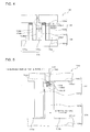
- Fig. 4 is a longitudinal sectional view illustrating an injection passage configuration of a compressor according to Comparative Example.
- Fig. 5 is an enlarged view of essential part of the injection passage configuration of the compressor according to Comparative Example.
- the structure of a scroll compressing unit 130 of the compressor according to Comparative Example will now be described with reference to Figs. 4 and 5 .
- the scroll compressing unit 130 includes a fixed scroll 103 and an orbiting scroll 104.
- the scroll compressing unit 130 includes therein a plurality of compression chambers 170.
- the compression chambers 170 will be described in detail later.
- the fixed scroll 103 includes a base plate 103a having a lap bottom surface 103a1 and a scroll lap 103b extending from a lower surface of the base plate 103a.
- the orbiting scroll 104 is a member that includes a base plate 104a having a lap bottom surface 104a1 and a scroll lap 104b extending from an upper surface of the base plate 104a.
- the scroll lap 103b has a scroll flank 103b1, a lap flank 103b2, and a tip facing the orbiting scroll 104.
- the scroll lap 104b has a scroll flank 104b1, a groove 104b2, and a tip facing the fixed scroll 103.
- the scroll lap 104b includes raised portions 104b3 defined by the groove 104b2.
- the groove 104b2 receives a seal 114.
- the fixed scroll 103 and the orbiting scroll 104 are arranged such that the scroll lap 103b and the scroll lap 104b engage with each other. Consequently, the lap bottom surface 103a1 faces the lap bottom surface 104a1 and the scroll flank 103b1 contacts the scroll flank 104b1, thus defining the compression chambers 170.
- the compression chambers 170 include a low pressure chamber 170a, an intermediate chamber 170b, and a high pressure chamber 170c in order of increasing pressure.
- the base plate 103a of the fixed scroll 103 has an injection passage 150 extending from a rear surface of the base plate 103a toward the scroll lap 103b.
- the injection passage 150 is formed so as to extend through the base plate 103a of the fixed scroll 103 from an upper surface of the base plate 103a to the lower surface thereof.
- the injection passage 150 is connected to an injection pipe 113 so that refrigerant can be directly injected into the intermediate chamber 170b. Since the base plate 103a has the injection passage 150 as described above, the base plate 103a has an opening port 103c in the lower surface.
- full-line arrows indicate a direction in which force acts on the seal 14.
- the orbiting scroll 4 orbits horizontally as illustrated in Fig. 5 .
- the seal 114 partially closes the injection passage 150 over an angle of substantially 90 degrees of orbital motion (360 degrees) of the orbiting scroll 104.
- the scroll lap 103b of the fixed scroll 103 defining the intermediate chamber 170b is located outside the opening port 103c.
- the force of an injection flow is applied to the seal 114 such that the seal 114 is hindered from floating. If the pressure of fluid injected and a pressure difference for sealing of the seal 114 are out of balance, floating force may fail, thus forming a clearance between the seal 114 and the lap bottom. Since part of the seal 114 facing the injection passage 150 is depressed, surrounding parts of the seal 114 are also depressed to form a clearance, causing loss of sealing. Unfortunately, compressed gas refrigerant may leak inside the compressor, causing loss of power.
- the seal 114 may enter the injection passage 150 depending on floating force of the seal 114.
- An edge of the injection passage 50 may damage and break the seal 114 depending on the relationship between the area of the injection passage 150 and the width of the seal 114.
- a method of reducing the opening area of the opening port 103c or a method of shaping the opening port 103c into, for example, an elongated hole by complicated machining without changing the opening area of the opening port 103c can be used so that the seal 114 is prevented from facing the opening port 103c (injection passage 150).
- any of these methods is undesirable in terms of workability, for example.
- the compressor 100 according to Embodiment 1 is configured such that the scroll lap 3b of the fixed scroll 3 defining the intermediate chamber 70b is at least partly located inside the opening port 3c in plan view of the fixed scroll 3. This can eliminate or reduce a likelihood that the seal 14 may close the injection passage 50 during one orbit of the orbiting scroll 4 relative to the fixed scroll 3.
- the compressor 100 according to Embodiment 1 achieves the elimination or reduction of the likelihood that the seal 14 may enter the injection passage 50, this can inhibit breakage of the compressor 100.
- the flow rate of injection can be maintained without the need for any complicated machining and without changing the pressure of injection.
- the fixed scroll 3 is typically machined from the rear surface with a rotary tool.
- the center of a drill bit of a rotary drill is located at a point located inwardly of the scroll flank in a thickness direction of the scroll lap. This can inhibit deviation of the drill bit, thus enhancing workability.
- the reason why the center of the drill bit of the rotary drill is located at a point located inwardly of the scroll flank in the thickness direction of the scroll lap is as follows.
- part of the rotary drill cutting the scroll lap is under load conditions and part thereof cutting nothing is under no-load conditions, so that the rotary drill tends to deviate to a no-load side.
- the rotary drill may fail to achieve machining with no deviation, and may be broken during machining.
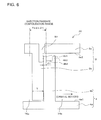
- Fig. 6 is an enlarged view of essential part of a range of the injection passage configuration of the compressor 100 according to Embodiment 1 of the present invention.
- the injection passage 50 is disposed in a range that satisfies (T + 2 ⁇ ⁇ 1), where T denotes the thickness of the scroll lap 3b of the fixed scroll 3 and ⁇ 1 denotes the thickness of the raised portion 4b3 of the orbiting scroll 4.
- Fig. 7 is an enlarged view of essential part of the positional relationship between the lap flank 3b2 and the center of a machined injection passage in the compressor 100 according to Embodiment 1 of the present invention.
- the injection passage 50 is circular in cross-section (transverse cross-section) parallel to the base plate 3a.
- the center of the circular cross-section is located within two curves obtained by projecting the flanks of the scroll lap 3b onto the base plate 3a.
- the injection passage 50 is formed so that a distance ⁇ 2 between the center of the circular cross-section and the lap flank 3b2 is positive.
Landscapes
- Engineering & Computer Science (AREA)
- Mechanical Engineering (AREA)
- General Engineering & Computer Science (AREA)
- Rotary Pumps (AREA)
- Applications Or Details Of Rotary Compressors (AREA)
Abstract
Description
- The present invention relates to a scroll compressor.
- In compressing gas refrigerant, the pressure of the refrigerant rises and the temperature thereof also rises. In a refrigeration cycle, the pressure is increased to a target high pressure. To eliminate or reduce a likelihood that the temperature will automatically rise too high, a method of injecting liquid refrigerant and using heat of evaporation of the refrigerant to reduce the temperature is used.
- A scroll compressor includes a fixed scroll including a base plate and a scroll lap and an orbiting scroll including a base plate and a scroll lap. The orbiting scroll is allowed to orbit. The scroll laps of the fixed scroll and the orbiting scroll engage with each other, thus defining compression chambers. The compression chambers include an intermediate chamber for reducing the volume of low pressure gas taken such that the pressure of the gas is increased to a target high pressure before the gas is discharged.
- Typically, the intermediate chamber is at an intermediate pressure between the low pressure of the taken refrigerant and the target high pressure. Low temperature, high pressure liquid refrigerant is injected into the intermediate chamber through an injection passage, thus reducing the temperature of the high pressure gas to be discharged from the compressor. Typically, the above-described injection passage extends through the base plate of the fixed scroll from a rear surface of the base plate toward the scroll lap of the fixed scroll.
- A known scroll compressor includes a fixed scroll, an orbiting scroll, and a seal for sealing a clearance between a lower surface (lap bottom) of a base plate of the fixed scroll and the tip of a scroll lap of the orbiting scroll (refer to
Patent Literature 1, for example). - Patent Literature 1:
Japanese Unexamined Patent Application Publication No. 10-37868 Fig. 4 ). - In the scroll compressor disclosed in
Patent Literature 1, when refrigerant is injected into an intermediate chamber, the seal may close at least part of an injection passage depending on the orbit angle of the orbiting scroll. - Furthermore, if the seal closes the injection passage, the seal may be depressed upon receiving a pressure caused by an injection flow. Disadvantageously, compressed gas may leak to a low-pressure side through a clearance formed by the seal, thus causing loss of compression.
- In particular, a compressor for low temperature purposes has a low suction pressure, resulting in a large difference between the suction pressure and the pressure in the intermediate chamber. The amount of compressed gas leaking through a clearance formed by the seal may accordingly be increased, thus causing the loss of compression.
- In addition, an edge of an opening port of the injection passage may damage the seal closing the injection passage. If such an action is repeated for a long period, the seal will wear and the compressed gas will leak, thus causing the loss of compression.
- In particular, under pressure conditions where an operation can be performed without injection, the seal may enter an injection hole. Disadvantageously, the seal may be broken into pieces and the pieces may be caught by compressing parts, thus causing a failure of the compressor.
- The present invention has been made in consideration of the above-described problems, and is directed to a scroll compressor capable of injecting refrigerant into an intermediate chamber without adversely affecting a sealing function of a seal.
- The present invention provides a scroll compressor including a sealed container, a fixed scroll that is disposed within the sealed container and includes a base plate and a scroll lap extending from a lower surface of the base plate, an orbiting scroll that is disposed within the sealed container and includes a base plate and a scroll lap extending from an upper surface of the base plate, a compression chamber defined by engagement of the scroll lap of the fixed scroll and the scroll lap of the orbiting scroll, and an injection passage that extends through the base plate of the fixed scroll from an upper surface of the base plate to the lower surface of the base plate and communicates with the compression chamber through an opening port. The scroll lap of the fixed scroll defining the compression chamber is at least partly located inside the opening port in plan view of the fixed scroll.
- According to the present invention, in plan view of the fixed scroll, the scroll lap of the fixed scroll defining the compression chamber is at least partly located inside the opening port. Consequently, refrigerant can be injected into an intermediate chamber without adversely affecting a sealing function of a seal. Brief Description of Drawings
-
- [
Fig. 1] Fig. 1 is a longitudinal sectional view of the configuration of acompressor 100 according toEmbodiment 1 of the present invention. - [
Fig. 2] Fig. 2 is a longitudinal sectional view illustrating an injection passage configuration of thecompressor 100 according toEmbodiment 1 of the present invention. - [
Fig. 3] Fig. 3 is an enlarged view of essential part of the injection passage configuration of thecompressor 100 according toEmbodiment 1 of the present invention. - [
Fig. 4] Fig. 4 is a longitudinal sectional view illustrating an injection passage configuration of a compressor according to Comparative Example. - [
Fig. 5] Fig. 5 is an enlarged view of essential part of the injection passage configuration of the compressor according to Comparative Example. - [
Fig. 6] Fig. 6 is an enlarged view of essential part illustrating a range of the injection passage configuration of thecompressor 100 according toEmbodiment 1 of the present invention. - [
Fig. 7] Fig. 7 is an enlarged view of essential part illustrating the positional relationship between a lap flank 3b2 and the center of a machined injection passage in thecompressor 100 according toEmbodiment 1 of the present invention. -
Fig. 1 is a longitudinal sectional view of the configuration of acompressor 100 according toEmbodiment 1 of the present invention.Fig. 2 is a longitudinal sectional view illustrating an injection passage configuration of thecompressor 100 according toEmbodiment 1 of the present invention.Fig. 3 is an enlarged view of essential part of the injection passage configuration of thecompressor 100 according toEmbodiment 1 of the present invention. -
Fig. 1 illustrates a typical internal structure of a scroll compressor. As illustrated inFig. 1 , thecompressor 100 includes a sealedcontainer 1, aframe 2, amain shaft 7, areservoir 8, a pump 9, aninjection pipe 13, ascroll compressing unit 30 disposed in upper part of thecompressor 100, amotor driving unit 40 disposed in middle part of thecompressor 100, and an Oldhamring 45. - The sealed
container 1 includes asuction pipe 10 through which gas refrigerant is taken into the sealedcontainer 1 and adischarge pipe 11 through which compressed gas refrigerant is discharged. Theframe 2 is a member for retaining afixed scroll 3, which will be described later. Themain shaft 7, which has therein an oil pump hole (not illustrated) extending axially, is a member for supplying oil to sliding parts. Thereservoir 8, which is disposed under themotor driving unit 40, is a space for storing lubricating oil. The pump 9, which is attached to a lower end of themain shaft 7, is a member for sucking up the lubricating oil stored in thereservoir 8. Theinjection pipe 13 is a pipe for supplying the refrigerant to thescroll compressing unit 30. Examples of the refrigerant to be injected include R22 and R32. - The
scroll compressing unit 30 includes thefixed scroll 3 including abase plate 3a (Fig. 2 ) retained by theframe 2 within the sealedcontainer 1 and anorbiting scroll 4 including abase plate 4a (Fig. 2 ). The orbitingscroll 4 is allowed to orbit. Thescroll compressing unit 30 includes therein a plurality of compression chambers 70 (Fig. 2 ). Thecompression chambers 70 will be described in detail later. - The
motor driving unit 40 includes a stator 5 fixed within the sealedcontainer 1 and arotor 6 fixed to themain shaft 7 so as to face the stator 5. Themain shaft 7 is engaged with a bearing on a rear surface of the orbiting scroll so that rotation power can be transmitted to the compressing unit. - The Oldham
ring 45 is disposed so as to engage with both a groove (not illustrated) on theframe 2 and a groove (not illustrated) on the rear surface of the orbitingscroll 4. This inhibits rotation of the orbitingscroll 4 and permits only orbital motion of the orbitingscroll 4. - An operation will now be described.
- When power is supplied to the stator 5 from an external power supply, the
rotor 6 rotates, so that power is transmitted to theorbiting scroll 4 through themain shaft 7. The orbitingscroll 4, whose rotation is inhibited by the Oldhamring 45, accordingly starts orbital motion. - The gas refrigerant sucked through the
suction pipe 10 is successively taken into thecompression chambers 70. Suction, compression, and discharge are repeated. The lubricating oil stored in thereservoir 8 is pumped by rotation of themain shaft 7 and is then supplied to the sliding parts. After that, the lubricating oil returns to the lower part of the sealedcontainer 1. - When the temperature of the gas refrigerant to be discharged is high, liquid refrigerant is injected into an
intermediate chamber 70b through theinjection pipe 13. Typically, the liquid refrigerant to be injected is at a higher pressure than thetarget compression chamber 70. The injection is achieved using a pressure difference. - As illustrated in
Fig. 2 , thescroll compressing unit 30 includes the fixedscroll 3 and theorbiting scroll 4. The fixedscroll 3 includes thebase plate 3a having a lap bottom surface 3a1 and ascroll lap 3b extending from a lower surface (lap bottom surface 3a1) of thebase plate 3a. Theorbiting scroll 4 includes thebase plate 4a having a lap bottom surface 4a1 and ascroll lap 4b extending from an upper surface (lap bottom surface 4a1) of thebase plate 4a. InFig. 2 , a dotted-line arrow indicates a refrigerant injection direction. - The
scroll lap 3b has a scroll flank 3b1, a lap flank 3b2, and a tip facing theorbiting scroll 4. Thescroll lap 4b has a scroll flank 4b1, a groove 4b2, and a tip facing the fixedscroll 3. The groove 4b2 is longitudinally recessed from the tip of thescroll lap 4b of theorbiting scroll 4 toward a base of thescroll lap 4b. Thescroll lap 4b includes raised portions 4b3 defined by the groove 4b2. The groove 4b2 receives aseal 14. - The fixed
scroll 3 and theorbiting scroll 4 are combined such that thescroll lap 3b and thescroll lap 4b engage with each other. Consequently, the lap bottom surface 3a1 faces the lap bottom surface 4a1 and the scroll flank 3b1 contacts the scroll flank 4b1, thus defining thecompression chambers 70. Thecompression chambers 70 include alow pressure chamber 70a, theintermediate chamber 70b, and ahigh pressure chamber 70c in order of increasing pressure. - The
seal 14 is a sealing member that automatically floats due to the pressure difference between the adjacent compression chambers after compression starts and comes into continuous contact with the lap bottom surface of the opposing scroll to achieve sealing. Theseal 14, which is received in the groove 4b2, is a member movable between the groove 4b2 and the lower surface (lap bottom surface 3a1) of thebase plate 3a of the fixedscroll 3. Theseal 14 in the groove 4b2 of theorbiting scroll 4 hermetically seals thecompression chambers 70. - As illustrated in
Fig. 3 , thebase plate 3a of the fixedscroll 3 has aninjection passage 50 extending from a rear surface of thebase plate 3a to thescroll lap 3b. In other words, theinjection passage 50 is formed so as to extend through thebase plate 3a of the fixedscroll 3 from an upper surface of thebase plate 3a to the lower surface thereof. Theinjection passage 50 is connected to theinjection pipe 13 so that the refrigerant can be directly injected into theintermediate chamber 70b. Since thebase plate 3a has theinjection passage 50 as described above, thebase plate 3a has anopening port 3c in the lower surface. InFig. 3 , full-line arrows indicate a direction in which force acts on theseal 14. In addition, theorbiting scroll 4 orbits horizontally as illustrated inFig. 3 . - In plan view of the fixed
scroll 3, thescroll lap 3b of the fixedscroll 3 defining theintermediate chamber 70b is at least partly located inside theopening port 3c. Furthermore, an inner side surface of the raised portion 4b3 located adjacent to theinjection passage 50 is located outside theopening port 3c. -
Fig. 4 is a longitudinal sectional view illustrating an injection passage configuration of a compressor according to Comparative Example.Fig. 5 is an enlarged view of essential part of the injection passage configuration of the compressor according to Comparative Example. The structure of ascroll compressing unit 130 of the compressor according to Comparative Example will now be described with reference toFigs. 4 and 5 . - As illustrated in
Fig. 4 , thescroll compressing unit 130 includes a fixedscroll 103 and anorbiting scroll 104. Thescroll compressing unit 130 includes therein a plurality ofcompression chambers 170. Thecompression chambers 170 will be described in detail later. - The fixed
scroll 103 includes abase plate 103a having a lap bottom surface 103a1 and ascroll lap 103b extending from a lower surface of thebase plate 103a. Theorbiting scroll 104 is a member that includes abase plate 104a having a lap bottom surface 104a1 and ascroll lap 104b extending from an upper surface of thebase plate 104a. - The
scroll lap 103b has a scroll flank 103b1, a lap flank 103b2, and a tip facing theorbiting scroll 104. Thescroll lap 104b has a scroll flank 104b1, a groove 104b2, and a tip facing the fixedscroll 103. Thescroll lap 104b includes raised portions 104b3 defined by the groove 104b2. The groove 104b2 receives aseal 114. - The fixed
scroll 103 and theorbiting scroll 104 are arranged such that thescroll lap 103b and thescroll lap 104b engage with each other. Consequently, the lap bottom surface 103a1 faces the lap bottom surface 104a1 and the scroll flank 103b1 contacts the scroll flank 104b1, thus defining thecompression chambers 170. Thecompression chambers 170 include alow pressure chamber 170a, anintermediate chamber 170b, and ahigh pressure chamber 170c in order of increasing pressure. - As illustrated in
Fig. 5 , thebase plate 103a of the fixedscroll 103 has aninjection passage 150 extending from a rear surface of thebase plate 103a toward thescroll lap 103b. In other words, theinjection passage 150 is formed so as to extend through thebase plate 103a of the fixedscroll 103 from an upper surface of thebase plate 103a to the lower surface thereof. Theinjection passage 150 is connected to aninjection pipe 113 so that refrigerant can be directly injected into theintermediate chamber 170b. Since thebase plate 103a has theinjection passage 150 as described above, thebase plate 103a has anopening port 103c in the lower surface. InFig. 5 , full-line arrows indicate a direction in which force acts on theseal 14. In addition, theorbiting scroll 4 orbits horizontally as illustrated inFig. 5 . - When the fixed
scroll 103 and theorbiting scroll 104 are located as illustrated inFig. 5 , theseal 114 partially closes theinjection passage 150 over an angle of substantially 90 degrees of orbital motion (360 degrees) of theorbiting scroll 104. The reason is because, in plan view of the fixedscroll 103, thescroll lap 103b of the fixedscroll 103 defining theintermediate chamber 170b is located outside theopening port 103c. - As described above, when at least part of the
seal 114 is located so as to face theinjection passage 150 during the orbital motion of theorbiting scroll 104, the force of an injection flow is applied to theseal 114 such that theseal 114 is hindered from floating. If the pressure of fluid injected and a pressure difference for sealing of theseal 114 are out of balance, floating force may fail, thus forming a clearance between theseal 114 and the lap bottom. Since part of theseal 114 facing theinjection passage 150 is depressed, surrounding parts of theseal 114 are also depressed to form a clearance, causing loss of sealing. Unfortunately, compressed gas refrigerant may leak inside the compressor, causing loss of power. - Furthermore, under pressure conditions where injection is not used, the
seal 114 may enter theinjection passage 150 depending on floating force of theseal 114. An edge of theinjection passage 50 may damage and break theseal 114 depending on the relationship between the area of theinjection passage 150 and the width of theseal 114. - For example, a method of reducing the opening area of the
opening port 103c or a method of shaping theopening port 103c into, for example, an elongated hole by complicated machining without changing the opening area of theopening port 103c can be used so that theseal 114 is prevented from facing theopening port 103c (injection passage 150). However, any of these methods is undesirable in terms of workability, for example. - In contrast, the
compressor 100 according toEmbodiment 1 is configured such that thescroll lap 3b of the fixedscroll 3 defining theintermediate chamber 70b is at least partly located inside theopening port 3c in plan view of the fixedscroll 3. This can eliminate or reduce a likelihood that theseal 14 may close theinjection passage 50 during one orbit of theorbiting scroll 4 relative to the fixedscroll 3. - This can inhibit inside leakage through a sealing clearance that is formed due to 90-degree displacement of the floating direction of the
seal 14 relative to the fluid pressure acting direction of the injection flow. Consequently, the refrigerant can be injected into theintermediate chamber 70b without adversely affecting the sealing function of theseal 14. - Additionally, since the
compressor 100 according toEmbodiment 1 achieves the elimination or reduction of the likelihood that theseal 14 may enter theinjection passage 50, this can inhibit breakage of thecompressor 100. Thus, the flow rate of injection can be maintained without the need for any complicated machining and without changing the pressure of injection. - Furthermore, in the
compressor 100 according toEmbodiment 1, if a sliding surface of theseal 14 and the lap flank 3b2 of the fixedscroll 3 are at a short distance from each other, a necessary flow rate of injection can be achieved. Additionally, interference between the openingport 3c and theseal 14 can be eliminated or reduced under non-injection conditions, thus achieving reliability without any damage to theseal 14. - To allow the
injection passage 50 to be substantially circular in cross-section, the fixedscroll 3 is typically machined from the rear surface with a rotary tool. To machine the fixedscroll 3 so that thescroll lap 3b of the fixedscroll 3 defining thecompression chamber 70 is at least partly located inside theopening port 3c in plan view of the fixedscroll 3 as inEmbodiment 1, the center of a drill bit of a rotary drill is located at a point located inwardly of the scroll flank in a thickness direction of the scroll lap. This can inhibit deviation of the drill bit, thus enhancing workability. The reason why the center of the drill bit of the rotary drill is located at a point located inwardly of the scroll flank in the thickness direction of the scroll lap is as follows. When the drill bit extending through thebase plate 3a reaches the scroll flank 3b1 to machine part of the flank, part of the rotary drill cutting the scroll lap is under load conditions and part thereof cutting nothing is under no-load conditions, so that the rotary drill tends to deviate to a no-load side. The rotary drill may fail to achieve machining with no deviation, and may be broken during machining. -
Fig. 6 is an enlarged view of essential part of a range of the injection passage configuration of thecompressor 100 according toEmbodiment 1 of the present invention. Referring toFig. 6 , theinjection passage 50 is disposed in a range that satisfies (T + 2 × δ1), where T denotes the thickness of thescroll lap 3b of the fixedscroll 3 and δ1 denotes the thickness of the raised portion 4b3 of theorbiting scroll 4. -
Fig. 7 is an enlarged view of essential part of the positional relationship between the lap flank 3b2 and the center of a machined injection passage in thecompressor 100 according toEmbodiment 1 of the present invention. As illustrated inFig. 7 , theinjection passage 50 is circular in cross-section (transverse cross-section) parallel to thebase plate 3a. The center of the circular cross-section is located within two curves obtained by projecting the flanks of thescroll lap 3b onto thebase plate 3a. Furthermore, theinjection passage 50 is formed so that a distance δ2 between the center of the circular cross-section and the lap flank 3b2 is positive. - In particular, products are now designed to have higher performance. This increases the need for thinner scroll laps made of high-strength materials to reduce leakage loss caused by a pressure difference between adjacent compression chambers. As the scroll laps are thinner, a seal is also reduced in width. The present invention, therefore, can eliminate a risk that a narrower seal enters an injection hole, which has to have an appropriate size as a passage. Furthermore, the recent trend of refrigerant to be used is toward refrigerants (e.g., R32 and 1,1,2-trifluoroethylene) easier to increase in temperature and pressure during compression than conventional refrigerants. The present invention, therefore, can eliminate or reduce an increase in leakage loss caused by an increase in flow rate of injection as well as an increased pressure difference between adjacent compression chambers. Reference Signs List
- 1: sealed container; 2: frame; 3: fixed scroll; 3a: base plate; 3a1: lap bottom surface; 3b: scroll lap; 3b1: scroll flank; 3b2: lap flank; 3c: opening port; 4: orbiting scroll; 4a: base plate; 4a1: lap bottom surface; 4b: scroll lap; 4b1: scroll flank; 4b2: groove; 4b3: raised portion; 5: stator; 6: rotor; 7: main shaft; 8: reservoir; 9: pump; 10: suction pipe; 11: discharge pipe; 13: injection pipe; 14: seal; 30: scroll compressing unit; 40: motor driving unit; 45: Oldham ring; 50: injection passage; 70: compression chamber; 70a: low pressure chamber; 70b: intermediate chamber; 70c: high pressure chamber; 100: compressor; 103: fixed scroll; 103a: base plate; 103a1: lap bottom surface; 103b: scroll lap; 103b1: scroll flank; 103b2: lap flank; 103c: opening port; 104: orbiting scroll; 104a: base plate; 104a1: lap bottom surface; 104b: scroll lap; 104b1: scroll flank; 104b2: groove; 104b3: raised portion; 113: injection pipe; 114: seal; 130: scroll compressing unit; 150: injection passage; 170: compression chamber; 170a: low pressure chamber; 170b: intermediate chamber; 170c: high pressure chamber; T: thickness; δ1: thickness: and δ2: distance.
Claims (4)
- A scroll compressor comprising:a sealed container;a fixed scroll disposed within the sealed container, the fixed scroll including a base plate and a scroll lap extending from a lower surface of the base plate;an orbiting scroll disposed within the sealed container, the orbiting scroll including a base plate and a scroll lap extending from an upper surface of the base plate;a compression chamber defined by engagement of the scroll lap of the fixed scroll and the scroll lap of the orbiting scroll; andan injection passage extending through the base plate of the fixed scroll from an upper surface of the base plate to the lower surface of the base plate, the injection passage communicating with the compression chamber through an opening port,the scroll lap of the fixed scroll defining the compression chamber being at least partly located inside the opening port in plan view of the fixed scroll.
- The scroll compressor of claim 1,
wherein the scroll lap of the orbiting scroll has a groove longitudinally recessed from a tip of the scroll lap toward a base of the scroll lap, and includes raised portions defined by the groove,
wherein the scroll compressor further includes a seal received in the groove, and the seal is movable between the groove and the lower surface of the base plate of the fixed scroll, and
one of the raised portions adjacent to the injection passage is disposed such that an inner side surface of the raised portion is located outside the opening port. - The scroll compressor of claim 1 or 2,
wherein the injection passage has a substantially circular transverse cross-section, and
wherein the substantially circular transverse cross-section has a center located within two curves obtained by projecting flanks of the scroll lap onto the base plate. - The scroll compressor of any one of claims 1 to 3, wherein refrigerant used is R32 or 1,1,2-trifluoroethylene.
Applications Claiming Priority (1)
| Application Number | Priority Date | Filing Date | Title |
|---|---|---|---|
| PCT/JP2014/051206 WO2015111146A1 (en) | 2014-01-22 | 2014-01-22 | Scroll compressor |
Publications (3)
| Publication Number | Publication Date |
|---|---|
| EP3098451A1 true EP3098451A1 (en) | 2016-11-30 |
| EP3098451A4 EP3098451A4 (en) | 2019-05-01 |
| EP3098451B1 EP3098451B1 (en) | 2020-05-27 |
Family
ID=53680978
Family Applications (1)
| Application Number | Title | Priority Date | Filing Date |
|---|---|---|---|
| EP14879980.2A Active EP3098451B1 (en) | 2014-01-22 | 2014-01-22 | Scroll compressor |
Country Status (6)
| Country | Link |
|---|---|
| US (1) | US10451069B2 (en) |
| EP (1) | EP3098451B1 (en) |
| JP (1) | JP6109344B2 (en) |
| CN (1) | CN105874204B (en) |
| CA (1) | CA2933146C (en) |
| WO (1) | WO2015111146A1 (en) |
Families Citing this family (1)
| Publication number | Priority date | Publication date | Assignee | Title |
|---|---|---|---|---|
| CN110360105B (en) * | 2019-07-24 | 2024-04-05 | 珠海格力节能环保制冷技术研究中心有限公司 | Compressor with radial seal structure |
Family Cites Families (19)
| Publication number | Priority date | Publication date | Assignee | Title |
|---|---|---|---|---|
| AU547490B2 (en) * | 1980-05-31 | 1985-10-24 | Sanden Corporation | Scroll-type pump |
| JPS6128782A (en) * | 1984-07-20 | 1986-02-08 | Toshiba Corp | Scroll compressor |
| EP0326189B1 (en) * | 1985-08-10 | 1991-12-11 | Sanden Corporation | Scroll type compressor with variable displacement mechanism |
| JP2501182B2 (en) * | 1995-03-13 | 1996-05-29 | 株式会社日立製作所 | Refrigeration equipment |
| JP3371603B2 (en) * | 1995-04-17 | 2003-01-27 | 松下電器産業株式会社 | Scroll compressor |
| JPH1037868A (en) | 1996-07-19 | 1998-02-13 | Matsushita Electric Ind Co Ltd | Scroll compressor |
| JP3874469B2 (en) * | 1996-10-04 | 2007-01-31 | 株式会社日立製作所 | Scroll compressor |
| US6196816B1 (en) * | 1998-08-17 | 2001-03-06 | Carrier Corporation | Unequal injection ports for scroll compressors |
| JP4265128B2 (en) * | 2001-10-10 | 2009-05-20 | 株式会社日立製作所 | Scroll compressor and air conditioner |
| JP3918814B2 (en) * | 2004-01-15 | 2007-05-23 | ダイキン工業株式会社 | Fluid machinery |
| JP4385917B2 (en) | 2004-10-18 | 2009-12-16 | パナソニック株式会社 | Scroll compressor |
| JP4584306B2 (en) | 2005-03-29 | 2010-11-17 | 三菱電機株式会社 | Scroll expander |
| JP4660335B2 (en) * | 2005-09-30 | 2011-03-30 | 三洋電機株式会社 | Scroll compressor |
| US7674098B2 (en) * | 2006-11-07 | 2010-03-09 | Scroll Technologies | Scroll compressor with vapor injection and unloader port |
| US7901194B2 (en) * | 2008-04-09 | 2011-03-08 | Hamilton Sundstrand Corporation | Shaft coupling for scroll compressor |
| JP5314326B2 (en) | 2008-05-30 | 2013-10-16 | 三菱重工業株式会社 | Refrigerant compressor |
| CN201953655U (en) * | 2010-12-31 | 2011-08-31 | 丹佛斯(天津)有限公司 | Scroll compressor |
| JP2012247105A (en) * | 2011-05-26 | 2012-12-13 | Sanyo Electric Co Ltd | Cryogenic refrigerator with scroll compressor |
| JP5984377B2 (en) | 2011-12-22 | 2016-09-06 | 三菱重工業株式会社 | Scroll compressor |
-
2014
- 2014-01-22 JP JP2015558629A patent/JP6109344B2/en active Active
- 2014-01-22 CA CA2933146A patent/CA2933146C/en active Active
- 2014-01-22 EP EP14879980.2A patent/EP3098451B1/en active Active
- 2014-01-22 CN CN201480072375.7A patent/CN105874204B/en active Active
- 2014-01-22 US US15/101,500 patent/US10451069B2/en active Active
- 2014-01-22 WO PCT/JP2014/051206 patent/WO2015111146A1/en not_active Ceased
Also Published As
| Publication number | Publication date |
|---|---|
| EP3098451B1 (en) | 2020-05-27 |
| CA2933146C (en) | 2017-08-15 |
| US10451069B2 (en) | 2019-10-22 |
| JPWO2015111146A1 (en) | 2017-03-23 |
| CN105874204A (en) | 2016-08-17 |
| JP6109344B2 (en) | 2017-04-05 |
| WO2015111146A1 (en) | 2015-07-30 |
| CA2933146A1 (en) | 2015-07-30 |
| US20160319818A1 (en) | 2016-11-03 |
| EP3098451A4 (en) | 2019-05-01 |
| CN105874204B (en) | 2018-06-01 |
Similar Documents
| Publication | Publication Date | Title |
|---|---|---|
| US7229261B2 (en) | Scroll compressor having an annular recess located outside an annular seal portion and another recess communicating with suction port of fixed scroll | |
| US9903370B2 (en) | Scroll compressor with reduced upsetting moment | |
| EP3263900B1 (en) | Scroll-type compressor | |
| KR101300261B1 (en) | Scroll compressor | |
| US9011120B2 (en) | Scroll compressor with bearing grooves on both sides of key groove | |
| JP5304285B2 (en) | Scroll compressor | |
| KR101101593B1 (en) | Scroll compressor | |
| CA2933146C (en) | Scroll compressor | |
| US11725656B2 (en) | Scroll compressor including a fixed-side first region receiving a force which presses a movable scroll against a moveable scroll against a fixed scroll | |
| EP3388672B1 (en) | Scroll compressor | |
| KR20110064667A (en) | Scroll compressor | |
| JP5278228B2 (en) | Scroll compressor | |
| KR20150126534A (en) | Scroll compressor | |
| US10082140B2 (en) | Scroll compressor having compression chamber communicating with discharge port via a gap between recessed part formed on front face of movable-side plate and tip of fixed-side lap | |
| WO2022038730A1 (en) | Scroll compressor | |
| CN113316687B (en) | Scroll compressor having a discharge port | |
| US20240418167A1 (en) | Compressor | |
| JP2007182870A (en) | Scroll compressor | |
| KR20060065907A (en) | Tip seal structure of scroll compressor | |
| JP2009008008A (en) | Scroll compressor | |
| WO2021124973A1 (en) | Scroll compressor | |
| JP2006283770A (en) | Hermetic electric compressor | |
| JP2006291763A (en) | Scroll compressor | |
| JP2019019772A (en) | Scroll compressor |
Legal Events
| Date | Code | Title | Description |
|---|---|---|---|
| PUAI | Public reference made under article 153(3) epc to a published international application that has entered the european phase |
Free format text: ORIGINAL CODE: 0009012 |
|
| 17P | Request for examination filed |
Effective date: 20160615 |
|
| AK | Designated contracting states |
Kind code of ref document: A1 Designated state(s): AL AT BE BG CH CY CZ DE DK EE ES FI FR GB GR HR HU IE IS IT LI LT LU LV MC MK MT NL NO PL PT RO RS SE SI SK SM TR |
|
| AX | Request for extension of the european patent |
Extension state: BA ME |
|
| DAX | Request for extension of the european patent (deleted) | ||
| A4 | Supplementary search report drawn up and despatched |
Effective date: 20190403 |
|
| RIC1 | Information provided on ipc code assigned before grant |
Ipc: F04C 23/00 20060101ALI20190328BHEP Ipc: F04C 29/12 20060101ALI20190328BHEP Ipc: F04C 18/02 20060101AFI20190328BHEP Ipc: F04C 29/00 20060101ALI20190328BHEP Ipc: F04C 27/00 20060101ALI20190328BHEP |
|
| GRAP | Despatch of communication of intention to grant a patent |
Free format text: ORIGINAL CODE: EPIDOSNIGR1 |
|
| RIC1 | Information provided on ipc code assigned before grant |
Ipc: F04C 29/00 20060101ALI20191211BHEP Ipc: F04C 29/12 20060101ALI20191211BHEP Ipc: F04C 23/00 20060101ALI20191211BHEP Ipc: F04C 27/00 20060101ALI20191211BHEP Ipc: F04C 18/02 20060101AFI20191211BHEP |
|
| STAA | Information on the status of an ep patent application or granted ep patent |
Free format text: STATUS: GRANT OF PATENT IS INTENDED |
|
| INTG | Intention to grant announced |
Effective date: 20200116 |
|
| GRAS | Grant fee paid |
Free format text: ORIGINAL CODE: EPIDOSNIGR3 |
|
| GRAA | (expected) grant |
Free format text: ORIGINAL CODE: 0009210 |
|
| STAA | Information on the status of an ep patent application or granted ep patent |
Free format text: STATUS: THE PATENT HAS BEEN GRANTED |
|
| AK | Designated contracting states |
Kind code of ref document: B1 Designated state(s): AL AT BE BG CH CY CZ DE DK EE ES FI FR GB GR HR HU IE IS IT LI LT LU LV MC MK MT NL NO PL PT RO RS SE SI SK SM TR |
|
| REG | Reference to a national code |
Ref country code: GB Ref legal event code: FG4D |
|
| REG | Reference to a national code |
Ref country code: CH Ref legal event code: EP |
|
| REG | Reference to a national code |
Ref country code: AT Ref legal event code: REF Ref document number: 1274823 Country of ref document: AT Kind code of ref document: T Effective date: 20200615 |
|
| REG | Reference to a national code |
Ref country code: DE Ref legal event code: R096 Ref document number: 602014066060 Country of ref document: DE |
|
| REG | Reference to a national code |
Ref country code: LT Ref legal event code: MG4D |
|
| PG25 | Lapsed in a contracting state [announced via postgrant information from national office to epo] |
Ref country code: LT Free format text: LAPSE BECAUSE OF FAILURE TO SUBMIT A TRANSLATION OF THE DESCRIPTION OR TO PAY THE FEE WITHIN THE PRESCRIBED TIME-LIMIT Effective date: 20200527 Ref country code: SE Free format text: LAPSE BECAUSE OF FAILURE TO SUBMIT A TRANSLATION OF THE DESCRIPTION OR TO PAY THE FEE WITHIN THE PRESCRIBED TIME-LIMIT Effective date: 20200527 Ref country code: PT Free format text: LAPSE BECAUSE OF FAILURE TO SUBMIT A TRANSLATION OF THE DESCRIPTION OR TO PAY THE FEE WITHIN THE PRESCRIBED TIME-LIMIT Effective date: 20200928 Ref country code: FI Free format text: LAPSE BECAUSE OF FAILURE TO SUBMIT A TRANSLATION OF THE DESCRIPTION OR TO PAY THE FEE WITHIN THE PRESCRIBED TIME-LIMIT Effective date: 20200527 Ref country code: IS Free format text: LAPSE BECAUSE OF FAILURE TO SUBMIT A TRANSLATION OF THE DESCRIPTION OR TO PAY THE FEE WITHIN THE PRESCRIBED TIME-LIMIT Effective date: 20200927 Ref country code: NO Free format text: LAPSE BECAUSE OF FAILURE TO SUBMIT A TRANSLATION OF THE DESCRIPTION OR TO PAY THE FEE WITHIN THE PRESCRIBED TIME-LIMIT Effective date: 20200827 Ref country code: GR Free format text: LAPSE BECAUSE OF FAILURE TO SUBMIT A TRANSLATION OF THE DESCRIPTION OR TO PAY THE FEE WITHIN THE PRESCRIBED TIME-LIMIT Effective date: 20200828 |
|
| REG | Reference to a national code |
Ref country code: NL Ref legal event code: MP Effective date: 20200527 |
|
| PG25 | Lapsed in a contracting state [announced via postgrant information from national office to epo] |
Ref country code: HR Free format text: LAPSE BECAUSE OF FAILURE TO SUBMIT A TRANSLATION OF THE DESCRIPTION OR TO PAY THE FEE WITHIN THE PRESCRIBED TIME-LIMIT Effective date: 20200527 Ref country code: LV Free format text: LAPSE BECAUSE OF FAILURE TO SUBMIT A TRANSLATION OF THE DESCRIPTION OR TO PAY THE FEE WITHIN THE PRESCRIBED TIME-LIMIT Effective date: 20200527 Ref country code: RS Free format text: LAPSE BECAUSE OF FAILURE TO SUBMIT A TRANSLATION OF THE DESCRIPTION OR TO PAY THE FEE WITHIN THE PRESCRIBED TIME-LIMIT Effective date: 20200527 Ref country code: BG Free format text: LAPSE BECAUSE OF FAILURE TO SUBMIT A TRANSLATION OF THE DESCRIPTION OR TO PAY THE FEE WITHIN THE PRESCRIBED TIME-LIMIT Effective date: 20200827 |
|
| REG | Reference to a national code |
Ref country code: AT Ref legal event code: MK05 Ref document number: 1274823 Country of ref document: AT Kind code of ref document: T Effective date: 20200527 |
|
| PG25 | Lapsed in a contracting state [announced via postgrant information from national office to epo] |
Ref country code: AL Free format text: LAPSE BECAUSE OF FAILURE TO SUBMIT A TRANSLATION OF THE DESCRIPTION OR TO PAY THE FEE WITHIN THE PRESCRIBED TIME-LIMIT Effective date: 20200527 Ref country code: NL Free format text: LAPSE BECAUSE OF FAILURE TO SUBMIT A TRANSLATION OF THE DESCRIPTION OR TO PAY THE FEE WITHIN THE PRESCRIBED TIME-LIMIT Effective date: 20200527 |
|
| PG25 | Lapsed in a contracting state [announced via postgrant information from national office to epo] |
Ref country code: RO Free format text: LAPSE BECAUSE OF FAILURE TO SUBMIT A TRANSLATION OF THE DESCRIPTION OR TO PAY THE FEE WITHIN THE PRESCRIBED TIME-LIMIT Effective date: 20200527 Ref country code: CZ Free format text: LAPSE BECAUSE OF FAILURE TO SUBMIT A TRANSLATION OF THE DESCRIPTION OR TO PAY THE FEE WITHIN THE PRESCRIBED TIME-LIMIT Effective date: 20200527 Ref country code: IT Free format text: LAPSE BECAUSE OF FAILURE TO SUBMIT A TRANSLATION OF THE DESCRIPTION OR TO PAY THE FEE WITHIN THE PRESCRIBED TIME-LIMIT Effective date: 20200527 Ref country code: DK Free format text: LAPSE BECAUSE OF FAILURE TO SUBMIT A TRANSLATION OF THE DESCRIPTION OR TO PAY THE FEE WITHIN THE PRESCRIBED TIME-LIMIT Effective date: 20200527 Ref country code: SM Free format text: LAPSE BECAUSE OF FAILURE TO SUBMIT A TRANSLATION OF THE DESCRIPTION OR TO PAY THE FEE WITHIN THE PRESCRIBED TIME-LIMIT Effective date: 20200527 Ref country code: EE Free format text: LAPSE BECAUSE OF FAILURE TO SUBMIT A TRANSLATION OF THE DESCRIPTION OR TO PAY THE FEE WITHIN THE PRESCRIBED TIME-LIMIT Effective date: 20200527 Ref country code: AT Free format text: LAPSE BECAUSE OF FAILURE TO SUBMIT A TRANSLATION OF THE DESCRIPTION OR TO PAY THE FEE WITHIN THE PRESCRIBED TIME-LIMIT Effective date: 20200527 Ref country code: ES Free format text: LAPSE BECAUSE OF FAILURE TO SUBMIT A TRANSLATION OF THE DESCRIPTION OR TO PAY THE FEE WITHIN THE PRESCRIBED TIME-LIMIT Effective date: 20200527 |
|
| PG25 | Lapsed in a contracting state [announced via postgrant information from national office to epo] |
Ref country code: SK Free format text: LAPSE BECAUSE OF FAILURE TO SUBMIT A TRANSLATION OF THE DESCRIPTION OR TO PAY THE FEE WITHIN THE PRESCRIBED TIME-LIMIT Effective date: 20200527 Ref country code: PL Free format text: LAPSE BECAUSE OF FAILURE TO SUBMIT A TRANSLATION OF THE DESCRIPTION OR TO PAY THE FEE WITHIN THE PRESCRIBED TIME-LIMIT Effective date: 20200527 |
|
| REG | Reference to a national code |
Ref country code: DE Ref legal event code: R097 Ref document number: 602014066060 Country of ref document: DE |
|
| PLBE | No opposition filed within time limit |
Free format text: ORIGINAL CODE: 0009261 |
|
| STAA | Information on the status of an ep patent application or granted ep patent |
Free format text: STATUS: NO OPPOSITION FILED WITHIN TIME LIMIT |
|
| 26N | No opposition filed |
Effective date: 20210302 |
|
| PG25 | Lapsed in a contracting state [announced via postgrant information from national office to epo] |
Ref country code: SI Free format text: LAPSE BECAUSE OF FAILURE TO SUBMIT A TRANSLATION OF THE DESCRIPTION OR TO PAY THE FEE WITHIN THE PRESCRIBED TIME-LIMIT Effective date: 20200527 |
|
| PG25 | Lapsed in a contracting state [announced via postgrant information from national office to epo] |
Ref country code: MC Free format text: LAPSE BECAUSE OF FAILURE TO SUBMIT A TRANSLATION OF THE DESCRIPTION OR TO PAY THE FEE WITHIN THE PRESCRIBED TIME-LIMIT Effective date: 20200527 |
|
| REG | Reference to a national code |
Ref country code: CH Ref legal event code: PL |
|
| PG25 | Lapsed in a contracting state [announced via postgrant information from national office to epo] |
Ref country code: LU Free format text: LAPSE BECAUSE OF NON-PAYMENT OF DUE FEES Effective date: 20210122 |
|
| REG | Reference to a national code |
Ref country code: BE Ref legal event code: MM Effective date: 20210131 |
|
| PG25 | Lapsed in a contracting state [announced via postgrant information from national office to epo] |
Ref country code: FR Free format text: LAPSE BECAUSE OF NON-PAYMENT OF DUE FEES Effective date: 20210131 |
|
| PG25 | Lapsed in a contracting state [announced via postgrant information from national office to epo] |
Ref country code: LI Free format text: LAPSE BECAUSE OF NON-PAYMENT OF DUE FEES Effective date: 20210131 Ref country code: CH Free format text: LAPSE BECAUSE OF NON-PAYMENT OF DUE FEES Effective date: 20210131 |
|
| PG25 | Lapsed in a contracting state [announced via postgrant information from national office to epo] |
Ref country code: IE Free format text: LAPSE BECAUSE OF NON-PAYMENT OF DUE FEES Effective date: 20210122 |
|
| PG25 | Lapsed in a contracting state [announced via postgrant information from national office to epo] |
Ref country code: BE Free format text: LAPSE BECAUSE OF NON-PAYMENT OF DUE FEES Effective date: 20210131 |
|
| REG | Reference to a national code |
Ref country code: DE Ref legal event code: R084 Ref document number: 602014066060 Country of ref document: DE |
|
| REG | Reference to a national code |
Ref country code: GB Ref legal event code: 746 Effective date: 20230103 |
|
| PG25 | Lapsed in a contracting state [announced via postgrant information from national office to epo] |
Ref country code: HU Free format text: LAPSE BECAUSE OF FAILURE TO SUBMIT A TRANSLATION OF THE DESCRIPTION OR TO PAY THE FEE WITHIN THE PRESCRIBED TIME-LIMIT; INVALID AB INITIO Effective date: 20140122 |
|
| P01 | Opt-out of the competence of the unified patent court (upc) registered |
Effective date: 20230512 |
|
| PG25 | Lapsed in a contracting state [announced via postgrant information from national office to epo] |
Ref country code: CY Free format text: LAPSE BECAUSE OF FAILURE TO SUBMIT A TRANSLATION OF THE DESCRIPTION OR TO PAY THE FEE WITHIN THE PRESCRIBED TIME-LIMIT Effective date: 20200527 |
|
| PGFP | Annual fee paid to national office [announced via postgrant information from national office to epo] |
Ref country code: GB Payment date: 20231130 Year of fee payment: 11 |
|
| PG25 | Lapsed in a contracting state [announced via postgrant information from national office to epo] |
Ref country code: MK Free format text: LAPSE BECAUSE OF FAILURE TO SUBMIT A TRANSLATION OF THE DESCRIPTION OR TO PAY THE FEE WITHIN THE PRESCRIBED TIME-LIMIT Effective date: 20200527 |
|
| PG25 | Lapsed in a contracting state [announced via postgrant information from national office to epo] |
Ref country code: MT Free format text: LAPSE BECAUSE OF FAILURE TO SUBMIT A TRANSLATION OF THE DESCRIPTION OR TO PAY THE FEE WITHIN THE PRESCRIBED TIME-LIMIT Effective date: 20200527 |
|
| PGFP | Annual fee paid to national office [announced via postgrant information from national office to epo] |
Ref country code: DE Payment date: 20241203 Year of fee payment: 12 |
|
| GBPC | Gb: european patent ceased through non-payment of renewal fee |
Effective date: 20250122 |
|
| PG25 | Lapsed in a contracting state [announced via postgrant information from national office to epo] |
Ref country code: GB Free format text: LAPSE BECAUSE OF NON-PAYMENT OF DUE FEES Effective date: 20250122 |
|
| PG25 | Lapsed in a contracting state [announced via postgrant information from national office to epo] |
Ref country code: TR Free format text: LAPSE BECAUSE OF FAILURE TO SUBMIT A TRANSLATION OF THE DESCRIPTION OR TO PAY THE FEE WITHIN THE PRESCRIBED TIME-LIMIT Effective date: 20200527 |