EP3098344A1 - Washing machine - Google Patents
Washing machine Download PDFInfo
- Publication number
- EP3098344A1 EP3098344A1 EP14879107.2A EP14879107A EP3098344A1 EP 3098344 A1 EP3098344 A1 EP 3098344A1 EP 14879107 A EP14879107 A EP 14879107A EP 3098344 A1 EP3098344 A1 EP 3098344A1
- Authority
- EP
- European Patent Office
- Prior art keywords
- operating
- washing
- information
- setting
- operating information
- Prior art date
- Legal status (The legal status is an assumption and is not a legal conclusion. Google has not performed a legal analysis and makes no representation as to the accuracy of the status listed.)
- Granted
Links
Images









Classifications
-
- D—TEXTILES; PAPER
- D06—TREATMENT OF TEXTILES OR THE LIKE; LAUNDERING; FLEXIBLE MATERIALS NOT OTHERWISE PROVIDED FOR
- D06F—LAUNDERING, DRYING, IRONING, PRESSING OR FOLDING TEXTILE ARTICLES
- D06F34/00—Details of control systems for washing machines, washer-dryers or laundry dryers
- D06F34/28—Arrangements for program selection, e.g. control panels therefor; Arrangements for indicating program parameters, e.g. the selected program or its progress
- D06F34/30—Arrangements for program selection, e.g. control panels therefor; Arrangements for indicating program parameters, e.g. the selected program or its progress characterised by mechanical features, e.g. buttons or rotary dials
-
- D—TEXTILES; PAPER
- D06—TREATMENT OF TEXTILES OR THE LIKE; LAUNDERING; FLEXIBLE MATERIALS NOT OTHERWISE PROVIDED FOR
- D06F—LAUNDERING, DRYING, IRONING, PRESSING OR FOLDING TEXTILE ARTICLES
- D06F34/00—Details of control systems for washing machines, washer-dryers or laundry dryers
- D06F34/04—Signal transfer or data transmission arrangements
- D06F34/05—Signal transfer or data transmission arrangements for wireless communication between components, e.g. for remote monitoring or control
-
- D—TEXTILES; PAPER
- D06—TREATMENT OF TEXTILES OR THE LIKE; LAUNDERING; FLEXIBLE MATERIALS NOT OTHERWISE PROVIDED FOR
- D06F—LAUNDERING, DRYING, IRONING, PRESSING OR FOLDING TEXTILE ARTICLES
- D06F34/00—Details of control systems for washing machines, washer-dryers or laundry dryers
- D06F34/14—Arrangements for detecting or measuring specific parameters
-
- D—TEXTILES; PAPER
- D06—TREATMENT OF TEXTILES OR THE LIKE; LAUNDERING; FLEXIBLE MATERIALS NOT OTHERWISE PROVIDED FOR
- D06F—LAUNDERING, DRYING, IRONING, PRESSING OR FOLDING TEXTILE ARTICLES
- D06F2101/00—User input for the control of domestic laundry washing machines, washer-dryers or laundry dryers
-
- D—TEXTILES; PAPER
- D06—TREATMENT OF TEXTILES OR THE LIKE; LAUNDERING; FLEXIBLE MATERIALS NOT OTHERWISE PROVIDED FOR
- D06F—LAUNDERING, DRYING, IRONING, PRESSING OR FOLDING TEXTILE ARTICLES
- D06F2105/00—Systems or parameters controlled or affected by the control systems of washing machines, washer-dryers or laundry dryers
- D06F2105/58—Indications or alarms to the control system or to the user
Definitions
- the present disclosure relates to a washing machine.
- a throwing port is formed on an upper surface of a housing of a washing machine, and an operating part is arranged to be adjacent to the throwing port.
- the operating part besides a power key and a starting key, a plurality of setting keys for setting operating information involving a washing operation, an information display part for displaying the set operating information, and the like are configured.
- Operating information involving the washing operation includes operating processes of a standard process, a self-shunting process, a quick washing process and the like, as well as operating conditions of washing time, number of rinsing times, dewatering time, etc.
- the operating part has a plurality of keys and an information display part, a large region is occupied at the upper surface of the housing. Therefore, in an existing washing machine, it is difficult to arrange a throwing port large enough for an opening part of a washing tank.
- a structure can be adopted in such a manner that the setting keys and the information display part are at least configured on a remote controller separated from the operating part, and the remote controller transmits operating information to the operating part in a wireless mode (referring to patent document 1).
- Patent document 1 JP Laid-Open 2009-226060
- a bidirectional communication mode and a unidirectional communication mode can be adopted.
- a structure for communication can be made into a simple structure.
- cost and power consumption can be reduced.
- the present disclosure is accomplished in view of such a problem and aims to provide a washing machine.
- the washing machine is constituted in a mode of setting operating information involved in a washing operation of operating processes, operating conditions and the like in a unidirectional wireless communication mode, a condition that a washing operation cannot be performed according to an intention of the user due to incomplete reception of the operating information can be prevented.
- the washing machine involved in a main embodiment of the present disclosure includes: a washing tank for performing washing of washings; a housing for accommodating the washing tank; a first display part arranged on a surface having a throwing port of the housing; a first control part; a receiving part; and a setting operating part separated from the first display part.
- the setting operating part includes: setting keys for setting operating information involved in a washing operation; a second control part; a second display part; and a transmitting part.
- the second control part displays the operating information set by the setting keys through the second display part, and transmits the operating information by the transmitting part to the receiving part through wireless communication.
- the first control part executes a washing operation based on the operating information received by the receiving part, and the first display part is illuminated in a first form corresponding to the reception of the operating information at least within a specified period until washing the operation starts when the operating information is received by the receiving part.
- the first display part when the operating information set by the setting operating part is received by the receiving part, the first display part is illuminated in a first form corresponding to the reception of the operating information, e.g., a color corresponding to the reception at least within a specified period until the washing operation starts.
- the user can confirm that the receiving part has received the set operating information, and when the operating information is not received, the washing operation can be started on the basis of performing resetting of the operating information. Therefore, a washing operation not in accordance with an intention of the user can be prevented from being performed.
- the washing machine of the present embodiment can adopt a structure in which a starting key for starting the washing operation is arranged on a surface having the throwing port.
- the operating information can include a plurality of operating processes having a standard process.
- the standard process is set as an operating process which should be executed by replacing an operating process received by the receiving part prior to the operation.
- the starting key is configured to set with respect to the standard process with a highest use frequency, use convenience of the user can be optimized.
- the first control part can adopt a structure that when the standard process is set as the operating process which should be executed based on the specified operation, the first display part is illuminated in a second form different from the first form.
- the user can confirm that the specified operation is accepted and operating processes are set in the standard process.
- the setting operating part can adopt a structure having a confirming key and an operating information storing part for storing the operating information.
- the second control part can adopt a structure that the operating information transmitted by the transmitting part is stored in the operating information storing part, and the operating information stored in the operating information storing part is read and the read operating information is displayed by the second display part when the confirming key is operated.
- the user can confirm that the operating information is set by the setting operating part by operating the confirming key.
- the setting operating part can adopt a remote controller.
- the washing machine of the present embodiment can adopt a structure that a magnet is arranged in the remote controller and a magnetic body forms at least a part of the housing.
- the user can easily install the remote controller in a body of the washing machine.
- the washing machine of the present embodiment can adopt a structure that the washing tank has an opening part on an upper surface, the throwing port is formed on the upper surface of the housing, at least a front opening of the throwing port is larger than the opening part, and the first display part is arranged on a corner of a front side on the upper surface of the housing.
- the first display part is arranged on the corner having a large space on the upper surface of the housing, the first display part can be expanded.
- a condition that the washing machine adopts a structure of setting the operating information involved in a washing operation through unidirectional wireless communication a condition that a washing operation not in accordance with an intention of the user due to incomplete reception of the operating information can be prevented from being performed.
- Figure 1 is a main view showing an appearance of a full-automatic washing machine 1.
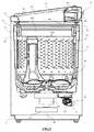
- Figure 2 is a side sectional view showing an internal structure of a full-automatic washing machine 1.
- the full-automatic washing machine 1 has a housing 10 forming the appearance.
- the housing 10 includes: a square tubular machine body part 11 of which an upper and a lower surfaces are opened; an upper panel 12 covering the upper surface of the machine body part 11; and a footstool 13 which supports the machine body part 11.
- a throwing port 14 of washings is formed on the upper panel 12.
- the throwing port 14 is covered by an upper cover 15 which can be freely opened and closed.
- an outer tank 20 is elastically supported upwardly by four hanging rods 21 having anti-vibration devices.
- a washing and dewatering tank 22 is configured in the outer tank 20.
- a plurality of dewatering holes 22a are formed in a circumference surface and a balance ring 23 is arranged on an upper part of the washing and dewatering tank 22. Because an inner surface of the balance ring 23 is more convex inwards than an inner surface of the washing and dewatering tank 22, an inner side of the balance ring 23 forms an opening part 22b of the upper surface of the washing and dewatering tank 22.
- An impeller 24 is configured at a bottom of the outer tank 20.
- a drive unit 30 configured to drive the washing and dewatering tank 22 and the impeller 24 is configured on an outer bottom of the outer tank 20.
- the drive unit 30 includes a drive motor 31 and a transfer mechanism 32.
- the transfer mechanism 32 has a clutch mechanism. Through switching operations performed by the clutch mechanism, in a washing process and a rinsing process, a drive force of the drive motor 31 is only transferred to the impeller 24 so as to only make the impeller 24 rotate. In a dewatering process, a drive force of the drive motor 31 is transferred to the impeller 24 and the washing and dewatering tank 22 so as to make the impeller 24 and the washing and dewatering tank 22 rotate integrally.
- the transfer mechanism 32 has a speed reducing mechanism. In a washing process and a rinsing process, the impeller 24 rotates with a reduced speed of a rotational speed of the drive motor 31 in accordance with a deceleration ratio of the speed reducing mechanism.
- a drain unit 40 configured to drain water from the washing and dewatering tank 22 and the outer tank 20 is also configured.
- the drain unit 40 has a drain pipe 41 and a drain valve 42 and is connected with a drain hose not shown. When the drain valve 42 is opened, water accumulated in the washing and dewatering tank 22 and the outer tank 20 is drained from the washing machine through the drain pipe 41 and the drain hose.
- a water supply unit 50 for supplying running water into the washing and dewatering tank 22 is configured at a back part of the upper panel 12.
- the water supply unit 50 includes a water supply valve 51 connected with a water tap. When the water supply valve 51 is opened, the running water is guided into the water supply unit 50 and flows from a water filling port 52 of the water supply unit 50 into the washing and dewatering tank 22.
- Figure 3 is a top view showing a full-automatic washing machine 1 on which an upper cover 15 is opened.
- Figure 4 is an enlarged view showing a main part of an upper panel 12 of a structure of a body operating part 60.
- the throwing port 14 forms a shape of a circle besides a straight-line-shaped part on back of the throwing port 14.
- An inner diameter of the throwing port 14 is made to be larger than an inner diameter of the opening part 22b of the washing and dewatering tank 22. That is, an opening of the throwing port 14 is larger than the opening part 22b besides a part of the back of the throwing port 14.
- a body operating part 60 is arranged on a right front corner of the upper panel 12. As shown in Figure 4 , the body operating part 60 includes a power key 61, a starting key 62, and a body display part DP which is composed of a remaining time display part 63, a door lock display part 64 and a mode display part 65.
- the power key 61 is a key for switching on and switching off a power supply of a body of the full-automatic washing machine 1.
- the starting key 62 is a key for starting a washing operation.
- the remaining time display part 63 includes three seven-segment display LEDs, and the seven-segment display LEDs display remaining time of the washing operation.
- the door lock display part 64 includes LEDs which are illuminated when the upper cover 15 is in a locked state.
- the mode display part 65 includes annular phototubes which can emit light and have a plurality of colors, and the phototubes are illuminated in a color corresponding to an operating mode.
- Figure 5 is a block diagram showing a structure of the full-automatic washing machine 1.
- the body operating part 60 further includes a first control part 66, a first storing part 67 and a receiving part 68 besides the power key 61, the starting key 62, the remaining time display part 63, the door lock display part 64 and the mode display part 65.
- the water supply unit 50 includes a bathwater water pump 53.
- the bathwater water pump 53 is connected with a bathwater hose not shown in figures. Under a state that a water absorbing port part of the bathwater hose is put into a bathtub accumulated with remaining hot water, when the bathwater water pump 53 is operated, the bathwater is pumped up and the pumped bathwater is supplied into the washing and dewatering tank 22 from the water filling port 52 of the water supply unit 50.
- the full-automatic washing machine 1 is provided with a water level sensor 71 for detecting a water level in the washing and dewatering tank 22; a door lock device 72 for locking the closed upper cover 15; and a buzzer 73 for outputting ending sounds indicating an end of a washing operation, and anomaly notifying sounds indicating generation of anomaly, etc.
- the first storing part 67 includes EEPROM, RAM, etc.
- the first storing part 67 has: an operating program storing part 67a, an operating condition storing part 67b, a temporary storing part 67c and a process mark 67d.
- the operating program storing part 67a, the operating condition storing part 67b and the process mark 67d are arranged on the EEPROM, and the temporary storing part 67c is arranged on the RAM.
- the operating program storing part 67a stores operating programs of various operating processes of a standard process, a self-shunting process, a quick washing process, a drying process, a blanket process and a tank washing process which can be executed by the full-automatic washing machine 1.
- the standard process is an operating program for ordinary washing.
- the self-shunting process is an operating process for a washing operation under various operating conditions set by a user, where a set value is stored, and identical operating conditions are also used in a washing operation of a next self-shunting process.
- the quick washing process is an operating process used in quick washing.
- the drying process is an operating process for washing diaphanous clothes.
- the blanket process is an operating process for washing blankets.
- the tank washing process is an operating process for washing the washing and dewatering tank 22.
- the operating condition storing part 67b stores various operating conditions of a water level, washing time, number of rinsing times and dewatering time in a unit of each operating process.
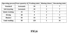
- Figure 6 shows one example indicating operating conditions stored in the operating condition storing part 67b.
- Various operating conditions are set as standard values in the standard process. In the self-shunting process, various operating conditions as initial values are set as same values as those in the standard process, and various operating conditions are updated as new values when newly set by the user. In the quick washing process, various operating conditions are set in a mode that each operating time becomes short. Various operating conditions are set as values suitable for washing diaphanous clothes in the drying process. Various operating conditions are set as values suitable for washing blankets in the blanket process.
- Various operating conditions are set as values suitable for washing the washing and dewatering tank 22 in the tank washing process.
- a known load amount detecting method is used for detecting a load amount of washings in the washing and dewatering tank 22, and the water level is determined according to the detected load amount.
- the temporary storing part 67c stores operating processes set as operating processes which should be executed, as well as operating conditions related to operating programs.
- the process mark 67d is a mark for keeping an operating process executed finally.
- the process mark 67d has bits corresponding to various operating processes, and a bit of an operating process executed finally is created from the bits.
- the first storing part 67 further stores a program for executing an aftermentioned main control processing of the full-automatic washing machine 1.
- the first control part 66 controls various loads of the remaining time display part 63, the door lock display part 64, the mode display part 65, the drive motor 31, the water supply valve 51, the bathwater water pump 53, the drain valve 42, the door lock device 72, the buzzer 73 and the like according to programs stored in the first storing part 67 based on various signals from the power key 61, the starting key 62, the receiving part 68, water level sensor 71, etc.
- the receiving part 68 receives wireless signals transmitted from an aftermentioned remote controller 100, converts the received wireless signals into operating information (operating processes and operating conditions) and outputs the operating information to the first control part 66.
- the full-automatic washing machine 1 performs a washing operation of operating processes selected from a plurality of above operating processes by the user.
- the washing operation includes a washing process, an intermediate dewatering process, a rinsing process and a final dewatering process.
- the impeller 24 rotates in a left direction and a right direction.
- a water flow is generated in the washing and dewatering tank 22 through rotation of the impeller 24.
- washings are washed through the generated water flow and detergents contained in water.
- washings are rinsed through the generated water flow.
- the washing and dewatering tank 22 and the impeller 24 rotate integrally at a high speed. Washings are dewatered through a centrifugal effect generated in the washing and dewatering tank 22.
- the full-automatic washing machine 1 has a remote controller 100 as a setting operating part.
- Figures 7(a), (b) and (c) respectively indicate a main view, a right view and a back view of a structure of the remote controller 100.
- the remote controller 100 includes a housing 110; a setting key group 120, a transmitting key 130 and an information display part 140 arranged on a front surface of the housing 110; and a confirming key 150 arranged on a right side surface of the housing 110.
- the housing 110 is composed of an upper housing 111 and a lower housing 112.
- a gasket 113 is inserted between the upper housing 111 and the lower housing 112, so as to prevent water from entering the housing 110.
- a magnet 114 is arranged on a back surface of the housing 110.
- the machine body part 11 of the housing 10 of the full-automatic washing machine 1 is formed by a steel plate as a magnetic body.
- the remote controller 100 can be detachably installed on a side surface and a front surface of the housing 10.
- the magnetic force of the magnet 114 is preferably of a strength which may not cause separation of the remote controller 100 due to vibration of the housing 10 during dewatering.
- the setting key group 120 is composed of various setting keys for setting various operating information, i.e., a process key 121 for setting operating processes, a water quantity key 122 for setting water quantity, a washing key 123 for setting washing time, a rinsing key 124 for setting number of rinsing times, a dewatering key 125 for setting dewatering time, a drying key 126 for setting drying time of air drying, a reserving key 127 for setting reserving time, and a bathwater key 128 for setting existence of water supply of bathwater.
- a process key 121 for setting operating processes
- a water quantity key 122 for setting water quantity
- a washing key 123 for setting washing time
- a rinsing key 124 for setting number of rinsing times
- a dewatering key 125 for setting dewatering time
- a drying key 126 for setting drying time of air drying
- a reserving key 127 for setting reserving time
- the transmitting key 130 is a key for transmitting set operating information.
- the confirming key 150 is a key for confirming details of an operating process during setting or an operating process which is set finally.
- the information display part 140 is, for example, a liquid crystal display.
- the information display part 140 displays operating information set by the setting key group 120.
- the information display part 140 displays details of the operating processes based on pressing down of the confirming key 150.
- the information display part 140 represents all displayed information for convenience.
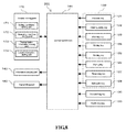
- Figure 8 is a block diagram showing a structure of the remote controller 100.
- a second control part 160, a second storing part 170 and a transmitting part 180 are configured in the housing 110.
- the second storing part 170 includes EEPROM, RAM, etc.
- the second storing part 170 has a setting candidate storing part 171, an operating condition storing part 172, a transmission information storing part 173 and a latest information storing part 174.
- the setting candidate storing part 171, the operating condition storing part 172 and the latest information storing part 174 are arranged on the EEPROM, and the transmission information storing part 173 is arranged on the RAM.
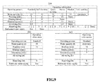
- Figures 9(a) to 9(c) are diagrams showing one example of operating information stored in the setting candidate storing part 171, the transmission information storing part 173 and the latest information storing part 174.
- the setting candidate storing part 171 stores operating information forming setting candidates during setting based on the setting key group 120.
- the operating condition storing part 172 is as same as the operating condition storing part 67b of the body operating part 60, and stores various operating conditions of a water level, washing time, number of rinsing times and dewatering time in a unit of each operating process (referring to Figure 6 ).
- the transmission information storing part 173 stores various operating information set by the setting key group 120.
- An example of the transmission information storing part 173 for storing operating information related to operating processes, water quantity, the washing time, the reserving time and a bathwater water supply is shown in Figure 9(b) .
- the latest information storing part 174 stores operating information finally transmitted to the body operating part 60.
- An example of the latest information storing part 174 for storing operating information related to the standard process in which the reserving time and the bathwater water supply are added is shown in Figure 9(c) .
- the transmitting part 180 converts the operating information set by the setting key group 120 and stored in the transmission information storing part 173 into wireless signals, and transmits the converted wireless signals to the receiving part 68 of the body operating part 60.
- the wireless signals may also be any wireless signal such as infrared rays, electric waves, etc.
- the user presses the power key 61 to energize the body of the full-automatic washing machine 1.
- the body of the full-automatic washing machine 1 is subjected to a main control processing by the first control part 66.
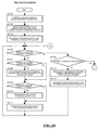
- Figure 10 and Figure 11 are flow charts showing the main control processing.
- Figures 12(a) to 12(c) are diagrams showing a condition of illuminating the display part 65 according to an operating mode.
- the first control part 66 confirms a previous operating process (S101) by referring to the process mark 67d.
- the first control part 66 reads an operating program of the previous operating process from the storing part 67a, and reads operating conditions related to the previous operating process from the operating condition storing part 67b, so that the read operating program and operating conditions are stored in the temporary storing part 67c (S102).
- the first control part 66 illuminates the mode display part 65 in a color such as orange indicating that an operating mode is in a state of a process continuing mode of continuing the previous operating process (S103).
- the first control part 66 judges whether the operating information is received from the remote controller 100, whether a long pressing operation is performed on the starting key 62 and whether a starting operation is performed on the starting key 62 (S104, S105 and S106). The first control part 66 judges that the long pressing operation is performed under a condition that the starting key 62 is continuously pressed over certain time (e.g., 6 seconds), and judges that the starting operation is performed under a condition that the starting key 62 is continuously pressed less than the certain time.
- certain time e.g. 6 seconds
- the user uses the remote controller 100 to set operating information (operating processes and operating conditions), and transmits the set operating information.
- a setting method based on the operating information of the remote controller 100 is described in detail below.
- the first control part 66 judges whether a change of an operating process exists (S107). Under a condition that the received operating information includes an operating program different from the previous operating process, the first control part 66 judges that the change of the operating process exists. Under a condition that the change of the operating process exists (S107: Yes), the first control part 66 reads an operating program of a new operating process from the operating program storing part 67a, and reads operating conditions related to the new operating process from the operating condition storing part 67b, and stores the read operating program and operating conditions in the temporary storing part 67c (S108). In this way, the new operating process is set as an operating process which should be executed.
- the first control part 66 judges whether a change of operating conditions exists (S109). Under a condition that the received operating information includes operating conditions different from operating conditions stored in the temporary storing part 67c, the first control part 66 judges that the change of operating conditions exists. In addition, under a condition that the change of the operating process exists, during the judgment, operating conditions stored in the temporary storing part 67c are operating conditions of the new operating process, and are operating conditions of the previous operating process as long as there is no change of the operating process. Under a condition that the change of operating conditions exists (S109: Yes), the first control part 66 updates operating conditions in the temporary storing part 67c (S110).
- the first control part 66 illuminates the mode display part 65 in a color such as blue indicating that an operating mode is in a state of a reception ending mode of ending reception of the operating information from the remote controller 100 (S111).
- a condition that the remote controller 100 is taken to a place away from an installing place of the body of the full-automatic washing machine 1 by the user is considered. In this way, a condition that the remote controller 100 is not on a hand of the user during a washing operation may also happen.
- the starting key 62 of the body operating part 60 can also be used for changing the operating process into the standard process.
- the user Under a condition that the operating process is changed into the standard process, the user performs a long pressing operation on the starting key 62.
- the first control part 66 reads an operating program of the standard process from the operating program storing part 67a, and reads operating conditions related to the standard process from the operating condition storing part 67b, so that the read operating program and operating conditions are stored in the temporary storing part 67c (S112).
- the standard process is set as an operating process which should be executed.
- the first control part 66 illuminates the mode display part 65 in a color such as red indicating that an operating mode is in a state of a standard process setting mode of the standard process set to be based on the long pressing operation (S 113).
- the user When the operating process and operating conditions are not changed or are changed into expected operating process and operating conditions, the user performs a starting operation on the starting key 62.
- the mode display part 65 is extinguished (S114). Then the first control part 66 executes a washing operation according to the operating programs and operating conditions stored in the temporary storing part 67c (S 115).
- a washing process, a rinsing process and a dewatering process are performed with the set water quantity, washing time, number of rinsing times and dewatering time.
- drying time of air drying is set by the remote controller 100, an air drying process is added after a final dewatering process.
- the washing and dewatering tank 22 In the air drying process, the washing and dewatering tank 22 generates a centrifugal force through a high-speed rotation, introduces wind from a ventilation port (not shown in figures) arranged on an upper cover 15 into the washing and dewatering tank 22, and dries washings through effects of the centrifugal force and the wind. Then under a condition that reserving time is set by the remote controller 100, a washing operation is started in a mode of ending the washing operation within the reserving time. Then under a condition that a bathwater water supply is set by the remote controller 100, the running water is replaced by bathwater which is supplied into the washing and dewatering tank 22 in the washing process.
- washing time number of rinsing times and the dewatering time
- a process which is set as “none” is not performed.
- the drying time of air drying, the reserving time and the bathwater water supply are set, when a "none" setting is made regarding above conditions, the setting is released.
- the first control part 66 updates the process mark 67d in a mode of keeping a new operating process (S117). Then under a condition that an executed operating process is a self-shunting process and operating conditions are changed (S118: Yes-> S119: Yes), the first control part 66 updates operating conditions of the self-shunting process stored in the operating condition storing part 67b (S120). Then the first control part 66 deenergizes the body of the full-automatic washing machine 1 (S121), and ends the main control processing.
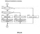
- a second control part 160 executes a setting and transmission processing for setting operating information and transmitting the operating information to the body operating part 60.
- Figure 13 and Figure 14 are flow charts showing a setting and transmission processing.
- Figures 15(a) to 15(i) are diagrams showing a condition of set operating information displayed by the information display part 140.
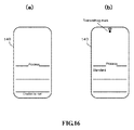
- Figure 16(a) is a diagram showing an information display part 140 displaying information which indicates that operating conditions cannot be set.
- Figure 16(b) is a diagram showing the information display part 140 displaying a transmitting mark.
- the second control part 160 monitors whether any setting key of the setting key group 120 is pressed down (S201). When any setting key is pressed down (S201: Yes), the second control part 160 judges whether the setting key being pressed down is a process key 121 (S202).
- the process key 121 Under a condition that the user sets an operating process, the process key 121 is pressed down. Under a condition that the process key 121 is already pressed down (S202: Yes), as long as the pressing down of the process key 121 is a first pressing down (S203: Yes), the second control part 160 judges whether operating conditions are stored in the transmission information storing part 173 before the pressing down of the process key 121 (S204).
- the second control part 160 deletes stored operating conditions (S205). Then the second control part 160 displays a first operating process in a predetermined display sequence on the information display part 140 (S206). For example, under a condition of a standard process, as shown in Figure 13(a) , a display region of operating processes in the information display part 140 displays a word "standard”. Then the second control part 160 stores the first operating process in the transmission information storing part 173 (S207).
- the process key 121 Under a condition that an operating process displayed earliest is not an expected operating process, the process key 121 is pressed down again by the user. Under a condition that the pressing down of the process key 121 is not the first pressing down (S203: No), the second control part 160 displays a next operating process in the display sequence on the information display part 140 (S208). As shown in Figure 15(a) , when the process key 121 is pressed down each time, a display of operating processes in the information display part 140 is switched in accordance with the display sequence. Then the second control part 160 replaces a next operating process by a previously stored operating process and stores the next operating process in the transmission information storing part 173 (S209). In this way, the transmission information storing part 173 stores an operating process finally selected by the user.
- the second control part 160 judges whether setting of operating conditions can be performed through the setting key being pressed down (S210).
- the self-shunting process and the quick washing process setting of all operating conditions of water quantity, washing time, number of rinsing times, dewatering time, drying time of air drying, reserving time and bathwater water supply can be performed.
- the drying process and the blanket process although the water quantity, washing time, number of rinsing times, dewatering time and drying time of air drying cannot be set, an existence of the reserving time and bathwater water supply can be set.
- any operating condition cannot be set.
- the second control part 160 judges whether a setting can be performed according to operating processes stored in the transmission information storing part 173. On the other hand, under a condition that no operating process is set, the second control part 160 judges whether a setting can be performed according to operating processes stored in the latest information storing part 174.
- the second control part 160 displays a first operating condition corresponding to the setting key being pressed down in the predetermined display sequence on the information display part 140 (S212) and stores the first operating condition in the transmission information storing part 173 (S213).
- the second control part 160 displays a next operating condition corresponding to the setting key being pressed down in the display sequence on the information display part 140 (S214) and stores the next operating condition in the transmission information storing part 173 (S215).
- An operating condition finally selected by the user is stored in the transmission information storing part 173.
- the information display part 140 displays initial water quantity, e.g., "15 liters", and then switches display of water quantity when the water quantity key 122 is pressed down each time.
- the information display part 140 displays initial washing time, e.g., "5 minutes”, and then switches display of the washing time when the washing key 123 is pressed down each time.
- the information display part 140 displays number of initial rinsing times, e.g., "1 time”, and then switches display of number of rinsing times when the rinsing key 124 is pressed down each time.
- the information display part 140 displays initial dewatering time, e.g., "0.5 minute”, and then switches display of the dewatering time when the dewatering key 125 is pressed down each time.
- the information display part 140 displays initial drying time, e.g., "0.5 hour”, and then switches display of the drying time when the drying key 126 is pressed down each time.
- the information display part 140 displays initial reserving time, e.g., "1 hour”, and then switches display of the reserving time when the reserving key 127 is pressed down each time.
- a lower display region of the information display part 140 displays a word "bathwater” indicating that a bathwater water supply is set, and next, when the bathwater key 128 is pressed down, the word "bathwater” is deleted.
- the information display part 140 displays a transverse color bar ("-").
- the information display part 140 displays words indicating various operating conditions of "washing", “rinsing” and the like according to pressing down of each setting key based on values of various operating conditions.
- a reserving condition is shown in Figure 15(g)
- the lower display region of the information display part 140 also displays a word "reserving" which indicates existence of a reserving setting. Then, under a condition that an operating process is firstly set prior to setting of operating conditions, as shown in Figure 15(i) , the display region of operating processes of the information display part 140 displays the operating process.
- step S210 under a condition that the second control part 160 judges that operating conditions cannot be set through the setting key being pressed down (S210: No), as shown in Figure 16(a) , information indicating that operating conditions cannot be set is displayed on the information display part 140 (S216).
- the second control part 160 monitors whether the setting key is pressed down, and monitors whether the transmitting key 130 is pressed down (S217).
- the transmitting key 130 is pressed down by the user.
- the second control part 160 judges whether the operating process includes operating information stored in the transmission information storing part 173 (S218). As long as the operating process does not include the operating information (S218: No), the second control part 160 reads an operating process from the latest information storing part 174 and adds the read operating process to the transmitted operating information (S219). Thus, the read operating process is stored in the transmission information storing part 173.
- the second control part 160 outputs operating information in the transmission information storing part 173 to the transmitting part 180, and transmits the operating information to the transmitting part 180 (S220).
- the second control part 160 displays a transmitting mark on the information display part 140 (S221).
- the remote controller 100 Under a condition that an operating process is not set and only operating conditions of washing time and the like are set, on a premise of an operating process transmitted finally, operating conditions related to the operating process are set.
- the body operating part 60 sometimes sets a standard process through a long pressing operation of the starting key 62.
- an operating process stored in the remote controller 100 is inconsistent with an operating process stored in the body operating part 60.
- there is a possibility that some transmitted operating conditions are suitable for a standard process different from an operating process stored in the remote controller 100 so that a washing operation expected by the user cannot be performed.
- the body operating part 60 changes the operating process to be consistent with the operating process on a remote controller 100 side since the operating process stored in the remote controller 100 is transmitted. Thus, a washing operation expected by the user can be performed.
- the second control part 160 updates operating information in the latest information storing part 174 according to the transmitted operating information (S222).
- the remote controller 100 stores an operating process executed currently in the full-automatic washing machine 1 and operating conditions related to the operating programs of the operating process.
- the transmitted operating information is an operating condition related to a self-shunting process (S223: Yes)
- the second control part 160 updates operating conditions related to the self-shunting process in the operating condition storing part 172 according to the transmitted operating information (S224).
- the second control part 160 deletes operating information in the transmission information storing part 173 (S225). Then the second control part 160 extinguishes the information display part 140 (S226), and ends setting of the transmission processing.
- the second control part 160 extinguishes the information display part 140 and ends setting of the transmission processing after an operation of any key of the setting key group 120 is performed once and when a state of not generating a key operation lasts for certain time.
- the user can set operating information of operating processes, operating conditions and the like in the remote controller 100, and transmit the set operating information to the body operating part 60 of the body of the full-automatic washing machine 1 through unidirectional wireless communication.
- the user can confirm details of an operating process which is being set or finally set by the remote controller 100 according to an operation of the confirming key 150.
- An operating information display processing for displaying details of an operating process on the information display part 140 is executed by the second control part 160.
- Figure 17 is a flow chart showing an operating information display processing.
- Figure 18 is a diagram showing an example of a display form in case of displaying details of operating processes on the information display part 140.
- the second control part 160 monitors whether the confirming key 150 is pressed down (S301). When the confirming key 150 is pressed down (S301: Yes), the second control part 160 judges whether operating information is being set (S302). As long as the operating information is not being set (S302: No), the second control part 160 reads operating information from the latest information storing part 174 (S303). On the other hand, under a condition that the operating information is being set (S302: Yes), the second control part 160 reads the operating information which has been already set from the transmission information storing part 173 (S304), and reads operating information other than the operating information which has been already set from the latest information storing part 174 (S305).
- the second control part 160 displays the read operating information, i.e., operating processes and operating conditions, on the information display part 140 (S306).
- the information display part 140 displays an operating process.
- the information display part 140 displays water quantity, washing time, number of rinsing times and dewatering time related to the operating process in order, and displays drying time and reserving time in order under a condition that settings of air drying and reserving exist. Then under a condition that setting of reserving and setting of a bathwater water supply exist, the information display part 140 displays words "reserving" and "bathwater” indicating settings of reserving and bathwater water supply.
- the information display part 140 displays a word "confirming" which indicates that a mode of the remote controller 100 is in a state of a mode of details of operating processes.
- display of water quantity, washing time, number of rinsing times, dewatering time, drying time and reserving time can be switched when the confirming key 150 is pressed down each time, and can also be switched after certain time each time.
- a communication mode as wireless communication between the remote controller 100 and the body operating part 60 uses a unidirectional communication mode, a simple structure can be made into a structure for communication. In addition, cost and power consumption can be reduced.
- the mode display part 65 is illuminated in a color corresponding to reception of the operating information until a washing operation starts.
- the user can also confirm that the receiving part 68 has received the operating information when an operation of starting the washing operation is performed.
- a washing operation can be started by the user on the basis of performing resetting of operating information.
- a washing operation unexpected by the user can be prevented.
- the user can set the standard process with a highest use frequency in the body of the full-automatic washing machine 1. Therefore, use convenience of the user can be optimized.
- the mode display part 65 is illuminated in a color corresponding to the standard process. Thus, the user can confirm that the long pressing operation is accepted and the operating process is set as the standard process.
- the user can confirm details of an operating process which is being set or finally set in the remote controller 100 by operating the confirming key 150.
- the remote controller 100 is provided with a magnet 114, and the machine body part 11 of the housing 10 is formed by a magnetic body. Therefore, the user can easily install the remote controller 100 on the body of the full-automatic washing machine 1.
- washings can be easily thrown into and withdrawn from the washing and dewatering tank 22 by the user from the front of the full-automatic washing machine 1.
- the body display part DP is arranged on the corner having a large space in the upper panel 12, the body display part DP can be expanded.
- the mode display part 65 by enabling the mode display part 65 to have different colors, a notification of various operating modes of a process continuing mode, a reception ending mode and a standard process setting mode is performed.
- the mode display part 65 may also not be arranged in the body operating part 60, and corresponding operating modes are displayed in color bars with different colors on the remaining time display part 63.
- positions of the seven-segment display LEDs illuminated corresponding to operating modes can also be changed. That is, display modes corresponding to various operating modes can be any mode. Under a condition of a structure of Figure 19(b) , then in positions below each seven-segment display LED on a right front corner of the upper panel 12, names and abbreviations of each corresponding operating mode can also be printed.
- a structure of not illuminating the mode display part 65 and the remaining time display part 63 can also be adopted when an operating mode is the process continuing mode, i.e., before it is changed into the reception ending mode or the standard process setting mode.
- display which indicates the reception ending mode i.e., display corresponding to the reception of the operating information
- display corresponding to the reception of the operating information can also be ended at a moment after certain time from the start of the washing operation or at a moment after an end of the washing operation.
- display corresponding to the reception of the operating information can also be timed after certain time from the reception of the operating information, and is ended after certain time.
- display corresponding to the reception of the operating information is ended prior to the start of the washing operation after certain time before the starting key 62 is pressed, and can be ended at a moment under a condition that the starting key 62 is pressed prior to certain time, and can also be displayed continually until certain time passes.
- the standard process is set through the long pressing operation of the starting key 62
- the standard process can also be set through other operations different from the starting operation; for example, within determined time, the standard process is set through an operation that the starting key 62 is only pressed for number of more than two determined times.
- the starting key 62 is arranged on the body operating part 60
- the starting key 62 can also be arranged on the remote controller 100, i.e., the setting operating part.
- the setting of the standard process based on the long pressing operation of the starting key 62 is not performed, and processing of steps S105, S112 and S113 are deleted from the main control processing shown in Figure 10 .
- the setting operating part is formed by the remote controller 100.
- the setting operating part is only required to be separated from the body display part DP of the first display part, and can also be arranged on other members different from the upper panel 12, e.g., a front of the machine body part 11, etc.
- the first control part 66, the first storing part 67 and the receiving part 68 are included in the body operating part 60 of the upper panel 12.
- the first control part 66, the first storing part 67 and the receiving part 68 may not necessarily be included in the body operating part 60.
- the first control part 66, the first storing part 67 and the receiving part 68 can also be arranged on positions other than the upper panel 12 of the body of the full-automatic washing machine 1.
- the full-automatic washing machine 1 of above embodiments has no drying function performed through a heater
- the present disclosure is also suitable for the full-automatic washing machine having the drying function performed through the heater. Then, the present disclosure is suitable for a drum type washing machine.
Landscapes
- Engineering & Computer Science (AREA)
- Computer Networks & Wireless Communication (AREA)
- Textile Engineering (AREA)
- Control Of Washing Machine And Dryer (AREA)
- Detail Structures Of Washing Machines And Dryers (AREA)
Abstract
Description
- The present disclosure relates to a washing machine.
- In the past, a throwing port is formed on an upper surface of a housing of a washing machine, and an operating part is arranged to be adjacent to the throwing port. In the operating part, besides a power key and a starting key, a plurality of setting keys for setting operating information involving a washing operation, an information display part for displaying the set operating information, and the like are configured. Operating information involving the washing operation includes operating processes of a standard process, a self-shunting process, a quick washing process and the like, as well as operating conditions of washing time, number of rinsing times, dewatering time, etc.
- As stated above, because the operating part has a plurality of keys and an information display part, a large region is occupied at the upper surface of the housing. Therefore, in an existing washing machine, it is difficult to arrange a throwing port large enough for an opening part of a washing tank.
- Therefore, to diminish the operating part, in the washing machine, a structure can be adopted in such a manner that the setting keys and the information display part are at least configured on a remote controller separated from the operating part, and the remote controller transmits operating information to the operating part in a wireless mode (referring to patent document 1).
- Patent document 1:
JP Laid-Open 2009-226060 - As a communication mode performed in a wireless mode, a bidirectional communication mode and a unidirectional communication mode can be adopted. Under a condition of adopting the unidirectional communication mode, a structure for communication can be made into a simple structure. In addition, cost and power consumption can be reduced.
- However, under a condition of adopting the unidirectional communication mode, transmission from an operating part of a body side to the remote controller is not performed. Therefore, when a user transmits operating information from the remote controller, the transmitted operating information is received by the operating part, so that, based on this, it is impossible to confirm on a remote controller side whether the operating part has performed update of operating information. Therefore, under a condition of not receiving a wireless signal, and when the transmitted operating information is not received by the operating part for a certain reason and a washing operation is started directly with previous operating information, a hidden danger that washing cannot be performed according to an intention of the user may exist.
- The present disclosure is accomplished in view of such a problem and aims to provide a washing machine. Under a condition that the washing machine is constituted in a mode of setting operating information involved in a washing operation of operating processes, operating conditions and the like in a unidirectional wireless communication mode, a condition that a washing operation cannot be performed according to an intention of the user due to incomplete reception of the operating information can be prevented.
- The washing machine involved in a main embodiment of the present disclosure includes: a washing tank for performing washing of washings; a housing for accommodating the washing tank; a first display part arranged on a surface having a throwing port of the housing; a first control part; a receiving part; and a setting operating part separated from the first display part. Here, the setting operating part includes: setting keys for setting operating information involved in a washing operation; a second control part; a second display part; and a transmitting part. The second control part displays the operating information set by the setting keys through the second display part, and transmits the operating information by the transmitting part to the receiving part through wireless communication. The first control part executes a washing operation based on the operating information received by the receiving part, and the first display part is illuminated in a first form corresponding to the reception of the operating information at least within a specified period until washing the operation starts when the operating information is received by the receiving part.
- According to the above structure, when the operating information set by the setting operating part is received by the receiving part, the first display part is illuminated in a first form corresponding to the reception of the operating information, e.g., a color corresponding to the reception at least within a specified period until the washing operation starts. Thus, the user can confirm that the receiving part has received the set operating information, and when the operating information is not received, the washing operation can be started on the basis of performing resetting of the operating information. Therefore, a washing operation not in accordance with an intention of the user can be prevented from being performed.
- The washing machine of the present embodiment can adopt a structure in which a starting key for starting the washing operation is arranged on a surface having the throwing port. In addition, the operating information can include a plurality of operating processes having a standard process. In this case, when the first control part performs a specified operation on the starting key different from start of the washing operation, the standard process is set as an operating process which should be executed by replacing an operating process received by the receiving part prior to the operation.
- According to the above structure, because not only the setting operating part, but also the starting key is configured to set with respect to the standard process with a highest use frequency, use convenience of the user can be optimized.
- Under a condition of adopting the above structure, then, the first control part can adopt a structure that when the standard process is set as the operating process which should be executed based on the specified operation, the first display part is illuminated in a second form different from the first form.
- As long as such structure is adopted, the user can confirm that the specified operation is accepted and operating processes are set in the standard process.
- Then, in the washing machine of the present embodiment, the setting operating part can adopt a structure having a confirming key and an operating information storing part for storing the operating information. In this case, the second control part can adopt a structure that the operating information transmitted by the transmitting part is stored in the operating information storing part, and the operating information stored in the operating information storing part is read and the read operating information is displayed by the second display part when the confirming key is operated.
- According to the above structure, the user can confirm that the operating information is set by the setting operating part by operating the confirming key.
- Then, in the washing machine of the present embodiment, the setting operating part can adopt a remote controller. In this case, then, the washing machine of the present embodiment can adopt a structure that a magnet is arranged in the remote controller and a magnetic body forms at least a part of the housing.
- According to the above structure, the user can easily install the remote controller in a body of the washing machine.
- Then, the washing machine of the present embodiment can adopt a structure that the washing tank has an opening part on an upper surface, the throwing port is formed on the upper surface of the housing, at least a front opening of the throwing port is larger than the opening part, and the first display part is arranged on a corner of a front side on the upper surface of the housing.
- According to the above structure, because at least a front of the throwing port is larger than the opening part of the washing tank, washings can be easily thrown into and withdrawn from the washing tank by the user from the front of the washing machine. Then, because the first display part is arranged on the corner having a large space on the upper surface of the housing, the first display part can be expanded.
- According to the present disclosure, under a condition that the washing machine adopts a structure of setting the operating information involved in a washing operation through unidirectional wireless communication, a condition that a washing operation not in accordance with an intention of the user due to incomplete reception of the operating information can be prevented from being performed.
- Effects or significance of the present disclosure is further defined according to description of embodiments shown below. However, the embodiments below are only examples when the present disclosure is implemented, and the present disclosure is not limited by any of the embodiments below.
-
-
Figure 1 is a main view showing an appearance of a full-automatic washing machine involved in embodiments; -
Figure 2 is a side sectional view showing an internal structure of a full-automatic washing machine involved in embodiments; -
Figure 3 is a top view showing a full-automatic washing machine on which an upper cover is opened involved in embodiments; -
Figure 4 is an enlarged view showing a main part of an upper panel of a structure of a body operating part involved in embodiments; -
Figure 5 is a block diagram showing a structure of a full-automatic washing machine involved in embodiments; -
Figure 6 is a diagram showing one example of operating conditions stored in an operating condition storing part involved in embodiments; -
Figure 7 a diagram showing a main view, a right view and a back view of a structure of a remote controller involved in embodiments; -
Figure 8 is a block diagram showing a structure of a remote controller involved in embodiments; -
Figure 9 is a diagram showing one example of operating information stored in a setting candidate storing part, a transmission information storing part and a latest information storing part involved in embodiments; -
Figure 10 is a flow chart showing a main control processing involved in embodiments; -
Figure 11 is a flow chart showing a main control processing involved in embodiments; -
Figure 12 is a diagram showing a condition of illuminating a mode display part according to an operating mode involved in embodiments; -
Figure 13 is a flow chart showing setting of a transmission processing involved in embodiments; -
Figure 14 is a flow chart showing setting of a transmission processing involved in embodiments; -
Figure 15 is a diagram showing a condition of displaying set operating information by the information display part involved in embodiments; -
Figure 16 is a diagram showing an information display part displaying information which indicates that operating conditions cannot be set as well as an information display part displaying a transmitting mark involved in embodiments; -
Figure 17 is a flow chart showing an operating information display processing involved in embodiments; -
Figure 18 is a diagram showing an example of a display form when an information display part displays details of operating processes involved in embodiments; -
Figure 19 is a diagram showing a condition of illuminating a remaining time part according to an operating mode involved in a changed example. - Description is made below to a full-automatic washing machine as one embodiment of a washing machine of the present disclosure with reference to drawings.
-
Figure 1 is a main view showing an appearance of a full-automatic washing machine 1.Figure 2 is a side sectional view showing an internal structure of a full-automatic washing machine 1. - The full-
automatic washing machine 1 has ahousing 10 forming the appearance. Thehousing 10 includes: a square tubularmachine body part 11 of which an upper and a lower surfaces are opened; anupper panel 12 covering the upper surface of themachine body part 11; and afootstool 13 which supports themachine body part 11. A throwingport 14 of washings is formed on theupper panel 12. The throwingport 14 is covered by anupper cover 15 which can be freely opened and closed. - In the
housing 10, anouter tank 20 is elastically supported upwardly by four hangingrods 21 having anti-vibration devices. A washing anddewatering tank 22 is configured in theouter tank 20. In the washing anddewatering tank 22, a plurality ofdewatering holes 22a are formed in a circumference surface and abalance ring 23 is arranged on an upper part of the washing anddewatering tank 22. Because an inner surface of thebalance ring 23 is more convex inwards than an inner surface of the washing anddewatering tank 22, an inner side of thebalance ring 23 forms anopening part 22b of the upper surface of the washing anddewatering tank 22. Animpeller 24 is configured at a bottom of theouter tank 20. - A
drive unit 30 configured to drive the washing anddewatering tank 22 and theimpeller 24 is configured on an outer bottom of theouter tank 20. Thedrive unit 30 includes adrive motor 31 and atransfer mechanism 32. Thetransfer mechanism 32 has a clutch mechanism. Through switching operations performed by the clutch mechanism, in a washing process and a rinsing process, a drive force of thedrive motor 31 is only transferred to theimpeller 24 so as to only make theimpeller 24 rotate. In a dewatering process, a drive force of thedrive motor 31 is transferred to theimpeller 24 and the washing anddewatering tank 22 so as to make theimpeller 24 and the washing anddewatering tank 22 rotate integrally. In addition, thetransfer mechanism 32 has a speed reducing mechanism. In a washing process and a rinsing process, theimpeller 24 rotates with a reduced speed of a rotational speed of thedrive motor 31 in accordance with a deceleration ratio of the speed reducing mechanism. - On the outer bottom of the
outer tank 20, adrain unit 40 configured to drain water from the washing anddewatering tank 22 and theouter tank 20 is also configured. Thedrain unit 40 has adrain pipe 41 and adrain valve 42 and is connected with a drain hose not shown. When thedrain valve 42 is opened, water accumulated in the washing anddewatering tank 22 and theouter tank 20 is drained from the washing machine through thedrain pipe 41 and the drain hose. - A
water supply unit 50 for supplying running water into the washing anddewatering tank 22 is configured at a back part of theupper panel 12. Thewater supply unit 50 includes awater supply valve 51 connected with a water tap. When thewater supply valve 51 is opened, the running water is guided into thewater supply unit 50 and flows from awater filling port 52 of thewater supply unit 50 into the washing anddewatering tank 22. -
Figure 3 is a top view showing a full-automatic washing machine 1 on which anupper cover 15 is opened.Figure 4 is an enlarged view showing a main part of anupper panel 12 of a structure of abody operating part 60. - On the
upper panel 12, the throwingport 14 forms a shape of a circle besides a straight-line-shaped part on back of the throwingport 14. An inner diameter of the throwingport 14 is made to be larger than an inner diameter of theopening part 22b of the washing anddewatering tank 22. That is, an opening of the throwingport 14 is larger than theopening part 22b besides a part of the back of the throwingport 14. - A
body operating part 60 is arranged on a right front corner of theupper panel 12. As shown inFigure 4 , thebody operating part 60 includes apower key 61, a startingkey 62, and a body display part DP which is composed of a remainingtime display part 63, a doorlock display part 64 and amode display part 65. Thepower key 61 is a key for switching on and switching off a power supply of a body of the full-automatic washing machine 1. The startingkey 62 is a key for starting a washing operation. The remainingtime display part 63 includes three seven-segment display LEDs, and the seven-segment display LEDs display remaining time of the washing operation. The doorlock display part 64 includes LEDs which are illuminated when theupper cover 15 is in a locked state. Themode display part 65 includes annular phototubes which can emit light and have a plurality of colors, and the phototubes are illuminated in a color corresponding to an operating mode. -
Figure 5 is a block diagram showing a structure of the full-automatic washing machine 1. - The
body operating part 60 further includes afirst control part 66, a first storingpart 67 and a receivingpart 68 besides thepower key 61, the startingkey 62, the remainingtime display part 63, the doorlock display part 64 and themode display part 65. - In addition, the
water supply unit 50 includes abathwater water pump 53. Thebathwater water pump 53 is connected with a bathwater hose not shown in figures. Under a state that a water absorbing port part of the bathwater hose is put into a bathtub accumulated with remaining hot water, when thebathwater water pump 53 is operated, the bathwater is pumped up and the pumped bathwater is supplied into the washing anddewatering tank 22 from thewater filling port 52 of thewater supply unit 50. - Then, the full-
automatic washing machine 1 is provided with awater level sensor 71 for detecting a water level in the washing anddewatering tank 22; adoor lock device 72 for locking the closedupper cover 15; and abuzzer 73 for outputting ending sounds indicating an end of a washing operation, and anomaly notifying sounds indicating generation of anomaly, etc. - The
first storing part 67 includes EEPROM, RAM, etc. Thefirst storing part 67 has: an operatingprogram storing part 67a, an operatingcondition storing part 67b, atemporary storing part 67c and aprocess mark 67d. The operatingprogram storing part 67a, the operatingcondition storing part 67b and theprocess mark 67d are arranged on the EEPROM, and thetemporary storing part 67c is arranged on the RAM. - The operating
program storing part 67a stores operating programs of various operating processes of a standard process, a self-shunting process, a quick washing process, a drying process, a blanket process and a tank washing process which can be executed by the full-automatic washing machine 1. The standard process is an operating program for ordinary washing. The self-shunting process is an operating process for a washing operation under various operating conditions set by a user, where a set value is stored, and identical operating conditions are also used in a washing operation of a next self-shunting process. The quick washing process is an operating process used in quick washing. The drying process is an operating process for washing diaphanous clothes. The blanket process is an operating process for washing blankets. The tank washing process is an operating process for washing the washing anddewatering tank 22. - The operating
condition storing part 67b stores various operating conditions of a water level, washing time, number of rinsing times and dewatering time in a unit of each operating process.Figure 6 shows one example indicating operating conditions stored in the operatingcondition storing part 67b. Various operating conditions are set as standard values in the standard process. In the self-shunting process, various operating conditions as initial values are set as same values as those in the standard process, and various operating conditions are updated as new values when newly set by the user. In the quick washing process, various operating conditions are set in a mode that each operating time becomes short. Various operating conditions are set as values suitable for washing diaphanous clothes in the drying process. Various operating conditions are set as values suitable for washing blankets in the blanket process. Various operating conditions are set as values suitable for washing the washing anddewatering tank 22 in the tank washing process. In addition, in an initial stage of a washing operation like the standard process and the self-shunting process, under a condition of setting a water level as "automatic", a known load amount detecting method is used for detecting a load amount of washings in the washing anddewatering tank 22, and the water level is determined according to the detected load amount. - The
temporary storing part 67c stores operating processes set as operating processes which should be executed, as well as operating conditions related to operating programs. Theprocess mark 67d is a mark for keeping an operating process executed finally. Theprocess mark 67d has bits corresponding to various operating processes, and a bit of an operating process executed finally is created from the bits. - The
first storing part 67 further stores a program for executing an aftermentioned main control processing of the full-automatic washing machine 1. - The
first control part 66 controls various loads of the remainingtime display part 63, the doorlock display part 64, themode display part 65, thedrive motor 31, thewater supply valve 51, thebathwater water pump 53, thedrain valve 42, thedoor lock device 72, thebuzzer 73 and the like according to programs stored in the first storingpart 67 based on various signals from thepower key 61, the startingkey 62, the receivingpart 68,water level sensor 71, etc. - The receiving
part 68 receives wireless signals transmitted from an aftermentionedremote controller 100, converts the received wireless signals into operating information (operating processes and operating conditions) and outputs the operating information to thefirst control part 66. - The full-
automatic washing machine 1 performs a washing operation of operating processes selected from a plurality of above operating processes by the user. The washing operation includes a washing process, an intermediate dewatering process, a rinsing process and a final dewatering process. - In the washing process and the rinsing process, in a state that water is accumulated in the washing and
dewatering tank 22, theimpeller 24 rotates in a left direction and a right direction. A water flow is generated in the washing anddewatering tank 22 through rotation of theimpeller 24. In the washing process, washings are washed through the generated water flow and detergents contained in water. In the rinsing process, washings are rinsed through the generated water flow. In the intermediate dewatering process and the final dewatering process, the washing anddewatering tank 22 and theimpeller 24 rotate integrally at a high speed. Washings are dewatered through a centrifugal effect generated in the washing anddewatering tank 22. - The full-
automatic washing machine 1 has aremote controller 100 as a setting operating part.Figures 7(a), (b) and (c) respectively indicate a main view, a right view and a back view of a structure of theremote controller 100. - The
remote controller 100 includes ahousing 110; a settingkey group 120, a transmittingkey 130 and aninformation display part 140 arranged on a front surface of thehousing 110; and a confirming key 150 arranged on a right side surface of thehousing 110. - The
housing 110 is composed of anupper housing 111 and alower housing 112. Agasket 113 is inserted between theupper housing 111 and thelower housing 112, so as to prevent water from entering thehousing 110. Amagnet 114 is arranged on a back surface of thehousing 110. Themachine body part 11 of thehousing 10 of the full-automatic washing machine 1 is formed by a steel plate as a magnetic body. Thus, as shown inFigure 3 , through magnetic force of themagnet 114, theremote controller 100 can be detachably installed on a side surface and a front surface of thehousing 10. In addition, the magnetic force of themagnet 114 is preferably of a strength which may not cause separation of theremote controller 100 due to vibration of thehousing 10 during dewatering. - The setting
key group 120 is composed of various setting keys for setting various operating information, i.e., aprocess key 121 for setting operating processes, awater quantity key 122 for setting water quantity, awashing key 123 for setting washing time, a rinsingkey 124 for setting number of rinsing times, adewatering key 125 for setting dewatering time, a dryingkey 126 for setting drying time of air drying, a reservingkey 127 for setting reserving time, and abathwater key 128 for setting existence of water supply of bathwater. - The transmitting
key 130 is a key for transmitting set operating information. The confirmingkey 150 is a key for confirming details of an operating process during setting or an operating process which is set finally. - The
information display part 140 is, for example, a liquid crystal display. Theinformation display part 140 displays operating information set by the settingkey group 120. In addition, theinformation display part 140 displays details of the operating processes based on pressing down of the confirmingkey 150. In addition, inFigure 7(a) , theinformation display part 140 represents all displayed information for convenience. -
Figure 8 is a block diagram showing a structure of theremote controller 100. Asecond control part 160, asecond storing part 170 and a transmittingpart 180 are configured in thehousing 110. - The
second storing part 170 includes EEPROM, RAM, etc. Thesecond storing part 170 has a settingcandidate storing part 171, an operatingcondition storing part 172, a transmissioninformation storing part 173 and a latestinformation storing part 174. The settingcandidate storing part 171, the operatingcondition storing part 172 and the latestinformation storing part 174 are arranged on the EEPROM, and the transmissioninformation storing part 173 is arranged on the RAM. -
Figures 9(a) to 9(c) are diagrams showing one example of operating information stored in the settingcandidate storing part 171, the transmissioninformation storing part 173 and the latestinformation storing part 174. - The setting
candidate storing part 171, as shown inFigure 9(a) , stores operating information forming setting candidates during setting based on the settingkey group 120. The operatingcondition storing part 172 is as same as the operatingcondition storing part 67b of thebody operating part 60, and stores various operating conditions of a water level, washing time, number of rinsing times and dewatering time in a unit of each operating process (referring toFigure 6 ). The transmissioninformation storing part 173 stores various operating information set by the settingkey group 120. An example of the transmissioninformation storing part 173 for storing operating information related to operating processes, water quantity, the washing time, the reserving time and a bathwater water supply is shown inFigure 9(b) . The latestinformation storing part 174 stores operating information finally transmitted to thebody operating part 60. An example of the latestinformation storing part 174 for storing operating information related to the standard process in which the reserving time and the bathwater water supply are added is shown inFigure 9(c) . - The transmitting
part 180 converts the operating information set by the settingkey group 120 and stored in the transmissioninformation storing part 173 into wireless signals, and transmits the converted wireless signals to the receivingpart 68 of thebody operating part 60. The wireless signals may also be any wireless signal such as infrared rays, electric waves, etc. - Under a condition of performing a washing operation, the user presses the
power key 61 to energize the body of the full-automatic washing machine 1. When a power supply is switched on, the body of the full-automatic washing machine 1 is subjected to a main control processing by thefirst control part 66. -
Figure 10 andFigure 11 are flow charts showing the main control processing.Figures 12(a) to 12(c) are diagrams showing a condition of illuminating thedisplay part 65 according to an operating mode. - When the body of the full-
automatic washing machine 1 is energized, thefirst control part 66 confirms a previous operating process (S101) by referring to theprocess mark 67d. Next, thefirst control part 66 reads an operating program of the previous operating process from the storingpart 67a, and reads operating conditions related to the previous operating process from the operatingcondition storing part 67b, so that the read operating program and operating conditions are stored in thetemporary storing part 67c (S102). Then thefirst control part 66, as shown inFigure 12(a) , illuminates themode display part 65 in a color such as orange indicating that an operating mode is in a state of a process continuing mode of continuing the previous operating process (S103). - Next, the
first control part 66 judges whether the operating information is received from theremote controller 100, whether a long pressing operation is performed on the startingkey 62 and whether a starting operation is performed on the starting key 62 (S104, S105 and S106). Thefirst control part 66 judges that the long pressing operation is performed under a condition that the startingkey 62 is continuously pressed over certain time (e.g., 6 seconds), and judges that the starting operation is performed under a condition that the startingkey 62 is continuously pressed less than the certain time. - Under a condition that a washing operation of an operating process different from the previous operating process is performed, or under a condition that an operating process is identical with the previous operating process while a washing operation is performed with changed operating conditions of washing time, number of rinsing times and the like, the user uses the
remote controller 100 to set operating information (operating processes and operating conditions), and transmits the set operating information. A setting method based on the operating information of theremote controller 100 is described in detail below. - Under a condition that an operating information is already received (S104: Yes), the
first control part 66 judges whether a change of an operating process exists (S107). Under a condition that the received operating information includes an operating program different from the previous operating process, thefirst control part 66 judges that the change of the operating process exists. Under a condition that the change of the operating process exists (S107: Yes), thefirst control part 66 reads an operating program of a new operating process from the operatingprogram storing part 67a, and reads operating conditions related to the new operating process from the operatingcondition storing part 67b, and stores the read operating program and operating conditions in thetemporary storing part 67c (S108). In this way, the new operating process is set as an operating process which should be executed. - Next, the
first control part 66 judges whether a change of operating conditions exists (S109). Under a condition that the received operating information includes operating conditions different from operating conditions stored in thetemporary storing part 67c, thefirst control part 66 judges that the change of operating conditions exists. In addition, under a condition that the change of the operating process exists, during the judgment, operating conditions stored in thetemporary storing part 67c are operating conditions of the new operating process, and are operating conditions of the previous operating process as long as there is no change of the operating process. Under a condition that the change of operating conditions exists (S109: Yes), thefirst control part 66 updates operating conditions in thetemporary storing part 67c (S110). Then thefirst control part 66, as shown inFigure 12(b) , illuminates themode display part 65 in a color such as blue indicating that an operating mode is in a state of a reception ending mode of ending reception of the operating information from the remote controller 100 (S111). - A condition that the
remote controller 100 is taken to a place away from an installing place of the body of the full-automatic washing machine 1 by the user is considered. In this way, a condition that theremote controller 100 is not on a hand of the user during a washing operation may also happen. In the present embodiment, under a condition that the previous operating process is an operating process other than a standard process, even if the remote controller is not on the hand of the user, the startingkey 62 of thebody operating part 60 can also be used for changing the operating process into the standard process. - Under a condition that the operating process is changed into the standard process, the user performs a long pressing operation on the starting
key 62. When judging that the long pressing operation is performed (S105: Yes), thefirst control part 66 reads an operating program of the standard process from the operatingprogram storing part 67a, and reads operating conditions related to the standard process from the operatingcondition storing part 67b, so that the read operating program and operating conditions are stored in thetemporary storing part 67c (S112). In this way, the standard process is set as an operating process which should be executed. Then thefirst control part 66, as shown inFigure 12(c) , illuminates themode display part 65 in a color such as red indicating that an operating mode is in a state of a standard process setting mode of the standard process set to be based on the long pressing operation (S 113). - When the operating process and operating conditions are not changed or are changed into expected operating process and operating conditions, the user performs a starting operation on the starting
key 62. When thefirst control part 66 judges that the starting operation is performed on the starting key 62 (106: Yes), themode display part 65 is extinguished (S114). Then thefirst control part 66 executes a washing operation according to the operating programs and operating conditions stored in thetemporary storing part 67c (S 115). - Under a condition that water quantity, washing time, number of rinsing times and dewatering time are set by the
remote controller 100, a washing process, a rinsing process and a dewatering process are performed with the set water quantity, washing time, number of rinsing times and dewatering time. In addition, under a condition that drying time of air drying is set by theremote controller 100, an air drying process is added after a final dewatering process. In the air drying process, the washing anddewatering tank 22 generates a centrifugal force through a high-speed rotation, introduces wind from a ventilation port (not shown in figures) arranged on anupper cover 15 into the washing anddewatering tank 22, and dries washings through effects of the centrifugal force and the wind. Then under a condition that reserving time is set by theremote controller 100, a washing operation is started in a mode of ending the washing operation within the reserving time. Then under a condition that a bathwater water supply is set by theremote controller 100, the running water is replaced by bathwater which is supplied into the washing anddewatering tank 22 in the washing process. In addition, as to the washing time, number of rinsing times and the dewatering time, under a condition that a "none" setting is made, a process which is set as "none" is not performed. In any operating process, under a condition that the drying time of air drying, the reserving time and the bathwater water supply are set, when a "none" setting is made regarding above conditions, the setting is released. - When the washing operation is ended, as long as the executed operating process is obtained through changing the previous operating process (S116: Yes), the
first control part 66 updates theprocess mark 67d in a mode of keeping a new operating process (S117). Then under a condition that an executed operating process is a self-shunting process and operating conditions are changed (S118: Yes-> S119: Yes), thefirst control part 66 updates operating conditions of the self-shunting process stored in the operatingcondition storing part 67b (S120). Then thefirst control part 66 deenergizes the body of the full-automatic washing machine 1 (S121), and ends the main control processing. - Next, a setting method of operating information performed by the
remote controller 100 is described. - In the
remote controller 100, asecond control part 160 executes a setting and transmission processing for setting operating information and transmitting the operating information to thebody operating part 60. -
Figure 13 andFigure 14 are flow charts showing a setting and transmission processing.Figures 15(a) to 15(i) are diagrams showing a condition of set operating information displayed by theinformation display part 140.Figure 16(a) is a diagram showing aninformation display part 140 displaying information which indicates that operating conditions cannot be set.Figure 16(b) is a diagram showing theinformation display part 140 displaying a transmitting mark. - The
second control part 160 monitors whether any setting key of the settingkey group 120 is pressed down (S201). When any setting key is pressed down (S201: Yes), thesecond control part 160 judges whether the setting key being pressed down is a process key 121 (S202). - Under a condition that the user sets an operating process, the
process key 121 is pressed down. Under a condition that theprocess key 121 is already pressed down (S202: Yes), as long as the pressing down of theprocess key 121 is a first pressing down (S203: Yes), thesecond control part 160 judges whether operating conditions are stored in the transmissioninformation storing part 173 before the pressing down of the process key 121 (S204). - Under a condition that a new operating program is set, operating conditions of the previous operating process cannot be used. Therefore, under a condition that operating conditions are stored in the transmission information storing part 173 (S204: Yes), the
second control part 160 deletes stored operating conditions (S205). Then thesecond control part 160 displays a first operating process in a predetermined display sequence on the information display part 140 (S206). For example, under a condition of a standard process, as shown inFigure 13(a) , a display region of operating processes in theinformation display part 140 displays a word "standard". Then thesecond control part 160 stores the first operating process in the transmission information storing part 173 (S207). - Under a condition that an operating process displayed earliest is not an expected operating process, the
process key 121 is pressed down again by the user. Under a condition that the pressing down of theprocess key 121 is not the first pressing down (S203: No), thesecond control part 160 displays a next operating process in the display sequence on the information display part 140 (S208). As shown inFigure 15(a) , when theprocess key 121 is pressed down each time, a display of operating processes in theinformation display part 140 is switched in accordance with the display sequence. Then thesecond control part 160 replaces a next operating process by a previously stored operating process and stores the next operating process in the transmission information storing part 173 (S209). In this way, the transmissioninformation storing part 173 stores an operating process finally selected by the user. - Under a condition of continuing to maintain a previous operating process and only changing or adding operating conditions, or under a condition that, after a new operating process is set, operating conditions related to the operating process are changed or added, the user presses down setting keys corresponding to operating conditions to be changed or added.
- Under a condition that any setting key of the setting
key group 120 is pressed down and the setting key being pressed down is not the process key 121 (S201: Yes-> S202: No), thesecond control part 160 judges whether setting of operating conditions can be performed through the setting key being pressed down (S210). - In the present embodiment, in the standard process, the self-shunting process and the quick washing process, setting of all operating conditions of water quantity, washing time, number of rinsing times, dewatering time, drying time of air drying, reserving time and bathwater water supply can be performed. In addition, in the drying process and the blanket process, although the water quantity, washing time, number of rinsing times, dewatering time and drying time of air drying cannot be set, an existence of the reserving time and bathwater water supply can be set. In the tank washing process, any operating condition cannot be set.
- Under a condition of firstly setting an operating process prior to operating conditions, the
second control part 160 judges whether a setting can be performed according to operating processes stored in the transmissioninformation storing part 173. On the other hand, under a condition that no operating process is set, thesecond control part 160 judges whether a setting can be performed according to operating processes stored in the latestinformation storing part 174. - Under a condition that operating conditions can be set through the setting key being pressed down (S210: Yes), when the pressing down of the setting key is the first pressing down (S211: Yes), the
second control part 160 displays a first operating condition corresponding to the setting key being pressed down in the predetermined display sequence on the information display part 140 (S212) and stores the first operating condition in the transmission information storing part 173 (S213). On the other hand, as long as the pressing down of the setting key is not the first pressing down (S211: No), thesecond control part 160 displays a next operating condition corresponding to the setting key being pressed down in the display sequence on the information display part 140 (S214) and stores the next operating condition in the transmission information storing part 173 (S215). An operating condition finally selected by the user is stored in the transmissioninformation storing part 173. - Under a condition that the
water quantity key 122 is pressed down, as shown inFigure 15(b) , theinformation display part 140 displays initial water quantity, e.g., "15 liters", and then switches display of water quantity when thewater quantity key 122 is pressed down each time. Under a condition that thewashing key 123 is pressed down, as shown inFigure 15(c) , theinformation display part 140 displays initial washing time, e.g., "5 minutes", and then switches display of the washing time when thewashing key 123 is pressed down each time. Under a condition that the rinsingkey 124 is pressed down, as shown inFigure 15(d) , theinformation display part 140 displays number of initial rinsing times, e.g., "1 time", and then switches display of number of rinsing times when the rinsingkey 124 is pressed down each time. Under a condition that thedewatering key 125 is pressed down, as shown inFigure 15(e) , theinformation display part 140 displays initial dewatering time, e.g., "0.5 minute", and then switches display of the dewatering time when thedewatering key 125 is pressed down each time. Under a condition that the dryingkey 126 is pressed down, as shown inFigure 15(f) , theinformation display part 140 displays initial drying time, e.g., "0.5 hour", and then switches display of the drying time when the dryingkey 126 is pressed down each time. Under a condition that the reservingkey 127 is pressed down, as shown inFigure 15(g) , theinformation display part 140 displays initial reserving time, e.g., "1 hour", and then switches display of the reserving time when the reservingkey 127 is pressed down each time. Under a condition that thebathwater key 128 is pressed down, as shown inFigure 15(h) , a lower display region of theinformation display part 140 displays a word "bathwater" indicating that a bathwater water supply is set, and next, when thebathwater key 128 is pressed down, the word "bathwater" is deleted. In addition, under a condition that a "none" setting is performed through thewater quantity key 122, thewashing key 123, the rinsingkey 124, the dewatering key 125, the dryingkey 126 and the reservingkey 127, theinformation display part 140 displays a transverse color bar ("-"). In addition, theinformation display part 140 displays words indicating various operating conditions of "washing", "rinsing" and the like according to pressing down of each setting key based on values of various operating conditions. A reserving condition is shown inFigure 15(g) , and the lower display region of theinformation display part 140 also displays a word "reserving" which indicates existence of a reserving setting. Then, under a condition that an operating process is firstly set prior to setting of operating conditions, as shown inFigure 15(i) , the display region of operating processes of theinformation display part 140 displays the operating process. - In addition, in step S210, under a condition that the
second control part 160 judges that operating conditions cannot be set through the setting key being pressed down (S210: No), as shown inFigure 16(a) , information indicating that operating conditions cannot be set is displayed on the information display part 140 (S216). - The
second control part 160 monitors whether the setting key is pressed down, and monitors whether the transmittingkey 130 is pressed down (S217). - When setting of operating information by the setting
key group 120 is ended, the transmittingkey 130 is pressed down by the user. Under a condition that the transmittingkey 130 is pressed down (S217: Yes), thesecond control part 160 judges whether the operating process includes operating information stored in the transmission information storing part 173 (S218). As long as the operating process does not include the operating information (S218: No), thesecond control part 160 reads an operating process from the latestinformation storing part 174 and adds the read operating process to the transmitted operating information (S219). Thus, the read operating process is stored in the transmissioninformation storing part 173. Thesecond control part 160 outputs operating information in the transmissioninformation storing part 173 to the transmittingpart 180, and transmits the operating information to the transmitting part 180 (S220). During transmission, thesecond control part 160, as shown inFigure 16(b) , displays a transmitting mark on the information display part 140 (S221). - In the
remote controller 100, under a condition that an operating process is not set and only operating conditions of washing time and the like are set, on a premise of an operating process transmitted finally, operating conditions related to the operating process are set. On the other hand, as mentioned above, thebody operating part 60 sometimes sets a standard process through a long pressing operation of the startingkey 62. In this case, an operating process stored in theremote controller 100 is inconsistent with an operating process stored in thebody operating part 60. In this case, when only operating conditions are transmitted from theremote controller 100, there is a possibility that some transmitted operating conditions are suitable for a standard process different from an operating process stored in theremote controller 100 so that a washing operation expected by the user cannot be performed. In the present embodiment, through the processing of the above step S221, even if the user only set operating conditions, thebody operating part 60 changes the operating process to be consistent with the operating process on aremote controller 100 side since the operating process stored in theremote controller 100 is transmitted. Thus, a washing operation expected by the user can be performed. - When the set operating information is transmitted, the
second control part 160 updates operating information in the latestinformation storing part 174 according to the transmitted operating information (S222). Theremote controller 100 stores an operating process executed currently in the full-automatic washing machine 1 and operating conditions related to the operating programs of the operating process. In addition, as long as the transmitted operating information is an operating condition related to a self-shunting process (S223: Yes), thesecond control part 160 updates operating conditions related to the self-shunting process in the operatingcondition storing part 172 according to the transmitted operating information (S224). - Then the
second control part 160 deletes operating information in the transmission information storing part 173 (S225). Then thesecond control part 160 extinguishes the information display part 140 (S226), and ends setting of the transmission processing. In addition, although it is not shown in flow charts ofFigure 13 andFigure 14 , thesecond control part 160 extinguishes theinformation display part 140 and ends setting of the transmission processing after an operation of any key of the settingkey group 120 is performed once and when a state of not generating a key operation lasts for certain time. - In this way, the user can set operating information of operating processes, operating conditions and the like in the
remote controller 100, and transmit the set operating information to thebody operating part 60 of the body of the full-automatic washing machine 1 through unidirectional wireless communication. - The user can confirm details of an operating process which is being set or finally set by the
remote controller 100 according to an operation of the confirmingkey 150. - An operating information display processing for displaying details of an operating process on the
information display part 140 is executed by thesecond control part 160. -
Figure 17 is a flow chart showing an operating information display processing.Figure 18 is a diagram showing an example of a display form in case of displaying details of operating processes on theinformation display part 140. - The
second control part 160 monitors whether the confirmingkey 150 is pressed down (S301). When the confirmingkey 150 is pressed down (S301: Yes), thesecond control part 160 judges whether operating information is being set (S302). As long as the operating information is not being set (S302: No), thesecond control part 160 reads operating information from the latest information storing part 174 (S303). On the other hand, under a condition that the operating information is being set (S302: Yes), thesecond control part 160 reads the operating information which has been already set from the transmission information storing part 173 (S304), and reads operating information other than the operating information which has been already set from the latest information storing part 174 (S305). - The
second control part 160 displays the read operating information, i.e., operating processes and operating conditions, on the information display part 140 (S306). As shown inFigure 18 , theinformation display part 140 displays an operating process. In addition, theinformation display part 140 displays water quantity, washing time, number of rinsing times and dewatering time related to the operating process in order, and displays drying time and reserving time in order under a condition that settings of air drying and reserving exist. Then under a condition that setting of reserving and setting of a bathwater water supply exist, theinformation display part 140 displays words "reserving" and "bathwater" indicating settings of reserving and bathwater water supply. Then theinformation display part 140 displays a word "confirming" which indicates that a mode of theremote controller 100 is in a state of a mode of details of operating processes. In addition, display of water quantity, washing time, number of rinsing times, dewatering time, drying time and reserving time can be switched when the confirmingkey 150 is pressed down each time, and can also be switched after certain time each time. - A structure of the present embodiment is described above, and effects generated by the present embodiment are described as follows.
- According to the present embodiment, because a communication mode as wireless communication between the
remote controller 100 and thebody operating part 60 uses a unidirectional communication mode, a simple structure can be made into a structure for communication. In addition, cost and power consumption can be reduced. - Then according to the present embodiment, when the receiving
part 68 receives operating information set by theremote controller 100, themode display part 65 is illuminated in a color corresponding to reception of the operating information until a washing operation starts. Thus, under a condition of using the unidirectional communication mode as stated above, the user can also confirm that the receivingpart 68 has received the operating information when an operation of starting the washing operation is performed. Moreover, when the operating information is not received, a washing operation can be started by the user on the basis of performing resetting of operating information. Thus, a washing operation unexpected by the user can be prevented. - In addition, according to the present embodiment, through the long pressing operation of the starting
key 62, even if theremote controller 100 is not on the hand, the user can set the standard process with a highest use frequency in the body of the full-automatic washing machine 1. Therefore, use convenience of the user can be optimized. Moreover, when the operating process is set into the standard process based on the long pressing operation, themode display part 65 is illuminated in a color corresponding to the standard process. Thus, the user can confirm that the long pressing operation is accepted and the operating process is set as the standard process. - Then according to the present embodiment, the user can confirm details of an operating process which is being set or finally set in the
remote controller 100 by operating the confirmingkey 150. - Then according to the present embodiment, the
remote controller 100 is provided with amagnet 114, and themachine body part 11 of thehousing 10 is formed by a magnetic body. Therefore, the user can easily install theremote controller 100 on the body of the full-automatic washing machine 1. - Then according to the present embodiment, because a front of the throwing
port 14 is larger than theopening part 22b of the washing anddewatering tank 22, washings can be easily thrown into and withdrawn from the washing anddewatering tank 22 by the user from the front of the full-automatic washing machine 1. Then, because the body display part DP is arranged on the corner having a large space in theupper panel 12, the body display part DP can be expanded. - Although embodiments of the present disclosure are described above, the present disclosure is not limited by above embodiments. In addition, various modifications can also be made to embodiments of the present disclosure except for above embodiments.
- For example, in above embodiments, by enabling the
mode display part 65 to have different colors, a notification of various operating modes of a process continuing mode, a reception ending mode and a standard process setting mode is performed. However, as shown inFigure 19(a) , themode display part 65 may also not be arranged in thebody operating part 60, and corresponding operating modes are displayed in color bars with different colors on the remainingtime display part 63. In addition, as shown inFigure 19(b) , in the remainingtime display part 63, positions of the seven-segment display LEDs illuminated corresponding to operating modes can also be changed. That is, display modes corresponding to various operating modes can be any mode. Under a condition of a structure ofFigure 19(b) , then in positions below each seven-segment display LED on a right front corner of theupper panel 12, names and abbreviations of each corresponding operating mode can also be printed. - Then in above embodiments, a structure of not illuminating the
mode display part 65 and the remainingtime display part 63 can also be adopted when an operating mode is the process continuing mode, i.e., before it is changed into the reception ending mode or the standard process setting mode. - Then in above embodiments, display which indicates the reception ending mode, i.e., display corresponding to the reception of the operating information, is ended when just started based on the started washing operation. However, display corresponding to the reception of the operating information can also be ended at a moment after certain time from the start of the washing operation or at a moment after an end of the washing operation. In addition, display corresponding to the reception of the operating information can also be timed after certain time from the reception of the operating information, and is ended after certain time. In this case, display corresponding to the reception of the operating information is ended prior to the start of the washing operation after certain time before the starting
key 62 is pressed, and can be ended at a moment under a condition that the startingkey 62 is pressed prior to certain time, and can also be displayed continually until certain time passes. - Then, in above embodiments, although the standard process is set through the long pressing operation of the starting
key 62, the standard process can also be set through other operations different from the starting operation; for example, within determined time, the standard process is set through an operation that the startingkey 62 is only pressed for number of more than two determined times. - Then, in above embodiments, although the starting
key 62 is arranged on thebody operating part 60, the startingkey 62 can also be arranged on theremote controller 100, i.e., the setting operating part. In this case, the setting of the standard process based on the long pressing operation of the startingkey 62 is not performed, and processing of steps S105, S112 and S113 are deleted from the main control processing shown inFigure 10 . - Then, in above embodiments, the setting operating part is formed by the
remote controller 100. However, the setting operating part is only required to be separated from the body display part DP of the first display part, and can also be arranged on other members different from theupper panel 12, e.g., a front of themachine body part 11, etc. - Then, in above embodiments, the
first control part 66, the first storingpart 67 and the receivingpart 68 are included in thebody operating part 60 of theupper panel 12. However, thefirst control part 66, the first storingpart 67 and the receivingpart 68 may not necessarily be included in thebody operating part 60. For example, thefirst control part 66, the first storingpart 67 and the receivingpart 68 can also be arranged on positions other than theupper panel 12 of the body of the full-automatic washing machine 1. - Although the full-
automatic washing machine 1 of above embodiments has no drying function performed through a heater, the present disclosure is also suitable for the full-automatic washing machine having the drying function performed through the heater. Then, the present disclosure is suitable for a drum type washing machine. - In addition, various modifications can be properly made to embodiments of the present disclosure within a scope of a technical concept shown in claims.
- Reference Signs
- 10
- housing;
- 11
- machine body part (part of the housing);
- 12
- upper panel;
- 14
- throwing port;
- 22
- washing and dewatering tank (washing tank);
- 22a
- opening part;
- 62
- starting key;
- DP
- body display part (first display part);
- 63
- remaining time display part;
- 65
- mode display part;
- 66
- first control part;
- 68
- receiving part;
- 100
- remote controller (setting operating part);
- 114
- magnet;
- 120
- setting key group;
- 140
- information display part (second display part);
- 150
- confirming key;
- 160
- second control part;
- 170
- second storing part (operating information storing part);
- 180
- transmitting part.
Claims (6)
- A washing machine, comprising:a washing tank for performing washing of washings;a housing for accommodating the washing tank;a first display part arranged on a surface having a throwing port of the housing;a first control part;a receiving part; anda setting operating part separated from the first display part;wherein the setting operating part includes: setting keys for setting operating information involved in a washing operation; a second control part; a second display part; and a transmitting part;the second control part displays the operating information set by the setting keys through the second display part, and transmits the operating information by the transmitting part to the receiving part through wireless communication; andthe first control part executes a washing operation based on the operating information received by the receiving part, and the first display part is illuminated in a first form corresponding to the reception of the operating information at least within a specified period until washing the operation starts when the operating information is received by the receiving part.
- The washing machine according to claim 1, wherein
a starting key for starting the washing operation is arranged on a surface having the throwing port;
the operating information comprises a plurality of operating processes including a standard process; and
when the first control part performs a specified operation on the starting key different from start of the washing operation, the standard process is set as an operating process which should be executed by replacing an operating process received by the receiving part prior to the operation. - The washing machine according to claim 2, wherein
when the standard process is set as the operating process which should be executed based on the specified operation, the first display part is illuminated by the first control part in a second form different from the first form. - The washing machine according to any of claims 1 to 3, wherein
the setting operating part comprises: a confirming key and an operating information storing part for storing the operating information; and
the second control part stores the operating information transmitted by the transmitting part in the operating information storing part, and the operating information stored in the operating information storing part is read and the read operating information is displayed by the second display part when the confirming key is operated. - The washing machine according to any of claims 1 to 4, wherein
the setting operating part is a remote controller;
a magnet is arranged in the remote controller; and
at least a part of the housing is formed by a magnetic body. - The washing machine according to any of claims 1 to 5, wherein
the washing tank has an opening part on an upper surface;
the throwing port is formed on the upper surface of the housing;
at least a front opening of the throwing port is larger than the opening part; and
the first display part is arranged on a corner of a front side on the upper surface of the housing.
Applications Claiming Priority (2)
| Application Number | Priority Date | Filing Date | Title |
|---|---|---|---|
| JP2014007678A JP6159267B2 (en) | 2014-01-20 | 2014-01-20 | Washing machine |
| PCT/CN2014/095937 WO2015106631A1 (en) | 2014-01-20 | 2014-12-31 | Washing machine |
Publications (3)
| Publication Number | Publication Date |
|---|---|
| EP3098344A1 true EP3098344A1 (en) | 2016-11-30 |
| EP3098344A4 EP3098344A4 (en) | 2017-08-30 |
| EP3098344B1 EP3098344B1 (en) | 2024-08-21 |
Family
ID=53542386
Family Applications (1)
| Application Number | Title | Priority Date | Filing Date |
|---|---|---|---|
| EP14879107.2A Active EP3098344B1 (en) | 2014-01-20 | 2014-12-31 | Washing machine |
Country Status (6)
| Country | Link |
|---|---|
| US (1) | US9994991B2 (en) |
| EP (1) | EP3098344B1 (en) |
| JP (1) | JP6159267B2 (en) |
| KR (1) | KR101840963B1 (en) |
| CN (1) | CN106170590B (en) |
| WO (1) | WO2015106631A1 (en) |
Families Citing this family (8)
| Publication number | Priority date | Publication date | Assignee | Title |
|---|---|---|---|---|
| CN106930041B (en) * | 2015-12-31 | 2019-11-01 | 重庆海尔滚筒洗衣机有限公司 | A kind of washing machine and control method |
| JP2017123913A (en) * | 2016-01-12 | 2017-07-20 | 東芝ライフスタイル株式会社 | Clothing processing equipment |
| CN108221281B (en) * | 2016-12-15 | 2021-06-04 | 合肥海尔洗衣机有限公司 | RGB three-color lamp display module and washing machine with same |
| JP7564640B2 (en) * | 2020-05-20 | 2024-10-09 | シャープ株式会社 | Laundry control device and washing machine |
| USD1113004S1 (en) * | 2023-09-14 | 2026-02-10 | Lg Electronics Inc. | Electric washing machine |
| USD1113002S1 (en) * | 2023-09-14 | 2026-02-10 | Lg Electronics Inc. | Electric washing machine |
| USD1113001S1 (en) * | 2023-09-14 | 2026-02-10 | Lg Electronics Inc. | Electric washing machine |
| USD1113003S1 (en) * | 2023-09-14 | 2026-02-10 | Lg Electronics Inc. | Electric washing machine |
Family Cites Families (39)
| Publication number | Priority date | Publication date | Assignee | Title |
|---|---|---|---|---|
| KR920021784A (en) | 1991-05-09 | 1992-12-18 | 강진구 | Washing machine control device and control method |
| GB2265158B (en) * | 1992-03-19 | 1995-10-25 | Toshiba Kk | Remotely controlled washing machine |
| JP2996812B2 (en) * | 1992-09-30 | 2000-01-11 | 株式会社東芝 | Washing machine |
| DE19615840A1 (en) * | 1996-04-20 | 1997-10-30 | Bosch Gmbh Robert | Household electrical appliance |
| DE29622066U1 (en) * | 1996-12-19 | 1998-04-16 | Aeg Hausgeraete Gmbh | Household appliance with a control panel |
| JP4081925B2 (en) * | 1999-06-08 | 2008-04-30 | 松下電器産業株式会社 | Combustion device |
| JP2001129295A (en) * | 1999-11-09 | 2001-05-15 | Hitachi Ltd | Washing machine |
| JP2002022357A (en) | 2000-07-07 | 2002-01-23 | Toshiba Corp | refrigerator |
| JP2002085885A (en) | 2000-09-11 | 2002-03-26 | Toshiba Corp | Laundry system |
| US6413633B1 (en) | 2001-04-18 | 2002-07-02 | Francis Patrick McCullough | Activated biregional fiber(s) |
| JP2003047796A (en) * | 2001-08-06 | 2003-02-18 | Matsushita Electric Ind Co Ltd | Cleaning equipment |
| JP2003210890A (en) | 2002-01-23 | 2003-07-29 | Matsushita Electric Ind Co Ltd | Washing machine |
| JP2003323232A (en) * | 2002-05-07 | 2003-11-14 | Toshiba Corp | Information terminal holder |
| CN100376738C (en) | 2002-07-05 | 2008-03-26 | 乐金电子(天津)电器有限公司 | Washing machine and information receiving method |
| US7096601B2 (en) * | 2003-12-26 | 2006-08-29 | Lg Electronics Inc. | Apparatus and method for controlling washing/drying system |
| KR20050123187A (en) | 2004-06-24 | 2005-12-29 | 엘지전자 주식회사 | Washing machine |
| US6924469B1 (en) * | 2004-08-09 | 2005-08-02 | Marilyn R Strong | Remotely operated microwave oven |
| US7866190B2 (en) * | 2005-06-30 | 2011-01-11 | Lg Electronics Inc. | Washing machine having broadcasting receiver |
| CN101168901A (en) * | 2006-10-23 | 2008-04-30 | 南京乐金熊猫电器有限公司 | Washing machine or washings drying device with wireless communication controller |
| JP2009226060A (en) * | 2008-03-24 | 2009-10-08 | Sanyo Electric Co Ltd | Electric washing machine |
| JP5718311B2 (en) * | 2009-03-26 | 2015-05-13 | エックスペッド ホールディングス ピーティワイ リミテッド | Configuration for managing wireless communication between devices |
| WO2011016293A1 (en) * | 2009-08-05 | 2011-02-10 | シャープ株式会社 | Washing and drying machine |
| CN201588102U (en) * | 2010-01-19 | 2010-09-22 | 上海川岛艾美机械设备有限公司 | Full-automatic industrial washing machine capable of being remotely controlled |
| US9428854B2 (en) * | 2010-07-30 | 2016-08-30 | Haier Us Appliance Solutions, Inc. | Method and apparatus for balancing an unbalanced load in a washing machine |
| DE102010040032A1 (en) * | 2010-08-31 | 2012-03-01 | BSH Bosch und Siemens Hausgeräte GmbH | A method of processing data of a home appliance, home appliance and system with a home appliance and at least one external unit |
| US8186182B2 (en) * | 2010-11-12 | 2012-05-29 | General Electric Company | Surge fill apparatus and method for top load washing machine |
| KR20120118366A (en) | 2011-04-18 | 2012-10-26 | 엘지전자 주식회사 | A network system |
| US9226020B2 (en) * | 2011-05-03 | 2015-12-29 | Lg Electronics Inc. | Electronic device and method for operating the same |
| KR101276857B1 (en) * | 2011-07-27 | 2013-06-18 | 엘지전자 주식회사 | laundry machine and online system including the same |
| KR101276861B1 (en) * | 2011-07-27 | 2013-06-18 | 엘지전자 주식회사 | Appliance and online system including the same |
| KR101819510B1 (en) * | 2011-08-22 | 2018-01-17 | 엘지전자 주식회사 | laundry machine and online system including the same |
| EP2584800B1 (en) * | 2011-09-20 | 2014-11-05 | LG Electronics Inc. | Digital system and method of processing service data thereof |
| JP6019390B2 (en) * | 2012-06-18 | 2016-11-02 | パナソニックIpマネジメント株式会社 | Washing machine control system |
| JP2014004065A (en) * | 2012-06-22 | 2014-01-16 | Panasonic Corp | Washing machine system |
| KR20140032262A (en) * | 2012-09-06 | 2014-03-14 | 엘지전자 주식회사 | Home appliance and online system including the same |
| KR101924961B1 (en) * | 2012-11-29 | 2018-12-04 | 엘지전자 주식회사 | Home appliance, and method for including the same |
| JP6301829B2 (en) * | 2012-12-28 | 2018-03-28 | パナソニック インテレクチュアル プロパティ コーポレーション オブ アメリカPanasonic Intellectual Property Corporation of America | Control method |
| CN203096431U (en) * | 2013-01-28 | 2013-07-31 | 合肥荣事达三洋电器股份有限公司 | Remote-control full-automatic washing machine |
| KR102244263B1 (en) * | 2014-03-07 | 2021-04-27 | 삼성전자주식회사 | Washing machine and control method thereof |
-
2014
- 2014-01-20 JP JP2014007678A patent/JP6159267B2/en active Active
- 2014-12-31 WO PCT/CN2014/095937 patent/WO2015106631A1/en not_active Ceased
- 2014-12-31 EP EP14879107.2A patent/EP3098344B1/en active Active
- 2014-12-31 US US15/112,129 patent/US9994991B2/en active Active
- 2014-12-31 KR KR1020167022800A patent/KR101840963B1/en not_active Expired - Fee Related
- 2014-12-31 CN CN201480062450.1A patent/CN106170590B/en active Active
Also Published As
| Publication number | Publication date |
|---|---|
| US20160326682A1 (en) | 2016-11-10 |
| JP2015136373A (en) | 2015-07-30 |
| CN106170590B (en) | 2018-02-23 |
| EP3098344B1 (en) | 2024-08-21 |
| WO2015106631A1 (en) | 2015-07-23 |
| US9994991B2 (en) | 2018-06-12 |
| KR101840963B1 (en) | 2018-05-04 |
| KR20160106178A (en) | 2016-09-09 |
| JP6159267B2 (en) | 2017-07-05 |
| EP3098344A4 (en) | 2017-08-30 |
| CN106170590A (en) | 2016-11-30 |
Similar Documents
| Publication | Publication Date | Title |
|---|---|---|
| EP3098344B1 (en) | Washing machine | |
| CN101307548B (en) | Washing machine foam detection method | |
| EP2799609A1 (en) | Washing machine and washing machine system | |
| JP2020103871A (en) | Information processing method and information processing system | |
| JP6159266B2 (en) | Washing machine | |
| CN109028602A (en) | The control method and Intelligent preheating controller of Intelligent preheating controller | |
| CN106758014B (en) | Washing machine and method for operating the same | |
| WO2009136713A2 (en) | Residual-water discharge control method for a washing machine | |
| CN108930134B (en) | Control knob assembly for washing machine and washing machine | |
| CN110938966A (en) | Washing machine, control method thereof, washing machine system, control method thereof, and program | |
| CN105276737A (en) | Humidifier | |
| US11060623B2 (en) | Water management system | |
| KR100740832B1 (en) | Washing machine and its control method | |
| CN210886630U (en) | Washing machine drainage tank system | |
| JPH0229540A (en) | Hot water supply apparatus for bath tub | |
| CN108796958A (en) | Washing machine | |
| KR100404199B1 (en) | Washing Machine and Converting Method for Power Control Mode of the Same | |
| KR20050066328A (en) | Method for controlling of home appliance using the smart server | |
| CN207583099U (en) | A kind of multi-door state instruction lock tongue box | |
| CN218553264U (en) | Underground water pipe network flushing device | |
| KR20110111163A (en) | Automatic language setting device of clothes processing apparatus, language setting method of clothes processing apparatus using same and clothes processing apparatus having same | |
| CN215529206U (en) | A building automation abnormal water supply monitoring device | |
| CN115704170B (en) | A control method for washing equipment | |
| KR101083536B1 (en) | Water level setting device and method of washing machine | |
| CN212336737U (en) | Building pipeline lays with high strain of abrasionproof decreases preformed hole sleeve device |
Legal Events
| Date | Code | Title | Description |
|---|---|---|---|
| PUAI | Public reference made under article 153(3) epc to a published international application that has entered the european phase |
Free format text: ORIGINAL CODE: 0009012 |
|
| 17P | Request for examination filed |
Effective date: 20160819 |
|
| AK | Designated contracting states |
Kind code of ref document: A1 Designated state(s): AL AT BE BG CH CY CZ DE DK EE ES FI FR GB GR HR HU IE IS IT LI LT LU LV MC MK MT NL NO PL PT RO RS SE SI SK SM TR |
|
| AX | Request for extension of the european patent |
Extension state: BA ME |
|
| DAX | Request for extension of the european patent (deleted) | ||
| A4 | Supplementary search report drawn up and despatched |
Effective date: 20170727 |
|
| RIC1 | Information provided on ipc code assigned before grant |
Ipc: D06F 33/02 20060101ALN20170721BHEP Ipc: D06F 39/00 20060101AFI20170721BHEP |
|
| STAA | Information on the status of an ep patent application or granted ep patent |
Free format text: STATUS: EXAMINATION IS IN PROGRESS |
|
| 17Q | First examination report despatched |
Effective date: 20210429 |
|
| GRAP | Despatch of communication of intention to grant a patent |
Free format text: ORIGINAL CODE: EPIDOSNIGR1 |
|
| STAA | Information on the status of an ep patent application or granted ep patent |
Free format text: STATUS: GRANT OF PATENT IS INTENDED |
|
| RIC1 | Information provided on ipc code assigned before grant |
Ipc: D06F 105/58 20200101ALN20240227BHEP Ipc: D06F 101/00 20200101ALN20240227BHEP Ipc: D06F 34/30 20200101ALN20240227BHEP Ipc: D06F 34/14 20200101ALN20240227BHEP Ipc: D06F 34/05 20200101ALI20240227BHEP Ipc: D06F 39/00 20060101AFI20240227BHEP |
|
| INTG | Intention to grant announced |
Effective date: 20240315 |
|
| GRAS | Grant fee paid |
Free format text: ORIGINAL CODE: EPIDOSNIGR3 |
|
| GRAA | (expected) grant |
Free format text: ORIGINAL CODE: 0009210 |
|
| STAA | Information on the status of an ep patent application or granted ep patent |
Free format text: STATUS: THE PATENT HAS BEEN GRANTED |
|
| AK | Designated contracting states |
Kind code of ref document: B1 Designated state(s): AL AT BE BG CH CY CZ DE DK EE ES FI FR GB GR HR HU IE IS IT LI LT LU LV MC MK MT NL NO PL PT RO RS SE SI SK SM TR |
|
| REG | Reference to a national code |
Ref country code: GB Ref legal event code: FG4D |
|
| REG | Reference to a national code |
Ref country code: CH Ref legal event code: EP |
|
| REG | Reference to a national code |
Ref country code: IE Ref legal event code: FG4D |
|
| REG | Reference to a national code |
Ref country code: DE Ref legal event code: R096 Ref document number: 602014090742 Country of ref document: DE |
|
| REG | Reference to a national code |
Ref country code: LT Ref legal event code: MG9D |
|
| REG | Reference to a national code |
Ref country code: NL Ref legal event code: MP Effective date: 20240821 |
|
| PG25 | Lapsed in a contracting state [announced via postgrant information from national office to epo] |
Ref country code: NO Free format text: LAPSE BECAUSE OF FAILURE TO SUBMIT A TRANSLATION OF THE DESCRIPTION OR TO PAY THE FEE WITHIN THE PRESCRIBED TIME-LIMIT Effective date: 20241121 |
|
| REG | Reference to a national code |
Ref country code: AT Ref legal event code: MK05 Ref document number: 1715578 Country of ref document: AT Kind code of ref document: T Effective date: 20240821 |
|
| PG25 | Lapsed in a contracting state [announced via postgrant information from national office to epo] |
Ref country code: FI Free format text: LAPSE BECAUSE OF FAILURE TO SUBMIT A TRANSLATION OF THE DESCRIPTION OR TO PAY THE FEE WITHIN THE PRESCRIBED TIME-LIMIT Effective date: 20240821 Ref country code: NL Free format text: LAPSE BECAUSE OF FAILURE TO SUBMIT A TRANSLATION OF THE DESCRIPTION OR TO PAY THE FEE WITHIN THE PRESCRIBED TIME-LIMIT Effective date: 20240821 Ref country code: PT Free format text: LAPSE BECAUSE OF FAILURE TO SUBMIT A TRANSLATION OF THE DESCRIPTION OR TO PAY THE FEE WITHIN THE PRESCRIBED TIME-LIMIT Effective date: 20241223 Ref country code: PL Free format text: LAPSE BECAUSE OF FAILURE TO SUBMIT A TRANSLATION OF THE DESCRIPTION OR TO PAY THE FEE WITHIN THE PRESCRIBED TIME-LIMIT Effective date: 20240821 Ref country code: GR Free format text: LAPSE BECAUSE OF FAILURE TO SUBMIT A TRANSLATION OF THE DESCRIPTION OR TO PAY THE FEE WITHIN THE PRESCRIBED TIME-LIMIT Effective date: 20241122 |
|
| PG25 | Lapsed in a contracting state [announced via postgrant information from national office to epo] |
Ref country code: BG Free format text: LAPSE BECAUSE OF FAILURE TO SUBMIT A TRANSLATION OF THE DESCRIPTION OR TO PAY THE FEE WITHIN THE PRESCRIBED TIME-LIMIT Effective date: 20240821 |
|
| PG25 | Lapsed in a contracting state [announced via postgrant information from national office to epo] |
Ref country code: LV Free format text: LAPSE BECAUSE OF FAILURE TO SUBMIT A TRANSLATION OF THE DESCRIPTION OR TO PAY THE FEE WITHIN THE PRESCRIBED TIME-LIMIT Effective date: 20240821 |
|
| PG25 | Lapsed in a contracting state [announced via postgrant information from national office to epo] |
Ref country code: AT Free format text: LAPSE BECAUSE OF FAILURE TO SUBMIT A TRANSLATION OF THE DESCRIPTION OR TO PAY THE FEE WITHIN THE PRESCRIBED TIME-LIMIT Effective date: 20240821 Ref country code: IS Free format text: LAPSE BECAUSE OF FAILURE TO SUBMIT A TRANSLATION OF THE DESCRIPTION OR TO PAY THE FEE WITHIN THE PRESCRIBED TIME-LIMIT Effective date: 20241221 |
|
| PG25 | Lapsed in a contracting state [announced via postgrant information from national office to epo] |
Ref country code: HR Free format text: LAPSE BECAUSE OF FAILURE TO SUBMIT A TRANSLATION OF THE DESCRIPTION OR TO PAY THE FEE WITHIN THE PRESCRIBED TIME-LIMIT Effective date: 20240821 |
|
| PG25 | Lapsed in a contracting state [announced via postgrant information from national office to epo] |
Ref country code: ES Free format text: LAPSE BECAUSE OF FAILURE TO SUBMIT A TRANSLATION OF THE DESCRIPTION OR TO PAY THE FEE WITHIN THE PRESCRIBED TIME-LIMIT Effective date: 20240821 Ref country code: RS Free format text: LAPSE BECAUSE OF FAILURE TO SUBMIT A TRANSLATION OF THE DESCRIPTION OR TO PAY THE FEE WITHIN THE PRESCRIBED TIME-LIMIT Effective date: 20241121 |
|
| PG25 | Lapsed in a contracting state [announced via postgrant information from national office to epo] |
Ref country code: RS Free format text: LAPSE BECAUSE OF FAILURE TO SUBMIT A TRANSLATION OF THE DESCRIPTION OR TO PAY THE FEE WITHIN THE PRESCRIBED TIME-LIMIT Effective date: 20241121 Ref country code: PT Free format text: LAPSE BECAUSE OF FAILURE TO SUBMIT A TRANSLATION OF THE DESCRIPTION OR TO PAY THE FEE WITHIN THE PRESCRIBED TIME-LIMIT Effective date: 20241223 Ref country code: PL Free format text: LAPSE BECAUSE OF FAILURE TO SUBMIT A TRANSLATION OF THE DESCRIPTION OR TO PAY THE FEE WITHIN THE PRESCRIBED TIME-LIMIT Effective date: 20240821 Ref country code: NO Free format text: LAPSE BECAUSE OF FAILURE TO SUBMIT A TRANSLATION OF THE DESCRIPTION OR TO PAY THE FEE WITHIN THE PRESCRIBED TIME-LIMIT Effective date: 20241121 Ref country code: NL Free format text: LAPSE BECAUSE OF FAILURE TO SUBMIT A TRANSLATION OF THE DESCRIPTION OR TO PAY THE FEE WITHIN THE PRESCRIBED TIME-LIMIT Effective date: 20240821 Ref country code: LV Free format text: LAPSE BECAUSE OF FAILURE TO SUBMIT A TRANSLATION OF THE DESCRIPTION OR TO PAY THE FEE WITHIN THE PRESCRIBED TIME-LIMIT Effective date: 20240821 Ref country code: IS Free format text: LAPSE BECAUSE OF FAILURE TO SUBMIT A TRANSLATION OF THE DESCRIPTION OR TO PAY THE FEE WITHIN THE PRESCRIBED TIME-LIMIT Effective date: 20241221 Ref country code: HR Free format text: LAPSE BECAUSE OF FAILURE TO SUBMIT A TRANSLATION OF THE DESCRIPTION OR TO PAY THE FEE WITHIN THE PRESCRIBED TIME-LIMIT Effective date: 20240821 Ref country code: GR Free format text: LAPSE BECAUSE OF FAILURE TO SUBMIT A TRANSLATION OF THE DESCRIPTION OR TO PAY THE FEE WITHIN THE PRESCRIBED TIME-LIMIT Effective date: 20241122 Ref country code: FI Free format text: LAPSE BECAUSE OF FAILURE TO SUBMIT A TRANSLATION OF THE DESCRIPTION OR TO PAY THE FEE WITHIN THE PRESCRIBED TIME-LIMIT Effective date: 20240821 Ref country code: ES Free format text: LAPSE BECAUSE OF FAILURE TO SUBMIT A TRANSLATION OF THE DESCRIPTION OR TO PAY THE FEE WITHIN THE PRESCRIBED TIME-LIMIT Effective date: 20240821 Ref country code: BG Free format text: LAPSE BECAUSE OF FAILURE TO SUBMIT A TRANSLATION OF THE DESCRIPTION OR TO PAY THE FEE WITHIN THE PRESCRIBED TIME-LIMIT Effective date: 20240821 Ref country code: AT Free format text: LAPSE BECAUSE OF FAILURE TO SUBMIT A TRANSLATION OF THE DESCRIPTION OR TO PAY THE FEE WITHIN THE PRESCRIBED TIME-LIMIT Effective date: 20240821 |
|
| PG25 | Lapsed in a contracting state [announced via postgrant information from national office to epo] |
Ref country code: RO Free format text: LAPSE BECAUSE OF FAILURE TO SUBMIT A TRANSLATION OF THE DESCRIPTION OR TO PAY THE FEE WITHIN THE PRESCRIBED TIME-LIMIT Effective date: 20240821 Ref country code: DK Free format text: LAPSE BECAUSE OF FAILURE TO SUBMIT A TRANSLATION OF THE DESCRIPTION OR TO PAY THE FEE WITHIN THE PRESCRIBED TIME-LIMIT Effective date: 20240821 Ref country code: SM Free format text: LAPSE BECAUSE OF FAILURE TO SUBMIT A TRANSLATION OF THE DESCRIPTION OR TO PAY THE FEE WITHIN THE PRESCRIBED TIME-LIMIT Effective date: 20240821 |
|
| PG25 | Lapsed in a contracting state [announced via postgrant information from national office to epo] |
Ref country code: EE Free format text: LAPSE BECAUSE OF FAILURE TO SUBMIT A TRANSLATION OF THE DESCRIPTION OR TO PAY THE FEE WITHIN THE PRESCRIBED TIME-LIMIT Effective date: 20240821 |
|
| PG25 | Lapsed in a contracting state [announced via postgrant information from national office to epo] |
Ref country code: CZ Free format text: LAPSE BECAUSE OF FAILURE TO SUBMIT A TRANSLATION OF THE DESCRIPTION OR TO PAY THE FEE WITHIN THE PRESCRIBED TIME-LIMIT Effective date: 20240821 |
|
| PG25 | Lapsed in a contracting state [announced via postgrant information from national office to epo] |
Ref country code: SK Free format text: LAPSE BECAUSE OF FAILURE TO SUBMIT A TRANSLATION OF THE DESCRIPTION OR TO PAY THE FEE WITHIN THE PRESCRIBED TIME-LIMIT Effective date: 20240821 |
|
| REG | Reference to a national code |
Ref country code: DE Ref legal event code: R097 Ref document number: 602014090742 Country of ref document: DE |
|
| PLBE | No opposition filed within time limit |
Free format text: ORIGINAL CODE: 0009261 |
|
| STAA | Information on the status of an ep patent application or granted ep patent |
Free format text: STATUS: NO OPPOSITION FILED WITHIN TIME LIMIT |
|
| REG | Reference to a national code |
Ref country code: DE Ref legal event code: R119 Ref document number: 602014090742 Country of ref document: DE |
|
| PG25 | Lapsed in a contracting state [announced via postgrant information from national office to epo] |
Ref country code: MC Free format text: LAPSE BECAUSE OF FAILURE TO SUBMIT A TRANSLATION OF THE DESCRIPTION OR TO PAY THE FEE WITHIN THE PRESCRIBED TIME-LIMIT Effective date: 20240821 |
|
| 26N | No opposition filed |
Effective date: 20250522 |
|
| REG | Reference to a national code |
Ref country code: CH Ref legal event code: PL |
|
| PG25 | Lapsed in a contracting state [announced via postgrant information from national office to epo] |
Ref country code: LU Free format text: LAPSE BECAUSE OF NON-PAYMENT OF DUE FEES Effective date: 20241231 |
|
| GBPC | Gb: european patent ceased through non-payment of renewal fee |
Effective date: 20241231 |
|
| PG25 | Lapsed in a contracting state [announced via postgrant information from national office to epo] |
Ref country code: SE Free format text: LAPSE BECAUSE OF FAILURE TO SUBMIT A TRANSLATION OF THE DESCRIPTION OR TO PAY THE FEE WITHIN THE PRESCRIBED TIME-LIMIT Effective date: 20240821 |
|
| REG | Reference to a national code |
Ref country code: BE Ref legal event code: MM Effective date: 20241231 |
|
| PG25 | Lapsed in a contracting state [announced via postgrant information from national office to epo] |
Ref country code: DE Free format text: LAPSE BECAUSE OF NON-PAYMENT OF DUE FEES Effective date: 20250701 |
|
| PG25 | Lapsed in a contracting state [announced via postgrant information from national office to epo] |
Ref country code: IT Free format text: LAPSE BECAUSE OF NON-PAYMENT OF DUE FEES Effective date: 20241231 |
|
| PG25 | Lapsed in a contracting state [announced via postgrant information from national office to epo] |
Ref country code: GB Free format text: LAPSE BECAUSE OF NON-PAYMENT OF DUE FEES Effective date: 20241231 Ref country code: BE Free format text: LAPSE BECAUSE OF NON-PAYMENT OF DUE FEES Effective date: 20241231 |
|
| PG25 | Lapsed in a contracting state [announced via postgrant information from national office to epo] |
Ref country code: FR Free format text: LAPSE BECAUSE OF NON-PAYMENT OF DUE FEES Effective date: 20241231 |
|
| PG25 | Lapsed in a contracting state [announced via postgrant information from national office to epo] |
Ref country code: CH Free format text: LAPSE BECAUSE OF NON-PAYMENT OF DUE FEES Effective date: 20241231 |
|
| PG25 | Lapsed in a contracting state [announced via postgrant information from national office to epo] |
Ref country code: IE Free format text: LAPSE BECAUSE OF NON-PAYMENT OF DUE FEES Effective date: 20241231 |