EP3098100A1 - Air guidance system for a motor vehicle and method for producing an air guidance system for a motor vehicle - Google Patents
Air guidance system for a motor vehicle and method for producing an air guidance system for a motor vehicle Download PDFInfo
- Publication number
- EP3098100A1 EP3098100A1 EP16159868.5A EP16159868A EP3098100A1 EP 3098100 A1 EP3098100 A1 EP 3098100A1 EP 16159868 A EP16159868 A EP 16159868A EP 3098100 A1 EP3098100 A1 EP 3098100A1
- Authority
- EP
- European Patent Office
- Prior art keywords
- air duct
- air
- latching
- dome
- locking
- Prior art date
- Legal status (The legal status is an assumption and is not a legal conclusion. Google has not performed a legal analysis and makes no representation as to the accuracy of the status listed.)
- Granted
Links
- 238000004519 manufacturing process Methods 0.000 title claims abstract description 14
- 230000015572 biosynthetic process Effects 0.000 claims description 46
- 238000005755 formation reaction Methods 0.000 claims description 46
- 238000000465 moulding Methods 0.000 claims description 11
- 238000007493 shaping process Methods 0.000 claims description 7
- 238000003856 thermoforming Methods 0.000 claims description 6
- 238000000071 blow moulding Methods 0.000 claims description 5
- 238000000034 method Methods 0.000 description 3
- 238000009434 installation Methods 0.000 description 2
- -1 polypropylene Polymers 0.000 description 2
- 239000004952 Polyamide Substances 0.000 description 1
- 239000004698 Polyethylene Substances 0.000 description 1
- 239000004743 Polypropylene Substances 0.000 description 1
- 238000007373 indentation Methods 0.000 description 1
- 238000001746 injection moulding Methods 0.000 description 1
- 239000000463 material Substances 0.000 description 1
- 239000004033 plastic Substances 0.000 description 1
- 229920003023 plastic Polymers 0.000 description 1
- 229920002647 polyamide Polymers 0.000 description 1
- 229920000573 polyethylene Polymers 0.000 description 1
- 229920000098 polyolefin Polymers 0.000 description 1
- 229920001155 polypropylene Polymers 0.000 description 1
- 239000012815 thermoplastic material Substances 0.000 description 1
- 238000007666 vacuum forming Methods 0.000 description 1
Images


Classifications
-
- B—PERFORMING OPERATIONS; TRANSPORTING
- B60—VEHICLES IN GENERAL
- B60H—ARRANGEMENTS OF HEATING, COOLING, VENTILATING OR OTHER AIR-TREATING DEVICES SPECIALLY ADAPTED FOR PASSENGER OR GOODS SPACES OF VEHICLES
- B60H1/00—Heating, cooling or ventilating [HVAC] devices
- B60H1/00507—Details, e.g. mounting arrangements, desaeration devices
- B60H1/00557—Details of ducts or cables
- B60H1/00564—Details of ducts or cables of air ducts
-
- B—PERFORMING OPERATIONS; TRANSPORTING
- B60—VEHICLES IN GENERAL
- B60H—ARRANGEMENTS OF HEATING, COOLING, VENTILATING OR OTHER AIR-TREATING DEVICES SPECIALLY ADAPTED FOR PASSENGER OR GOODS SPACES OF VEHICLES
- B60H1/00—Heating, cooling or ventilating [HVAC] devices
- B60H1/24—Devices purely for ventilating or where the heating or cooling is irrelevant
- B60H1/241—Devices purely for ventilating or where the heating or cooling is irrelevant characterised by the location of ventilation devices in the vehicle
- B60H1/246—Devices purely for ventilating or where the heating or cooling is irrelevant characterised by the location of ventilation devices in the vehicle located in the interior of the vehicle or in or below the floor
Definitions
- the present invention relates to an air duct assembly for a motor vehicle, comprising a first air duct and at least one separate air duct, wherein the air ducts each have an elongated duct wall, each defining a cavity for guiding the air, which is between at least one air inlet opening and at least one air outlet opening , and wherein the air ducts are connected to each other via a first latching connection of a first latching element and a first latching counter element and at least one second latching connection of a second latching element and a second latching counter element. Furthermore, part of the invention is a method for producing an air guide arrangement for a motor vehicle.
- a generic air duct assembly for a motor vehicle can exemplify the DE 101 37 998 A1 be removed.
- an air guide arrangement disclosed therein merely connects a first air duct and at least one separate second air duct such that the air outlet opening of the first air duct is inserted into the air inlet opening of the second air duct, so that a total of one continuous air duct is formed in the longitudinal direction of successively arranged individual air ducts.
- the present invention is concerned with the production of a multi-channel air guide arrangement, ie an air guide arrangement which has a plurality of air inlet openings and a plurality of air outlet openings.
- a multi-channel air guide arrangement ie an air guide arrangement which has a plurality of air inlet openings and a plurality of air outlet openings.
- the air ducts are therefore each made separately in a blow molding process or in a thermoforming process and also installed individually in corresponding motor vehicles.
- the disadvantage here is that for each individual air duct then own attachment points in the vehicle are necessary.
- the air ducts can be installed incorrectly in the motor vehicle, i. the air inlet opening and the air outlet opening are interchangeable and also the air duct in its intended orientation with respect to the top and bottom can also be reversed.
- Even with two air ducts there are a variety of different ways to position the air ducts in relation to each other. Increasing the number of the air duct in the multi-channel air duct assembly, correspondingly increases the susceptibility to failure during installation of the individual air ducts in the motor vehicle.
- Object of the present invention is therefore to provide an air guide assembly and a method for producing an air duct assembly, which allows realization of a cost-effective and at the same time compact multi-channel air duct arrangement.
- the latching connections are integrally formed from the respective channel wall of the first air duct and the second air duct and that the air ducts are arranged in their longitudinal extension directions side by side to form a multi-channel air duct assembly.
- the one-piece design of the locking connections in the respective channel walls of the first air duct and the second air duct allows to connect the two air ducts without additional connecting elements.
- the latching connections are formed on the respective channel wall in such a way that the air ducts are arranged adjacent to each other in their longitudinal extension directions latched to each other.
- At least the second latching element may be formed as a latching dome and be formed on the first air duct or the second air duct.
- the latching dome may in this case have a circular or oval or elliptical cross section.
- At least the second locking counter-element may be formed as a Rastdom technique and be formed in accordance with the first air duct or the second air duct. This means that when the locking dome is formed on the first air duct, the Rastdomment is formed according to the second air duct or when the Rastdom is formed on the second air duct, the Rastdom technique is formed according to the first air duct.
- the latching dome may have at least one recess which forms the latching dome on the latching dome flank, the end region of which is at a distance from the dome flank.
- the formation may in this case be in particular a latching projection which projects from the latching dome or from the dome flank.
- the Rastdom technique may have an inlet opening with different opening widths.
- the longest opening width of the inlet opening may be greater than or equal to the width of the locking dome with the shape or the width of the locking dome with the formations (if more formations are provided).
- the smallest opening width may be greater than or equal to the width of the locking dome and smaller than the width of the locking dome with the molding or with the formations.
- the shape or the formations are in this case designed so that they can be inserted in an orientation along or in the direction of the longest opening width of the inlet opening into the inlet opening.
- the Rastdomness can in the region of the smallest opening width at least one undercut the inlet opening formed forming receptacle for receiving the Have shape. In the event that a plurality of formations are provided, a plurality of shaping receptacles are provided accordingly.
- the inlet opening is preferably rectangular, oval and / or elliptical and / or partially circular.
- the detent dome having a shape and the detent dome receiving an inlet opening are preferably designed and matched to one another such that the second detent connection can be latched to one another via a relative rotational movement of the air guides.
- the relative rotational movement of the air ducts relative to one another preferably takes place in opposite directions.
- Such an embodiment of the air duct arrangement makes it possible to initially position the two air ducts in such a way that their longitudinal directions are approximately perpendicular to each other, then introduce the latching dome into the inlet opening of the Rastdom technique, then about a rotational movement of the air duct relative to each other, the second locking connection lock in place by the formation of the locking dome engages in the corresponding form-receiving the Rastdom technique.
- the first air duct and / or the second air duct are or are produced in a blow-molding process or in a thermoforming process (in particular a vacuum thermoforming with two plates).
- the air ducts are preferably made of a thermoplastic material.
- the plastic material may in particular comprise a polyolefin (preferably polypropylene or polyethylene) or a polyamide.
- first latching connection may be formed as the second latching connection described above. This increases the flexibility in the assembly of the air guide assembly, since it does not matter now which of the two locking connections can be latched via a rotational movement.
- the present invention further comprises a method for producing an air-guiding arrangement for a motor vehicle, in particular for producing an air-guiding arrangement according to the invention as above, or as described in claims 1 to 9.
- the rotational movement can be in particular an opposite rotational movement.
- first latching connection may be formed as the second latching connection described above. This increases the flexibility in the assembly of the air guide assembly, since it does not matter now which of the two locking connections can be latched via a rotational movement. Accordingly, the method described above then applies analogously to the first latching connection.
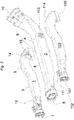
- the Fig. 1 shows as part of an air guide assembly for a motor vehicle, a first air duct 1, wherein the air duct 1 has an elongated channel wall 3, which defines a cavity 5 for conducting the air, which is between at least one air inlet opening 7 and at least one air outlet opening 9.
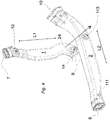
- FIG. 2 shows a separate second air duct 2, wherein the air duct 2 has an elongated channel wall 4, which defines a cavity 6 for guiding the air, which lies between at least one air inlet opening 8 and at least one air outlet opening 10.
- the air ducts 1, 2 can be connected to each other via a first locking connection 11, 12 of a first locking element 11 and a first locking counter-element 12 and at least a second locking connection 13, 14 of a second locking element 13 and a second locking counter-element 14.
- the latching connections 11, 12, 13, 14 are integrally formed from the respective channel wall 3, 4 of the first air duct 1 and the second air duct 2.
- the latching connections 11, 12, 13, 14 are each arranged so that the air ducts 1, 2 can be arranged side by side in their longitudinal extension directions L1, L2, to form a multi-channel air ducting arrangement.
- the in Fig. 2 shown second air duct 2 would have to be rotated accordingly to position the respective air inlet openings 7, 8 of the air ducts 1, 2 next to each other.
- the locking elements 11 and 13 in the illustration according to Fig. 2 no longer visible, are in Fig. 1 and Fig. 2 the corresponding contacting sides of the air ducts 1, 2 shown.
- the second latching element 13 is designed as a latching dome and executed on the second air duct 2.
- the latching dome 13 may also be formed on the first air duct 1.
- the second locking counter-element 14 is formed as a Rastdom technique and formed in accordance with the first air duct 1.
- the second detent counter element 14 is correspondingly designed as a Rastdom technique and formed on the second air duct 2.
- the latching dome 13 has an indentation 20 formed on the dome flank 21 which forms the latching dome 13, the end region of which is at a distance X from the dome flank 21.
- the formation 20 in this case forms a projecting from the mandril 21 locking projection. In the embodiment shown here, a further formation 20 is formed on the mandril 21.
- the Rastdomsuit 14 has an inlet opening 16 with different opening widths 16a, 16b.
- the longest opening width 16a of the inlet opening 16 is greater than or equal to the width b + n ⁇ X (b plus n times X, with n equal to the number of formations) of the locking dome 13 with the formation 20 or with the formations 20.
- the smallest opening width 16b is greater than or equal to the width b of the locking dome 13 and smaller than the width b + n ⁇ X of the locking dome 13 with the formation 20 or with the formations 20.
- the Rastdomness 14 has in the region of the smallest opening width 16 b at least one of the inlet opening 16 undercut formed Forming receptacle 24 for receiving the molding 20 on. Since in the embodiment shown here, the detent dome 13 has two formations 20, two Ausformungsabilityn 24 are provided accordingly.
- the inlet opening 16 is presently oval or elliptical, wherein also a rectangular or a combination of rectangular, oval or elliptical ausgestalteter geometry is conceivable.
- the latching dome 13 having a formation 20 and the latching dome receptacle 14 having an inlet opening 16 are designed and matched to one another in such a way that the second latching connection 13, 14 has a, preferably opposite, relative rotational movement R (cf. Fig. 6 ) of the air ducts 1, 2 can be locked to each other.
- the first air duct 1 and / or the second air duct 2 are manufactured in a blow molding process or in a thermoforming process. To illustrate the first latching connection 11, 12 and the second latching connection 13, 14 are in Fig.1 and in Fig.
- first latching connection 11, 12 may be formed as the second latching connection 13, 14 described above be. This increases the flexibility in the assembly of the air guide assembly, since it does not matter now which of the two locking connections 11, 12, 13, 14 can be latched via a rotational movement.
- the Fig. 3 shows an exploded view of the multi-channel air duct assembly and a representation of the multi-channel air duct assembly prior to their assembly.
- the air ducts 1, 2, 103 are in this case arranged side by side in their longitudinal extension directions, but not yet locked together.
- the in the Figures 1 and 2 Elements described for the reference numerals of the third air duct 103 are respectively increased by the number 100.
- Fig. 4 the air ducts 1 and 2 described in the above figures are shown, in which case first the shaping 20 or the formations 20 of the locking dome 13 in the direction of the longest opening width 16a of the inlet opening 16 of the Rastdom technique 14 is oriented 7 are.
- the orientation of the air ducts 1 and 2 and the shape 20 of the locking dome 13 and the formations 20 of the locking dome 13 in relation to the opening width 16a of the inlet opening 16 of the Rastdomsuit 14 is also in Fig. 5 presented from a different perspective.
- the longitudinal extension directions L1 and L2 of the two air ducts 1, 2 are in this case oriented approximately perpendicular to each other.
- Fig. 6 is the next step for assembling the multi-channel air duct assembly shown by the locking dome 13 inserted through the inlet opening 16 in the Rastdomage 14 and a, preferably opposite, relative rotational movement R of the air ducts 1, 2 to each other, the locking connection 11, 12 is latched by the Forming 20 or the formations 20 is rotated into the forming receptacle 24 or into the shaping receptacles 24 or become.
- the Fig. 6a shows this corresponding connection state in a cross section through the second latching connection 11, 12. In the following step, the first latching connection 11, 12 is locked.
- FIG. 7 is the three-dimensional representation of the multi-channel air duct assembly shown, which is formed by latching interconnected air ducts 1, 2 and 103.
- the air ducts 1, 2, 103 are connected to each other via the snap-in connections 11, 12, 13, 14, 111, 112 and 113, 114 with each other along their longitudinal extension directions.
- At least the second latching element 13 is formed as a latching dome and formed on the first air duct 1 or the second air duct 2 and at least the second locking counter-element 14 is formed as a Rastdom technique and is formed accordingly on the first air duct 1 or the second air duct 2.
- the latching dome 13 has at least one undercut 20 formed on the dome side 21, the end area of which is spaced from the dome flank 21 by a distance X.
- the Rastdomness 14 has an inlet opening 16 with different opening widths 16 a, 16 b, wherein the longest opening width 16a of the inlet opening 16 is greater than or equal to the width b + n ⁇ X of the locking dome 13 with the formation 20 or with the formations 20, and smallest opening width 16b is greater than or equal to the width b of the locking dome 13 and smaller than the width b + n ⁇ X of the locking dome 13 with the molding 20 or 20 with the formations.
- the detent dome 14 has at least one shaping receptacle 24 which undercut the inlet opening 16 to accommodate the formation 20 (cf. Fig. 1 to 3 ).
- the formation 20 of the locking dome 13 or the formations 20 of the locking dome 13 is / are first oriented in the direction of the longest opening width 16a of the inlet opening 16, then the locking dome 13 through the inlet opening 16 in the Rastdom technique 14 and inserted over a, preferably opposite, relative rotational movement R of the air ducts 1, 2 to each other, the second locking connection 13, 14 locked in which the formation 20 or the formations 20 is rotated into the Ausformungsage 24 or into the Ausformungsagen 24 or before then the first latching connection 11, 12 is latched (see. 4 to 6 ).
- first latching connection 11, 12 may be formed as the second latching connection 13, 14 described above. This increases the flexibility in the assembly of the air guide assembly, since it does not matter which of the two locking connections 11, 12, 13, 14 is locked by a rotational movement. Accordingly, the method described above then applies analogously to the first latching connection 11, 12.
Landscapes
- Physics & Mathematics (AREA)
- Thermal Sciences (AREA)
- Engineering & Computer Science (AREA)
- Mechanical Engineering (AREA)
- Air-Conditioning For Vehicles (AREA)
Abstract
Die vorliegende Erfindung bezieht sich auf eine Luftführungsanordnung sowie ein Verfahren zur Herstellung einer Luftführungsanordnung für ein Kraftfahrzeug, umfassend einen ersten Luftführungskanal (1) und wenigstens einen separaten zweiten Luftführungskanal (2), wobei die Luftführungskanäle (1, 2) jeweils eine länglich ausgebildete Kanalwandung (3, 4) aufweisen, die jeweils einen Hohlraum (5, 6) zur Leitung der Luft begrenzt, der zwischen wenigstens einer Lufteinlassöffnung (7, 8) und wenigstens einer Luftauslassöffnung (9, 10) liegt, und wobei die Luftführungskanäle (1, 2) über eine erste Rastverbindung (11, 12) aus einem ersten Rastelement (11) und einem ersten Rastgegenelement (12) und über wenigstens eine zweite Rastverbindung (13, 14) aus einem zweiten Rastelement (13) und einem zweiten Rastgegenelement (14) miteinander verbunden sind, wobei die Rastverbindungen (11, 12, 13, 14) einstückig aus der jeweiligen Kanalwandung (3, 4) des ersten Luftführungskanals (1) und des zweiten Luftführungskanals (2) geformt sind und, dass die Luftführungskanäle (1, 2) in ihren Längserstreckungsrichtungen (L1, L2) nebeneinander angeordnet sind um eine mehrkanalige Luftführungsanordnung zu bilden.The present invention relates to an air duct arrangement and a method for producing an air duct arrangement for a motor vehicle, comprising a first air duct (1) and at least one separate second air duct (2), wherein the air ducts (1, 2) each have an elongated duct wall (1). 3, 4) each defining a cavity (5, 6) for guiding the air, which is located between at least one air inlet opening (7, 8) and at least one air outlet opening (9, 10), and wherein the air guide channels (1, 2 ) via a first latching connection (11, 12) from a first latching element (11) and a first latching counter element (12) and at least one second latching connection (13, 14) of a second latching element (13) and a second latching counter element (14) with each other are connected, wherein the latching connections (11, 12, 13, 14) integrally from the respective channel wall (3, 4) of the first air duct (1) un d of the second air duct (2) are formed and that the air ducts (1, 2) in their longitudinal extension directions (L1, L2) are arranged side by side to form a multi-channel air duct assembly.
Description
Die vorliegende Erfindung betrifft eine Luftführungsanordnung für ein Kraftfahrzeug, umfassend einen ersten Luftführungskanal und wenigstens einen separaten Luftführungskanal, wobei die Luftführungskanäle jeweils eine länglich ausgebildeten Kanalwandung aufweisen, die jeweils einen Hohlraum zur Leitung der Luft begrenzen, der zwischen wenigstens einer Lufteinlassöffnung und wenigstens einer Luftauslassöffnung liegt, und wobei die Luftführungskanäle über eine erste Rastverbindung aus einem ersten Rastelement und einem ersten Rastgegenelement und über wenigstens eine zweite Rastverbindung aus einem zweiten Rastelement und einem zweiten Rastgegenelement miteinander verbunden sind. Ferner Teil der Erfindung ist ein Verfahren zur Herstellung einer Luftführungsanordnung für ein Kraftfahrzeug.The present invention relates to an air duct assembly for a motor vehicle, comprising a first air duct and at least one separate air duct, wherein the air ducts each have an elongated duct wall, each defining a cavity for guiding the air, which is between at least one air inlet opening and at least one air outlet opening , and wherein the air ducts are connected to each other via a first latching connection of a first latching element and a first latching counter element and at least one second latching connection of a second latching element and a second latching counter element. Furthermore, part of the invention is a method for producing an air guide arrangement for a motor vehicle.
Eine gattungsgemäße Luftführungsanordnung für ein Kraftfahrzeug kann beispielhaft der
Die vorliegende Erfindung beschäftigt sich jedoch demgegenüber mit der Herstellung von einer mehrkanaligen Luftführungsanordnung, also einer Luftführungsanordnung, die mehrere Lufteintrittsöffnungen und mehrere Luftaustrittsöffnungen aufweist. Insbesondere bei der Herstellung derartiger Luftführungsanordnungen in einem Blasformverfahren oder in einem Thermoformverfahren (insbesondere Vakuum-Tiefziehen mit zwei Platten) ist es vielfach aufgrund der großen Umformwege und der filigranen Werkzeugwandungen die hierfür notwendig wären unmöglich diese einzelnen Luftführungskanäle in einem einzigen Werkzeug herzustellen, so dass derartige Verfahren für mehrkanalige Luftführungsanordnungen nicht oder nur in Sonderfällen einsetzbar sind. Die Herstellung von komplexen mehrkanaligen Luftführungsanordnungen im Spritzguss scheidet ebenfalls aus, da die hierfür erforderlichen Schieber in dem Werkzeug zur Herstellung der jeweiligen Hohlräume sehr aufwendig sind - wenn die Hohlräume überhaupt hinterschnittfrei über einen derartigen Schieber erzeugbar sind.In contrast, the present invention is concerned with the production of a multi-channel air guide arrangement, ie an air guide arrangement which has a plurality of air inlet openings and a plurality of air outlet openings. In particular, in the production of such air ducting arrangements in a blow molding process or in a thermoforming process (in particular vacuum forming with two plates), it is often impossible to produce these individual air ducts in a single tool due to the large forming paths and the filigree tool walls, so that such Method for multi-channel air ducts not or can only be used in special cases. The production of complex multi-channel air ducting arrangements in injection molding is also ruled out, since the slides required for this purpose in the tool for producing the respective cavities are very expensive - if the cavities can even be generated undercut-free via such a slide.
Im der Anmelderin bekannten Stand der Technik werden die Luftführungskanäle daher jeweils separat in einem Blasformungsverfahren oder in einem Thermoformverfahren hergestellt und auch einzeln in entsprechende Kraftfahrzeuge verbaut. Der Nachteil besteht hierbei darin, dass für jeden einzelnen Luftführungskanal dann eigene Befestigungspunkte im Kraftfahrzeug notwendig sind. Des Weiteren besteht zudem die Gefahr, dass die Luftführungskanäle falsch in das Kraftfahrzeug eingebaut werden können, d.h. das Lufteinlassöffnung und Luftauslassöffnung vertauschbar sind und zudem der Luftführungskanal in seiner bestimmungsgemäßen Orientierung hinsichtlich der Ober- und Unterseite ebenfalls vertauscht werden kann. Bereits bei zwei Luftführungskanälen existieren eine Vielzahl verschiedener Möglichkeiten, die Luftführungskanäle in Relation zueinander zu positionieren. Erhöht man die Zahl der Luftführungskanal bei der mehrkanaligen Luftführungsanordnung, erhöht sich entsprechend die Fehleranfälligkeit bei Einbau der einzelnen Luftführungskanäle in das Kraftfahrzeug.In the prior art known to the applicant, the air ducts are therefore each made separately in a blow molding process or in a thermoforming process and also installed individually in corresponding motor vehicles. The disadvantage here is that for each individual air duct then own attachment points in the vehicle are necessary. Furthermore, there is also the risk that the air ducts can be installed incorrectly in the motor vehicle, i. the air inlet opening and the air outlet opening are interchangeable and also the air duct in its intended orientation with respect to the top and bottom can also be reversed. Even with two air ducts there are a variety of different ways to position the air ducts in relation to each other. Increasing the number of the air duct in the multi-channel air duct assembly, correspondingly increases the susceptibility to failure during installation of the individual air ducts in the motor vehicle.
Aufgabe der vorliegenden Erfindung ist es daher, eine Luftführungsanordnung sowie ein Verfahren zur Herstellung einer Luftführungsanordnung anzugeben, das eine Realisierung einer kostengünstigen und gleichzeitig kompakten mehrkanaligen Luftführungsanordnung ermöglicht.Object of the present invention is therefore to provide an air guide assembly and a method for producing an air duct assembly, which allows realization of a cost-effective and at the same time compact multi-channel air duct arrangement.
Diese Aufgabe wird vorliegend dadurch gelöst, dass die Rastverbindungen einstückig aus der jeweiligen Kanalwandung des ersten Luftführungskanals und des zweiten Luftführungskanals geformt sind und, dass die Luftführungskanäle in ihren Längserstreckungsrichtungen nebeneinander angeordnet sind, um eine mehrkanalige Luftführungsanordnung zu bilden. Die einstückige Ausbildung der Rastverbindungen in den jeweiligen Kanalwandungen des ersten Luftführungskanals und des zweiten Luftführungskanals erlaubt es ohne zusätzliche Verbindungselemente die beiden Luftführungskanäle miteinander zu verbinden. Hierbei sind die Rastverbindungen derart an der jeweiligen Kanalwandung ausgeformt, dass die Luftführungskanäle in ihren Längserstreckungsrichtungen nebeneinander angeordnet miteinander verrastbar sind.This object is achieved in this case in that the latching connections are integrally formed from the respective channel wall of the first air duct and the second air duct and that the air ducts are arranged in their longitudinal extension directions side by side to form a multi-channel air duct assembly. The one-piece design of the locking connections in the respective channel walls of the first air duct and the second air duct allows to connect the two air ducts without additional connecting elements. Here, the latching connections are formed on the respective channel wall in such a way that the air ducts are arranged adjacent to each other in their longitudinal extension directions latched to each other.
Durch die Verbindung der beiden Luftführungskanäle über einstückig aus den jeweiligen Kanalwandungen ausgeformten Rastverbindungen kann eine bereits vollständig vorkonfektionierte mehrkanalige Luftführungsanordnung an den Verbau- bzw. Zusammenbauort des Kraftfahrzeuges geliefert werden und somit die bereits zusammengefügte mehrkanalige Luftführungsanordnung verbausicher in das Kraftfahrzeug integriert werden.By the connection of the two air ducts integrally formed from the respective channel walls latching connections, an already fully prefabricated multi-channel air duct assembly to the installation or assembly of the motor vehicle can be supplied and thus the already assembled multi-channel air duct assembly verbausicher be integrated into the motor vehicle.
Wenigstens das zweite Rastelement kann als Rastdom ausgebildet sein und an dem ersten Luftführungskanal oder dem zweiten Luftführungskanal ausgeformt sein. Der Rastdom kann hierbei einen kreisförmigen oder ovalen oder elliptischen Querschnitt aufweisen.At least the second latching element may be formed as a latching dome and be formed on the first air duct or the second air duct. The latching dome may in this case have a circular or oval or elliptical cross section.
Wenigstens das zweite Rastgegenelement kann als Rastdomaufnahme ausgebildet sein und entsprechend an dem ersten Luftführungskanal oder dem zweiten Luftführungskanal ausgeformt sein. Dies bedeutet, dass wenn der Rastdom an dem ersten Luftführungskanal ausgeformt ist, die Rastdomaufnahme entsprechend an dem zweiten Luftführungskanal ausgeformt ist bzw. wenn der Rastdom an dem zweiten Luftführungskanal ausgeformt ist, die Rastdomaufnahme entsprechend an dem ersten Luftführungskanal ausgeformt ist.At least the second locking counter-element may be formed as a Rastdomaufnahme and be formed in accordance with the first air duct or the second air duct. This means that when the locking dome is formed on the first air duct, the Rastdomaufnahme is formed according to the second air duct or when the Rastdom is formed on the second air duct, the Rastdomaufnahme is formed according to the first air duct.
Der Rastdom kann wenigstens eine den Rastdom hinterschneidend ausgebildete Ausformung auf der Rastdomflanke aufweisen, deren Endbereich mit einem Abstand von der Domflanke beabstandet ist. Die Ausformung kann hierbei insbesondere ein Rastvorsprung sein, der von dem Rastdom oder von der Domflanke absteht.The latching dome may have at least one recess which forms the latching dome on the latching dome flank, the end region of which is at a distance from the dome flank. The formation may in this case be in particular a latching projection which projects from the latching dome or from the dome flank.
Die Rastdomaufnahme kann eine Eintrittsöffnung mit unterschiedlichen Öffnungsbreiten aufweisen. Hierbei kann die längste Öffnungsbreite der Eintrittsöffnung größer oder gleich der Breite des Rastdoms mit der Ausformung oder der Breite des Rastdoms mit den Ausformungen (falls mehrere Ausformungen vorgesehen sind) sein. Die kleinste Öffnungsbreite kann größer oder gleich der Breite des Rastdoms und kleiner als die Breite des Rastdoms mit der Ausformung oder mit den Ausformungen sein. Die Ausformung oder die Ausformungen sind hierbei so gestaltet, dass diese bei einer Orientierung längs bzw. in Richtung der längsten Öffnungsbreite der Eintrittsöffnung in die Eintrittsöffnung einführbar sind.The Rastdomaufnahme may have an inlet opening with different opening widths. Here, the longest opening width of the inlet opening may be greater than or equal to the width of the locking dome with the shape or the width of the locking dome with the formations (if more formations are provided). The smallest opening width may be greater than or equal to the width of the locking dome and smaller than the width of the locking dome with the molding or with the formations. The shape or the formations are in this case designed so that they can be inserted in an orientation along or in the direction of the longest opening width of the inlet opening into the inlet opening.
Die Rastdomaufnahme kann im Bereich der kleinsten Öffnungsbreite wenigstens eine die Eintrittsöffnung hinterschneidend ausgebildete Ausformungsaufnahme zur Aufnahme der Ausformung aufweisen. Für den Fall, dass mehrere Ausformungen vorgesehen sind, sind entsprechend mehrere Ausformungsaufnahmen vorgesehen.The Rastdomaufnahme can in the region of the smallest opening width at least one undercut the inlet opening formed forming receptacle for receiving the Have shape. In the event that a plurality of formations are provided, a plurality of shaping receptacles are provided accordingly.
Die Eintrittsöffnung ist bevorzugt rechteckig, oval und / oder elliptisch und/oder teilweise kreisförmig ausgebildet. Diese Geometrien ermöglichen es, neben der nachfolgend beschriebenen vereinfachten Verbindung der beiden Luftführungskanäle miteinander, zudem in der Verrastposition einen gewissen thermischen Ausgleich bei unterschiedlicher thermischer Ausdehnung der beiden Luftführungskanäle auszugleichen.The inlet opening is preferably rectangular, oval and / or elliptical and / or partially circular. These geometries make it possible, in addition to the simplified connection described below of the two air ducts with each other, also compensate for the Verrastposition a certain thermal compensation with different thermal expansion of the two air ducts.
Bevorzugt ist der eine Ausformung aufweisende Rastdom und die eine Eintrittsöffnung aufweisende Rastdomaufnahme so ausgebildet und aufeinander abgestimmt, dass die zweite Rastverbindung über eine relative Drehbewegung der Luftführungen zueinander verrastbar ist. Die relative Drehbewegung der Luftführungen zueinander erfolgt hierbei bevorzugt gegenläufig. Eine derartige Ausgestaltung der Luftführungsanordnung ermöglicht es, die beiden Luftführungskanäle zunächst derart zueinander zu positionieren, dass deren Längserstreckungsrichtungen in etwa senkrecht aufeinander stehen, um dann den Rastdom in die Eintrittsöffnung der Rastdomaufnahme einzuführen, um dann über eine Drehbewegung der Luftführung relativ zueinander die zweite Rastverbindung zu verrasten, indem die Ausformung des Rastdoms in die entsprechende Ausformungsaufnahme der Rastdomaufnahme einrastet. Erst dann erfolgt eine Verrastung der ersten Rastverbindung. Eine derartige Verbindung der beiden Luftführungskanäle über eine Drehbewegung ermöglicht es die beiden Luftführungskanäle zu verbinden, ohne das eine Druck- bzw. Quetschbelastung auf die Wandungen der Luftführungskanäle ausgeübt werden muss. Insbesondere wenn die Rastverbindung sich in einem Bereich der Luftführungskanäle befindet, bei dem eine Stützung des Rastdoms bzw. der Rastdomaufnahme von innerhalb des jeweiligen Luftführungskanals bzw. der beiden Luftführungskanäle nicht möglich ist, besteht ansonsten die Gefahr, dass es zu einer Beschädigung der Rastverbindung kommt bzw. aufgrund der fehlenden Gegenkräfte die Rastverbindung gar nicht erst hergestellt werden kann, da der Rastdom bzw. die Rastdomaufnahme der für die Herstellung der Rastverbindung erforderlichen Druckkraft ausweicht.The detent dome having a shape and the detent dome receiving an inlet opening are preferably designed and matched to one another such that the second detent connection can be latched to one another via a relative rotational movement of the air guides. The relative rotational movement of the air ducts relative to one another preferably takes place in opposite directions. Such an embodiment of the air duct arrangement makes it possible to initially position the two air ducts in such a way that their longitudinal directions are approximately perpendicular to each other, then introduce the latching dome into the inlet opening of the Rastdomaufnahme, then about a rotational movement of the air duct relative to each other, the second locking connection lock in place by the formation of the locking dome engages in the corresponding form-receiving the Rastdomaufnahme. Only then is a latching of the first latching connection. Such a connection of the two air ducts via a rotary movement makes it possible to connect the two air ducts without a pressure or crushing load must be exerted on the walls of the air ducts. In particular, if the locking connection is located in a region of the air ducts, in which a support of the locking dome or the Rastdomaufnahme of within the respective air duct or the two air ducts is not possible, otherwise there is a risk that it comes to damage the locking connection or Due to the lack of opposing forces, the latching connection can not be produced at all, since the latching dome or the latching dome receiver avoids the pressure force required for the production of the latching connection.
Besonders bevorzugt ist bzw. sind der erste Luftführungskanal und / oder der zweite Luftführungskanal in einem Blasformverfahren oder in einem Thermoformverfahren (insbesondere einem Vakuum-Tiefziehen mit zwei Platten) hergestellt. Die Luftführungskanäle bestehen bevorzugt aus einem thermoplastischen Kunststoffmaterial. Das Kunststoffmaterial kann insbesondere ein Polyolefin (bevorzugt Polypropylen oder Polyethylen) oder ein Polyamid umfassen.Particularly preferably, the first air duct and / or the second air duct are or are produced in a blow-molding process or in a thermoforming process (in particular a vacuum thermoforming with two plates). The air ducts are preferably made of a thermoplastic material. The plastic material may in particular comprise a polyolefin (preferably polypropylene or polyethylene) or a polyamide.
Auch die erste Rastverbindung kann wie die vorstehend beschriebene zweite Rastverbindung ausgebildet sein. Dies erhöht die Flexibilität beim Zusammenbau der Luftführungsanordnung, da es nunmehr egal ist welche der beiden Rastverbindungen über eine Drehbewegung verrastbar ist.Also, the first latching connection may be formed as the second latching connection described above. This increases the flexibility in the assembly of the air guide assembly, since it does not matter now which of the two locking connections can be latched via a rotational movement.
Die vorliegende Erfindung umfasst ferner ein Verfahren zur Herstellung einer Luftführungsanordnung für ein Kraftfahrzeug, insbesondere zur Herstellung einer erfindungsgemäßen Luftführungsanordnung wie vorstehend, oder wie in den Ansprüchen 1 bis 9, beschrieben.The present invention further comprises a method for producing an air-guiding arrangement for a motor vehicle, in particular for producing an air-guiding arrangement according to the invention as above, or as described in
Das Verfahren zur Herstellung einer Luftführungsanordnung für ein Kraftfahrzeug mit einem ersten Luftführungskanal und wenigstens einem separaten zweite Luftführungskanal, wobei die Luftführungskanäle jeweils eine länglich ausgebildete Kanalwandung aufweisen, die jeweils einen Hohlraum zur Leitung der Luft begrenzen, der zwischen wenigstens einer Lufteinlassöffnung und wenigstens einer Luftauslassöffnung liegt, und wobei die Luftführungskanäle über eine erste Rastverbindung aus einem ersten Rastelement und einem ersten Rastgegenelement und über wenigstens eine zweite Rastverbindung aus einem zweiten Rastelement und einem zweiten Rastgegenelement miteinander verbindbar sind, wobei die Rastverbindungen einstückig aus der jeweiligen Kanalwandung des ersten Luftführungskanals und des zweiten Luftführungskanals geformt sind, umfasst die folgenden Schritte:
- Verbinden der Rastverbindungen, so dass die Luftführungskanäle in ihren Längserstreckungsrichtungen nebeneinander angeordnet sind um eine mehrkanalige Luftführungsanordnung zu bilden.
- Connecting the locking connections, so that the air ducts are arranged side by side in their longitudinal extension directions to form a multi-channel air duct assembly.
Das Verfahren zur Herstellung einer Luftführungsanordnung kann hierbei ferner wie folgt ausgebildet sein:
- Wenigstens das zweite Rastelement ist als Rastdom ausgebildet und an dem ersten Luftführungskanal oder dem zweiten Luftführungskanal ausgeformt und das wenigstens zweite Rastgegenelement ist als Rastdomaufnahme ausgebildet und ist entsprechend an dem ersten Luftführungskanal oder dem zweiten Luftführungskanal ausgeformt und, der Rastdom weist wenigstens eine den Rastdom hinterschneidend ausgebildete Ausformung auf der Domflanke auf, deren Endbereiche mit einem Abstand von der Domflanke beabstandet ist und, die Rastdomaufnahme weist eine Eintrittsöffnung mit unterschiedlichen Öffnungsbreiten auf, wobei die längste Öffnungsbreite der Eintrittsöffnung größer oder gleich der Breite des Rastdoms mit der Ausformung oder mit den Ausformungen ist, und die kleinste Öffnungsbreite größer oder gleich der Breite des Rastdoms und kleiner als die Breite des Rastdoms mit der Ausformung oder mit den Ausformungen ist und, die Rastdomaufnahme im Bereich der kleinsten Öffnungsbreite wenigstens eine die Eintrittsöffnung hinterschneidend ausgebildete Ausformungsaufnahme zur Aufnahme der Ausformung aufweist, wobei die Ausformung des Rastdoms oder die Ausformungen des Rastdoms zunächst in Richtung der längsten Öffnungsbreite der Eintrittsöffnung orientiert, dann der Rastdom durch die Eintrittsöffnung in die Rastdomaufnahme eingeschoben und über eine, vorzugsweise gegenläufige, relative Drehbewegung der Luftführungen zueinander die zweite Rastverbindung verrastet wird, indem die Ausformung oder die Ausformungen bis in die Ausformungsaufnahme oder bis in die Ausformungsaufnahmen gedreht wird oder werden, bevor dann die erste Rastverbindung verrastet wird.
- At least the second latching element is designed as a latching dome and formed on the first air duct or the second air duct and the at least second locking counter-element is designed as Rastdomaufnahme and is formed accordingly on the first air duct or the second air duct and the Rastdom has at least one Rastdom undercut formed formation on the Dom flank, the end portions of which is spaced a distance from the Domblanke and, the Rastdomaufnahme has an inlet opening with different opening widths, wherein the longest opening width of the inlet opening is greater than or equal to the width of the detent dome with the molding or with the formations, and the smallest opening width is greater than or equal to the width of the locking dome and smaller than the width of the locking dome with the molding or with the formations and, the Rastdomaufnahme in the region of the smallest opening width at least one undercut the inlet opening formed forming receptacle for receiving the molding, wherein the molding the Rastdoms or the formations of the locking dome initially oriented in the direction of the longest opening width of the inlet opening, then the locking dome inserted through the inlet opening in the Rastdomaufnahme and via a, preferably opposite, relative rotational movement Un the air ducts to each other, the second latching connection is latched by the molding or the formations is rotated to the molding receptacle or to the formations recordings or before then the first snap-in connection is latched.
Die Drehbewegung kann insbesondere eine gegenläufige Drehbewegung sein.The rotational movement can be in particular an opposite rotational movement.
Auch die erste Rastverbindung kann wie die vorstehend beschriebene zweite Rastverbindung ausgebildet sein. Dies erhöht die Flexibilität beim Zusammenbau der Luftführungsanordnung, da es nunmehr egal ist welche der beiden Rastverbindungen über eine Drehbewegung verrastbar ist. Entsprechend gilt das vorstehend beschriebene Verfahren dann analog für die erste Rastverbindung.Also, the first latching connection may be formed as the second latching connection described above. This increases the flexibility in the assembly of the air guide assembly, since it does not matter now which of the two locking connections can be latched via a rotational movement. Accordingly, the method described above then applies analogously to the first latching connection.
Die Erfindung wird anhand der lediglich Ausführungsbeispiele darstellenden Zeichnungen näher erläutert, wobei gleiche oder funktionsgleiche Elemente mit den gleichen Bezugszeichen versehen sind. Die Figuren zeigen:
- Fig. 1
- eine Seitenansicht eines ersten Luftführungskanals;
- Fig. 2
- eine Seitenansicht eines zweiten Luftführungskanals;
- Fig. 3
- eine dreidimensionale Explosionsdarstellung einer mehrkanaligen Luftführungsanordnung aus einem ersten, zweiten und einem dritten Luftführungskanal;
- Fig. 4
- die Positionierung eines ersten Luftführungskanals in Relation zu einem zweiten Luftführungskanal vor dem Verrasten einer zweiten Rastverbindung;
- Fig. 5
- die Darstellung gemäß
Fig. 4 aus einer anderen Perspektive; - Fig. 6
- die beiden Luftführungskanäle aus
Fig. 4 und 5 , bei denen Rastdom und Rastdomaufnahme ineinander geschoben sind; - Fig. 6a
- eine Schnittdarstellung durch die zweite Rastverbindung in der endgültigen Verrastposition;
- Fig. 7
- eine dreidimensionale Darstellung von in ihren Längserstreckungen nebeneinander angeordneten Luftführungskanälen, die über Rastverbindungen miteinander verbunden sind.
- Fig. 1
- a side view of a first air duct;
- Fig. 2
- a side view of a second air duct;
- Fig. 3
- a three-dimensional exploded view of a multi-channel air duct assembly of a first, second and a third air duct;
- Fig. 4
- the positioning of a first air duct in relation to a second air duct before the latching of a second latching connection;
- Fig. 5
- the representation according to
Fig. 4 from another perspective; - Fig. 6
- the two air ducts off
Fig. 4 and5 in which Rastdom and Rastdomaufnahme are pushed together; - Fig. 6a
- a sectional view through the second latching connection in the final latching position;
- Fig. 7
- a three-dimensional representation of their longitudinal extent juxtaposed air ducts, which are interconnected via snap-in connections.
Die
Ein weiterer Teil der Luftführungsanordnung für ein Kraftfahrzeug ist in
Die
In
In
In der
Ein Verfahren zur Herstellung einer Luftführungsanordnung für ein Kraftfahrzeug, insbesondere einer Luftführungsanordnung wie vorstehend beschrieben, mit einem ersten Luftführungskanal 1 und mit wenigstens einem separaten zweiten Luftführungskanal 2, wobei die Luftführungskanäle 1, 2 jeweils eine länglich ausgebildete Kanalwandung 3, 4 aufweisen, die jeweils einen Hohlraum 5, 6 zur Leitung der Luft begrenzt, der zwischen wenigstens einer Lufteinlassöffnung 7, 8 und wenigstens einer Luftauslassöffnung 9, 10 liegt, und wobei die Luftführungskanäle 1, 2 über eine erste Rastverbindung 11, 12 aus einem ersten Rastelement 11 und einem ersten Rastgegenelement 12 und über wenigstens eine zweite Rastverbindung 13, 14 aus einem zweiten Rastelement 13 und einem zweiten Rastgegenelement 14 miteinander verbindbar sind, wobei die Rastverbindungen 11, 12, 13, 14 einstückig aus der jeweiligen Kanalwandung 3, 4 des ersten Luftführungskanals 1 und des zweiten Luftführungskanals 2 geformt sind, umfasst die folgenden Schritte:
Verbinden der Rastverbindungen Luftführungskanäle
- Connecting the
locking connections air ducts
Wenigstens das zweite Rastelement 13 ist als Rastdom ausgebildet und an dem ersten Luftführungskanal 1 oder dem zweiten Luftführungskanal 2 ausgeformt und, wenigstens das zweite Rastgegenelement 14 ist als Rastdomaufnahme ausgebildet und ist entsprechend an dem ersten Luftführungskanal 1 oder dem zweiten Luftführungskanal 2 ausgeformt. Der Rastdom 13 weist wenigstens eine den Rastdom 13 hinterschneidend ausgebildete Ausformung 20 auf der Domflanke 21 auf, deren Endbereich mit einem Abstand X von der Domflanke 21 beabstandet ist. Die Rastdomaufnahme 14 weist eine Eintrittsöffnung 16 mit unterschiedlichen Öffnungsbreiten 16a, 16 b auf, wobei die längste Öffnungsbreite 16a der Eintrittsöffnung 16 größer oder gleich der Breite b+n·X des Rastdoms 13 mit der Ausformung 20 oder mit den Ausformungen 20 ist, und die kleinste Öffnungsbreite 16b größer oder gleich der Breite b des Rastdoms 13 und kleiner als die Breite b+n·X des Rastdoms 13 mit der Ausformung 20 oder mit den Ausformungen 20 ist. Die Rastdomaufnahme 14 weist im Bereich der kleinsten Öffnungsbreite 16b wenigstens eine die Eintrittsöffnung 16 hinterschneidend ausgebildete Ausformungsaufnahme 24 zur Aufnahme der Ausformung 20 aufweist (vgl.
Auch die erste Rastverbindung 11, 12 kann wie die vorstehend beschriebene zweite Rastverbindung 13, 14 ausgebildet sein. Dies erhöht die Flexibilität beim Zusammenbau der Luftführungsanordnung, da es nunmehr egal ist welche der beiden Rastverbindungen 11, 12, 13, 14 über eine Drehbewegung verrastet wird. Entsprechend gilt das vorstehend beschriebene Verfahren dann analog für die erste Rastverbindung 11, 12.Also, the
Claims (11)
und wobei die Luftführungskanäle (1, 2) über eine erste Rastverbindung (11, 12) aus einem ersten Rastelement (11) und einem ersten Rastgegenelement (12) und über wenigstens eine zweite Rastverbindung (13, 14) aus einem zweiten Rastelement (13) und einem zweiten Rastgegenelement (14) miteinander verbunden sind,
dadurch gekennzeichnet, dass
and wherein the air ducts (1, 2) comprise a first latching connection (11, 12) comprising a first latching element (11) and a first latching counter element (12) and at least one second latching connection (13, 14) comprising a second latching element (13). and a second locking counter element (14) are interconnected,
characterized in that
umfassend die folgenden Schritte:
comprising the following steps:
wobei die Ausformung (20) des Rastdoms (13) oder die Ausformungen (20) des Rastdoms (13) zunächst in Richtung der längsten Öffnungsbreite (16a) der Eintrittsöffnung (16) orientiert, dann der Rastdom (13) durch die Eintrittsöffnung (16) in die Rastdomaufnahme (14) eingeschoben und über eine, vorzugsweise gegenläufige, relative Drehbewegung (R) der Luftführungen (1, 2) zueinander die zweite Rastverbindung (13, 14) verrastet wird in dem die Ausformung (20) oder die Ausformungen (20) bis in die Ausformungsaufnahme (24) oder bis in die Ausformungsaufnahmen (24) gedreht wird oder werden, bevor dann die erste Rastverbindung (11, 12) verrastet wird.A method for producing an air duct arrangement according to claim 10, characterized in that at least the second latching element (13) is designed as a latching dome and on the first air duct (1) or the second air duct (2) is formed and that at least the second locking counter element (14 ) is formed as a Rastdomaufnahme and according to the first air duct (1) or the second air duct (2) is formed and that the Rastdom (13) at least one Rastdom (13) undercut formed shaping (20) on the Domanke (21) has, whose end portion with a distance (X) from the Domanke (21) is spaced and that the Rastdomaufnahme (14) has an inlet opening (16) with different opening widths (16 a, 16 b), wherein the longest opening width (16 a) of the Entry opening (16) is greater than or equal to the width (b + n · X) of the locking dome (13) with the formation (20) or with the formations (20), and smallest opening width (16b) greater than or equal to the width (b) of the locking dome (13) and smaller than the width (b + n × X) of the locking dome (13) with the formation (20) or with the formations (20) and that the Rastdomaufnahme (14) in the region of the smallest opening width (16b) at least one of Having inlet opening (16) undercut educated receiving receptacle (24) for receiving the molding (20),
wherein the formation (20) of the locking dome (13) or the formations (20) of the locking dome (13) initially oriented in the direction of the longest opening width (16a) of the inlet opening (16), then the locking dome (13) through the inlet opening (16) pushed into the locking dome (14) and via a, preferably opposite, relative rotational movement (R) of the air ducts (1, 2) to each other the second latching connection (13, 14) is latched in which the formation (20) or the formations (20) is rotated or until the molding receptacle (24) or to the shaping receptacles (24), before then the first latching connection (11, 12) is locked.
Applications Claiming Priority (1)
| Application Number | Priority Date | Filing Date | Title |
|---|---|---|---|
| DE102015108341.8A DE102015108341A1 (en) | 2015-05-27 | 2015-05-27 | Air duct assembly for a motor vehicle and method for producing an air duct assembly for a motor vehicle |
Publications (2)
| Publication Number | Publication Date |
|---|---|
| EP3098100A1 true EP3098100A1 (en) | 2016-11-30 |
| EP3098100B1 EP3098100B1 (en) | 2020-04-29 |
Family
ID=55527856
Family Applications (1)
| Application Number | Title | Priority Date | Filing Date |
|---|---|---|---|
| EP16159868.5A Active EP3098100B1 (en) | 2015-05-27 | 2016-03-11 | Air guidance system for a motor vehicle and method for producing an air guidance system for a motor vehicle |
Country Status (2)
| Country | Link |
|---|---|
| EP (1) | EP3098100B1 (en) |
| DE (1) | DE102015108341A1 (en) |
Cited By (1)
| Publication number | Priority date | Publication date | Assignee | Title |
|---|---|---|---|---|
| US20220065554A1 (en) * | 2020-09-03 | 2022-03-03 | Ti Automotive Technology Center Gmbh | Pipe arrangement for transporting temperature control media |
Citations (5)
| Publication number | Priority date | Publication date | Assignee | Title |
|---|---|---|---|---|
| GB2332887A (en) * | 1997-11-19 | 1999-07-07 | Textron Automotive U K | Fluid reservoir and air duct |
| WO2002032702A2 (en) * | 2000-10-18 | 2002-04-25 | Honda Giken Kogyo Kabushiki Kaisha | Air conditioning duct and method for mounting same |
| DE10137998A1 (en) | 2001-08-02 | 2003-02-13 | Bayerische Motoren Werke Ag | Snap connection structure and line device provided with it |
| EP2062759A1 (en) * | 2007-11-20 | 2009-05-27 | Seat, S.A. | Conditioning air feeder for glove compartments of automobiles |
| US20110009045A1 (en) * | 2009-07-09 | 2011-01-13 | Beckley Daniel V | Vehicular Interior Assembly |
Family Cites Families (3)
| Publication number | Priority date | Publication date | Assignee | Title |
|---|---|---|---|---|
| US20090243322A1 (en) * | 2008-04-01 | 2009-10-01 | David F. MacNeil | Vehicle cargo space liner with snap-connected extension |
| DE102008045595B4 (en) * | 2008-09-03 | 2020-09-03 | Audi Ag | Automotive air filter system and associated assembly process |
| CH702954B1 (en) * | 2010-04-12 | 2014-08-15 | Schwanden Kunststoff | Curved double pipe unit. |
-
2015
- 2015-05-27 DE DE102015108341.8A patent/DE102015108341A1/en not_active Withdrawn
-
2016
- 2016-03-11 EP EP16159868.5A patent/EP3098100B1/en active Active
Patent Citations (5)
| Publication number | Priority date | Publication date | Assignee | Title |
|---|---|---|---|---|
| GB2332887A (en) * | 1997-11-19 | 1999-07-07 | Textron Automotive U K | Fluid reservoir and air duct |
| WO2002032702A2 (en) * | 2000-10-18 | 2002-04-25 | Honda Giken Kogyo Kabushiki Kaisha | Air conditioning duct and method for mounting same |
| DE10137998A1 (en) | 2001-08-02 | 2003-02-13 | Bayerische Motoren Werke Ag | Snap connection structure and line device provided with it |
| EP2062759A1 (en) * | 2007-11-20 | 2009-05-27 | Seat, S.A. | Conditioning air feeder for glove compartments of automobiles |
| US20110009045A1 (en) * | 2009-07-09 | 2011-01-13 | Beckley Daniel V | Vehicular Interior Assembly |
Cited By (4)
| Publication number | Priority date | Publication date | Assignee | Title |
|---|---|---|---|---|
| US20220065554A1 (en) * | 2020-09-03 | 2022-03-03 | Ti Automotive Technology Center Gmbh | Pipe arrangement for transporting temperature control media |
| EP3964372A1 (en) * | 2020-09-03 | 2022-03-09 | TI Automotive Technology Center GmbH | Tube assembly for transporting temperature control media |
| EP3964374A1 (en) * | 2020-09-03 | 2022-03-09 | TI Automotive Technology Center GmbH | Tube assembly for transporting temperature control media |
| CN114321542A (en) * | 2020-09-03 | 2022-04-12 | Ti汽车技术中心有限责任公司 | Pipeline device for conveying temperature control medium |
Also Published As
| Publication number | Publication date |
|---|---|
| DE102015108341A1 (en) | 2016-12-01 |
| EP3098100B1 (en) | 2020-04-29 |
Similar Documents
| Publication | Publication Date | Title |
|---|---|---|
| DE102007040812B4 (en) | Folding type cable protection and routing device | |
| EP1254043B1 (en) | Structural component for a motor vehicle | |
| EP2945813B1 (en) | Ventilation mesh with air conducting element, and method for producing such a ventilation mesh | |
| DE102008016490A1 (en) | Cable protection and guiding device | |
| DE10044379A1 (en) | Component for a motor vehicle | |
| DE3221676A1 (en) | DEVICE FOR INTERCHANGING TWO PARTS BEFORE THEIR OPTIONAL REMOVAL | |
| DE102015113538A1 (en) | HAVC channel with pivoting bow | |
| DE10046120A1 (en) | Instrument carrier for use in motor vehicle | |
| DE102005056891B3 (en) | Air ducts connecting device for use in motor vehicle, has connecting unit for transition of air flow between ducts, where different notch positions are selected for connecting unit relative to one of ducts and are defined by fastening unit | |
| DE102013000628B4 (en) | Holding frame of a fresh air flap of a motor vehicle and fresh air flap with holding frame | |
| EP3366985B1 (en) | Vehicle headlamp with a cable channel and production method for producing the same | |
| DE102010032618A1 (en) | Blow mold for use in construction kit for manufacturing of containers, particularly canisters, has two tool components, particularly tool halves, which are movable against each other for opening and closing tool | |
| DE10147621B4 (en) | Fastening arrangement for a lateral end region of a front or rear bumper of a vehicle | |
| EP3098100A1 (en) | Air guidance system for a motor vehicle and method for producing an air guidance system for a motor vehicle | |
| EP3036806A1 (en) | Cable duct and method for producing a three-dimensional cable duct | |
| WO2008119706A1 (en) | Method for the production of a sealing assembly, in particular for a motor vehicle, having a sealing element and a support, and such a sealing assembly | |
| DE202014002016U1 (en) | air vents | |
| DE60222256T2 (en) | DEVICE FOR MECHANICAL ACTUATION OF ELEMENTS FOR VEHICLE VENTILATION | |
| WO2017005352A1 (en) | Roof module for a motor vehicle | |
| EP3587217A1 (en) | Steering wheel; fastening system for covering components of a steering wheel and method for producing a steering wheel | |
| EP3034337B1 (en) | Air conduit system for a motor vehicle | |
| EP4196330B1 (en) | Extruded part, battery housing having an extruded part, method for producing an extruded part, extrusion die | |
| DE10210968C1 (en) | Extruded profile for motor vehicle sliding roof has two interlocking rails section with projecting strip on one engaging correspondingly shaped recess in other | |
| DE102017123459A1 (en) | Radiator grille for use in a motor vehicle | |
| DE102017007203A1 (en) | Stem for a motor vehicle radiator |
Legal Events
| Date | Code | Title | Description |
|---|---|---|---|
| PUAI | Public reference made under article 153(3) epc to a published international application that has entered the european phase |
Free format text: ORIGINAL CODE: 0009012 |
|
| AK | Designated contracting states |
Kind code of ref document: A1 Designated state(s): AL AT BE BG CH CY CZ DE DK EE ES FI FR GB GR HR HU IE IS IT LI LT LU LV MC MK MT NL NO PL PT RO RS SE SI SK SM TR |
|
| AX | Request for extension of the european patent |
Extension state: BA ME |
|
| STAA | Information on the status of an ep patent application or granted ep patent |
Free format text: STATUS: REQUEST FOR EXAMINATION WAS MADE |
|
| 17P | Request for examination filed |
Effective date: 20170530 |
|
| RBV | Designated contracting states (corrected) |
Designated state(s): AL AT BE BG CH CY CZ DE DK EE ES FI FR GB GR HR HU IE IS IT LI LT LU LV MC MK MT NL NO PL PT RO RS SE SI SK SM TR |
|
| STAA | Information on the status of an ep patent application or granted ep patent |
Free format text: STATUS: EXAMINATION IS IN PROGRESS |
|
| 17Q | First examination report despatched |
Effective date: 20181010 |
|
| GRAP | Despatch of communication of intention to grant a patent |
Free format text: ORIGINAL CODE: EPIDOSNIGR1 |
|
| STAA | Information on the status of an ep patent application or granted ep patent |
Free format text: STATUS: GRANT OF PATENT IS INTENDED |
|
| INTG | Intention to grant announced |
Effective date: 20200131 |
|
| GRAS | Grant fee paid |
Free format text: ORIGINAL CODE: EPIDOSNIGR3 |
|
| GRAA | (expected) grant |
Free format text: ORIGINAL CODE: 0009210 |
|
| STAA | Information on the status of an ep patent application or granted ep patent |
Free format text: STATUS: THE PATENT HAS BEEN GRANTED |
|
| AK | Designated contracting states |
Kind code of ref document: B1 Designated state(s): AL AT BE BG CH CY CZ DE DK EE ES FI FR GB GR HR HU IE IS IT LI LT LU LV MC MK MT NL NO PL PT RO RS SE SI SK SM TR |
|
| REG | Reference to a national code |
Ref country code: GB Ref legal event code: FG4D Free format text: NOT ENGLISH |
|
| REG | Reference to a national code |
Ref country code: CH Ref legal event code: EP |
|
| REG | Reference to a national code |
Ref country code: AT Ref legal event code: REF Ref document number: 1262764 Country of ref document: AT Kind code of ref document: T Effective date: 20200515 |
|
| REG | Reference to a national code |
Ref country code: DE Ref legal event code: R096 Ref document number: 502016009711 Country of ref document: DE |
|
| REG | Reference to a national code |
Ref country code: IE Ref legal event code: FG4D Free format text: LANGUAGE OF EP DOCUMENT: GERMAN |
|
| REG | Reference to a national code |
Ref country code: NL Ref legal event code: MP Effective date: 20200429 |
|
| REG | Reference to a national code |
Ref country code: LT Ref legal event code: MG4D |
|
| PG25 | Lapsed in a contracting state [announced via postgrant information from national office to epo] |
Ref country code: PT Free format text: LAPSE BECAUSE OF FAILURE TO SUBMIT A TRANSLATION OF THE DESCRIPTION OR TO PAY THE FEE WITHIN THE PRESCRIBED TIME-LIMIT Effective date: 20200831 Ref country code: GR Free format text: LAPSE BECAUSE OF FAILURE TO SUBMIT A TRANSLATION OF THE DESCRIPTION OR TO PAY THE FEE WITHIN THE PRESCRIBED TIME-LIMIT Effective date: 20200730 Ref country code: IS Free format text: LAPSE BECAUSE OF FAILURE TO SUBMIT A TRANSLATION OF THE DESCRIPTION OR TO PAY THE FEE WITHIN THE PRESCRIBED TIME-LIMIT Effective date: 20200829 Ref country code: SE Free format text: LAPSE BECAUSE OF FAILURE TO SUBMIT A TRANSLATION OF THE DESCRIPTION OR TO PAY THE FEE WITHIN THE PRESCRIBED TIME-LIMIT Effective date: 20200429 Ref country code: NO Free format text: LAPSE BECAUSE OF FAILURE TO SUBMIT A TRANSLATION OF THE DESCRIPTION OR TO PAY THE FEE WITHIN THE PRESCRIBED TIME-LIMIT Effective date: 20200729 Ref country code: FI Free format text: LAPSE BECAUSE OF FAILURE TO SUBMIT A TRANSLATION OF THE DESCRIPTION OR TO PAY THE FEE WITHIN THE PRESCRIBED TIME-LIMIT Effective date: 20200429 Ref country code: LT Free format text: LAPSE BECAUSE OF FAILURE TO SUBMIT A TRANSLATION OF THE DESCRIPTION OR TO PAY THE FEE WITHIN THE PRESCRIBED TIME-LIMIT Effective date: 20200429 |
|
| RAP2 | Party data changed (patent owner data changed or rights of a patent transferred) |
Owner name: REHAU AG + CO |
|
| PG25 | Lapsed in a contracting state [announced via postgrant information from national office to epo] |
Ref country code: BG Free format text: LAPSE BECAUSE OF FAILURE TO SUBMIT A TRANSLATION OF THE DESCRIPTION OR TO PAY THE FEE WITHIN THE PRESCRIBED TIME-LIMIT Effective date: 20200729 Ref country code: LV Free format text: LAPSE BECAUSE OF FAILURE TO SUBMIT A TRANSLATION OF THE DESCRIPTION OR TO PAY THE FEE WITHIN THE PRESCRIBED TIME-LIMIT Effective date: 20200429 Ref country code: RS Free format text: LAPSE BECAUSE OF FAILURE TO SUBMIT A TRANSLATION OF THE DESCRIPTION OR TO PAY THE FEE WITHIN THE PRESCRIBED TIME-LIMIT Effective date: 20200429 Ref country code: HR Free format text: LAPSE BECAUSE OF FAILURE TO SUBMIT A TRANSLATION OF THE DESCRIPTION OR TO PAY THE FEE WITHIN THE PRESCRIBED TIME-LIMIT Effective date: 20200429 |
|
| PG25 | Lapsed in a contracting state [announced via postgrant information from national office to epo] |
Ref country code: NL Free format text: LAPSE BECAUSE OF FAILURE TO SUBMIT A TRANSLATION OF THE DESCRIPTION OR TO PAY THE FEE WITHIN THE PRESCRIBED TIME-LIMIT Effective date: 20200429 Ref country code: AL Free format text: LAPSE BECAUSE OF FAILURE TO SUBMIT A TRANSLATION OF THE DESCRIPTION OR TO PAY THE FEE WITHIN THE PRESCRIBED TIME-LIMIT Effective date: 20200429 |
|
| PG25 | Lapsed in a contracting state [announced via postgrant information from national office to epo] |
Ref country code: SM Free format text: LAPSE BECAUSE OF FAILURE TO SUBMIT A TRANSLATION OF THE DESCRIPTION OR TO PAY THE FEE WITHIN THE PRESCRIBED TIME-LIMIT Effective date: 20200429 Ref country code: EE Free format text: LAPSE BECAUSE OF FAILURE TO SUBMIT A TRANSLATION OF THE DESCRIPTION OR TO PAY THE FEE WITHIN THE PRESCRIBED TIME-LIMIT Effective date: 20200429 Ref country code: IT Free format text: LAPSE BECAUSE OF FAILURE TO SUBMIT A TRANSLATION OF THE DESCRIPTION OR TO PAY THE FEE WITHIN THE PRESCRIBED TIME-LIMIT Effective date: 20200429 Ref country code: DK Free format text: LAPSE BECAUSE OF FAILURE TO SUBMIT A TRANSLATION OF THE DESCRIPTION OR TO PAY THE FEE WITHIN THE PRESCRIBED TIME-LIMIT Effective date: 20200429 Ref country code: RO Free format text: LAPSE BECAUSE OF FAILURE TO SUBMIT A TRANSLATION OF THE DESCRIPTION OR TO PAY THE FEE WITHIN THE PRESCRIBED TIME-LIMIT Effective date: 20200429 Ref country code: CZ Free format text: LAPSE BECAUSE OF FAILURE TO SUBMIT A TRANSLATION OF THE DESCRIPTION OR TO PAY THE FEE WITHIN THE PRESCRIBED TIME-LIMIT Effective date: 20200429 Ref country code: ES Free format text: LAPSE BECAUSE OF FAILURE TO SUBMIT A TRANSLATION OF THE DESCRIPTION OR TO PAY THE FEE WITHIN THE PRESCRIBED TIME-LIMIT Effective date: 20200429 |
|
| REG | Reference to a national code |
Ref country code: DE Ref legal event code: R097 Ref document number: 502016009711 Country of ref document: DE |
|
| PG25 | Lapsed in a contracting state [announced via postgrant information from national office to epo] |
Ref country code: PL Free format text: LAPSE BECAUSE OF FAILURE TO SUBMIT A TRANSLATION OF THE DESCRIPTION OR TO PAY THE FEE WITHIN THE PRESCRIBED TIME-LIMIT Effective date: 20200429 Ref country code: SK Free format text: LAPSE BECAUSE OF FAILURE TO SUBMIT A TRANSLATION OF THE DESCRIPTION OR TO PAY THE FEE WITHIN THE PRESCRIBED TIME-LIMIT Effective date: 20200429 |
|
| PLBE | No opposition filed within time limit |
Free format text: ORIGINAL CODE: 0009261 |
|
| STAA | Information on the status of an ep patent application or granted ep patent |
Free format text: STATUS: NO OPPOSITION FILED WITHIN TIME LIMIT |
|
| 26N | No opposition filed |
Effective date: 20210201 |
|
| PG25 | Lapsed in a contracting state [announced via postgrant information from national office to epo] |
Ref country code: SI Free format text: LAPSE BECAUSE OF FAILURE TO SUBMIT A TRANSLATION OF THE DESCRIPTION OR TO PAY THE FEE WITHIN THE PRESCRIBED TIME-LIMIT Effective date: 20200429 |
|
| PG25 | Lapsed in a contracting state [announced via postgrant information from national office to epo] |
Ref country code: MC Free format text: LAPSE BECAUSE OF FAILURE TO SUBMIT A TRANSLATION OF THE DESCRIPTION OR TO PAY THE FEE WITHIN THE PRESCRIBED TIME-LIMIT Effective date: 20200429 |
|
| REG | Reference to a national code |
Ref country code: CH Ref legal event code: PL |
|
| GBPC | Gb: european patent ceased through non-payment of renewal fee |
Effective date: 20210311 |
|
| REG | Reference to a national code |
Ref country code: BE Ref legal event code: MM Effective date: 20210331 |
|
| PG25 | Lapsed in a contracting state [announced via postgrant information from national office to epo] |
Ref country code: GB Free format text: LAPSE BECAUSE OF NON-PAYMENT OF DUE FEES Effective date: 20210311 Ref country code: FR Free format text: LAPSE BECAUSE OF NON-PAYMENT OF DUE FEES Effective date: 20210331 Ref country code: IE Free format text: LAPSE BECAUSE OF NON-PAYMENT OF DUE FEES Effective date: 20210311 Ref country code: CH Free format text: LAPSE BECAUSE OF NON-PAYMENT OF DUE FEES Effective date: 20210331 Ref country code: LI Free format text: LAPSE BECAUSE OF NON-PAYMENT OF DUE FEES Effective date: 20210331 Ref country code: LU Free format text: LAPSE BECAUSE OF NON-PAYMENT OF DUE FEES Effective date: 20210311 |
|
| REG | Reference to a national code |
Ref country code: DE Ref legal event code: R081 Ref document number: 502016009711 Country of ref document: DE Owner name: REHAU AUTOMOTIVE SE & CO. KG, DE Free format text: FORMER OWNER: REHAU AG + CO, 95111 REHAU, DE |
|
| REG | Reference to a national code |
Ref country code: AT Ref legal event code: MM01 Ref document number: 1262764 Country of ref document: AT Kind code of ref document: T Effective date: 20210311 |
|
| PG25 | Lapsed in a contracting state [announced via postgrant information from national office to epo] |
Ref country code: BE Free format text: LAPSE BECAUSE OF NON-PAYMENT OF DUE FEES Effective date: 20210331 |
|
| PG25 | Lapsed in a contracting state [announced via postgrant information from national office to epo] |
Ref country code: AT Free format text: LAPSE BECAUSE OF NON-PAYMENT OF DUE FEES Effective date: 20210311 |
|
| PG25 | Lapsed in a contracting state [announced via postgrant information from national office to epo] |
Ref country code: HU Free format text: LAPSE BECAUSE OF FAILURE TO SUBMIT A TRANSLATION OF THE DESCRIPTION OR TO PAY THE FEE WITHIN THE PRESCRIBED TIME-LIMIT; INVALID AB INITIO Effective date: 20160311 |
|
| PG25 | Lapsed in a contracting state [announced via postgrant information from national office to epo] |
Ref country code: CY Free format text: LAPSE BECAUSE OF FAILURE TO SUBMIT A TRANSLATION OF THE DESCRIPTION OR TO PAY THE FEE WITHIN THE PRESCRIBED TIME-LIMIT Effective date: 20200429 |
|
| P01 | Opt-out of the competence of the unified patent court (upc) registered |
Effective date: 20230529 |
|
| PG25 | Lapsed in a contracting state [announced via postgrant information from national office to epo] |
Ref country code: MK Free format text: LAPSE BECAUSE OF FAILURE TO SUBMIT A TRANSLATION OF THE DESCRIPTION OR TO PAY THE FEE WITHIN THE PRESCRIBED TIME-LIMIT Effective date: 20200429 |
|
| PGFP | Annual fee paid to national office [announced via postgrant information from national office to epo] |
Ref country code: DE Payment date: 20240331 Year of fee payment: 9 |