EP3098026A1 - Vibratory finishing apparatus, fixtures and methods - Google Patents
Vibratory finishing apparatus, fixtures and methods Download PDFInfo
- Publication number
- EP3098026A1 EP3098026A1 EP16168900.5A EP16168900A EP3098026A1 EP 3098026 A1 EP3098026 A1 EP 3098026A1 EP 16168900 A EP16168900 A EP 16168900A EP 3098026 A1 EP3098026 A1 EP 3098026A1
- Authority
- EP
- European Patent Office
- Prior art keywords
- receptacle
- fixture
- finishing apparatus
- vibratory finishing
- relative
- Prior art date
- Legal status (The legal status is an assumption and is not a legal conclusion. Google has not performed a legal analysis and makes no representation as to the accuracy of the status listed.)
- Granted
Links
Images



Classifications
-
- B—PERFORMING OPERATIONS; TRANSPORTING
- B24—GRINDING; POLISHING
- B24B—MACHINES, DEVICES, OR PROCESSES FOR GRINDING OR POLISHING; DRESSING OR CONDITIONING OF ABRADING SURFACES; FEEDING OF GRINDING, POLISHING, OR LAPPING AGENTS
- B24B37/00—Lapping machines or devices; Accessories
- B24B37/11—Lapping tools
- B24B37/20—Lapping pads for working plane surfaces
-
- B—PERFORMING OPERATIONS; TRANSPORTING
- B24—GRINDING; POLISHING
- B24B—MACHINES, DEVICES, OR PROCESSES FOR GRINDING OR POLISHING; DRESSING OR CONDITIONING OF ABRADING SURFACES; FEEDING OF GRINDING, POLISHING, OR LAPPING AGENTS
- B24B31/00—Machines or devices designed for polishing or abrading surfaces on work by means of tumbling apparatus or other apparatus in which the work and/or the abrasive material is loose; Accessories therefor
- B24B31/003—Machines or devices designed for polishing or abrading surfaces on work by means of tumbling apparatus or other apparatus in which the work and/or the abrasive material is loose; Accessories therefor whereby the workpieces are mounted on a holder and are immersed in the abrasive material
-
- B—PERFORMING OPERATIONS; TRANSPORTING
- B24—GRINDING; POLISHING
- B24B—MACHINES, DEVICES, OR PROCESSES FOR GRINDING OR POLISHING; DRESSING OR CONDITIONING OF ABRADING SURFACES; FEEDING OF GRINDING, POLISHING, OR LAPPING AGENTS
- B24B31/00—Machines or devices designed for polishing or abrading surfaces on work by means of tumbling apparatus or other apparatus in which the work and/or the abrasive material is loose; Accessories therefor
- B24B31/06—Machines or devices designed for polishing or abrading surfaces on work by means of tumbling apparatus or other apparatus in which the work and/or the abrasive material is loose; Accessories therefor involving oscillating or vibrating containers
-
- B—PERFORMING OPERATIONS; TRANSPORTING
- B24—GRINDING; POLISHING
- B24B—MACHINES, DEVICES, OR PROCESSES FOR GRINDING OR POLISHING; DRESSING OR CONDITIONING OF ABRADING SURFACES; FEEDING OF GRINDING, POLISHING, OR LAPPING AGENTS
- B24B31/00—Machines or devices designed for polishing or abrading surfaces on work by means of tumbling apparatus or other apparatus in which the work and/or the abrasive material is loose; Accessories therefor
- B24B31/06—Machines or devices designed for polishing or abrading surfaces on work by means of tumbling apparatus or other apparatus in which the work and/or the abrasive material is loose; Accessories therefor involving oscillating or vibrating containers
- B24B31/064—Machines or devices designed for polishing or abrading surfaces on work by means of tumbling apparatus or other apparatus in which the work and/or the abrasive material is loose; Accessories therefor involving oscillating or vibrating containers the workpieces being fitted on a support
Definitions
- the present disclosure concerns vibratory finishing apparatus, fixtures and methods of treating objects.
- Vibratory finishing apparatus usually include a receptacle filled with abrasive media, and motors for vibrating the receptacle and thereby moving the abrasive media within the receptacle.
- the vibratory finishing apparatus may include a bowl vibrator or a trough vibrator having a vibration generator (such as one or more motors located at the bottom or side of the receptacle for driving rotating shafts with eccentric weights).
- an object to be treated (such as a fan blade of a gas turbine engine) is placed within the receptacle so that it is at least partly immersed within the abrasive media. For example, only the root of a fan blade may be immersed within the abrasive media.
- the receptacle is then vibrated by the motor so that the abrasive media moves within the receptacle and rubs against the object and removes a surface layer of material from the object.
- vibratory finishing apparatus comprising: a receptacle to receive abrasive media; a first fixture to: support an object within the receptacle; and move the object relative to the receptacle in at least a first direction; and a first guide to move relative to the receptacle to direct movement of the media within the receptacle to a predetermined part of the object.
- the first fixture may be arranged to move the object relative to the receptacle in at least the first direction by rotating the object.
- the first guide may be arranged to move relative to the receptacle by rotating relative to the receptacle.
- the first fixture may be arranged to move the object relative to the receptacle in a second direction, different to the first direction.
- the first fixture may be arranged to move the object relative to the receptacle in the second direction by rotating the object.
- the first fixture may comprise a first fastener to fasten the first fixture to the receptacle.
- the first fixture may comprise a second fastener to fasten the object to the first fixture.
- the Vibratory finishing apparatus may further comprise a first divider to be positioned within the receptacle.
- the first divider may comprise a fastener to fasten the first divider to the receptacle.
- the first guide may be connected at least to the first divider and may be arranged to rotate relative to the first divider.
- the first guide may be connected to the receptacle.
- the first guide may be configured to be static relative to the receptacle while directing movement of the media within the receptacle to the predetermined part of the object.
- the first guide may be configured to not rotate relative to the receptacle while directing movement of the media within the receptacle to the predetermined part of the object.
- the vibratory finishing apparatus may further comprise: a second fixture to: support a further object within the receptacle; and move the further object relative to the receptacle in at least a first direction; and a second guide to move relative to the receptacle to direct movement of the media within the receptacle to a predetermined part of the further object.
- the second guide may be configured to be static relative to the receptacle while directing movement of the media within the receptacle to the predetermined part of the further object.
- the second guide may be configured to not rotate relative to the receptacle while directing movement of the media within the receptacle to the predetermined part of the further object.
- the object may comprise a fan blade root, or a nozzle guide vane, or a component manufactured by three dimensional additive manufacturing.
- a fixture comprising: a first fastener to fasten the fixture to a receptacle of a vibratory finishing apparatus; a second fastener to fasten an object to the fixture; and a first joint to enable the object to be moved relative to the receptacle in at least a first direction.
- the fixture may further comprise a second joint to enable the object to be moved relative to the receptacle in a second direction, different to the first direction.
- a method of treating an object comprising: providing vibratory finishing apparatus as described in any of the preceding paragraphs; coupling an object to the first fixture of the vibratory finishing apparatus; moving at least one of the first fixture and the first guide relative to the receptacle; providing abrasive media to the receptacle of the vibratory finishing apparatus; and activating a vibration generator of the vibratory finishing apparatus to vibrate the receptacle and cause the abrasive media to rub against the object.
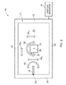
- Figs. 1 and 2 illustrate vibratory finishing apparatus 10 including a receptacle 12, at least one vibration generator 14, a fixture 16 and a guide 18.
- the vibratory finishing apparatus 10 may be a module.
- the wording 'module' refers to a device or apparatus where one or more features are included at a later time, and possibly, by another manufacturer or by an end user.
- the vibratory finishing apparatus 10 may only include the receptacle 12, the fixture 16 and the guide 18, and the remaining features (such as the vibration generator 14) may be added by another manufacturer, or by an end user.
- the receptacle 12 may have any suitable shape and may have any suitable dimensions.
- the receptacle 12 may have a bowl shape or a trough shape.
- the receptacle 12 includes side walls 22 and a base 24 that define a cavity 26 for receiving and containing the abrasive media 20.
- the abrasive media 20 may comprise any suitable abrasive media and may comprise ceramic particles and/or metal particles.
- the one or more vibration generators (such as one or more motors 14 for driving rotating shafts with eccentric weights) are arranged to vibrate the receptacle 12 and thereby cause movement of the abrasive media 20 relative to the receptacle 12.
- the one or more vibration generators 14 may be positioned at any suitable location, and may be positioned underneath the receptacle 12 (in other words, the one or more vibration generators 14 may be positioned adjacent the base 24 of the receptacle 12) or to the side of the receptacle 12.
- the fixture 16 is arranged to support an object 28 within the receptacle 12.
- the fixture 16 may extend into the cavity 26 defined by the receptacle 12 or may be positioned outside and above the cavity 26. Furthermore, the fixture 16 may partially or wholly immerse the object 28 within the abrasive media 20.
- the fixture 16 may include a first fastener 32 for fastening the fixture 16 to the receptacle 12 or for fastening the fixture 16 to another body (which may or may not be part of the vibratory finishing apparatus 10).
- the fixture 16 may also include a second fastener 34 for fastening the fixture 16 to the object 28.
- the fixture 16 is arranged to move the object 28 relative to the receptacle 12 in at least a first direction 30.
- the fixture 16 may have a longitudinal axis 36 that is parallel to the side walls 22 and perpendicular to the base 24 of the receptacle 12.
- the fixture 16 may be arranged to rotate (that is, roll) about the longitudinal axis 36 in a clockwise direction 30 and in an anti-clockwise direction 30 to rotate the object 28 relative to the receptacle 12 (that is, rotation in the azimuthal direction where the longitudinal axis 36 is the longitudinal axis of a cylindrical coordinate system).
- the fixture 16 may be additionally or alternatively arranged to rotate (as indicated by arrow 30 1 ) to change the pitch of the object 28 relative to the receptacle 12. In further examples, the fixture 16 may additionally or alternatively be arranged to move laterally (as indicated by arrows 30 2 , 30 3 and 30 4 ) relative to the receptacle 12.
- the object 28 may be any product, apparatus, device, part or component.
- the object 28 may include a fan blade root or a nozzle guide vane of a gas turbine engine.
- the object 28 may be a component manufactured by three dimensional additive manufacturing.
- the guide 18 is arranged to move relative to the receptacle 12 to direct movement of the media 20 within the receptacle 12 to a predetermined part 37 of the object 28.
- the guide 18 may be configured to be static (or at least not rotate) relative to the receptacle 12 while directing movement of the media within the receptacle to the predetermined part 37.
- the guide 18 may be rotated to an orientation to direct the movement of the media 20 within the receptacle 12 to a tarnish layer on a fan blade root and a shear key slot on a fan blade of a gas turbine engine.
- the guide 18 may be connected to the receptacle 12 (for example, one of the side walls 22 as illustrated in Figs. 1 and 2 ) and arranged to rotate about an axis 38 that is parallel to the side walls 22 (as indicated by arrow 40) (that is, rotation in the azimuthal direction where the axis 38 is the longitudinal axis of a cylindrical coordinate system).
- the guide 18 may additionally or alternatively be moved laterally relative to the receptacle 12 as indicated by arrows 40 1 and 40 2 .
- the fixture 16 may be moved so that the predetermined part 37 faces the guide 18. Then, the guide 18 may be moved so that the guide 18 is oriented towards the predetermined part 37 and so that abrasive media 20 is directed towards the predetermined part 37 by the guide 18. It should be appreciated that in other examples, the guide 18 may first be moved into a desired position, and the fixture 16 may then be moved so that the predetermined part 37 is treated by the abrasive media 20.
- the vibratory finishing apparatus 10 may provide several advantages. First, the fixture 16 and the guide 18 may be moved so that abrasive media 20 is directed towards, and rubs against, a predetermined part of the object 28. This may advantageously enable the vibratory finishing apparatus 10 to treat areas on the object 28 where conventional techniques (such as shot peening) are unable to access. Second, the fixture 16 and the guide 18 may be relatively low cost and may be used with an existing receptacle 12 (in other words, the fixture 16 and the guide 18 may be used with existing 'off the shelf' receptacles). Third, the fixture 16 and the guide 18 may be moved manually by hand and consequently, no robotics or programming skill may be required to operate the vibratory finishing apparatus 10. Fourth, since the fixture 16 and the guide 18 are adjustable, the vibratory finishing apparatus 10 may be set up for treating various surface areas of various different objects 28 (for example, objects 28 having different shapes and sizes).
- Fig. 3 illustrates a schematic cross sectional side view of another vibratory finishing apparatus 101 according to various examples.
- the vibratory finishing apparatus 101 is similar to the vibratory finishing apparatus 10 and where the features are similar, the same reference numerals are used.
- the vibratory finishing apparatus 101 includes a receptacle 12, at least one vibration generator 14, a first fixture 16, a first guide 18, a second fixture 42, a divider 44, and a second guide 46.
- the first fixture 16 and the first guide 18 are arranged as described in the preceding paragraphs with reference to Figs. 1 and 2 to enable the object 28 to be treated by the abrasive media 20.
- the second fixture 42 is arranged to support an object 48 within the receptacle 12.
- the second fixture 42 may extend into the cavity 26 defined by the receptacle 12 or may be positioned outside and above the cavity 26. Furthermore, the second fixture 42 may partially or wholly immerse the object 48 within the abrasive media 50.
- the second fixture 42 may include a first fastener 52 for fastening the second fixture 42 to the receptacle 12 or for fastening the second fixture 42 to another body (which may or may not be part of the vibratory finishing apparatus 101).
- the second fixture 42 may also include a second fastener 54 for fastening the second fixture 42 to the object 48.
- the second fixture 42 is arranged to move the object 48 relative to the receptacle 12 in at least the first direction 55.
- the second fixture 42 may have a longitudinal axis 56 that is parallel to the side walls 22 and perpendicular to the base 24 of the receptacle 12.
- the second fixture 42 may be arranged to rotate about the longitudinal axis 56 in a clockwise direction 30 and in an anti-clockwise direction 30 to rotate the object 48 relative to the receptacle 12.
- the second fixture 42 may be arranged to move laterally relative to the receptacle 12 (arrows are not illustrated in Fig. 3 to maintain the clarity of the Figure).
- the object 48 may be any product, apparatus, device, part or component.
- the object 48 may include a fan blade root or a nozzle guide vane of a gas turbine engine.
- the object 48 may be a component manufactured by three dimensional additive manufacturing.
- the object 48 may be the same type of object as the object 28, or may be a different type of object (for example, the object 28 may be a fan blade root, and the object 48 may be a nozzle guide vane).
- the divider 44 is positioned within the cavity 26 defined by the receptacle 12 and between the first fixture 16 and the second fixture 42.
- the divider 44 may be sized and shaped so that it fits snugly within the cavity 26 and abuts the side walls 22 and the base 24 of the receptacle 12.
- the divider 44 may therefore be arranged to separate the abrasive media 20 and the abrasive media 50 from one another so that there is little to no flow of the abrasive media 20 into the abrasive media 50, and similarly, so that there is little to no flow of the abrasive media 50 into the abrasive media 20.
- the divider 44 may be separate from the receptacle 12 and may be inserted into, and removed from, the receptacle 12.
- the divider 44 may include one or more fasteners for coupling the divider 44 to the receptacle 12 (or to another body, which may or may not be part of the vibratory finishing apparatus 101).
- the divider 44 may be integral with the receptacle 12 and may not be removable from the receptacle 12 (for example, the divider 44 and the receptacle 12 may be coupled to one another at a welded or brazed joint).
- the abrasive media 50 may be any suitable media and may, for example, include ceramic particles and/or metal particles.
- the abrasive media 50 may comprise the same media as the abrasive media 20, or may comprise a different media to the abrasive media 20.
- the second guide 46 is coupled to the divider 44 and is arranged to extend towards the second fixture 42 (and therefore into the media 50).
- the second guide 46 is arranged to move about an axis 60 (as indicated by arrow 62) and move relative to the receptacle 12 and to the divider 44 to direct movement of the media 50 within the receptacle 12 to a predetermined part 58 of the object 48.
- the second guide 46 may be configured to be static (or at least not rotate) relative to the receptacle 12 while directing movement of the media within the receptacle 12 to the predetermined part 58 of the further object 48.
- the second guide 46 may be rotated to direct the movement of the media 50 within the receptacle 12 to milling marks on a nozzle guide vane or milling marks on a runner casting.
- the second guide 46 may be connected to the receptacle 12 (for example, one of the side walls 22 that contains the abrasive media 50).
- the second guide 46 may additionally or alternatively be arranged to move laterally relative to the receptacle 12 (arrows are not illustrated in Fig. 3 to maintain the clarity of the Figure).
- the first and second fixtures 16, 42 may be moved so that the predetermined parts 37, 58 face the first and second guides 18, 46 respectively. Then, the first and second guides 18, 46 may be moved so that the first and second guides 18, 46 are oriented towards the predetermined parts 37, 58 respectively, and so that abrasive media 20, 50 is directed towards the predetermined parts 37, 58 by the first and second guides 18, 46 respectively. In other examples, the first and second guides 18, 46 may first be moved, and then the first and second fixtures 16, 42 may be moved. Consequently, the vibratory finishing apparatus 101 may advantageously enable a plurality of objects to be treated simultaneously and thereby enable the treatment of a greater number of objects within a given time period.
- a vibratory finishing apparatus may comprise any number of dividers, fixtures and guides for treating any number of objects within a receptacle.
- FIG. 4 illustrates a perspective view of a further vibratory finishing apparatus 102 according to various examples.
- the vibratory finishing apparatus 102 is similar to the vibratory finishing apparatus 10 and 101 and where the features are similar, the same reference numerals are used.
- the receptacle 12 has a trough shape with a first side wall 22 1 , a second side wall 22 2 , a third side wall 22 3 and a fourth side wall 22 4 .
- the first and third side walls 22 1 , 22 3 are opposite one another and the second and fourth side walls 22 2 , 22 4 are opposite one another.
- the first and third side walls 22 1 , 22 3 are longer than the second and fourth side walls 22 2 , 22 4 (which are opposite one another).
- the vibratory finishing apparatus 102 differs from the vibratory finishing apparatus 101 in that the vibratory finishing apparatus 102 includes a first divider 44 and a second divider 64 positioned within the cavity 26 of the receptacle 12.
- the fixture 16 is positioned between the first divider 44 and the second divider 64 so that the object 28 is located between the first and second dividers 44, 64 and the first and third side walls 22 1 , 22 3 .
- the guide 18 is coupled to the first divider 44 and may extend towards the fixture 16 and the object 28.
- the first divider 44 includes a U shaped frame 66 that is arranged to extend across the first and third side walls 22 1 , 22 3 to support the first divider 44 in the receptacle 12.
- the second divider 44 includes a U shaped frame 66 that is arranged to extend across the first and third side walls 22 1 , 22 3 to support the second divider 64 in the receptacle 12.
- the U shaped frames 66 of the first and second dividers 44, 64 may be fastened to the first and third side walls 22 1 , 22 3 of the receptacle 12 via one or more fasteners (such as one or more screws, bolts and so on).
- the fixture 16 includes a U shaped frame 68 that is arranged to extend across the first and third side walls 22 1 , 22 3 to support the fixture 16 in the receptacle 12.
- the U shaped frame 68 of the fixture 16 may be fastened to the first and third side walls 22 1 , 22 3 of the receptacle 12 via one or more fasteners (such as one or more screws, bolts and so on).
- the fixture 16 may also include a handle 70 for enabling a user to rotate the fixture 16 in the first direction 30.
- Figure 5 illustrates a perspective view of the fixture 16 of the vibratory finishing apparatus 102 illustrated in Fig. 4 .
- the fixture 16 includes a first part 72 and a second part 74.
- the first part 72 is coupled to the frame 68 via a joint 76 that enables the first part 72 to rotate relative to the frame 68 in the first direction 30.
- the joint 76 includes a U shaped channel 78 defined in the frame 68, and a bolt and nut arrangement 80 that extend from the first part 72 and through the channel 78 and are arranged to move within the channel 78 to enable the first part 72 to roll relative to the frame 68.
- the handle 70 has been removed from the fixture 16 illustrated in Fig. 5 in order to enable the bolt and nut arrangement 80 to be viewed.
- Figure 6 illustrates another perspective view of the fixture 16 illustrated in Figures 4 and 5 .
- the first part 72 and the second part 74 are coupled to one another via a joint 82 that enables the second part 74 to rotate relative to the first part 72 in a second direction, different to the first direction 30 (indicated by arrow 84).
- the joint 82 includes two channels 83 and a nut and bolt arrangement that extends through the two channels 83 and is moveable within the two channels 83.
- the object 28 is coupled to the second part 74 via a nut and bolt arrangement 86. Movement of the second part 74 relative to the first part 72 in the second direction 84 changes the pitch of the second part 74 (and therefore the object 28) relative to the first part 72. Consequently, the joint 76 may be considered to enable the fixture 16 to roll, and the joint 82 may be considered to enable the fixture 16 to pitch.
- the first direction 30 is the azimuthal direction and the second direction 84 is the polar direction.
- FIG. 7 illustrates a perspective view of the divider 44 and the guide 18 of the vibratory finishing apparatus 102 illustrated in Fig. 4 .
- the guide 18 includes a frame 88 that is coupled to the divider 44 (for example, via a plurality of screws) and a guider 90 that is coupled to the frame 88 at a joint 92 that enables the guider 90 to rotate in the direction 40 relative to the frame 88.
- the guider 90 includes a plate for directing the flow of abrasive media within the receptacle 12.
- the plate of the guider 90 may be planar or non-planar (for example, the plate of the guider 90 may have a curved profile).
- the joint 92 may be formed by two channels in the frame 88 and nut, and bolt arrangements extending from the guider 90 that are moveable within the two channels.
- the vibratory finishing apparatus 102 illustrated in Figs. 4 to 7 may provide several advantages.
- First, the use of the first divider 44 and the second divider 64 may enable the quantity of abrasive media used to treat the object 28 to be reduced (since the volume defined between the first and second dividers 44, 64 is less than the volume defined by the receptacle 12, or the volume between a single divider and the receptacle 12).
- Second, the ability to rotate the fixture 16 in two different directions 30, 84 and rotate the guide 18 in one direction 40 may enable abrasive media within the receptacle 12 to access parts of the object 28 that are challenging or impossible to access using conventional techniques such as shot peening.
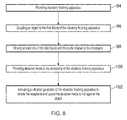
- Figure 8 illustrates a flow diagram of a method of treating an object according to various examples.
- the method includes providing vibratory finishing apparatus 10, 101, 102.
- the method includes coupling an object 28 to the first fixture 16 of the vibratory finishing apparatus 10, 101, 102.
- the method may include coupling a plurality of objects to the plurality of fixtures.
- the method includes moving at least one of the first fixture 16 and the first guide 18 relative to the receptacle 12.
- the method includes providing abrasive media 20 to the receptacle 12 of the vibratory finishing apparatus 10, 10, 102 (that is, the abrasive media 20 is poured into the cavity 26 defined by the receptacle 12).
- the method includes activating the vibration generator 14 of the vibratory finishing apparatus 10, 101, 102 to vibrate the receptacle 12 and cause the abrasive media 20 to rub against the object 28.
- blocks 94, 96, 98, 100, 102 may be performed in a different order to that illustrated in Fig. 8 .
- block 98 may be performed prior to block 96.
- block 98 may be performed prior to, and subsequent to, block 96.
Landscapes
- Engineering & Computer Science (AREA)
- Mechanical Engineering (AREA)
- Finish Polishing, Edge Sharpening, And Grinding By Specific Grinding Devices (AREA)
Abstract
Description
- The present disclosure concerns vibratory finishing apparatus, fixtures and methods of treating objects.
- Vibratory finishing apparatus usually include a receptacle filled with abrasive media, and motors for vibrating the receptacle and thereby moving the abrasive media within the receptacle. For example, the vibratory finishing apparatus may include a bowl vibrator or a trough vibrator having a vibration generator (such as one or more motors located at the bottom or side of the receptacle for driving rotating shafts with eccentric weights).
- In operation, an object to be treated (such as a fan blade of a gas turbine engine) is placed within the receptacle so that it is at least partly immersed within the abrasive media. For example, only the root of a fan blade may be immersed within the abrasive media. The receptacle is then vibrated by the motor so that the abrasive media moves within the receptacle and rubs against the object and removes a surface layer of material from the object.
- According to various, but not necessarily all, embodiments there is provided vibratory finishing apparatus comprising: a receptacle to receive abrasive media; a first fixture to: support an object within the receptacle; and move the object relative to the receptacle in at least a first direction; and a first guide to move relative to the receptacle to direct movement of the media within the receptacle to a predetermined part of the object.
- The first fixture may be arranged to move the object relative to the receptacle in at least the first direction by rotating the object. The first guide may be arranged to move relative to the receptacle by rotating relative to the receptacle.
- The first fixture may be arranged to move the object relative to the receptacle in a second direction, different to the first direction.
- The first fixture may be arranged to move the object relative to the receptacle in the second direction by rotating the object.
- The first fixture may comprise a first fastener to fasten the first fixture to the receptacle.
- The first fixture may comprise a second fastener to fasten the object to the first fixture.
- The Vibratory finishing apparatus may further comprise a first divider to be positioned within the receptacle. The first divider may comprise a fastener to fasten the first divider to the receptacle.
- The first guide may be connected at least to the first divider and may be arranged to rotate relative to the first divider.
- The first guide may be connected to the receptacle.
- The first guide may be configured to be static relative to the receptacle while directing movement of the media within the receptacle to the predetermined part of the object. The first guide may be configured to not rotate relative to the receptacle while directing movement of the media within the receptacle to the predetermined part of the object.
- The vibratory finishing apparatus may further comprise: a second fixture to: support a further object within the receptacle; and move the further object relative to the receptacle in at least a first direction; and a second guide to move relative to the receptacle to direct movement of the media within the receptacle to a predetermined part of the further object.
- The second guide may be configured to be static relative to the receptacle while directing movement of the media within the receptacle to the predetermined part of the further object. The second guide may be configured to not rotate relative to the receptacle while directing movement of the media within the receptacle to the predetermined part of the further object.
- The object may comprise a fan blade root, or a nozzle guide vane, or a component manufactured by three dimensional additive manufacturing.
- According to various, but not necessarily all, embodiments of the invention there is provided a fixture comprising: a first fastener to fasten the fixture to a receptacle of a vibratory finishing apparatus; a second fastener to fasten an object to the fixture; and a first joint to enable the object to be moved relative to the receptacle in at least a first direction.
- The fixture may further comprise a second joint to enable the object to be moved relative to the receptacle in a second direction, different to the first direction.
- According to various, but not necessarily all, embodiments of the invention there is provided a method of treating an object, the method comprising: providing vibratory finishing apparatus as described in any of the preceding paragraphs; coupling an object to the first fixture of the vibratory finishing apparatus; moving at least one of the first fixture and the first guide relative to the receptacle; providing abrasive media to the receptacle of the vibratory finishing apparatus; and activating a vibration generator of the vibratory finishing apparatus to vibrate the receptacle and cause the abrasive media to rub against the object.
- The skilled person will appreciate that except where mutually exclusive, a feature described in relation to any one of the above aspects may be applied mutatis mutandis to any other aspect. Furthermore except where mutually exclusive any feature described herein may be applied to any aspect and/or combined with any other feature described herein.
- Embodiments will now be described by way of example only, with reference to the Figures, in which:
-
Figure 1 illustrates a schematic cross sectional side view of vibratory finishing apparatus according to various examples; -
Figure 2 illustrates a schematic plan view of the vibratory finishing apparatus illustrated inFigure 1 ; -
Figure 3 illustrates a schematic cross sectional side view of another vibratory finishing apparatus according to various examples; -
Figure 4 illustrates a perspective view of a further vibratory finishing apparatus according to various examples; -
Figure 5 illustrates a perspective view of the fixture of the vibratory finishing apparatus illustrated inFig. 4 ; -
Figure 6 illustrates another perspective view of the fixture illustrated inFigures 4 and5 ; -
Figure 7 illustrates a perspective view of the divider and the guide of the vibratory finishing apparatus illustrated inFig. 4 ; and -
Figure 8 illustrates a flow diagram of a method of treating an object according to various examples. - In the following description, the terms 'connected' and 'coupled' mean operationally connected and coupled. It should be appreciated that there may be any number of intervening components between the mentioned features, including no intervening components.
- In more detail,
Figs. 1 and2 illustratevibratory finishing apparatus 10 including areceptacle 12, at least onevibration generator 14, afixture 16 and aguide 18. In some examples, thevibratory finishing apparatus 10 may be a module. As used herein, the wording 'module' refers to a device or apparatus where one or more features are included at a later time, and possibly, by another manufacturer or by an end user. For example, where thevibratory finishing apparatus 10 is a module, thevibratory finishing apparatus 10 may only include thereceptacle 12, thefixture 16 and theguide 18, and the remaining features (such as the vibration generator 14) may be added by another manufacturer, or by an end user. - The
receptacle 12 may have any suitable shape and may have any suitable dimensions. For example, thereceptacle 12 may have a bowl shape or a trough shape. Thereceptacle 12 includesside walls 22 and abase 24 that define acavity 26 for receiving and containing theabrasive media 20. Theabrasive media 20 may comprise any suitable abrasive media and may comprise ceramic particles and/or metal particles. - The one or more vibration generators (such as one or
more motors 14 for driving rotating shafts with eccentric weights) are arranged to vibrate thereceptacle 12 and thereby cause movement of theabrasive media 20 relative to thereceptacle 12. The one ormore vibration generators 14 may be positioned at any suitable location, and may be positioned underneath the receptacle 12 (in other words, the one ormore vibration generators 14 may be positioned adjacent thebase 24 of the receptacle 12) or to the side of thereceptacle 12. - The
fixture 16 is arranged to support anobject 28 within thereceptacle 12. Thefixture 16 may extend into thecavity 26 defined by thereceptacle 12 or may be positioned outside and above thecavity 26. Furthermore, thefixture 16 may partially or wholly immerse theobject 28 within theabrasive media 20. Thefixture 16 may include afirst fastener 32 for fastening thefixture 16 to thereceptacle 12 or for fastening thefixture 16 to another body (which may or may not be part of the vibratory finishing apparatus 10). Thefixture 16 may also include asecond fastener 34 for fastening thefixture 16 to theobject 28. - The
fixture 16 is arranged to move theobject 28 relative to thereceptacle 12 in at least afirst direction 30. For example, thefixture 16 may have alongitudinal axis 36 that is parallel to theside walls 22 and perpendicular to thebase 24 of thereceptacle 12. Thefixture 16 may be arranged to rotate (that is, roll) about thelongitudinal axis 36 in aclockwise direction 30 and in ananti-clockwise direction 30 to rotate theobject 28 relative to the receptacle 12 (that is, rotation in the azimuthal direction where thelongitudinal axis 36 is the longitudinal axis of a cylindrical coordinate system). In other examples, thefixture 16 may be additionally or alternatively arranged to rotate (as indicated by arrow 301) to change the pitch of theobject 28 relative to thereceptacle 12. In further examples, thefixture 16 may additionally or alternatively be arranged to move laterally (as indicated byarrows receptacle 12. - It should be appreciated that the
object 28 may be any product, apparatus, device, part or component. For example, theobject 28 may include a fan blade root or a nozzle guide vane of a gas turbine engine. By way of another example, theobject 28 may be a component manufactured by three dimensional additive manufacturing. - The
guide 18 is arranged to move relative to thereceptacle 12 to direct movement of themedia 20 within thereceptacle 12 to apredetermined part 37 of theobject 28. In more detail, theguide 18 may be configured to be static (or at least not rotate) relative to thereceptacle 12 while directing movement of the media within the receptacle to thepredetermined part 37. - For example, the
guide 18 may be rotated to an orientation to direct the movement of themedia 20 within thereceptacle 12 to a tarnish layer on a fan blade root and a shear key slot on a fan blade of a gas turbine engine. Theguide 18 may be connected to the receptacle 12 (for example, one of theside walls 22 as illustrated inFigs. 1 and2 ) and arranged to rotate about anaxis 38 that is parallel to the side walls 22 (as indicated by arrow 40) (that is, rotation in the azimuthal direction where theaxis 38 is the longitudinal axis of a cylindrical coordinate system). In other examples, theguide 18 may additionally or alternatively be moved laterally relative to thereceptacle 12 as indicated byarrows - Where it is desired to treat a predetermined part (such as part 37) of the
object 28, thefixture 16 may be moved so that thepredetermined part 37 faces theguide 18. Then, theguide 18 may be moved so that theguide 18 is oriented towards thepredetermined part 37 and so thatabrasive media 20 is directed towards thepredetermined part 37 by theguide 18. It should be appreciated that in other examples, theguide 18 may first be moved into a desired position, and thefixture 16 may then be moved so that thepredetermined part 37 is treated by theabrasive media 20. - The
vibratory finishing apparatus 10 may provide several advantages. First, thefixture 16 and theguide 18 may be moved so thatabrasive media 20 is directed towards, and rubs against, a predetermined part of theobject 28. This may advantageously enable thevibratory finishing apparatus 10 to treat areas on theobject 28 where conventional techniques (such as shot peening) are unable to access. Second, thefixture 16 and theguide 18 may be relatively low cost and may be used with an existing receptacle 12 (in other words, thefixture 16 and theguide 18 may be used with existing 'off the shelf' receptacles). Third, thefixture 16 and theguide 18 may be moved manually by hand and consequently, no robotics or programming skill may be required to operate thevibratory finishing apparatus 10. Fourth, since thefixture 16 and theguide 18 are adjustable, thevibratory finishing apparatus 10 may be set up for treating various surface areas of various different objects 28 (for example, objects 28 having different shapes and sizes). -
Fig. 3 illustrates a schematic cross sectional side view of anothervibratory finishing apparatus 101 according to various examples. Thevibratory finishing apparatus 101 is similar to thevibratory finishing apparatus 10 and where the features are similar, the same reference numerals are used. Thevibratory finishing apparatus 101 includes areceptacle 12, at least onevibration generator 14, afirst fixture 16, afirst guide 18, asecond fixture 42, adivider 44, and asecond guide 46. - The
first fixture 16 and thefirst guide 18 are arranged as described in the preceding paragraphs with reference toFigs. 1 and2 to enable theobject 28 to be treated by theabrasive media 20. - The
second fixture 42 is arranged to support anobject 48 within thereceptacle 12. Thesecond fixture 42 may extend into thecavity 26 defined by thereceptacle 12 or may be positioned outside and above thecavity 26. Furthermore, thesecond fixture 42 may partially or wholly immerse theobject 48 within theabrasive media 50. Thesecond fixture 42 may include afirst fastener 52 for fastening thesecond fixture 42 to thereceptacle 12 or for fastening thesecond fixture 42 to another body (which may or may not be part of the vibratory finishing apparatus 101). Thesecond fixture 42 may also include asecond fastener 54 for fastening thesecond fixture 42 to theobject 48. - The
second fixture 42 is arranged to move theobject 48 relative to thereceptacle 12 in at least thefirst direction 55. For example, thesecond fixture 42 may have alongitudinal axis 56 that is parallel to theside walls 22 and perpendicular to thebase 24 of thereceptacle 12. Thesecond fixture 42 may be arranged to rotate about thelongitudinal axis 56 in aclockwise direction 30 and in ananti-clockwise direction 30 to rotate theobject 48 relative to thereceptacle 12. Additionally or alternatively, thesecond fixture 42 may be arranged to move laterally relative to the receptacle 12 (arrows are not illustrated inFig. 3 to maintain the clarity of the Figure). - The
object 48 may be any product, apparatus, device, part or component. For example, theobject 48 may include a fan blade root or a nozzle guide vane of a gas turbine engine. By way of another example, theobject 48 may be a component manufactured by three dimensional additive manufacturing. Theobject 48 may be the same type of object as theobject 28, or may be a different type of object (for example, theobject 28 may be a fan blade root, and theobject 48 may be a nozzle guide vane). - The
divider 44 is positioned within thecavity 26 defined by thereceptacle 12 and between thefirst fixture 16 and thesecond fixture 42. Thedivider 44 may be sized and shaped so that it fits snugly within thecavity 26 and abuts theside walls 22 and thebase 24 of thereceptacle 12. Thedivider 44 may therefore be arranged to separate theabrasive media 20 and theabrasive media 50 from one another so that there is little to no flow of theabrasive media 20 into theabrasive media 50, and similarly, so that there is little to no flow of theabrasive media 50 into theabrasive media 20. - The
divider 44 may be separate from thereceptacle 12 and may be inserted into, and removed from, thereceptacle 12. Thedivider 44 may include one or more fasteners for coupling thedivider 44 to the receptacle 12 (or to another body, which may or may not be part of the vibratory finishing apparatus 101). In other examples, thedivider 44 may be integral with thereceptacle 12 and may not be removable from the receptacle 12 (for example, thedivider 44 and thereceptacle 12 may be coupled to one another at a welded or brazed joint). - The
abrasive media 50 may be any suitable media and may, for example, include ceramic particles and/or metal particles. Theabrasive media 50 may comprise the same media as theabrasive media 20, or may comprise a different media to theabrasive media 20. - The
second guide 46 is coupled to thedivider 44 and is arranged to extend towards the second fixture 42 (and therefore into the media 50). Thesecond guide 46 is arranged to move about an axis 60 (as indicated by arrow 62) and move relative to thereceptacle 12 and to thedivider 44 to direct movement of themedia 50 within thereceptacle 12 to apredetermined part 58 of theobject 48. In more detail, thesecond guide 46 may be configured to be static (or at least not rotate) relative to thereceptacle 12 while directing movement of the media within thereceptacle 12 to thepredetermined part 58 of thefurther object 48. - For example, the
second guide 46 may be rotated to direct the movement of themedia 50 within thereceptacle 12 to milling marks on a nozzle guide vane or milling marks on a runner casting. In other examples, thesecond guide 46 may be connected to the receptacle 12 (for example, one of theside walls 22 that contains the abrasive media 50). In some examples, thesecond guide 46 may additionally or alternatively be arranged to move laterally relative to the receptacle 12 (arrows are not illustrated inFig. 3 to maintain the clarity of the Figure). - Where it is desired to treat predetermined parts (such as
parts 37 and 58) of theobjects second fixtures predetermined parts second guides second guides second guides predetermined parts abrasive media predetermined parts second guides second guides second fixtures vibratory finishing apparatus 101 may advantageously enable a plurality of objects to be treated simultaneously and thereby enable the treatment of a greater number of objects within a given time period. - It should be appreciated that in other examples, a vibratory finishing apparatus may comprise any number of dividers, fixtures and guides for treating any number of objects within a receptacle.
-
Figure 4 illustrates a perspective view of a furthervibratory finishing apparatus 102 according to various examples. Thevibratory finishing apparatus 102 is similar to thevibratory finishing apparatus - In this example, the
receptacle 12 has a trough shape with afirst side wall 221, asecond side wall 222, athird side wall 223 and afourth side wall 224. The first andthird side walls fourth side walls third side walls fourth side walls 222, 224 (which are opposite one another). - The
vibratory finishing apparatus 102 differs from thevibratory finishing apparatus 101 in that thevibratory finishing apparatus 102 includes afirst divider 44 and asecond divider 64 positioned within thecavity 26 of thereceptacle 12. Thefixture 16 is positioned between thefirst divider 44 and thesecond divider 64 so that theobject 28 is located between the first andsecond dividers third side walls guide 18 is coupled to thefirst divider 44 and may extend towards thefixture 16 and theobject 28. - The
first divider 44 includes a U shapedframe 66 that is arranged to extend across the first andthird side walls first divider 44 in thereceptacle 12. Similarly, thesecond divider 44 includes a U shapedframe 66 that is arranged to extend across the first andthird side walls second divider 64 in thereceptacle 12. The U shaped frames 66 of the first andsecond dividers third side walls receptacle 12 via one or more fasteners (such as one or more screws, bolts and so on). - The
fixture 16 includes a U shapedframe 68 that is arranged to extend across the first andthird side walls fixture 16 in thereceptacle 12. The U shapedframe 68 of thefixture 16 may be fastened to the first andthird side walls receptacle 12 via one or more fasteners (such as one or more screws, bolts and so on). Thefixture 16 may also include ahandle 70 for enabling a user to rotate thefixture 16 in thefirst direction 30. -
Figure 5 illustrates a perspective view of thefixture 16 of thevibratory finishing apparatus 102 illustrated inFig. 4 . Thefixture 16 includes afirst part 72 and asecond part 74. Thefirst part 72 is coupled to theframe 68 via a joint 76 that enables thefirst part 72 to rotate relative to theframe 68 in thefirst direction 30.
In this example, the joint 76 includes a U shapedchannel 78 defined in theframe 68, and a bolt andnut arrangement 80 that extend from thefirst part 72 and through thechannel 78 and are arranged to move within thechannel 78 to enable thefirst part 72 to roll relative to theframe 68. It should be appreciated that thehandle 70 has been removed from thefixture 16 illustrated inFig. 5 in order to enable the bolt andnut arrangement 80 to be viewed. -
Figure 6 illustrates another perspective view of thefixture 16 illustrated inFigures 4 and5 . Thefirst part 72 and thesecond part 74 are coupled to one another via a joint 82 that enables thesecond part 74 to rotate relative to thefirst part 72 in a second direction, different to the first direction 30 (indicated by arrow 84). The joint 82 includes twochannels 83 and a nut and bolt arrangement that extends through the twochannels 83 and is moveable within the twochannels 83. - The
object 28 is coupled to thesecond part 74 via a nut andbolt arrangement 86. Movement of thesecond part 74 relative to thefirst part 72 in thesecond direction 84 changes the pitch of the second part 74 (and therefore the object 28) relative to thefirst part 72. Consequently, the joint 76 may be considered to enable thefixture 16 to roll, and the joint 82 may be considered to enable thefixture 16 to pitch. In other words, where the point of coupling between thefirst part 72 and theframe 68 is considered to be the centre of a spherical coordinate system, thefirst direction 30 is the azimuthal direction and thesecond direction 84 is the polar direction. -
Figure 7 illustrates a perspective view of thedivider 44 and theguide 18 of thevibratory finishing apparatus 102 illustrated inFig. 4 . Theguide 18 includes aframe 88 that is coupled to the divider 44 (for example, via a plurality of screws) and aguider 90 that is coupled to theframe 88 at a joint 92 that enables theguider 90 to rotate in thedirection 40 relative to theframe 88. Theguider 90 includes a plate for directing the flow of abrasive media within thereceptacle 12. The plate of theguider 90 may be planar or non-planar (for example, the plate of theguider 90 may have a curved profile). The joint 92 may be formed by two channels in theframe 88 and nut, and bolt arrangements extending from theguider 90 that are moveable within the two channels. - The
vibratory finishing apparatus 102 illustrated inFigs. 4 to 7 may provide several advantages. First, the use of thefirst divider 44 and thesecond divider 64 may enable the quantity of abrasive media used to treat theobject 28 to be reduced (since the volume defined between the first andsecond dividers receptacle 12, or the volume between a single divider and the receptacle 12). Second, the ability to rotate thefixture 16 in twodifferent directions guide 18 in onedirection 40 may enable abrasive media within thereceptacle 12 to access parts of theobject 28 that are challenging or impossible to access using conventional techniques such as shot peening. -
Figure 8 illustrates a flow diagram of a method of treating an object according to various examples. - At
block 94, the method includes providingvibratory finishing apparatus - At
block 96, the method includes coupling anobject 28 to thefirst fixture 16 of thevibratory finishing apparatus vibratory finishing apparatus - At
block 98, the method includes moving at least one of thefirst fixture 16 and thefirst guide 18 relative to thereceptacle 12. - At
block 100, the method includes providingabrasive media 20 to thereceptacle 12 of thevibratory finishing apparatus abrasive media 20 is poured into thecavity 26 defined by the receptacle 12). - At
block 102, the method includes activating thevibration generator 14 of thevibratory finishing apparatus receptacle 12 and cause theabrasive media 20 to rub against theobject 28. - It should be appreciated that the
blocks Fig. 8 . For example, block 98 may be performed prior to block 96. In other examples, block 98 may be performed prior to, and subsequent to, block 96. - It will be understood that the disclosure is not limited to the embodiments above-described and various modifications and improvements can be made without departing from the concepts described herein.
- Except where mutually exclusive, any of the features may be employed separately or in combination with any other features and the disclosure extends to and includes all combinations and sub-combinations of one or more features described herein.
Claims (15)
- Vibratory finishing apparatus comprising:a receptacle to receive abrasive media;a first fixture to: support an object within the receptacle; and move the object relative to the receptacle in at least a first direction; anda first guide to move relative to the receptacle to direct movement of the media within the receptacle to a predetermined part of the object.
- Vibratory finishing apparatus as claimed in claim 1, wherein the first fixture is arranged to move the object relative to the receptacle in at least the first direction by rotating the object.
- Vibratory finishing apparatus as claimed in claim 1 or 2, wherein the first guide is arranged to move relative to the receptacle by rotating relative to the receptacle.
- Vibratory finishing apparatus as claimed in any of the preceding claim, wherein the first fixture is arranged to move the object relative to the receptacle in a second direction, different to the first direction.
- Vibratory finishing apparatus as claimed in claim 4, wherein the first fixture is arranged to move the object relative to the receptacle in the second direction by rotating the object.
- Vibratory finishing apparatus as claimed in any of the preceding claims, wherein the first fixture comprises a first fastener to fasten the first fixture to the receptacle.
- Vibratory finishing apparatus as claimed in any of the preceding claims, wherein the first fixture comprises a second fastener to fasten the object to the first fixture.
- Vibratory finishing apparatus as claimed in any of the preceding claims, further comprising a first divider to be positioned within the receptacle.
- Vibratory finishing apparatus as claimed in claim 8, wherein the first divider comprises a fastener to fasten the first divider to the receptacle.
- Vibratory finishing apparatus as claimed in claim 8 or 9, wherein the first guide is connected at least to the first divider and is arranged to rotate relative to the first divider.
- Vibratory finishing apparatus as claimed in any of the preceding claims, wherein the first guide is configured to be static relative to the receptacle while directing movement of the media within the receptacle to the predetermined part of the object.
- Vibratory finishing apparatus as claimed in any of the preceding claims, further comprising:a second fixture to: support a further object within the receptacle; and move the further object relative to the receptacle in at least a first direction; anda second guide to move relative to the receptacle to direct movement of the media within the receptacle to a predetermined part of the further object.
- Vibratory finishing apparatus as claimed in claim 13, wherein the second guide is configured to be static relative to the receptacle while directing movement of the media within the receptacle to the predetermined part of the further object.
- Vibratory finishing apparatus as claimed in any of the preceding claims, wherein the object comprises a fan blade root, or a nozzle guide vane, or a component manufactured by three dimensional additive manufacturing.
- A method of treating an object, the method comprising:providing vibratory finishing apparatus as claimed in any of claims 1 to 14;coupling an object to the first fixture of the vibratory finishing apparatus;moving at least one of the first fixture and the first guide relative to the receptacle;providing abrasive media to the receptacle of the vibratory finishing apparatus; andactivating a vibration generator of the vibratory finishing apparatus to vibrate the receptacle and cause the abrasive media to rub against the object.
Applications Claiming Priority (1)
| Application Number | Priority Date | Filing Date | Title |
|---|---|---|---|
| GBGB1509230.7A GB201509230D0 (en) | 2015-05-29 | 2015-05-29 | Vibratory finishing apparatus, fixtures and methods |
Publications (2)
| Publication Number | Publication Date |
|---|---|
| EP3098026A1 true EP3098026A1 (en) | 2016-11-30 |
| EP3098026B1 EP3098026B1 (en) | 2019-09-25 |
Family
ID=53677395
Family Applications (1)
| Application Number | Title | Priority Date | Filing Date |
|---|---|---|---|
| EP16168900.5A Active EP3098026B1 (en) | 2015-05-29 | 2016-05-10 | Vibratory finishing apparatus, fixtures and methods |
Country Status (3)
| Country | Link |
|---|---|
| US (1) | US10166651B2 (en) |
| EP (1) | EP3098026B1 (en) |
| GB (1) | GB201509230D0 (en) |
Cited By (3)
| Publication number | Priority date | Publication date | Assignee | Title |
|---|---|---|---|---|
| CN110434680A (en) * | 2019-07-19 | 2019-11-12 | 大连理工大学 | A kind of chemical mechanical polishing liquid and polishing method of propeller |
| IT201800009904A1 (en) * | 2018-10-30 | 2020-04-30 | Rösler Italiana Srl | Support, machine and process for surface finishes |
| CN112077675A (en) * | 2020-09-17 | 2020-12-15 | 中国航发沈阳黎明航空发动机有限责任公司 | A method for improving the surface quality of the turning surface of the rectifier assembly and matching parts |
Families Citing this family (8)
| Publication number | Priority date | Publication date | Assignee | Title |
|---|---|---|---|---|
| ITFI20130248A1 (en) * | 2013-10-17 | 2015-04-18 | Nuovo Pignone Srl | "AIRFOIL MACHINE COMPONENTS POLISHING METHOD" |
| US11351605B2 (en) | 2017-05-18 | 2022-06-07 | General Electric Company | Powder packing methods and apparatus |
| US11344989B2 (en) * | 2019-02-11 | 2022-05-31 | Aref Azami Gilan | Rotational abrasive micro/nano-finishing |
| US11440097B2 (en) | 2019-02-12 | 2022-09-13 | General Electric Company | Methods for additively manufacturing components using lattice support structures |
| WO2021146453A1 (en) * | 2020-01-14 | 2021-07-22 | International Marketing, Inc. | Method of cleaning an aluminum wheel |
| CN111390658A (en) * | 2020-04-30 | 2020-07-10 | 岭南师范学院 | Micro-channel electrophoresis auxiliary micro-ultrasonic processing device and method |
| FR3121061B1 (en) | 2021-03-26 | 2023-08-04 | Safran Aircraft Engines | METHOD FOR MANUFACTURING A METAL ALLOY PART FOR A TURBOMACHINE |
| GB202203546D0 (en) * | 2022-03-15 | 2022-04-27 | Rolls Royce Plc | Component treatment method and apparatus |
Citations (5)
| Publication number | Priority date | Publication date | Assignee | Title |
|---|---|---|---|---|
| RU2030281C1 (en) * | 1991-11-04 | 1995-03-10 | Раид Минулович Халимулин | Vibration machine tool |
| US5593339A (en) * | 1993-08-12 | 1997-01-14 | Church & Dwight Co., Inc. | Slurry cleaning process |
| EP1362669A2 (en) * | 2002-05-16 | 2003-11-19 | Rösler Oberflächentechnik GmbH | Polishing process and device for polishing of rotationally symmetric workpieces |
| US20060246825A1 (en) * | 2000-12-27 | 2006-11-02 | Andrea Bolz | Method for smoothing the surface of a gas turbine blade |
| DE102013107497A1 (en) * | 2013-07-15 | 2015-01-15 | Rolls-Royce Deutschland Ltd & Co Kg | Device for non-abrasive surface treatment of a component in a container |
Family Cites Families (28)
| Publication number | Priority date | Publication date | Assignee | Title |
|---|---|---|---|---|
| US2554701A (en) * | 1947-03-04 | 1951-05-29 | Doehler Jarvis Corp | Treatment of articles to remove some of the outside material therefrom or to polish the same |
| DE1931824U (en) | 1965-11-29 | 1966-01-27 | Walther Technik Carl Kurt Walt | DEVICE FOR THE SURFACE TREATMENT OF BULK PARTS. |
| DE2919401A1 (en) | 1979-05-14 | 1981-02-26 | Roesler R S Kg | Surface grinding and polishing vibrator - has cover at trough opening bearing on material used for treatment |
| US4706414A (en) | 1985-05-28 | 1987-11-17 | Outboard Marine Corporation | Apparatus for rotatably supporting a marine propeller in a vibrating media |
| SU1407770A1 (en) | 1985-11-26 | 1988-07-07 | Ростовский-На-Дону Институт Сельскохозяйственного Машиностроения | Apparatus for vibration working of articles |
| SU1404296A1 (en) | 1986-06-03 | 1988-06-23 | Ростовский-На-Дону Институт Сельскохозяйственного Машиностроения | Apparatus for vibration machining |
| US5375377A (en) * | 1990-03-05 | 1994-12-27 | Nova Finishing Systems, Inc. | Internal tray for a vibratory mill |
| DE69102311T2 (en) * | 1990-03-07 | 1994-09-29 | Hitachi Ltd | Device and method for surface cleaning. |
| CN1035365C (en) | 1992-02-14 | 1997-07-09 | 大野家建 | Method fpr partitioning a grinding drum, and the grinding drum |
| US5460566A (en) * | 1993-02-11 | 1995-10-24 | Drilltech Technologies, Inc. | Vibrating abrasive cleaning apparatus and method |
| US5512008A (en) * | 1993-07-27 | 1996-04-30 | General Kinematics Corporation | Vibratory tumbling apparatus |
| US20010003696A1 (en) * | 1996-11-27 | 2001-06-14 | Bbf Yamate Corporation | Wet type buffing method, deposition plating method, work buffing method, work buffing apparatus, barrel buffing apparatus, work surface treating method, work supporting unit for barrel buffing apparatus, and buffing medium |
| US6688953B2 (en) * | 1996-11-27 | 2004-02-10 | Shuji Kawasaki | Barrel polishing apparatus |
| EP0922530B1 (en) * | 1997-12-10 | 2005-03-23 | Shuji Kawasaki | Barrel-polishing apparatus |
| US6261154B1 (en) * | 1998-08-25 | 2001-07-17 | Mceneny Jeffrey William | Method and apparatus for media finishing |
| US7883396B2 (en) * | 2006-08-21 | 2011-02-08 | Battenfeld Technologies, Inc. | Vibratory tumblers for processing workpieces and methods for packaging and constructing such tumblers |
| JP2009125862A (en) | 2007-11-22 | 2009-06-11 | Ee P C Aero Specialty Kk | Vibration type polishing device |
| US9550272B2 (en) * | 2009-11-17 | 2017-01-24 | Rem Technologies, Inc. | Magnetic fixture |
| JP5412258B2 (en) | 2009-12-04 | 2014-02-12 | 株式会社レイズエンジニアリング | Vibration polishing method and vibration polishing apparatus for vehicle wheel |
| IT1401855B1 (en) * | 2010-10-19 | 2013-08-28 | Mingot | EQUIPMENT FOR THE TREATMENT OF A PRODUCT. |
| SG195417A1 (en) * | 2012-06-01 | 2013-12-30 | Pratt & Whitney Services Pte Ltd | Polishing assembly and method for polishing |
| US20140065929A1 (en) * | 2012-08-30 | 2014-03-06 | John S. Davidson | High-speed mass finishing device and method |
| US9017142B2 (en) * | 2013-02-14 | 2015-04-28 | Ericus Andreas van Kleef | Mass finishing apparatus and method |
| US9610671B2 (en) * | 2013-03-12 | 2017-04-04 | United Technologies Corporation | Drag finishing system, method and fixture for gas turbine engine airfoils |
| DE102013107494A1 (en) * | 2013-07-15 | 2015-01-15 | Rolls-Royce Deutschland Ltd & Co Kg | Device and method for surface treatment of a component with a relative to a reference device movably mounted container |
| CN105451939B (en) * | 2013-08-09 | 2018-09-04 | 新东工业株式会社 | Grinding device and grinding method |
| JP6547971B2 (en) * | 2013-08-28 | 2019-07-24 | エムディーエス コーティング テクノロジーズ コーポレーションMds Coating Technologies Corp. | Airfoil covering and method of grinding airfoil |
| ITFI20130248A1 (en) * | 2013-10-17 | 2015-04-18 | Nuovo Pignone Srl | "AIRFOIL MACHINE COMPONENTS POLISHING METHOD" |
-
2015
- 2015-05-29 GB GBGB1509230.7A patent/GB201509230D0/en not_active Ceased
-
2016
- 2016-05-10 EP EP16168900.5A patent/EP3098026B1/en active Active
- 2016-05-10 US US15/151,085 patent/US10166651B2/en active Active
Patent Citations (5)
| Publication number | Priority date | Publication date | Assignee | Title |
|---|---|---|---|---|
| RU2030281C1 (en) * | 1991-11-04 | 1995-03-10 | Раид Минулович Халимулин | Vibration machine tool |
| US5593339A (en) * | 1993-08-12 | 1997-01-14 | Church & Dwight Co., Inc. | Slurry cleaning process |
| US20060246825A1 (en) * | 2000-12-27 | 2006-11-02 | Andrea Bolz | Method for smoothing the surface of a gas turbine blade |
| EP1362669A2 (en) * | 2002-05-16 | 2003-11-19 | Rösler Oberflächentechnik GmbH | Polishing process and device for polishing of rotationally symmetric workpieces |
| DE102013107497A1 (en) * | 2013-07-15 | 2015-01-15 | Rolls-Royce Deutschland Ltd & Co Kg | Device for non-abrasive surface treatment of a component in a container |
Non-Patent Citations (1)
| Title |
|---|
| UHLMANN E ET AL: "Polieren komplexer Bauteile", WERKSTATT + BETRIEB, CARL HANSER VERLAG, MÜNCHEN DE, vol. 144, no. 6, 1 June 2011 (2011-06-01), pages 28 - 31, XP001563959, ISSN: 0043-2792 * |
Cited By (5)
| Publication number | Priority date | Publication date | Assignee | Title |
|---|---|---|---|---|
| IT201800009904A1 (en) * | 2018-10-30 | 2020-04-30 | Rösler Italiana Srl | Support, machine and process for surface finishes |
| EP3646988A1 (en) * | 2018-10-30 | 2020-05-06 | Rösler Italiana S.r.l. | Support, machine and process for surface finishing |
| CN110434680A (en) * | 2019-07-19 | 2019-11-12 | 大连理工大学 | A kind of chemical mechanical polishing liquid and polishing method of propeller |
| CN112077675A (en) * | 2020-09-17 | 2020-12-15 | 中国航发沈阳黎明航空发动机有限责任公司 | A method for improving the surface quality of the turning surface of the rectifier assembly and matching parts |
| CN112077675B (en) * | 2020-09-17 | 2021-11-16 | 中国航发沈阳黎明航空发动机有限责任公司 | Method for improving surface quality of turning of assembly matching part of rectifier by polishing |
Also Published As
| Publication number | Publication date |
|---|---|
| GB201509230D0 (en) | 2015-07-15 |
| US10166651B2 (en) | 2019-01-01 |
| US20160346896A1 (en) | 2016-12-01 |
| EP3098026B1 (en) | 2019-09-25 |
Similar Documents
| Publication | Publication Date | Title |
|---|---|---|
| US10166651B2 (en) | Vibratory finishing apparatus, fixtures and method | |
| US9346139B2 (en) | Vibrating device with workpiece receiving portion and compensating mass | |
| WO2000010770A2 (en) | Method and apparatus for media finishing | |
| US12145240B2 (en) | Cavitation processing apparatus and cavitation processing method | |
| JP2019521868A (en) | Surface homogenizer | |
| CN100333877C (en) | Method and equipment for vibration grinding, polishing and deburring of metal workpiece | |
| EP3251793B1 (en) | Vibratory treatment apparatus and method of vibratory treatment | |
| CN118181121A (en) | A blade surface finishing processing device and processing method for multi-array closed cavity | |
| KR101845133B1 (en) | Vibration polishing apparatus | |
| JP2009125862A (en) | Vibration type polishing device | |
| US10406650B2 (en) | Airfoil masking tool and method of polishing an airfoil | |
| CN108621018A (en) | Pneumatic type three-dimensional force inner cavity rust remover | |
| CN107838817B (en) | Product positioning mechanism and sand blasting mechanism | |
| CN106466795B (en) | An inner hole polishing device and method | |
| KR200484722Y1 (en) | Material Turning Device for Liquid Honing | |
| RU2342243C2 (en) | Method for vibroimpact processing of thin-walled part surfaces | |
| RU63281U1 (en) | INSTALLATION FOR VIBRICULAR PROCESSING OF SURFACES OF THIN-WALLED PARTS | |
| US1141095A (en) | Sharpener for hair-clippers. | |
| WO2004078415A1 (en) | Method and device for treating the surfaces of metallic workpieces | |
| RU2333822C1 (en) | Method of combined magnetic-pulse processing of impeller machines parts and device for its implementation | |
| KR900004643B1 (en) | Grinder | |
| JP2001030064A (en) | Internal adhering matter removal method and vibration device | |
| US4559742A (en) | Machine for vibratory grinding of workpieces | |
| US4058869A (en) | Scrubbing apparatus for pottery greenware | |
| WO2015027310A1 (en) | Airfoil masking tool and method of polishing an airfoil |
Legal Events
| Date | Code | Title | Description |
|---|---|---|---|
| PUAI | Public reference made under article 153(3) epc to a published international application that has entered the european phase |
Free format text: ORIGINAL CODE: 0009012 |
|
| AK | Designated contracting states |
Kind code of ref document: A1 Designated state(s): AL AT BE BG CH CY CZ DE DK EE ES FI FR GB GR HR HU IE IS IT LI LT LU LV MC MK MT NL NO PL PT RO RS SE SI SK SM TR |
|
| AX | Request for extension of the european patent |
Extension state: BA ME |
|
| STAA | Information on the status of an ep patent application or granted ep patent |
Free format text: STATUS: REQUEST FOR EXAMINATION WAS MADE |
|
| 17P | Request for examination filed |
Effective date: 20170517 |
|
| RBV | Designated contracting states (corrected) |
Designated state(s): AL AT BE BG CH CY CZ DE DK EE ES FI FR GB GR HR HU IE IS IT LI LT LU LV MC MK MT NL NO PL PT RO RS SE SI SK SM TR |
|
| STAA | Information on the status of an ep patent application or granted ep patent |
Free format text: STATUS: EXAMINATION IS IN PROGRESS |
|
| 17Q | First examination report despatched |
Effective date: 20180925 |
|
| REG | Reference to a national code |
Ref country code: DE Ref legal event code: R079 Ref document number: 602016021112 Country of ref document: DE Free format text: PREVIOUS MAIN CLASS: B24B0031060000 Ipc: B24B0037200000 |
|
| GRAP | Despatch of communication of intention to grant a patent |
Free format text: ORIGINAL CODE: EPIDOSNIGR1 |
|
| STAA | Information on the status of an ep patent application or granted ep patent |
Free format text: STATUS: GRANT OF PATENT IS INTENDED |
|
| RIC1 | Information provided on ipc code assigned before grant |
Ipc: B24B 37/20 20120101AFI20190515BHEP Ipc: B24B 31/06 20060101ALI20190515BHEP Ipc: B24B 31/00 20060101ALI20190515BHEP |
|
| INTG | Intention to grant announced |
Effective date: 20190606 |
|
| GRAS | Grant fee paid |
Free format text: ORIGINAL CODE: EPIDOSNIGR3 |
|
| GRAA | (expected) grant |
Free format text: ORIGINAL CODE: 0009210 |
|
| STAA | Information on the status of an ep patent application or granted ep patent |
Free format text: STATUS: THE PATENT HAS BEEN GRANTED |
|
| AK | Designated contracting states |
Kind code of ref document: B1 Designated state(s): AL AT BE BG CH CY CZ DE DK EE ES FI FR GB GR HR HU IE IS IT LI LT LU LV MC MK MT NL NO PL PT RO RS SE SI SK SM TR |
|
| REG | Reference to a national code |
Ref country code: GB Ref legal event code: FG4D |
|
| REG | Reference to a national code |
Ref country code: CH Ref legal event code: EP |
|
| REG | Reference to a national code |
Ref country code: AT Ref legal event code: REF Ref document number: 1183340 Country of ref document: AT Kind code of ref document: T Effective date: 20191015 |
|
| REG | Reference to a national code |
Ref country code: IE Ref legal event code: FG4D |
|
| REG | Reference to a national code |
Ref country code: DE Ref legal event code: R096 Ref document number: 602016021112 Country of ref document: DE |
|
| REG | Reference to a national code |
Ref country code: NL Ref legal event code: MP Effective date: 20190925 |
|
| PG25 | Lapsed in a contracting state [announced via postgrant information from national office to epo] |
Ref country code: NO Free format text: LAPSE BECAUSE OF FAILURE TO SUBMIT A TRANSLATION OF THE DESCRIPTION OR TO PAY THE FEE WITHIN THE PRESCRIBED TIME-LIMIT Effective date: 20191225 Ref country code: LT Free format text: LAPSE BECAUSE OF FAILURE TO SUBMIT A TRANSLATION OF THE DESCRIPTION OR TO PAY THE FEE WITHIN THE PRESCRIBED TIME-LIMIT Effective date: 20190925 Ref country code: FI Free format text: LAPSE BECAUSE OF FAILURE TO SUBMIT A TRANSLATION OF THE DESCRIPTION OR TO PAY THE FEE WITHIN THE PRESCRIBED TIME-LIMIT Effective date: 20190925 Ref country code: BG Free format text: LAPSE BECAUSE OF FAILURE TO SUBMIT A TRANSLATION OF THE DESCRIPTION OR TO PAY THE FEE WITHIN THE PRESCRIBED TIME-LIMIT Effective date: 20191225 Ref country code: SE Free format text: LAPSE BECAUSE OF FAILURE TO SUBMIT A TRANSLATION OF THE DESCRIPTION OR TO PAY THE FEE WITHIN THE PRESCRIBED TIME-LIMIT Effective date: 20190925 Ref country code: HR Free format text: LAPSE BECAUSE OF FAILURE TO SUBMIT A TRANSLATION OF THE DESCRIPTION OR TO PAY THE FEE WITHIN THE PRESCRIBED TIME-LIMIT Effective date: 20190925 |
|
| REG | Reference to a national code |
Ref country code: LT Ref legal event code: MG4D |
|
| RAP2 | Party data changed (patent owner data changed or rights of a patent transferred) |
Owner name: ROLLS-ROYCE PLC |
|
| PG25 | Lapsed in a contracting state [announced via postgrant information from national office to epo] |
Ref country code: GR Free format text: LAPSE BECAUSE OF FAILURE TO SUBMIT A TRANSLATION OF THE DESCRIPTION OR TO PAY THE FEE WITHIN THE PRESCRIBED TIME-LIMIT Effective date: 20191226 Ref country code: LV Free format text: LAPSE BECAUSE OF FAILURE TO SUBMIT A TRANSLATION OF THE DESCRIPTION OR TO PAY THE FEE WITHIN THE PRESCRIBED TIME-LIMIT Effective date: 20190925 Ref country code: RS Free format text: LAPSE BECAUSE OF FAILURE TO SUBMIT A TRANSLATION OF THE DESCRIPTION OR TO PAY THE FEE WITHIN THE PRESCRIBED TIME-LIMIT Effective date: 20190925 |
|
| REG | Reference to a national code |
Ref country code: AT Ref legal event code: MK05 Ref document number: 1183340 Country of ref document: AT Kind code of ref document: T Effective date: 20190925 |
|
| PG25 | Lapsed in a contracting state [announced via postgrant information from national office to epo] |
Ref country code: IT Free format text: LAPSE BECAUSE OF FAILURE TO SUBMIT A TRANSLATION OF THE DESCRIPTION OR TO PAY THE FEE WITHIN THE PRESCRIBED TIME-LIMIT Effective date: 20190925 Ref country code: PT Free format text: LAPSE BECAUSE OF FAILURE TO SUBMIT A TRANSLATION OF THE DESCRIPTION OR TO PAY THE FEE WITHIN THE PRESCRIBED TIME-LIMIT Effective date: 20200127 Ref country code: AL Free format text: LAPSE BECAUSE OF FAILURE TO SUBMIT A TRANSLATION OF THE DESCRIPTION OR TO PAY THE FEE WITHIN THE PRESCRIBED TIME-LIMIT Effective date: 20190925 Ref country code: PL Free format text: LAPSE BECAUSE OF FAILURE TO SUBMIT A TRANSLATION OF THE DESCRIPTION OR TO PAY THE FEE WITHIN THE PRESCRIBED TIME-LIMIT Effective date: 20190925 Ref country code: NL Free format text: LAPSE BECAUSE OF FAILURE TO SUBMIT A TRANSLATION OF THE DESCRIPTION OR TO PAY THE FEE WITHIN THE PRESCRIBED TIME-LIMIT Effective date: 20190925 Ref country code: AT Free format text: LAPSE BECAUSE OF FAILURE TO SUBMIT A TRANSLATION OF THE DESCRIPTION OR TO PAY THE FEE WITHIN THE PRESCRIBED TIME-LIMIT Effective date: 20190925 Ref country code: EE Free format text: LAPSE BECAUSE OF FAILURE TO SUBMIT A TRANSLATION OF THE DESCRIPTION OR TO PAY THE FEE WITHIN THE PRESCRIBED TIME-LIMIT Effective date: 20190925 Ref country code: ES Free format text: LAPSE BECAUSE OF FAILURE TO SUBMIT A TRANSLATION OF THE DESCRIPTION OR TO PAY THE FEE WITHIN THE PRESCRIBED TIME-LIMIT Effective date: 20190925 Ref country code: RO Free format text: LAPSE BECAUSE OF FAILURE TO SUBMIT A TRANSLATION OF THE DESCRIPTION OR TO PAY THE FEE WITHIN THE PRESCRIBED TIME-LIMIT Effective date: 20190925 |
|
| PG25 | Lapsed in a contracting state [announced via postgrant information from national office to epo] |
Ref country code: IS Free format text: LAPSE BECAUSE OF FAILURE TO SUBMIT A TRANSLATION OF THE DESCRIPTION OR TO PAY THE FEE WITHIN THE PRESCRIBED TIME-LIMIT Effective date: 20200224 Ref country code: CZ Free format text: LAPSE BECAUSE OF FAILURE TO SUBMIT A TRANSLATION OF THE DESCRIPTION OR TO PAY THE FEE WITHIN THE PRESCRIBED TIME-LIMIT Effective date: 20190925 Ref country code: SM Free format text: LAPSE BECAUSE OF FAILURE TO SUBMIT A TRANSLATION OF THE DESCRIPTION OR TO PAY THE FEE WITHIN THE PRESCRIBED TIME-LIMIT Effective date: 20190925 Ref country code: SK Free format text: LAPSE BECAUSE OF FAILURE TO SUBMIT A TRANSLATION OF THE DESCRIPTION OR TO PAY THE FEE WITHIN THE PRESCRIBED TIME-LIMIT Effective date: 20190925 |
|
| REG | Reference to a national code |
Ref country code: DE Ref legal event code: R097 Ref document number: 602016021112 Country of ref document: DE |
|
| PG2D | Information on lapse in contracting state deleted |
Ref country code: IS |
|
| PG25 | Lapsed in a contracting state [announced via postgrant information from national office to epo] |
Ref country code: DK Free format text: LAPSE BECAUSE OF FAILURE TO SUBMIT A TRANSLATION OF THE DESCRIPTION OR TO PAY THE FEE WITHIN THE PRESCRIBED TIME-LIMIT Effective date: 20190925 Ref country code: IS Free format text: LAPSE BECAUSE OF FAILURE TO SUBMIT A TRANSLATION OF THE DESCRIPTION OR TO PAY THE FEE WITHIN THE PRESCRIBED TIME-LIMIT Effective date: 20200126 |
|
| PLBE | No opposition filed within time limit |
Free format text: ORIGINAL CODE: 0009261 |
|
| STAA | Information on the status of an ep patent application or granted ep patent |
Free format text: STATUS: NO OPPOSITION FILED WITHIN TIME LIMIT |
|
| 26N | No opposition filed |
Effective date: 20200626 |
|
| PG25 | Lapsed in a contracting state [announced via postgrant information from national office to epo] |
Ref country code: SI Free format text: LAPSE BECAUSE OF FAILURE TO SUBMIT A TRANSLATION OF THE DESCRIPTION OR TO PAY THE FEE WITHIN THE PRESCRIBED TIME-LIMIT Effective date: 20190925 |
|
| PG25 | Lapsed in a contracting state [announced via postgrant information from national office to epo] |
Ref country code: CH Free format text: LAPSE BECAUSE OF NON-PAYMENT OF DUE FEES Effective date: 20200531 Ref country code: MC Free format text: LAPSE BECAUSE OF FAILURE TO SUBMIT A TRANSLATION OF THE DESCRIPTION OR TO PAY THE FEE WITHIN THE PRESCRIBED TIME-LIMIT Effective date: 20190925 Ref country code: LI Free format text: LAPSE BECAUSE OF NON-PAYMENT OF DUE FEES Effective date: 20200531 |
|
| REG | Reference to a national code |
Ref country code: BE Ref legal event code: MM Effective date: 20200531 |
|
| PG25 | Lapsed in a contracting state [announced via postgrant information from national office to epo] |
Ref country code: LU Free format text: LAPSE BECAUSE OF NON-PAYMENT OF DUE FEES Effective date: 20200510 |
|
| PG25 | Lapsed in a contracting state [announced via postgrant information from national office to epo] |
Ref country code: IE Free format text: LAPSE BECAUSE OF NON-PAYMENT OF DUE FEES Effective date: 20200510 |
|
| PG25 | Lapsed in a contracting state [announced via postgrant information from national office to epo] |
Ref country code: BE Free format text: LAPSE BECAUSE OF NON-PAYMENT OF DUE FEES Effective date: 20200531 |
|
| PG25 | Lapsed in a contracting state [announced via postgrant information from national office to epo] |
Ref country code: TR Free format text: LAPSE BECAUSE OF FAILURE TO SUBMIT A TRANSLATION OF THE DESCRIPTION OR TO PAY THE FEE WITHIN THE PRESCRIBED TIME-LIMIT Effective date: 20190925 Ref country code: MT Free format text: LAPSE BECAUSE OF FAILURE TO SUBMIT A TRANSLATION OF THE DESCRIPTION OR TO PAY THE FEE WITHIN THE PRESCRIBED TIME-LIMIT Effective date: 20190925 Ref country code: CY Free format text: LAPSE BECAUSE OF FAILURE TO SUBMIT A TRANSLATION OF THE DESCRIPTION OR TO PAY THE FEE WITHIN THE PRESCRIBED TIME-LIMIT Effective date: 20190925 |
|
| PG25 | Lapsed in a contracting state [announced via postgrant information from national office to epo] |
Ref country code: MK Free format text: LAPSE BECAUSE OF FAILURE TO SUBMIT A TRANSLATION OF THE DESCRIPTION OR TO PAY THE FEE WITHIN THE PRESCRIBED TIME-LIMIT Effective date: 20190925 |
|
| P01 | Opt-out of the competence of the unified patent court (upc) registered |
Effective date: 20230528 |
|
| PGFP | Annual fee paid to national office [announced via postgrant information from national office to epo] |
Ref country code: DE Payment date: 20250528 Year of fee payment: 10 |
|
| PGFP | Annual fee paid to national office [announced via postgrant information from national office to epo] |
Ref country code: FR Payment date: 20250526 Year of fee payment: 10 |
|
| PGFP | Annual fee paid to national office [announced via postgrant information from national office to epo] |
Ref country code: GB Payment date: 20260313 Year of fee payment: 11 |