EP3097933A1 - Cartridge and inserter for a medical system - Google Patents
Cartridge and inserter for a medical system Download PDFInfo
- Publication number
- EP3097933A1 EP3097933A1 EP15169214.2A EP15169214A EP3097933A1 EP 3097933 A1 EP3097933 A1 EP 3097933A1 EP 15169214 A EP15169214 A EP 15169214A EP 3097933 A1 EP3097933 A1 EP 3097933A1
- Authority
- EP
- European Patent Office
- Prior art keywords
- inserter
- cradle
- interior volume
- housing
- cartridge
- Prior art date
- Legal status (The legal status is an assumption and is not a legal conclusion. Google has not performed a legal analysis and makes no representation as to the accuracy of the status listed.)
- Granted
Links
Images







Classifications
-
- A—HUMAN NECESSITIES
- A61—MEDICAL OR VETERINARY SCIENCE; HYGIENE
- A61M—DEVICES FOR INTRODUCING MEDIA INTO, OR ONTO, THE BODY; DEVICES FOR TRANSDUCING BODY MEDIA OR FOR TAKING MEDIA FROM THE BODY; DEVICES FOR PRODUCING OR ENDING SLEEP OR STUPOR
- A61M5/00—Devices for bringing media into the body in a subcutaneous, intra-vascular or intramuscular way; Accessories therefor, e.g. filling or cleaning devices, arm-rests
- A61M5/14—Infusion devices, e.g. infusing by gravity; Blood infusion; Accessories therefor
- A61M5/162—Needle sets, i.e. connections by puncture between reservoir and tube ; Connections between reservoir and tube
-
- A—HUMAN NECESSITIES
- A61—MEDICAL OR VETERINARY SCIENCE; HYGIENE
- A61M—DEVICES FOR INTRODUCING MEDIA INTO, OR ONTO, THE BODY; DEVICES FOR TRANSDUCING BODY MEDIA OR FOR TAKING MEDIA FROM THE BODY; DEVICES FOR PRODUCING OR ENDING SLEEP OR STUPOR
- A61M5/00—Devices for bringing media into the body in a subcutaneous, intra-vascular or intramuscular way; Accessories therefor, e.g. filling or cleaning devices, arm-rests
- A61M5/14—Infusion devices, e.g. infusing by gravity; Blood infusion; Accessories therefor
- A61M5/142—Pressure infusion, e.g. using pumps
- A61M5/14244—Pressure infusion, e.g. using pumps adapted to be carried by the patient, e.g. portable on the body
- A61M5/14248—Pressure infusion, e.g. using pumps adapted to be carried by the patient, e.g. portable on the body of the skin patch type
-
- A—HUMAN NECESSITIES
- A61—MEDICAL OR VETERINARY SCIENCE; HYGIENE
- A61M—DEVICES FOR INTRODUCING MEDIA INTO, OR ONTO, THE BODY; DEVICES FOR TRANSDUCING BODY MEDIA OR FOR TAKING MEDIA FROM THE BODY; DEVICES FOR PRODUCING OR ENDING SLEEP OR STUPOR
- A61M5/00—Devices for bringing media into the body in a subcutaneous, intra-vascular or intramuscular way; Accessories therefor, e.g. filling or cleaning devices, arm-rests
- A61M5/14—Infusion devices, e.g. infusing by gravity; Blood infusion; Accessories therefor
- A61M5/158—Needles for infusions; Accessories therefor, e.g. for inserting infusion needles, or for holding them on the body
-
- A—HUMAN NECESSITIES
- A61—MEDICAL OR VETERINARY SCIENCE; HYGIENE
- A61M—DEVICES FOR INTRODUCING MEDIA INTO, OR ONTO, THE BODY; DEVICES FOR TRANSDUCING BODY MEDIA OR FOR TAKING MEDIA FROM THE BODY; DEVICES FOR PRODUCING OR ENDING SLEEP OR STUPOR
- A61M5/00—Devices for bringing media into the body in a subcutaneous, intra-vascular or intramuscular way; Accessories therefor, e.g. filling or cleaning devices, arm-rests
- A61M5/14—Infusion devices, e.g. infusing by gravity; Blood infusion; Accessories therefor
- A61M5/142—Pressure infusion, e.g. using pumps
- A61M5/14244—Pressure infusion, e.g. using pumps adapted to be carried by the patient, e.g. portable on the body
- A61M5/14248—Pressure infusion, e.g. using pumps adapted to be carried by the patient, e.g. portable on the body of the skin patch type
- A61M2005/14252—Pressure infusion, e.g. using pumps adapted to be carried by the patient, e.g. portable on the body of the skin patch type with needle insertion means
-
- A—HUMAN NECESSITIES
- A61—MEDICAL OR VETERINARY SCIENCE; HYGIENE
- A61M—DEVICES FOR INTRODUCING MEDIA INTO, OR ONTO, THE BODY; DEVICES FOR TRANSDUCING BODY MEDIA OR FOR TAKING MEDIA FROM THE BODY; DEVICES FOR PRODUCING OR ENDING SLEEP OR STUPOR
- A61M5/00—Devices for bringing media into the body in a subcutaneous, intra-vascular or intramuscular way; Accessories therefor, e.g. filling or cleaning devices, arm-rests
- A61M5/14—Infusion devices, e.g. infusing by gravity; Blood infusion; Accessories therefor
- A61M5/158—Needles for infusions; Accessories therefor, e.g. for inserting infusion needles, or for holding them on the body
- A61M2005/1585—Needle inserters
-
- A—HUMAN NECESSITIES
- A61—MEDICAL OR VETERINARY SCIENCE; HYGIENE
- A61M—DEVICES FOR INTRODUCING MEDIA INTO, OR ONTO, THE BODY; DEVICES FOR TRANSDUCING BODY MEDIA OR FOR TAKING MEDIA FROM THE BODY; DEVICES FOR PRODUCING OR ENDING SLEEP OR STUPOR
- A61M5/00—Devices for bringing media into the body in a subcutaneous, intra-vascular or intramuscular way; Accessories therefor, e.g. filling or cleaning devices, arm-rests
- A61M5/14—Infusion devices, e.g. infusing by gravity; Blood infusion; Accessories therefor
- A61M5/158—Needles for infusions; Accessories therefor, e.g. for inserting infusion needles, or for holding them on the body
- A61M2005/1586—Holding accessories for holding infusion needles on the body
-
- A—HUMAN NECESSITIES
- A61—MEDICAL OR VETERINARY SCIENCE; HYGIENE
- A61M—DEVICES FOR INTRODUCING MEDIA INTO, OR ONTO, THE BODY; DEVICES FOR TRANSDUCING BODY MEDIA OR FOR TAKING MEDIA FROM THE BODY; DEVICES FOR PRODUCING OR ENDING SLEEP OR STUPOR
- A61M2205/00—General characteristics of the apparatus
- A61M2205/12—General characteristics of the apparatus with interchangeable cassettes forming partially or totally the fluid circuit
- A61M2205/123—General characteristics of the apparatus with interchangeable cassettes forming partially or totally the fluid circuit with incorporated reservoirs
-
- A—HUMAN NECESSITIES
- A61—MEDICAL OR VETERINARY SCIENCE; HYGIENE
- A61M—DEVICES FOR INTRODUCING MEDIA INTO, OR ONTO, THE BODY; DEVICES FOR TRANSDUCING BODY MEDIA OR FOR TAKING MEDIA FROM THE BODY; DEVICES FOR PRODUCING OR ENDING SLEEP OR STUPOR
- A61M2210/00—Anatomical parts of the body
- A61M2210/04—Skin
Definitions
- the invention relates to inserters and disposables for inserting a subcutaneous element into a subject.
- Medical devices are often used as diagnostic devices and/or therapeutic devices in diagnosing and/or treating medical conditions of patients.
- a blood glucose meter is used as a diagnostic device to measure blood glucose levels of patients suffering from diabetes.
- An insulin infusion pump is used as a therapeutic device to administer insulin to patients suffering from diabetes.
- Diabetes mellitus is a chronic condition in which a person has elevated blood glucose levels that result from defects in the body's ability to produce and/or use insulin.
- Type 1 diabetes may be autoimmune, genetic, and/or environmental and usually strikes children and young adults.
- Type 2 diabetes accounts for 90-95% of diabetes cases and is linked to obesity and physical inactivity.
- Gestational diabetes is a form of glucose intolerance diagnosed during pregnancy and usually resolves spontaneously after delivery.
- Diabetes is managed primarily by controlling the level of glucose in the bloodstream.
- This level complex as the level of blood glucose entering the bloodstream is dynamic and complex, and is affected by multiple factors including the amount and type of food consumed, and the amount of insulin (which mediates transport of glucose across cell membranes) in the blood. Variation of insulin in the bloodstream that controls the transport of glucose out of the bloodstream also complicates diabetes management.
- Blood glucose levels are also sensitive to diet and exercise, but also can be affected by sleep, stress, smoking, travel, illness, menses, and other psychological and lifestyle factors unique to individual patients.
- the dynamic nature of blood glucose and insulin and all other factors affecting blood glucose often require a person with diabetes to forecast blood glucose levels. Therefore, therapy in the form of insulin, oral medications, or both can be timed to maintain blood glucose levels in an appropriate range.
- Diagnostic information such as blood glucose is typically obtained from a capillary blood sample with a lancing device and is then measured with a handheld blood glucose meter.
- Interstitial glucose levels may be obtained from a continuous glucose sensor worn on the body.
- Prescribed therapies may include insulin, oral medications, or both. Insulin can be delivered with a syringe, an ambulatory infusion pump, or a combination of both. With insulin therapy, determining the amount of insulin to be injected can require forecasting meal composition of fat, carbohydrates, and proteins along with effects of exercise or other physiological states. The management of lifestyle factors such as body weight, diet, and exercise can significantly influence the type and effectiveness of therapy.
- the use of a medical appliance that can monitor and/or provide insulin to the patient can be beneficial for maintaining proper glucose levels.
- the use of a medical appliance may involve mounting a pump or sensor assembly on the body and/or clothing and inserting one or more cannula into the body. This however may be difficult for some patients.
- the loss of motor skills due to old age, diabetes, or the side effects of insulin itself may make it difficult for a patient to properly mount a pump and/or monitor and to properly insert a cannula or sensor into the body. It is therefore of great benefit to simplify the process using a medical appliance to make it less dependent upon the use of fine motor skills.
- it is of great benefit to provide a reusable inserter that requires only a few simple handling steps to insert the disposable parts like a cannula and/or a sensor.
- an insertion head for medical or pharmaceutical applications comprising: a base with a lower side which can be placed on organic tissue, an insertion device, movably received by the base, which can be inserted into the tissue, said insertion device being movable in relation to the base from a protected position in which a free end of the insertion device is recessed from the lower side of the base to an insertion position in which the free end projects beyond the lower side a handle projecting from the base and comprising a first handle component and a second handle component, movable in relation to the base and the first handle component, and a coupling that translates a movement of the second handle component into a movement of the insertion device.
- United States patent US 7,879,010 discloses a device for inserting a cannula into tissue, including a cannula, a protective element which can accommodate said cannula, an operating element for moving the cannula out of the protective element, and a holder fixedly connected to the cannula.
- United States patent US 7,815,607 discloses an insertion device for an infusion set, the device including a retention means by which the infusion set can be temporarily held on the device and drive means including a pretensionable spring for providing drive energy for an insertion movement of the infusion set.
- the infusion set is secured by the retention means by clamping when the retention means is in an engage position and can then be moved, with simultaneous pretensioning of the spring, to an insertion movement starting position.
- the infusion set is already separated from the retention means at the start of the insertion movement.
- the infusion set moves through at least part of the insertion movement free of the retention means.
- the invention provides for a method of using a medical system, a cartridge, an inserter, and a medical system in the independent claims. Embodiments are given in the dependent claims.
- the invention provides for a method of using the medical system.
- the medical system comprises a cartridge and an inserter.
- the inserter is configured to be re-usable rather then a single use diposable inserter.
- the cartridge comprises a housing with an interior volume.
- the housing comprises a first guiding structure within the interior volume.
- the cartridge further comprises a cradle for mounting a medical appliance.
- the cradle comprises a subcutaneous element.
- the subcutaneous element may for example be one or more cannulas and/or one or more sensors.
- the one or more sensors may for example include a glucose sensor, a lactate sensor, and an oxygen sensor.
- the cradle is within the interior volume.
- the cradle further comprises an insertion needle.
- the insertion needle is configured for being actuated to insert the subcutaneous element into the subject.
- the inserter comprises a second guiding structure for mating with the first guiding structure.
- the first guiding structure and the second guiding structure are configured for guiding a portion of the inserter into the interior volume along an guiding path.
- the portion of the inserter is configured for removably attaching to the cradle when guided into the interior volume.
- the inserter further comprises an insertion mechanism for actuating the insertion needle to insert the subcutaneous element into the subject.
- the method comprises the step of moving the portion of the inserter into the interior volume of the housing along the guiding path or in an insertion direction. Moving the portion of the inserter into the interior volume causes the cradle to attach to the portion. The method further comprises the step of removing the portion of the inserter and the cradle from the interior volume.
- the cradle comprises an adhesive layer for attaching to an exterior surface of a subject.
- the method further comprises the step of attaching the cradle to the exterior surface of the subject.
- the method further comprises the step of operating the insertion mechanism to actuate the insertion needle to insert the subcutaneous element into the subject.
- the method further comprises the step of removing the inserter from the cradle.
- the insertion mechanism comprises a stored energy component for driving the insertion needle into the subject and withdrawal of the insertion needle from the subject.
- the first guiding structure comprises a rigid element for engaging the stored energy component.
- the stored energy component is configured for being primed when pressed against the rigid element when the inserter is moved into the interior volume of the housing along the guiding path.
- the method further comprises priming the stored energy component during the insertion of the portion of the inserter into the interior volume of the housing along the guiding path. This embodiment may be beneficial because the needle is attached to the inserter at the same time that the stored energy component is primed or loaded with energy.
- the cradle comprises a removable needle housing.
- the insertion needle has an extended position and a retracted position.
- the insertion needle is within the removable needle housing when in the retracted position.
- the method further comprises removing the removable needle housing from the cradle after removing the inserter from the cradle.
- This embodiment may be further beneficial because it provides for a means of disposing of a needle after the insertion has been performed.
- the removable needle housing may serve as a disposable sharps container that accompanies the needle.
- the invention provides for a cartridge.
- the cartridge comprises a housing with an interior volume.
- the housing comprises a first guiding structure within the interior volume for guiding a second guiding structure of an inserter along an guiding path.
- the cartridge further comprises a cradle for mounting a medical appliance.
- the cradle comprises a subcutaneous element.
- the cradle is within the interior volume.
- the cradle further comprises an insertion needle.
- the insertion needle is configured for being actuated to insert the subcutaneous element into the subject.
- the cradle comprises an adhesive layer for attaching to an exterior surface of a subject.
- the first guiding structure comprises a rigid element for engaging the stored energy component of an insertion mechanism of the inserter.
- the cradle comprises a backing material layer covering the adhesive layer to prevent the adhesive layer from sticking to the interior volume.
- the housing has an entrance to the interior volume. A portion of the backing material closest to the entrance is attached to the housing. This may be beneficial because a portion of the backing material attached close to the entrance causes the backing material layer to automatically peel off of the adhesive layer as the cradle is removed.
- the attachment of the backing material to the housing is configured to automatically peel the backing from the adhesive layer when the cradle is removed from the housing along the guiding path.
- the portion of the backing material attached to the housing is configured to remain attached to the housing when the cradle is removed from the housing along the guiding path. This may be beneficial because it reduces the number of pieces that a user of the cartridge needs to dispose of.
- the cradle comprises a removable needle housing.
- the insertion needle has an extended position and a retracted position.
- the insertion needle is within the removable needle housing when in the retracted position.
- the removable needle housing may provide a convenient way of disposing of the insertion needle safely as no sharps container is needed for disposal of the insertion needle.
- the removable needle housing comprises at least one slot that is parallel to the insertion needle.
- the insertion needle comprises a mechanism attachment point for attaching to the insertion mechanism.
- the at least one slot provides clearance for a mechanism to actuate the insertion needle.
- the housing is a blister pack. This may be beneficial because it provides an inexpensive and sterile packaging for the needle within the housing.
- the blister pack may be made of plastic and/or metal based materials. It may be vacuum formed or injection molded.
- the housing has an opening to the interior volume.
- the housing comprises a lid for sealing the opening.
- the lid may also be referred to as a lid seal or lidding seal.
- the lid is a foil that provides a germ proof or sterile seal.
- the lid is attached to the housing via hot melt, thermos, ultrasonic or laser welding
- the lid is formed from any one of the following: aluminum foil, plastic, paper, and combinations thereof.
- the interior volume is sterile.
- the opening is planar.
- the interior volume has a rectangular profile perpendicular to the guiding path.
- the opening is tilted with respect to the rectangular profile.
- the housing has a pie shaped profile.
- a pie shaped profile is a profile that is similar in shape to a sector of a circle or is triangular in shape.
- the pie shape may have the advantage that is minimizes storage volume and simplifies the handling for the user.
- the opening is tilted with respect to the rectangular profile between 20° and 60°.
- the housing is at least partially formed by a thermal formed plastic.
- the thermal formed plastic is any one of the following: polyvinyl chloride, polychlorotrifluoroethylene, cyclic olefin copolymers, and cyclic olefin polymers.
- the first guiding structure is formed in a first sidewall of the interior volume.
- the rigid structure is formed from a portion of the first sidewall.
- the interior volume has as second sidewall opposing the first sidewall.
- the sidewall comprises a supplementary guiding structure.
- the supplementary guiding structure is aligned with the guiding path.
- the first guiding structure is aligned with the guiding path.
- the invention provides for an inserter.
- the inserter comprises a second guiding structure for mating with the first guiding structure of a cartridge.
- the second guiding structure are configured for guiding a portion of the inserter into the interior volume along an guiding path defined by the first guiding structure.
- the cartridge comprises a cradle.
- the portion of the inserter is configured for removably attaching to the cradle when guided into the interior volume.
- the cradle comprises an insertion needle.
- the inserter further comprises an insertion mechanism for actuating the insertion needle to insert the subcutaneous element into the subject.
- the insertion mechanism comprises an energy storage component for driving the insertion needle into the subject and out of the subject.
- the first guiding structure comprises a rigid element for engaging the energy storage component.
- the energy storage component is configured for being primed when pressed against the rigid element when the inserter is moved into the interior volume of the housing along the guiding path.
- the inserter comprises a cover.
- the second guiding structure is a first groove in the cover.
- the insertion mechanism comprises a sliding element for sliding within the first groove.
- the sliding element is configured for priming the energy storage component when moved along the first groove.
- the inserter further comprises an additional guiding structure.
- the additional guiding structure is a second groove in the cover.
- the additional guiding structure is aligned with the guiding path.
- the additional guiding structure mates with the supplementary guiding structure.
- the insertion mechanism comprises a button for activating the insertion mechanism when the stored energy component is primed.
- the insertion mechanism comprises a safety element which may also be referred to as a safety or safety mechanism.
- the safety element extends through the adhesive layer when the stored energy component is primed.
- the inserter has a mounting surface. The mounting surface is flush with the adhesive layer.
- the safety element is configured for being depressed flush with the mounting surface when the stored energy component is primed.
- the insertion mechanism is locked unless the safety element is depressed flush with the mounting surface. This may be beneficial because it may prevent the insertion mechanism from being activated when the inserter is not attached to a subject.
- the invention provides for a medical system.
- the medical system comprises a cartridge according to an embodiment.
- the medical system further comprises an inserter according to an embodiment.
- the medical system comprises a medical appliance for mounting into the cradle.
- the subcutaneous element comprises at least one cannula.
- the medical appliance comprises a pumping system.
- the pumping system comprises any one of the following: an insulin pump for pumping insulin through the at least one cannula, a glucagon pump for pumping glucagon through the at least one cannula, and combinations thereof.
- the subcutaneous element comprises a glucose sensor.
- the medical appliance comprises a continuous glucose monitor.
- a cradle with one or two cannulas and/or a sensor could be present in a single cradle.
- the inserter could insert two cannulas at the same time.
- a cannula and one or more sensors could be inserted at the same time.
- two cannulas and one or more sensors could be inserted at the same time.
- the inserter mechanism cold actuate multiple insertion needles.
- a single needle is used to insert multiple subcutaneous elements.
- a single cradle might have multiple subcutaneous elements that can be inserted by a single inserter.
- portion of the inserter is configured for forming a snap-fit to removably attach to the cradle when guided into the interior volume.
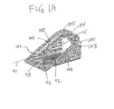
- Figs. 1A , 1B, and 1C are three different views which illustrates an example of a cartridge 100.
- the cartridge 100 has an opening 102 in a housing 103.
- the opening 102 provides access to an interior volume 104 of the cartridge 100.
- There is a sealing surface surface 105 which can be used to attach a lid or a lidding seal such as a metal and/or plastic foil.
- first guiding structure 106 and a supplementary guiding structure 108 There is a first guiding structure 106 and a supplementary guiding structure 108.
- the first guiding structure is shown as being formed as part of a first side wall 107.
- the supplementary guiding structure 108 is show as being formed as part of a second side wall 109.
- both guiding structures 106, 108 are identically formed. They are both ridges of solid material which are aligned with an guiding path 110.
- the Fig. shows how the supplementary guiding structure 108 extends into the interior volume 104.
- the cartridge 100 is formed from a blister pack or thermoformed plastic.
- the first guiding structure 106 extends into the interior volume 104 in the same way that the supplementary guiding structure 108 does.
- the cradle has attached to it a movable needle housing 114 that houses a needle.
- a slot 115 which a mechanism can use to enter and actuate the needle within the removable needle housing 114.
- the backing material 116 is attached to the interior volume 104 at an attachment point 118. In this case it is the portion of the backing material 116 that is closest to the opening 102. As the cradle 112 is removed from the housing 103 the backing material 116 is peeled off from the cradle 112 exposing the adhesive layer.
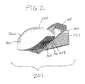
- Fig. 2 shows an example of an inserter 200 being inserted into the cartridge 100 along the guiding path 110.
- the inserter 200 and the cartridge 100 are part of a medical system 201.
- the inserter 200 can be seen as having a cover 202.
- a second guiding structure 206 which is formed as a first groove in the cover 202.
- This second guiding structure 206 mates with the first guiding structure 106.
- Within the second guiding structure 206 is a sliding element 208 which is used to charge or prime an energy storage element within the inserter 200.
- a portion 203 of the inserter 200 is inserted into the cartridge 100.
- the sliding element 208 pushes against the first guiding structure 106 which is a rigid element. This pushes the sliding element 208 back and primes the insertion mechanism.
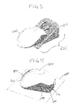
- Fig. 3 shows the inserter 200 after it has been fully inserted into the cartridge 100.
- the cradle 112 including the removable needle housing 114 has been snap-fit into the inserter 200.
- the backing material 116 is also automatically peeled off of the adhesive layer on the underside of the cradle 112.
- Fig. 4 shows the inserter 200 after it has been completely removed from the cartridge 100.
- the sliding element 208 is no longer visible within the groove that forms the second guiding structure 206. It has been depressed into the energy storage component and is now hidden by the cover 202.
- the cradle 112 is on the underside of the inserter 200.
- the cartridge 200 shown in Fig. 4 could be attached to a subject by simply placing the inserter 200 on the surface or skin of a subject.
- Not shown in Fig. 4 is a safety element mechanism which is only engaged when the inserter 200 is placed on a surface.
- the square box 400 is representative of the surface 400 of the subject, which the inserter 200 is being placed on The square box 400 may also represent a surface of the inserter for mounting on the subject.
- Fig. 5 shows the inserter 200 being removed from the cradle 112.
- the insertion mechanism has been actuated and the inserter 200 is then able to be easily slid apart from the cradle 112.
- the cradle 112 is adhered to an adhesive layer 400' which again adheres to the surface 400 of the subject.
- Fig. 6 shows the removable needle housing 114 being removed from the cradle 112.
- the needle is within the removable needle housing 114.
- the removable needle housing 114 functions as a sharps container and the removable needle housing 114 can simply be thrown away.
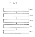
- Fig. 7 shows a flowchart which illustrates a method of operating the medical system 201 shown in Figs. 1-6 .
- a portion 203 of the inserter 200 is moved into the interior volume 104 along the guiding path 110.
- the cradle 112 to attaches to the inserter 200.
- the portion 203 of the inserter 200 and the cradle 112 are removed from the interior volume 104.
- the cradle 112 is attached to an exterior surface of a subject via the adhesive layer 400'.
- the insertion mechanism is operated to actuate the insertion needle to insert a subcutaneous element into the subject.
- step 708 as is shown in Fig. 5 , the inserter 200 is removed from the cradle 112.
- Fig. 8 shows an exploded view of some components of the inserter 200.
- the cover 202 is comprised of a top cover 202' and a bottom cover 202".
- the bottom cover 202" also comprises some fixed elements of the insertion mechanism 800.
- the sliding element 208 which is used to prime the insertion mechanism 800.
- the spring 806 is used to drive a drive arm 808 which forces a needle driver 810 in a downward motion.
- the needle driver 810 is able to go through the slots 115 of the disposable needle enclosure 114.
- the retraction spring 804 withdraws the drive arm 808 back up again to remove the needle from the subject.
- the spring 806 is stronger than the retraction spring 804.
- the drive spring 806 drives the needle driver 810 towards the subject it also applies force to and charges the retraction spring 804.
- the drive spring 806 is then released from the mechanism and the spring 804 is able to return the drive arm 808 and the needle drive 810 to its original starting position.
- the component 204 is a button which is actuated through the top cover 202'.
- the component 812 is a safety element which prevents activation of the insertion mechanism 800 unless the bottom cover 202" is placed on a surface such as a subject.
- Fig. 9 shows a top view of the assembled insertion mechanism 800 of Fig. 8 .
- the sliding element 208 has a sloped surface 14. This is used to engage an end point 816 of the driver spring 806. As the sliding element 208 is moved back the sloped surface 814 lifts the end point 816 and deposits it on a connection point 818 of the drive arm 808. When the drive arm 808 reaches a fully depressed position the end point 816 is forced off of the connection point 818 by a release element 820. In Fig. 8 , it can be seen that in the bottom cover 202" there are a number of structures.
- the sloped component labeled 820 is the release element.
- the release element disengages the end point 816 from the connection point 818 when the drive arm 808 has been fully depressed. After the end point 816 has been disengaged from the connection point 818 the retraction spring 804 is then able to lift the drive arm 808 back into its original position.
- Fig. 10 shows a perspective side view of the assembly drawing in Fig. 9 .
- Fig. 10 it can be seen how the sloped surface 814 engages the end point 816.
- Fig. 10 also is useful for illustrating the function of the safety element 812. Unless the safety element 812 is properly engaged the switch or button 204 is not able to function.
- a sensing point 1000 At the end point of the safety element 812 is a sensing point 1000.
- the sensing point 1000 touches a surface such as the surface of the subject it causes the sensing point to become flush with a mounting surface 1001 and the entire safety element 812 lifts up.
- the dashed region labeled 1002 is shown in an expanded view in Fig. 11 .
- the safety element 812 has a notched region 1100 which locks the button 204 in place.
- the safety element 812 is free and the sensing point 1000 is not touching anything the notched region 1100 falls into place and locks the position of the button 204.
- the sensing point 1000 is placed on a surface it lifts the safety element 812 and the button 204 is free to move. The mechanism may then be activated.
- Figs. 9 , 10 and 11 the insertion mechanism 800 has not yet been primed.
- Fig. 10 and 11 further shows a release pin 1004.
- the release pin 1004 extends through the arm 808 and is supported by the button 204. When the button 204 is depressed the arm 808 is able to be actuated.
- Fig. 12 shows a side view of the insertion mechanism 800 before it has been primed.
- the sliding element 208 has been pushed back by the first guiding structure 106.
- the end point 816 has been lifted by the sloped edge 814 above the connection point 818 of the drive arm 808. It can be seen that the button 204 is holding the arm 808 of the spring above the connection point 818. When the button 204 is depressed the release pin 1004 no longer holds the drive arm 808 such that the arm 808 can move downwards.
- Fig. 13 shows the same view of the insertion mechanism 800 of Fig. 12 but at a slightly different angle and position.
- the release button 204 holds the drive arm 808 in an upper position.
- the drive arm is no longer supported and the drive spring or stored energy component 806 is able to drive and actuate the drive arm 808.
- Fig. 14 shows how the end point 816 of the drive spring 806 is disengaged from the connection point 818 of the drive arm 808.
- the end point 816 of the drive spring 806 comes in contact with a curved surface 1400 of the release element 820.
- the curved surface 1400 physically pushes the end point away and off of the connection point 818.
- the drive spring 806 is no longer engaged and the retraction spring 804 is able to drive the drive arm 808 back into its original position.
- Fig. 15 shows an example of a cradle 112 with a removable needle housing attached.
- the box labeled 1500 shows a zoomed region which is shown in greater detail in Fig. 16.
- Fig. 16 shows how the adhesive layer 400' is attached to the cradle 112.
- the backing material 116 is shown as being attached to the adhesive layer 400'.
- Fig. 17 shows an assembly drawing of the removable needle housing 114.
- the removable needle housing comprises an insertion needle 1700 and a cannula 1702.
- the cannula 1702 could be replaced by additional or different subcutaneous elements such as a sensor and/or additional cannulas.
- the insertion needle 1700 has a mechanism attachment point 1704 for attaching to an insertion mechanism. A portion of a mechanism may be inserted through the slit 115 and may be used to press against the mechanism attachment point 1704 to actuate the needle.
- Fig. 18 shows a cross sectional view of the removable needle housing 114 of Fig. 17 .
- the needle is shown before being inserted into a subject.
- the insertion needle is in the retracted position 1800.
- Fig. 19 shows a further cross sectional view of the removable needle housing 114 of Fig. 17 .
- the insertion needle 1700 has been driven into a subject.
- the cannula 1702 will be left within the subject.
- the insertion needle is shown in the extended position 1900.
- Figs. 20, 21 , and 22 show further views of the inserter 200.
- an additional guiding structure 2000 can be seen. It is able to mate with the supplementary guiding structure 108 shown in Figs 1A , 1B, and 1C .
- An opening 2002 for receiving the removable needle housing 114 is also seen.
- a portion of the needle drive 810 is also shown. The needle driver 810 is able to enter the slot 115 of the removable needle housing 114 to actuate the needle by pressing on the mechanism attachment point 1704.
- Fig. 23 shows a cross sectional view of the inserter 200 that is mounted on a cradle 112.
- the box labeled 2300 shows a region which is enlarged in Fig. 24.
- Fig 24 shows how the cradle 112 is mounted to the bottom of the inserter 200.
- Fig. 25 illustrates how the removable needle 114 assembly interfaces with the inserter 200.
- the cradle 112 is shown as being mounted in the inserter 200.
- the removable needle assembly is moved away from both the cradle 112 and the inserter 200 for clarity.
- the needle drivers 810 would pass through the slots 115 and be used for driving the insertion needle 1700 of Fig. 17 .
- Fig. 26 and Fig. 27 shown an assembly comprising the cradle 112 and an insulin pump 2602.
- the insulin pump is mounted on the cradle 112.
- the insulin pump has been removed from the cradle.
- the cannula 1702 is shown as being inserted into a subject. The insulin pump 2602 is able to attach to the cannula 1702 to pump insulin into the subject.
Landscapes
- Health & Medical Sciences (AREA)
- Vascular Medicine (AREA)
- Engineering & Computer Science (AREA)
- Anesthesiology (AREA)
- Biomedical Technology (AREA)
- Heart & Thoracic Surgery (AREA)
- Hematology (AREA)
- Life Sciences & Earth Sciences (AREA)
- Animal Behavior & Ethology (AREA)
- General Health & Medical Sciences (AREA)
- Public Health (AREA)
- Veterinary Medicine (AREA)
- Dermatology (AREA)
- Infusion, Injection, And Reservoir Apparatuses (AREA)
Abstract

Description
- The invention relates to inserters and disposables for inserting a subcutaneous element into a subject.
- Medical devices are often used as diagnostic devices and/or therapeutic devices in diagnosing and/or treating medical conditions of patients. For example, a blood glucose meter is used as a diagnostic device to measure blood glucose levels of patients suffering from diabetes. An insulin infusion pump is used as a therapeutic device to administer insulin to patients suffering from diabetes.
- Diabetes mellitus, often referred to as diabetes, is a chronic condition in which a person has elevated blood glucose levels that result from defects in the body's ability to produce and/or use insulin. There are three main types of diabetes. Type 1 diabetes may be autoimmune, genetic, and/or environmental and usually strikes children and young adults.
Type 2 diabetes accounts for 90-95% of diabetes cases and is linked to obesity and physical inactivity. Gestational diabetes is a form of glucose intolerance diagnosed during pregnancy and usually resolves spontaneously after delivery. - Diabetes is managed primarily by controlling the level of glucose in the bloodstream. This level complex as the level of blood glucose entering the bloodstream is dynamic and complex, and is affected by multiple factors including the amount and type of food consumed, and the amount of insulin (which mediates transport of glucose across cell membranes) in the blood. Variation of insulin in the bloodstream that controls the transport of glucose out of the bloodstream also complicates diabetes management. Blood glucose levels are also sensitive to diet and exercise, but also can be affected by sleep, stress, smoking, travel, illness, menses, and other psychological and lifestyle factors unique to individual patients. The dynamic nature of blood glucose and insulin and all other factors affecting blood glucose often require a person with diabetes to forecast blood glucose levels. Therefore, therapy in the form of insulin, oral medications, or both can be timed to maintain blood glucose levels in an appropriate range.
- Management of diabetes is time-consuming for patients because of the need to consistently obtain reliable diagnostic information, follow prescribed therapy, and manage lifestyle on a daily basis. Diagnostic information such as blood glucose is typically obtained from a capillary blood sample with a lancing device and is then measured with a handheld blood glucose meter. Interstitial glucose levels may be obtained from a continuous glucose sensor worn on the body. Prescribed therapies may include insulin, oral medications, or both. Insulin can be delivered with a syringe, an ambulatory infusion pump, or a combination of both. With insulin therapy, determining the amount of insulin to be injected can require forecasting meal composition of fat, carbohydrates, and proteins along with effects of exercise or other physiological states. The management of lifestyle factors such as body weight, diet, and exercise can significantly influence the type and effectiveness of therapy.
- The use of a medical appliance that can monitor and/or provide insulin to the patient can be beneficial for maintaining proper glucose levels. The use of a medical appliance may involve mounting a pump or sensor assembly on the body and/or clothing and inserting one or more cannula into the body. This however may be difficult for some patients. The loss of motor skills due to old age, diabetes, or the side effects of insulin itself may make it difficult for a patient to properly mount a pump and/or monitor and to properly insert a cannula or sensor into the body. It is therefore of great benefit to simplify the process using a medical appliance to make it less dependent upon the use of fine motor skills. Furthermore, it is of great benefit to provide a reusable inserter that requires only a few simple handling steps to insert the disposable parts like a cannula and/or a sensor.
- International patent application
WO 2007031126 A1 discloses an insertion head for medical or pharmaceutical applications, comprising: a base with a lower side which can be placed on organic tissue, an insertion device, movably received by the base, which can be inserted into the tissue, said insertion device being movable in relation to the base from a protected position in which a free end of the insertion device is recessed from the lower side of the base to an insertion position in which the free end projects beyond the lower side a handle projecting from the base and comprising a first handle component and a second handle component, movable in relation to the base and the first handle component, and a coupling that translates a movement of the second handle component into a movement of the insertion device. - United States patent
US 7,879,010 discloses a device for inserting a cannula into tissue, including a cannula, a protective element which can accommodate said cannula, an operating element for moving the cannula out of the protective element, and a holder fixedly connected to the cannula. - United States patent
US 7,815,607 discloses an insertion device for an infusion set, the device including a retention means by which the infusion set can be temporarily held on the device and drive means including a pretensionable spring for providing drive energy for an insertion movement of the infusion set. The infusion set is secured by the retention means by clamping when the retention means is in an engage position and can then be moved, with simultaneous pretensioning of the spring, to an insertion movement starting position. The infusion set is already separated from the retention means at the start of the insertion movement. The infusion set moves through at least part of the insertion movement free of the retention means. - The invention provides for a method of using a medical system, a cartridge, an inserter, and a medical system in the independent claims. Embodiments are given in the dependent claims.
- In one aspect the invention provides for a method of using the medical system. The medical system comprises a cartridge and an inserter. In some examples, the inserter is configured to be re-usable rather then a single use diposable inserter.
- The cartridge comprises a housing with an interior volume. The housing comprises a first guiding structure within the interior volume. The cartridge further comprises a cradle for mounting a medical appliance.
- .The cradle comprises a subcutaneous element. The subcutaneous element may for example be one or more cannulas and/or one or more sensors. The one or more sensors may for example include a glucose sensor, a lactate sensor, and an oxygen sensor.
- The cradle is within the interior volume. The cradle further comprises an insertion needle. The insertion needle is configured for being actuated to insert the subcutaneous element into the subject.
- The inserter comprises a second guiding structure for mating with the first guiding structure. The first guiding structure and the second guiding structure are configured for guiding a portion of the inserter into the interior volume along an guiding path. The portion of the inserter is configured for removably attaching to the cradle when guided into the interior volume. The inserter further comprises an insertion mechanism for actuating the insertion needle to insert the subcutaneous element into the subject.
- The method comprises the step of moving the portion of the inserter into the interior volume of the housing along the guiding path or in an insertion direction. Moving the portion of the inserter into the interior volume causes the cradle to attach to the portion. The method further comprises the step of removing the portion of the inserter and the cradle from the interior volume.
- In another embodiment, the cradle comprises an adhesive layer for attaching to an exterior surface of a subject.
- In another embodiment the method further comprises the step of attaching the cradle to the exterior surface of the subject. The method further comprises the step of operating the insertion mechanism to actuate the insertion needle to insert the subcutaneous element into the subject. The method further comprises the step of removing the inserter from the cradle.
- In another embodiment the insertion mechanism comprises a stored energy component for driving the insertion needle into the subject and withdrawal of the insertion needle from the subject. The first guiding structure comprises a rigid element for engaging the stored energy component. The stored energy component is configured for being primed when pressed against the rigid element when the inserter is moved into the interior volume of the housing along the guiding path. The method further comprises priming the stored energy component during the insertion of the portion of the inserter into the interior volume of the housing along the guiding path. This embodiment may be beneficial because the needle is attached to the inserter at the same time that the stored energy component is primed or loaded with energy.
- In another embodiment the cradle comprises a removable needle housing. The insertion needle has an extended position and a retracted position. The insertion needle is within the removable needle housing when in the retracted position. The method further comprises removing the removable needle housing from the cradle after removing the inserter from the cradle. This embodiment may be further beneficial because it provides for a means of disposing of a needle after the insertion has been performed. In some examples the removable needle housing may serve as a disposable sharps container that accompanies the needle.
- In another aspect the invention provides for a cartridge. The cartridge comprises a housing with an interior volume. The housing comprises a first guiding structure within the interior volume for guiding a second guiding structure of an inserter along an guiding path. The cartridge further comprises a cradle for mounting a medical appliance. The cradle comprises a subcutaneous element. The cradle is within the interior volume. The cradle further comprises an insertion needle. The insertion needle is configured for being actuated to insert the subcutaneous element into the subject.
- In another embodiment, the cradle comprises an adhesive layer for attaching to an exterior surface of a subject.
- In another embodiment the first guiding structure comprises a rigid element for engaging the stored energy component of an insertion mechanism of the inserter. In another embodiment the cradle comprises a backing material layer covering the adhesive layer to prevent the adhesive layer from sticking to the interior volume. The housing has an entrance to the interior volume. A portion of the backing material closest to the entrance is attached to the housing. This may be beneficial because a portion of the backing material attached close to the entrance causes the backing material layer to automatically peel off of the adhesive layer as the cradle is removed.
- In another embodiment the attachment of the backing material to the housing is configured to automatically peel the backing from the adhesive layer when the cradle is removed from the housing along the guiding path.
- The portion of the backing material attached to the housing is configured to remain attached to the housing when the cradle is removed from the housing along the guiding path. This may be beneficial because it reduces the number of pieces that a user of the cartridge needs to dispose of.
- In another embodiment the cradle comprises a removable needle housing. The insertion needle has an extended position and a retracted position. The insertion needle is within the removable needle housing when in the retracted position. The removable needle housing may provide a convenient way of disposing of the insertion needle safely as no sharps container is needed for disposal of the insertion needle.
- In another embodiment the removable needle housing comprises at least one slot that is parallel to the insertion needle. The insertion needle comprises a mechanism attachment point for attaching to the insertion mechanism. The at least one slot provides clearance for a mechanism to actuate the insertion needle.
- In another embodiment the housing is a blister pack. This may be beneficial because it provides an inexpensive and sterile packaging for the needle within the housing.
- In some examples, the blister pack may be made of plastic and/or metal based materials. It may be vacuum formed or injection molded.
- In another embodiment the housing has an opening to the interior volume.
- In another embodiment the housing comprises a lid for sealing the opening. The lid may also be referred to as a lid seal or lidding seal. In some examples, the lid is a foil that provides a germ proof or sterile seal. In some examples the lid is attached to the housing via hot melt, thermos, ultrasonic or laser welding
- In another embodiment the lid is formed from any one of the following: aluminum foil, plastic, paper, and combinations thereof.
- In another embodiment the interior volume is sterile.
- In another embodiment the opening is planar.
- In another embodiment the interior volume has a rectangular profile perpendicular to the guiding path. The opening is tilted with respect to the rectangular profile.
- In some examples the housing has a pie shaped profile. A pie shaped profile is a profile that is similar in shape to a sector of a circle or is triangular in shape. The pie shape may have the advantage that is minimizes storage volume and simplifies the handling for the user.
- In another embodiment the opening is tilted with respect to the rectangular profile between 20° and 60°.
- In another embodiment the housing is at least partially formed by a thermal formed plastic.
- In another embodiment the thermal formed plastic is any one of the following: polyvinyl chloride, polychlorotrifluoroethylene, cyclic olefin copolymers, and cyclic olefin polymers.
- In another embodiment the first guiding structure is formed in a first sidewall of the interior volume.
- In another embodiment the rigid structure is formed from a portion of the first sidewall.
- In another embodiment the interior volume has as second sidewall opposing the first sidewall. The sidewall comprises a supplementary guiding structure.
- In another embodiment the supplementary guiding structure is aligned with the guiding path.
- In another embodiment the first guiding structure is aligned with the guiding path.
- In another aspect the invention provides for an inserter. The inserter comprises a second guiding structure for mating with the first guiding structure of a cartridge. The second guiding structure are configured for guiding a portion of the inserter into the interior volume along an guiding path defined by the first guiding structure. The cartridge comprises a cradle. The portion of the inserter is configured for removably attaching to the cradle when guided into the interior volume. The cradle comprises an insertion needle. The inserter further comprises an insertion mechanism for actuating the insertion needle to insert the subcutaneous element into the subject.
- In another embodiment the insertion mechanism comprises an energy storage component for driving the insertion needle into the subject and out of the subject. The first guiding structure comprises a rigid element for engaging the energy storage component. The energy storage component is configured for being primed when pressed against the rigid element when the inserter is moved into the interior volume of the housing along the guiding path.
- In another embodiment the inserter comprises a cover. The second guiding structure is a first groove in the cover. The insertion mechanism comprises a sliding element for sliding within the first groove. The sliding element is configured for priming the energy storage component when moved along the first groove.
- In another embodiment the inserter further comprises an additional guiding structure. The additional guiding structure is a second groove in the cover. The additional guiding structure is aligned with the guiding path.
- In another embodiment the additional guiding structure mates with the supplementary guiding structure.
- In another embodiment the insertion mechanism comprises a button for activating the insertion mechanism when the stored energy component is primed.
- In another embodiment the insertion mechanism comprises a safety element which may also be referred to as a safety or safety mechanism. The safety element extends through the adhesive layer when the stored energy component is primed. The inserter has a mounting surface. The mounting surface is flush with the adhesive layer. The safety element is configured for being depressed flush with the mounting surface when the stored energy component is primed. The insertion mechanism is locked unless the safety element is depressed flush with the mounting surface. This may be beneficial because it may prevent the insertion mechanism from being activated when the inserter is not attached to a subject.
- In another aspect the invention provides for a medical system. The medical system comprises a cartridge according to an embodiment. The medical system further comprises an inserter according to an embodiment.
- In another embodiment the medical system comprises a medical appliance for mounting into the cradle.
- In another embodiment the subcutaneous element comprises at least one cannula. The medical appliance comprises a pumping system. The pumping system comprises any one of the following: an insulin pump for pumping insulin through the at least one cannula, a glucagon pump for pumping glucagon through the at least one cannula, and combinations thereof.
- In another embodiment the subcutaneous element comprises a glucose sensor. The medical appliance comprises a continuous glucose monitor.
- In another embodiment a cradle with one or two cannulas and/or a sensor could be present in a single cradle. In one example the inserter could insert two cannulas at the same time. In another example a cannula and one or more sensors could be inserted at the same time. In another example two cannulas and one or more sensors could be inserted at the same time. In these examples, the inserter mechanism cold actuate multiple insertion needles. In other examples a single needle is used to insert multiple subcutaneous elements.
- In other words a single cradle might have multiple subcutaneous elements that can be inserted by a single inserter.
- In another embodiment the portion of the inserter is configured for forming a snap-fit to removably attach to the cradle when guided into the interior volume.
- It is understood that one or more of the aforementioned embodiments of the invention may be combined as long as the combined embodiments are not mutually exclusive.
- In the following embodiments of the invention are explained in greater detail, by way of example only, making reference to the drawings in which:
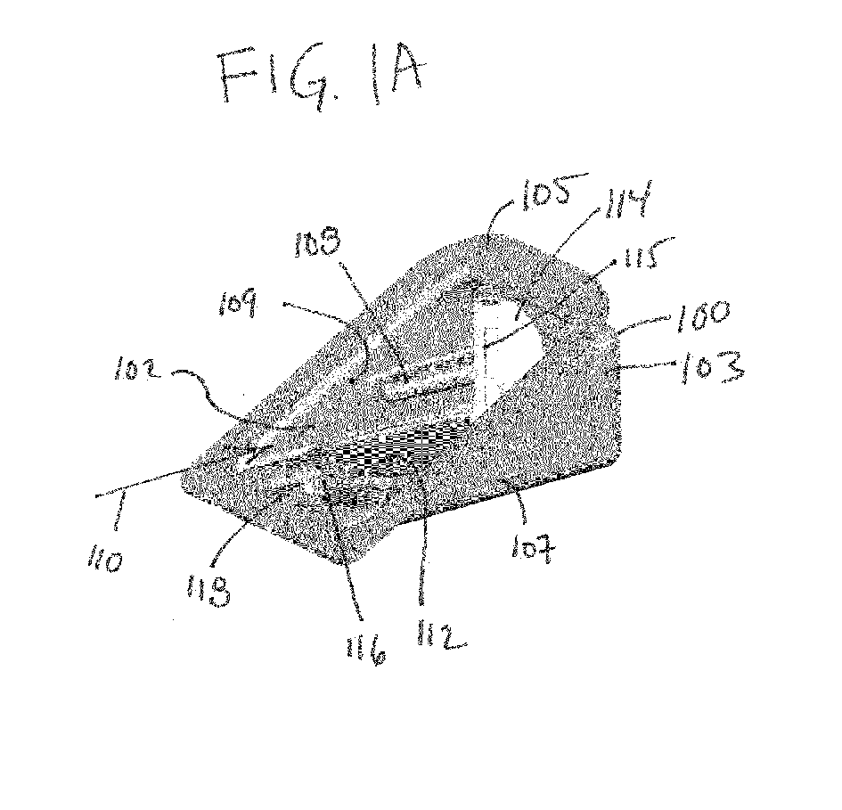
- Fig. 1A
- illustrates an example of a cartridge;
- Fig. 1B
- further illustrates the example of
Fig. 1A ; - Fig. 1C
- further illustrates the example of
Fig. 1A ; - Fig. 2
- illustrates an example of a medical system comprising an inserter and the cartridge of
Fig. 1 ; - Fig. 3
- shows the medical system of
Fig. 2 after the inserter has been inserted into the cartridge; - Fig. 4
- shows the inserter of
Fig. 2 after it has been placed on the surface of a subject; - Fig. 5
- shows the inserter of
Fig. 2 as it is being removed from a cradle; - Fig. 6
- shows a removable needle housing being removed from the cradle of
Fig. 5 ; - Fig. 7
- illustrates a method of operating a medical system as is shown in
Figs. 1 through 6 ; - Fig. 8
- shows an exploded view of an inserter;
- Fig. 9
- shows an assembly drawing of the inserter of
Fig. 8 ; - Fig. 10
- shows a further assembly drawing of the inserter of
Fig. 8 ; - Fig. 11
- shows a further assembly drawing of the inserter of
Fig. 8 ; - Fig. 12
- shows a further assembly drawing of the inserter of
Fig. 8 ; - Fig. 13
- shows a further assembly drawing of the inserter of
Fig. 8 ; and - Fig. 14
- shows a further assembly drawing of the inserter of
Fig. 8 ; - Fig. 15
- shows an example of a cradle with a removable needle housing attached;
- Fig. 16
- shows an enlarged region of
Fig. 15 ; - Fig. 17
- shows an assembly drawing of a removable needle housing;
- Fig. 18
- shows a cross sectional view of the removable needle housing
Fig. 17 ; - Fig. 19
- shows a further cross sectional view of the removable needle housing of
Fig. 17 ; - Fig. 20
- shows a view of an inerter;
- Fig. 21
- shows a further view of an inerter;
- Fig. 22
- shows a further view of an inerter;
- Fig. 23
- shows a cross sectional view of an inserter that is mounted on a cradle;
- Fig. 24
- shows an enlarged region of
Fig. 23 ; - Fig. 25
- illustrates an example of how a removable needle assembly interfaces with an inserter;
- Fig. 26
- shows an insulin pump mounted on a cradle: and
- Fig. 27
- shows an exploded view of the insulin pump and cradle of
Fig. 26 . - Like numbered elements in these figures are either equivalent elements or perform the same function. Elements which have been discussed previously will not necessarily be discussed in later figures if the function is equivalent.
-
Figs. 1A ,1B, and 1C are three different views which illustrates an example of acartridge 100. Thecartridge 100 has anopening 102 in ahousing 103. Theopening 102 provides access to an interior volume 104 of thecartridge 100. There is a sealingsurface surface 105 which can be used to attach a lid or a lidding seal such as a metal and/or plastic foil. - There is a
first guiding structure 106 and asupplementary guiding structure 108. The first guiding structure is shown as being formed as part of afirst side wall 107. Thesupplementary guiding structure 108 is show as being formed as part of asecond side wall 109. In this example both guidingstructures path 110. The Fig. shows how thesupplementary guiding structure 108 extends into the interior volume 104. In this example thecartridge 100 is formed from a blister pack or thermoformed plastic. Thefirst guiding structure 106 extends into the interior volume 104 in the same way that thesupplementary guiding structure 108 does. - Within the interior volume 104 there is a
cradle 112. The cradle has attached to it amovable needle housing 114 that houses a needle. There is aslot 115 which a mechanism can use to enter and actuate the needle within theremovable needle housing 114. On the underside of thecradle 112 there is abacking material 116 which protects a an adhesive layer. Thebacking material 116 is attached to the interior volume 104 at anattachment point 118. In this case it is the portion of thebacking material 116 that is closest to theopening 102. As thecradle 112 is removed from thehousing 103 thebacking material 116 is peeled off from thecradle 112 exposing the adhesive layer. -
Fig. 2 shows an example of aninserter 200 being inserted into thecartridge 100 along the guidingpath 110. Theinserter 200 and thecartridge 100 are part of amedical system 201. Theinserter 200 can be seen as having acover 202. There is abutton 204 on theinserter 200 to fire an insertion mechanism which is contained within thecover 202. InFig. 2 there can be seen asecond guiding structure 206 which is formed as a first groove in thecover 202. Thissecond guiding structure 206 mates with thefirst guiding structure 106. Within thesecond guiding structure 206 is a slidingelement 208 which is used to charge or prime an energy storage element within theinserter 200. Aportion 203 of theinserter 200 is inserted into thecartridge 100. As this is done, the slidingelement 208 pushes against thefirst guiding structure 106 which is a rigid element. This pushes the slidingelement 208 back and primes the insertion mechanism. On the far side of thecover 202 there is also an additional guiding structure which mates with thesupplementary guiding structure 108. There is also a groove in thecover 202 that is used to help align and make theinserter 200 better follow the guidingpath 110. -
Fig. 3 shows theinserter 200 after it has been fully inserted into thecartridge 100. Thecradle 112 including theremovable needle housing 114 has been snap-fit into theinserter 200. As theinserter 200 is withdrawn in the opposite direction to the guidingpath 110 thecradle 112 is automatically removed. Thebacking material 116 is also automatically peeled off of the adhesive layer on the underside of thecradle 112. -
Fig. 4 shows theinserter 200 after it has been completely removed from thecartridge 100. The slidingelement 208 is no longer visible within the groove that forms thesecond guiding structure 206. It has been depressed into the energy storage component and is now hidden by thecover 202. Thecradle 112 is on the underside of theinserter 200. Thecartridge 200 shown inFig. 4 could be attached to a subject by simply placing theinserter 200 on the surface or skin of a subject. Not shown inFig. 4 is a safety element mechanism which is only engaged when theinserter 200 is placed on a surface. Thesquare box 400 is representative of thesurface 400 of the subject, which theinserter 200 is being placed on Thesquare box 400 may also represent a surface of the inserter for mounting on the subject. -
Fig. 5 shows theinserter 200 being removed from thecradle 112. The insertion mechanism has been actuated and theinserter 200 is then able to be easily slid apart from thecradle 112. Thecradle 112 is adhered to an adhesive layer 400' which again adheres to thesurface 400 of the subject. -
Fig. 6 shows theremovable needle housing 114 being removed from thecradle 112. The needle is within theremovable needle housing 114. Theremovable needle housing 114 functions as a sharps container and theremovable needle housing 114 can simply be thrown away. -
Fig. 7 shows a flowchart which illustrates a method of operating themedical system 201 shown inFigs. 1-6 . First in step 700 aportion 203 of theinserter 200 is moved into the interior volume 104 along the guidingpath 110. After the inserter has be moved along the guidingpath 110 thecradle 112 to attaches to theinserter 200. Next instep 702 theportion 203 of theinserter 200 and thecradle 112 are removed from the interior volume 104. Next instep 704 thecradle 112 is attached to an exterior surface of a subject via the adhesive layer 400'. Next in step 706 the insertion mechanism is operated to actuate the insertion needle to insert a subcutaneous element into the subject. Finally instep 708, as is shown inFig. 5 , theinserter 200 is removed from thecradle 112. -
Fig. 8 shows an exploded view of some components of theinserter 200. Thecover 202 is comprised of a top cover 202' and abottom cover 202". Thebottom cover 202" also comprises some fixed elements of theinsertion mechanism 800. In the components there can be seen the slidingelement 208 which is used to prime theinsertion mechanism 800. When the slidingelement 208 is depressed it charges, loads, or primes adrive spring 806 or a storedenergy component 806. Thespring 806 is used to drive adrive arm 808 which forces aneedle driver 810 in a downward motion. Theneedle driver 810 is able to go through theslots 115 of thedisposable needle enclosure 114. After thedrive arm 808 has been depressed theretraction spring 804 withdraws thedrive arm 808 back up again to remove the needle from the subject. Thespring 806 is stronger than theretraction spring 804. As thedrive spring 806 drives theneedle driver 810 towards the subject it also applies force to and charges theretraction spring 804. Thedrive spring 806 is then released from the mechanism and thespring 804 is able to return thedrive arm 808 and theneedle drive 810 to its original starting position. Thecomponent 204 is a button which is actuated through the top cover 202'. Thecomponent 812 is a safety element which prevents activation of theinsertion mechanism 800 unless thebottom cover 202" is placed on a surface such as a subject. -
Fig. 9 shows a top view of the assembledinsertion mechanism 800 ofFig. 8 . The slidingelement 208 has a sloped surface 14. This is used to engage anend point 816 of thedriver spring 806. As the slidingelement 208 is moved back the slopedsurface 814 lifts theend point 816 and deposits it on aconnection point 818 of thedrive arm 808. When thedrive arm 808 reaches a fully depressed position theend point 816 is forced off of theconnection point 818 by arelease element 820. InFig. 8 , it can be seen that in thebottom cover 202" there are a number of structures. The sloped component labeled 820 is the release element. The release element disengages theend point 816 from theconnection point 818 when thedrive arm 808 has been fully depressed. After theend point 816 has been disengaged from theconnection point 818 theretraction spring 804 is then able to lift thedrive arm 808 back into its original position. -
Fig. 10 shows a perspective side view of the assembly drawing inFig. 9 . In particular inFig. 10 it can be seen how the slopedsurface 814 engages theend point 816.Fig. 10 also is useful for illustrating the function of thesafety element 812. Unless thesafety element 812 is properly engaged the switch orbutton 204 is not able to function. At the end point of thesafety element 812 is asensing point 1000. When thesensing point 1000 touches a surface such as the surface of the subject it causes the sensing point to become flush with a mountingsurface 1001 and theentire safety element 812 lifts up. The dashed region labeled 1002 is shown in an expanded view inFig. 11 . Thesafety element 812 has a notchedregion 1100 which locks thebutton 204 in place. When thesafety element 812 is free and thesensing point 1000 is not touching anything the notchedregion 1100 falls into place and locks the position of thebutton 204. When thesensing point 1000 is placed on a surface it lifts thesafety element 812 and thebutton 204 is free to move. The mechanism may then be activated. InFigs. 9 ,10 and11 theinsertion mechanism 800 has not yet been primed. -
Fig. 10 and11 further shows arelease pin 1004. Therelease pin 1004 extends through thearm 808 and is supported by thebutton 204. When thebutton 204 is depressed thearm 808 is able to be actuated. -
Fig. 12 shows a side view of theinsertion mechanism 800 before it has been primed. The slidingelement 208 has been pushed back by thefirst guiding structure 106. Theend point 816 has been lifted by the slopededge 814 above theconnection point 818 of thedrive arm 808. It can be seen that thebutton 204 is holding thearm 808 of the spring above theconnection point 818. When thebutton 204 is depressed therelease pin 1004 no longer holds thedrive arm 808 such that thearm 808 can move downwards. -
Fig. 13 shows the same view of theinsertion mechanism 800 ofFig. 12 but at a slightly different angle and position. InFig. 13 it can be seen how therelease button 204 holds thedrive arm 808 in an upper position. When thebutton 204 is depressed the drive arm is no longer supported and the drive spring or storedenergy component 806 is able to drive and actuate thedrive arm 808. -
Fig. 14 shows how theend point 816 of thedrive spring 806 is disengaged from theconnection point 818 of thedrive arm 808. As thedrive arm 808 is depressed theend point 816 of thedrive spring 806 comes in contact with a curved surface 1400 of therelease element 820. As thedrive arm 808 reaches its fully depressed position the curved surface 1400 physically pushes the end point away and off of theconnection point 818. At this point thedrive spring 806 is no longer engaged and theretraction spring 804 is able to drive thedrive arm 808 back into its original position. -
Fig. 15 shows an example of acradle 112 with a removable needle housing attached. The box labeled 1500 shows a zoomed region which is shown in greater detail inFig. 16. Fig. 16 shows how the adhesive layer 400' is attached to thecradle 112. Thebacking material 116 is shown as being attached to the adhesive layer 400'. -
Fig. 17 shows an assembly drawing of theremovable needle housing 114. The removable needle housing comprises aninsertion needle 1700 and acannula 1702. Thecannula 1702 could be replaced by additional or different subcutaneous elements such as a sensor and/or additional cannulas. Theinsertion needle 1700 has amechanism attachment point 1704 for attaching to an insertion mechanism. A portion of a mechanism may be inserted through theslit 115 and may be used to press against themechanism attachment point 1704 to actuate the needle. -
Fig. 18 shows a cross sectional view of theremovable needle housing 114 ofFig. 17 . In this cross sectional view, the needle is shown before being inserted into a subject. InFig. 18 , the insertion needle is in the retractedposition 1800. -
Fig. 19 shows a further cross sectional view of theremovable needle housing 114 ofFig. 17 . In this Fig., theinsertion needle 1700 has been driven into a subject. When theinsertion needle 1700 is withdrawn, thecannula 1702 will be left within the subject. InFig. 19 the insertion needle is shown in theextended position 1900. -
Figs. 20, 21 , and22 show further views of theinserter 200. InFigs. 20 and 21 anadditional guiding structure 2000 can be seen. It is able to mate with thesupplementary guiding structure 108 shown inFigs 1A ,1B, and 1C . Anopening 2002 for receiving theremovable needle housing 114 is also seen. A portion of theneedle drive 810 is also shown. Theneedle driver 810 is able to enter theslot 115 of theremovable needle housing 114 to actuate the needle by pressing on themechanism attachment point 1704. -
Fig. 23 shows a cross sectional view of theinserter 200 that is mounted on acradle 112. The box labeled 2300 shows a region which is enlarged inFig. 24. Fig 24 shows how thecradle 112 is mounted to the bottom of theinserter 200. -
Fig. 25 illustrates how theremovable needle 114 assembly interfaces with theinserter 200. In this Fig. thecradle 112 is shown as being mounted in theinserter 200. The removable needle assembly is moved away from both thecradle 112 and theinserter 200 for clarity. Theneedle drivers 810 would pass through theslots 115 and be used for driving theinsertion needle 1700 ofFig. 17 . As theinserter 200 is slid onto the cradle twogripping elements 2500 would grip agripping location 2502 of theremovable needle assembly 114. -
Fig. 26 and Fig. 27 shown an assembly comprising thecradle 112 and aninsulin pump 2602. InFig. 26 the insulin pump is mounted on thecradle 112. In.Fig. 27 the insulin pump has been removed from the cradle. InFig. 27 , thecannula 1702 is shown as being inserted into a subject. Theinsulin pump 2602 is able to attach to thecannula 1702 to pump insulin into the subject. -
- 100
- cartridge
- 102
- opening
- 103
- housing
- 104
- interior volume
- 105
- sealing surface
- 106
- first guiding structure
- 107
- first side wall
- 108
- supplementary guiding structure
- 109
- second side wall
- 110
- guiding path
- 112
- cradle
- 114
- removable needle housing
- 115
- slot
- 116
- backing material
- 118
- attachment point
- 200
- inserter
- 201
- medical system
- 202
- cover
- 202'
- top cover
- 202"
- bottom cover
- 203
- portion of inserter
- 204
- button
- 206
- second guiding structure
- 208
- sliding element
- 400
- surface of subject
- 400'
- adhesive layer
- 700
- move at least a portion of the inserter into the interior volume of the housing along the guiding path
- 702
- remove the inserter and the cradle from the interior volume
- 704
- attach the cradle to the exterior surface of the subject
- 706
- operate the insertion mechanism to actuate the insertion needle to insert the subcutaneous element into the subject
- 708
- remove the inserter from the cradle
- 800
- insertion mechanism
- 802
- priming spring
- 804
- retraction spring
- 806
- drive spring or stored energy component
- 808
- drive arm
- 810
- needle driver
- 812
- safety element
- 814
- sloped surface
- 816
- end point
- 818
- connection point
- 820
- release element
- 1000
- sensing point
- 1001
- mounting surface
- 1002
- zoomed region
- 1004
- release pin
- 1100
- notched region
- 1400
- curved surface
- 1500
- zoomed region
- 1700
- insertion needle
- 1702
- cannula
- 1704
- mechanism attachment point
- 1800
- retracted position
- 1900
- extended position
- 2000
- additional guiding structure
- 2002
- opening
- 2300
- zoomed region
- 2500
- gripping element
- 2502
- gripping location
- 2600
- assembly
- 2602
- insulin pump
Claims (19)
- A method of using a medical system (201), wherein the medical system comprises a cartridge (100) and an inserter (200), wherein the cartridge comprises:- a housing (103) with an interior volume (104), wherein the housing comprises a first guiding structure (106) within the interior volume;- a cradle (112) for mounting a medical appliance, wherein the cradle comprises a subcutaneous element, wherein the cradle is within the interior volume, wherein the cradle further comprises an insertion needle, wherein the insertion needle is configured for being actuated to insert the subcutaneous element into the subject;
wherein the inserter comprises:- a second guiding structure (206) for mating with the first guiding structure,
wherein the first guiding structure and the second guiding structure are configured for guiding at least a portion (203) of the inserter into the interior volume along a guiding path (110), wherein the portion of the inserter is configured for removably attaching to the cradle when guided into the interior volume;- an insertion mechanism for actuating the insertion needle to insert the subcutaneous element into the subject;
wherein the method comprises the steps of:- moving (700) at least a portion of the inserter into the interior volume of the housing along the guiding path, wherein moving the inserter into the interior volume causes the cradle to attach to the inserter;- removing (702) the inserter and the cradle from the interior volume;- attaching (704) the cradle to the exterior surface of the subject;- operating (706) the insertion mechanism to actuate the insertion needle to insert the subcutaneous element into the subject; and- removing (708) the inserter from the cradle. - The method of claim 1, wherein the insertion mechanism comprises a stored energy component (806, 208) for driving the insertion needle into the subject and withdrawal of the insertion needle from the subject, wherein the housing and preferably the first guiding structure comprises a rigid element (106) for engaging the stored energy component, wherein the stored energy component is configured for being primed when pressed against the rigid element when the inserter is moved into the interior volume of the housing along the guiding path, wherein the method further comprises priming the stored energy component during the insertion of the inserter into the interior volume of the housing along the guiding path.
- A cartridge (100), wherein wherein the cartridge comprises:- a housing (103) with an interior volume (104), wherein the housing comprises a first guiding structure (106) within the interior volume for guiding a second guiding structure (206) of an inserter (200) along an guiding path; and- a cradle (112) for mounting a medical appliance, wherein the cradle comprises a subcutaneous element, wherein the cradle is within the interior volume, wherein the cradle further comprises an insertion needle, wherein the insertion needle is configured for being actuated to insert the subcutaneous element into the subject.
- The cartridge of claim 3, wherein the housing and preferably the first guiding structure comprises a rigid element (106) for engaging a stored energy component (806, 208) of an insertion mechanism (208) of the inserter.
- The cartridge of claim 3 or 4, wherein the cradle comprises an adhesive layer for attaching to an exterior surface of a subject, wherein the cradle comprises a backing material layer (116) covering the adhesive layer to prevent the adhesive layer from sticking to the interior volume, wherein the housing has an opening (102), wherein a portion (118) of the backing material is attached to the housing.
- The cartridge of claim 5, wherein the attachment of the backing material to the housing is configured to peel the backing from the adhesive layer when the cradle is removed from the housing.
- The cartridge of claim 5 or 6, wherein the portion of the backing material attached to the housing is configured to remain attached to the housing when the cradle is removed from the housing along the guiding path.
- The cartridge of any one of claims 3 through 7, wherein the housing has an opening (102) to the interior volume, wherein the opening is planar, wherein the interior volume has a rectangular profile perpendicular to the guiding path, wherein the opening is tilted with respect to the rectangular profile such that the housing has a pie-type shape..
- The cartridge of claim 8, wherein the opening is tilted with respect to the rectangular profile between 20 degrees and 60 degrees.
- The cartridge of any one of claims 3 through 9, wherein the first guiding structure is formed in a first side wall (107) of the interior volume, and wherein the rigid element is formed from a portion of the first side wall.
- The cartridge of claim 10, wherein the interior volume has a second side wall (109) opposing the first side wall, wherein the second side wall comprises a supplementary guiding structure
- An inserter (200),
wherein the inserter comprises:- a second guiding structure (206) for mating with a housing of a cartridge (100), wherein the second guiding structure are configured for guiding the inserter into the interior volume along an guiding path defined by the first guiding structure, wherein the cartridge comprises a cradle (112), wherein the portion of the inserter is configured for removably attaching to the cradle when guided into the interior volume, wherein the cradle comprises an insertion needle; and- an insertion mechanism (208) for actuating the insertion needle to insert the subcutaneous element into the subject; - The inserter of claim 12, wherein the insertion mechanism comprises an energy storage component (208, 806) for driving the insertion needle into the subject and out of the the subject, wherein the housing comprises a rigid element (106) for engaging the energy storage component, wherein the energy storage component is configured for being primed when pressed against the rigid element when the inserter is moved into the interior volume of the housing along the guiding path.
- The inserter of claim 13, wherein inserter comprises a cover, wherein the second guiding structure is a first groove in the cover, wherein the insertion mechanism comprises a sliding element (806) for sliding within the first groove, and wherein the sliding element is configured for priming the energy storage component when moved along the first groove.
- The inserter of claim 14, wherein the inserter further comprises an additional guiding structure (2000), wherein the additional guiding structure is a second groove in the cover, wherein the additional guiding structure is aligned with the guiding path.
- The inserter of any one of claims 12 through 15, wherein insertion mechanism comprises a button (204) for activating the insertion mechanism when the stored energy component is primed.
- The inserter of any one of claims 12 through 16, wherein the insertion mechanism comprises a safety element (812), wherein the inserter has a mounting surface (1001),, wherein the safety element extends through the mounting surface when the stored energy component is primed, wherein the safety element is configured for being depressed flush with the mounting when the stored energy component is primed, wherein the insertion mechanism is locked unless the safety element is depressed flush with the mounting surface.
- The inserter of any one of claims 12 through 17, wherein at least a portion of the inserter mates with the interior volume of the cartridge.
- A medical system, wherein the medical system comprises a cartridge (100) according to any any one of claims 3 through 11, wherein the medical system further comprises an inserter (200) according to any one of claims 12 through 18.
Priority Applications (12)
| Application Number | Priority Date | Filing Date | Title |
|---|---|---|---|
| EP15169214.2A EP3097933B1 (en) | 2015-05-26 | 2015-05-26 | Cartridge and inserter for a medical system |
| ES15169214T ES2753453T3 (en) | 2015-05-26 | 2015-05-26 | Cartridge and inserter for a medical system |
| PL15169214T PL3097933T3 (en) | 2015-05-26 | 2015-05-26 | Cartridge and inserter for a medical system |
| DK15169214T DK3097933T3 (en) | 2015-05-26 | 2015-05-26 | Cartridge and medical device insertion unit |
| SI201530967T SI3097933T1 (en) | 2015-05-26 | 2015-05-26 | Cartridge and inserter for a medical system |
| HK18107249.4A HK1247869B (en) | 2015-05-26 | 2016-05-25 | Cartridge and inserter for a medical system |
| CN201680023150.1A CN107438441B (en) | 2015-05-26 | 2016-05-25 | Cartridge and inserter for medical system |
| PCT/EP2016/061860 WO2016189066A1 (en) | 2015-05-26 | 2016-05-25 | Cartridge and inserter for a medical system |
| RU2017134845A RU2728843C2 (en) | 2015-05-26 | 2016-05-25 | Cartridge and insertion tool for medical system |
| CA2980105A CA2980105C (en) | 2015-05-26 | 2016-05-25 | Cartridge and inserter for a medical system |
| US15/821,482 US10737021B2 (en) | 2015-05-26 | 2017-11-22 | Cartridge and inserter for a medical system |
| US16/917,059 US11793934B2 (en) | 2015-05-26 | 2020-06-30 | Cartridge and inserter for a medical system |
Applications Claiming Priority (1)
| Application Number | Priority Date | Filing Date | Title |
|---|---|---|---|
| EP15169214.2A EP3097933B1 (en) | 2015-05-26 | 2015-05-26 | Cartridge and inserter for a medical system |
Publications (2)
| Publication Number | Publication Date |
|---|---|
| EP3097933A1 true EP3097933A1 (en) | 2016-11-30 |
| EP3097933B1 EP3097933B1 (en) | 2019-09-04 |
Family
ID=53264536
Family Applications (1)
| Application Number | Title | Priority Date | Filing Date |
|---|---|---|---|
| EP15169214.2A Active EP3097933B1 (en) | 2015-05-26 | 2015-05-26 | Cartridge and inserter for a medical system |
Country Status (10)
| Country | Link |
|---|---|
| US (2) | US10737021B2 (en) |
| EP (1) | EP3097933B1 (en) |
| CN (1) | CN107438441B (en) |
| CA (1) | CA2980105C (en) |
| DK (1) | DK3097933T3 (en) |
| ES (1) | ES2753453T3 (en) |
| PL (1) | PL3097933T3 (en) |
| RU (1) | RU2728843C2 (en) |
| SI (1) | SI3097933T1 (en) |
| WO (1) | WO2016189066A1 (en) |
Families Citing this family (14)
| Publication number | Priority date | Publication date | Assignee | Title |
|---|---|---|---|---|
| PT1762259E (en) | 2005-09-12 | 2010-12-10 | Unomedical As | INSERTER FOR AN INFUSION ASSEMBLY WITH A FIRST AND SECOND SPRING UNITS |
| JP2013523233A (en) | 2010-03-30 | 2013-06-17 | ウノメディカル アクティーゼルスカブ | Medical device |
| US10194938B2 (en) | 2011-03-14 | 2019-02-05 | UnoMedical, AS | Inserter system with transport protection |
| EP2583715A1 (en) | 2011-10-19 | 2013-04-24 | Unomedical A/S | Infusion tube system and method for manufacture |
| USD794201S1 (en) | 2015-07-09 | 2017-08-08 | Dexcom, Inc. | Medical device electronic module |
| USD794800S1 (en) | 2015-07-09 | 2017-08-15 | Dexcom, Inc. | Medical device inserter |
| USD794801S1 (en) | 2015-07-09 | 2017-08-15 | Dexcom, Inc. | Base for medical device electronic module |
| EP3754011B1 (en) | 2015-09-09 | 2022-02-16 | Drawbridge Health, Inc. | Devices for sample collection, stabilization and preservation |
| EP4740989A2 (en) | 2016-01-19 | 2026-05-13 | Unomedical A/S | Cannula & infusion devices |
| CN115251923A (en) | 2017-01-10 | 2022-11-01 | 集联健康有限公司 | Devices, systems, and methods for sample collection |
| EP3928688B1 (en) | 2017-06-23 | 2022-06-01 | Dexcom, Inc. | Transcutaneous analyte sensors, applicators therefor, and needle hub comprising anti-rotation feature |
| EP3669906B1 (en) | 2018-12-21 | 2023-09-20 | Roche Diabetes Care GmbH | Skin-mountable medical device |
| CA3141608A1 (en) | 2019-05-20 | 2020-11-26 | Unomedical A/S | Rotatable infusion device and methods thereof |
| KR20250096705A (en) | 2022-10-21 | 2025-06-27 | 에프. 호프만-라 로슈 아게 | Insertion system and method for inserting a medical device |
Citations (7)
| Publication number | Priority date | Publication date | Assignee | Title |
|---|---|---|---|---|
| US20040133164A1 (en) * | 2002-11-05 | 2004-07-08 | Funderburk Jeffery V. | Sensor inserter device and methods of use |
| EP1475113A1 (en) * | 2003-05-08 | 2004-11-10 | Novo Nordisk A/S | External needle inserter |
| WO2007031126A1 (en) | 2005-09-15 | 2007-03-22 | F. Hoffmann-La Roche Ag | Insertion head with handle |
| WO2010003886A1 (en) * | 2008-07-07 | 2010-01-14 | Unomedical A/S | Inserter for transcutaneous device |
| US7815607B2 (en) | 2007-03-14 | 2010-10-19 | Roche Diagnostics International Ag | Insertion device for an insertion head, in particular for an infusion set |
| US7879010B2 (en) | 2001-04-06 | 2011-02-01 | Roche Diagnostics International Ag | Infusion set |
| WO2012108959A1 (en) * | 2011-02-09 | 2012-08-16 | Becton, Dickinson And Company | Folding inserter for drug delivery infusion set |
Family Cites Families (39)
| Publication number | Priority date | Publication date | Assignee | Title |
|---|---|---|---|---|
| ATE474611T1 (en) * | 2003-05-08 | 2010-08-15 | Novo Nordisk As | AN INJECTION DEVICE THAT CAN BE APPLIED TO THE SKIN WITH A SEPARABLE ACTUATING PART FOR INSERTING THE NEEDLE |
| US6926694B2 (en) | 2003-05-09 | 2005-08-09 | Medsolve Technologies, Llc | Apparatus and method for delivery of therapeutic and/or diagnostic agents |
| ATE364424T1 (en) * | 2003-07-21 | 2007-07-15 | Disetronic Licensing Ag | INJECTION DEVICE FOR INJECTION NEEDLE |
| US7731691B2 (en) * | 2003-11-10 | 2010-06-08 | Smiths Medical Asd, Inc. | Subcutaneous infusion device and device for insertion of a cannula of an infusion device and method |
| MXPA06010784A (en) | 2004-03-26 | 2006-12-15 | Unomedical As | Injector device for infusion set. |
| US7857760B2 (en) | 2004-07-13 | 2010-12-28 | Dexcom, Inc. | Analyte sensor |
| US8989833B2 (en) * | 2004-07-13 | 2015-03-24 | Dexcom, Inc. | Transcutaneous analyte sensor |
| DE102004039408A1 (en) | 2004-08-13 | 2006-03-02 | Disetronic Licensing Ag | Insertion head for medical or pharmaceutical applications |
| US8029441B2 (en) * | 2006-02-28 | 2011-10-04 | Abbott Diabetes Care Inc. | Analyte sensor transmitter unit configuration for a data monitoring and management system |
| WO2006077262A1 (en) * | 2005-01-24 | 2006-07-27 | Novo Nordisk A/S | Medical device with protected transcutaneous device |
| PT1762259E (en) * | 2005-09-12 | 2010-12-10 | Unomedical As | INSERTER FOR AN INFUSION ASSEMBLY WITH A FIRST AND SECOND SPRING UNITS |
| MX2008010341A (en) * | 2006-02-09 | 2008-11-18 | Deka Products Lp | Peripheral systems. |
| CN101426542A (en) | 2006-04-26 | 2009-05-06 | 诺沃-诺迪斯克有限公司 | Skin-mountable device in packaging comprising coated seal member |
| US9399094B2 (en) | 2006-06-06 | 2016-07-26 | Novo Nordisk A/S | Assembly comprising skin-mountable device and packaging therefore |
| EP2023818A2 (en) | 2006-06-07 | 2009-02-18 | Unomedical A/S | Inserter for transcutaneous sensor |
| US8790311B2 (en) | 2006-06-09 | 2014-07-29 | Unomedical A/S | Mounting pad |
| AU2007280850B9 (en) | 2006-08-02 | 2010-09-02 | Unomedical A/S | Cannula and delivery device |
| WO2008065646A1 (en) | 2006-11-28 | 2008-06-05 | Medingo Ltd. | An insertion device and method for inserting a subcutaneously insertable element into a body |
| LT3632488T (en) * | 2006-12-22 | 2023-07-25 | Roche Diabetes Care Gmbh | Device for sustained delivery of a therapeutic fluid |
| DK1970091T3 (en) * | 2007-03-14 | 2011-02-21 | Hoffmann La Roche | Introductory head for medical or pharmaceutical applications |
| US8323250B2 (en) * | 2007-04-30 | 2012-12-04 | Medtronic Minimed, Inc. | Adhesive patch systems and methods |
| EP2146760B1 (en) * | 2007-04-30 | 2018-10-10 | Medtronic MiniMed, Inc. | Reservoir filling, bubble management, and infusion medium delivery systems and methods with same |
| US8002752B2 (en) * | 2007-06-25 | 2011-08-23 | Medingo, Ltd. | Protector apparatus |
| AU2009219678A1 (en) | 2008-02-27 | 2009-09-03 | Mon4D Ltd. | Device, system and method for modular analyte monitoring |
| EP3639869A1 (en) * | 2008-04-09 | 2020-04-22 | Roche Diabetes Care GmbH | Systems, devices and methods for fluid delivery |
| MX2010014260A (en) | 2008-07-07 | 2011-03-21 | Unomedical As | Inserter for transcutaneous device. |
| CA2736320A1 (en) | 2008-09-29 | 2010-04-01 | Unomedical A/S | Packing for inserter |
| CA2766685A1 (en) | 2010-03-24 | 2011-12-29 | Abbott Diabetes Care Inc. | Medical device inserters and processes of inserting and using medical devices |
| JP2013523233A (en) | 2010-03-30 | 2013-06-17 | ウノメディカル アクティーゼルスカブ | Medical device |
| WO2011160244A1 (en) * | 2010-06-21 | 2011-12-29 | F. Hoffmann-La Roche Ag | Device for inserting an insertion member into the tissue of the body of a patient |
| US8668675B2 (en) * | 2010-11-03 | 2014-03-11 | Flugen, Inc. | Wearable drug delivery device having spring drive and sliding actuation mechanism |
| US8905972B2 (en) * | 2010-11-20 | 2014-12-09 | Perqflo, Llc | Infusion pumps |
| US8795230B2 (en) * | 2010-11-30 | 2014-08-05 | Becton, Dickinson And Company | Adjustable height needle infusion device |
| WO2012118872A2 (en) * | 2011-02-28 | 2012-09-07 | Abbott Diabetes Care Inc. | Medical device inserters and processes of inserting and using medical devices |
| WO2013035455A1 (en) | 2011-09-09 | 2013-03-14 | テルモ株式会社 | Sensor insertion device and method for operating same |
| CA2806765C (en) * | 2012-03-08 | 2020-09-22 | Isense Corporation | Method and apparatus for insertion of a sensor |
| US9931065B2 (en) * | 2012-04-04 | 2018-04-03 | Dexcom, Inc. | Transcutaneous analyte sensors, applicators therefor, and associated methods |
| EP2668901A1 (en) | 2012-05-31 | 2013-12-04 | Roche Diagniostics GmbH | Sensor insertion assembly, sensor cartridge, and inserter |
| US9731069B2 (en) | 2012-09-27 | 2017-08-15 | Becton, Dickinson And Company | Perpendicular infusion set and disposable inserter |
-
2015
- 2015-05-26 ES ES15169214T patent/ES2753453T3/en active Active
- 2015-05-26 EP EP15169214.2A patent/EP3097933B1/en active Active
- 2015-05-26 PL PL15169214T patent/PL3097933T3/en unknown
- 2015-05-26 DK DK15169214T patent/DK3097933T3/en active
- 2015-05-26 SI SI201530967T patent/SI3097933T1/en unknown
-
2016
- 2016-05-25 CA CA2980105A patent/CA2980105C/en active Active
- 2016-05-25 CN CN201680023150.1A patent/CN107438441B/en active Active
- 2016-05-25 WO PCT/EP2016/061860 patent/WO2016189066A1/en not_active Ceased
- 2016-05-25 RU RU2017134845A patent/RU2728843C2/en active
-
2017
- 2017-11-22 US US15/821,482 patent/US10737021B2/en active Active
-
2020
- 2020-06-30 US US16/917,059 patent/US11793934B2/en active Active
Patent Citations (7)
| Publication number | Priority date | Publication date | Assignee | Title |
|---|---|---|---|---|
| US7879010B2 (en) | 2001-04-06 | 2011-02-01 | Roche Diagnostics International Ag | Infusion set |
| US20040133164A1 (en) * | 2002-11-05 | 2004-07-08 | Funderburk Jeffery V. | Sensor inserter device and methods of use |
| EP1475113A1 (en) * | 2003-05-08 | 2004-11-10 | Novo Nordisk A/S | External needle inserter |
| WO2007031126A1 (en) | 2005-09-15 | 2007-03-22 | F. Hoffmann-La Roche Ag | Insertion head with handle |
| US7815607B2 (en) | 2007-03-14 | 2010-10-19 | Roche Diagnostics International Ag | Insertion device for an insertion head, in particular for an infusion set |
| WO2010003886A1 (en) * | 2008-07-07 | 2010-01-14 | Unomedical A/S | Inserter for transcutaneous device |
| WO2012108959A1 (en) * | 2011-02-09 | 2012-08-16 | Becton, Dickinson And Company | Folding inserter for drug delivery infusion set |
Also Published As
| Publication number | Publication date |
|---|---|
| RU2728843C2 (en) | 2020-07-31 |
| US10737021B2 (en) | 2020-08-11 |
| CA2980105A1 (en) | 2016-12-01 |
| DK3097933T3 (en) | 2019-11-04 |
| EP3097933B1 (en) | 2019-09-04 |
| RU2017134845A3 (en) | 2019-07-25 |
| US20180093038A1 (en) | 2018-04-05 |
| HK1247869A1 (en) | 2018-10-05 |
| CN107438441B (en) | 2020-11-03 |
| ES2753453T3 (en) | 2020-04-08 |
| RU2017134845A (en) | 2019-06-27 |
| US20200330680A1 (en) | 2020-10-22 |
| PL3097933T3 (en) | 2020-03-31 |
| CA2980105C (en) | 2021-04-20 |
| WO2016189066A1 (en) | 2016-12-01 |
| US11793934B2 (en) | 2023-10-24 |
| CN107438441A (en) | 2017-12-05 |
| SI3097933T1 (en) | 2019-12-31 |
Similar Documents
| Publication | Publication Date | Title |
|---|---|---|
| US11793934B2 (en) | Cartridge and inserter for a medical system | |
| KR102750872B1 (en) | Physiological Signal Monitoring System for Fast Assembly | |
| JP4509100B2 (en) | Infusion device attachable to skin with removable needle insertion actuation | |
| EP3185934B1 (en) | Skin sensors for drug delivery devices | |
| US9399094B2 (en) | Assembly comprising skin-mountable device and packaging therefore | |
| US8029469B2 (en) | External inserter for transcutaneous device | |
| JP2004516112A (en) | Pen-type injection device having a drug cartridge holding mechanism | |
| JP2016533800A (en) | Portable infusion pump | |
| EP4240445A1 (en) | Medication fluid delivery device | |
| CN121532221A (en) | Methods for assembling medical devices | |
| CN211157873U (en) | Hypodermic microneedle injector and hypodermic set | |
| US10850023B2 (en) | Diabetic medication delivery pen packet | |
| HK1247869B (en) | Cartridge and inserter for a medical system | |
| CN121532814A (en) | Automatic Injector Training Equipment and Related Usage Methods | |
| HK1240518B (en) | Skin sensors for drug delivery devices | |
| HK1240518A1 (en) | Skin sensors for drug delivery devices |
Legal Events
| Date | Code | Title | Description |
|---|---|---|---|
| PUAI | Public reference made under article 153(3) epc to a published international application that has entered the european phase |
Free format text: ORIGINAL CODE: 0009012 |
|
| AK | Designated contracting states |
Kind code of ref document: A1 Designated state(s): AL AT BE BG CH CY CZ DE DK EE ES FI FR GB GR HR HU IE IS IT LI LT LU LV MC MK MT NL NO PL PT RO RS SE SI SK SM TR |
|
| AX | Request for extension of the european patent |
Extension state: BA ME |
|
| STAA | Information on the status of an ep patent application or granted ep patent |
Free format text: STATUS: REQUEST FOR EXAMINATION WAS MADE |
|
| 17P | Request for examination filed |
Effective date: 20170530 |
|
| RBV | Designated contracting states (corrected) |
Designated state(s): AL AT BE BG CH CY CZ DE DK EE ES FI FR GB GR HR HU IE IS IT LI LT LU LV MC MK MT NL NO PL PT RO RS SE SI SK SM TR |
|
| STAA | Information on the status of an ep patent application or granted ep patent |
Free format text: STATUS: EXAMINATION IS IN PROGRESS |
|
| 17Q | First examination report despatched |
Effective date: 20180924 |
|
| REG | Reference to a national code |
Ref country code: DE Ref legal event code: R079 Ref document number: 602015037031 Country of ref document: DE Free format text: PREVIOUS MAIN CLASS: A61M0005158000 Ipc: A61M0005162000 |
|
| RIC1 | Information provided on ipc code assigned before grant |
Ipc: A61M 5/142 20060101ALI20190207BHEP Ipc: A61M 5/162 20060101AFI20190207BHEP Ipc: A61M 5/158 20060101ALI20190207BHEP |
|
| GRAP | Despatch of communication of intention to grant a patent |
Free format text: ORIGINAL CODE: EPIDOSNIGR1 |
|
| STAA | Information on the status of an ep patent application or granted ep patent |
Free format text: STATUS: GRANT OF PATENT IS INTENDED |
|
| INTG | Intention to grant announced |
Effective date: 20190327 |
|
| GRAS | Grant fee paid |
Free format text: ORIGINAL CODE: EPIDOSNIGR3 |
|
| GRAA | (expected) grant |
Free format text: ORIGINAL CODE: 0009210 |
|
| STAA | Information on the status of an ep patent application or granted ep patent |
Free format text: STATUS: THE PATENT HAS BEEN GRANTED |
|
| AK | Designated contracting states |
Kind code of ref document: B1 Designated state(s): AL AT BE BG CH CY CZ DE DK EE ES FI FR GB GR HR HU IE IS IT LI LT LU LV MC MK MT NL NO PL PT RO RS SE SI SK SM TR |
|
| REG | Reference to a national code |
Ref country code: GB Ref legal event code: FG4D |
|
| REG | Reference to a national code |
Ref country code: CH Ref legal event code: EP |
|
| REG | Reference to a national code |
Ref country code: AT Ref legal event code: REF Ref document number: 1174464 Country of ref document: AT Kind code of ref document: T Effective date: 20190915 |
|
| REG | Reference to a national code |
Ref country code: DE Ref legal event code: R096 Ref document number: 602015037031 Country of ref document: DE |
|
| REG | Reference to a national code |
Ref country code: IE Ref legal event code: FG4D |
|
| REG | Reference to a national code |
Ref country code: DK Ref legal event code: T3 Effective date: 20191031 |
|
| REG | Reference to a national code |
Ref country code: NO Ref legal event code: T2 Effective date: 20190904 |
|
| REG | Reference to a national code |
Ref country code: NL Ref legal event code: FP |
|
| REG | Reference to a national code |
Ref country code: SE Ref legal event code: TRGR |
|
| REG | Reference to a national code |
Ref country code: LT Ref legal event code: MG4D |
|
| PG25 | Lapsed in a contracting state [announced via postgrant information from national office to epo] |
Ref country code: BG Free format text: LAPSE BECAUSE OF FAILURE TO SUBMIT A TRANSLATION OF THE DESCRIPTION OR TO PAY THE FEE WITHIN THE PRESCRIBED TIME-LIMIT Effective date: 20191204 Ref country code: FI Free format text: LAPSE BECAUSE OF FAILURE TO SUBMIT A TRANSLATION OF THE DESCRIPTION OR TO PAY THE FEE WITHIN THE PRESCRIBED TIME-LIMIT Effective date: 20190904 Ref country code: LT Free format text: LAPSE BECAUSE OF FAILURE TO SUBMIT A TRANSLATION OF THE DESCRIPTION OR TO PAY THE FEE WITHIN THE PRESCRIBED TIME-LIMIT Effective date: 20190904 Ref country code: HR Free format text: LAPSE BECAUSE OF FAILURE TO SUBMIT A TRANSLATION OF THE DESCRIPTION OR TO PAY THE FEE WITHIN THE PRESCRIBED TIME-LIMIT Effective date: 20190904 |
|
| PG25 | Lapsed in a contracting state [announced via postgrant information from national office to epo] |
Ref country code: GR Free format text: LAPSE BECAUSE OF FAILURE TO SUBMIT A TRANSLATION OF THE DESCRIPTION OR TO PAY THE FEE WITHIN THE PRESCRIBED TIME-LIMIT Effective date: 20191205 Ref country code: AL Free format text: LAPSE BECAUSE OF FAILURE TO SUBMIT A TRANSLATION OF THE DESCRIPTION OR TO PAY THE FEE WITHIN THE PRESCRIBED TIME-LIMIT Effective date: 20190904 Ref country code: LV Free format text: LAPSE BECAUSE OF FAILURE TO SUBMIT A TRANSLATION OF THE DESCRIPTION OR TO PAY THE FEE WITHIN THE PRESCRIBED TIME-LIMIT Effective date: 20190904 Ref country code: RS Free format text: LAPSE BECAUSE OF FAILURE TO SUBMIT A TRANSLATION OF THE DESCRIPTION OR TO PAY THE FEE WITHIN THE PRESCRIBED TIME-LIMIT Effective date: 20190904 |
|
| REG | Reference to a national code |
Ref country code: AT Ref legal event code: MK05 Ref document number: 1174464 Country of ref document: AT Kind code of ref document: T Effective date: 20190904 |
|
| REG | Reference to a national code |
Ref country code: ES Ref legal event code: FG2A Ref document number: 2753453 Country of ref document: ES Kind code of ref document: T3 Effective date: 20200408 |
|
| PG25 | Lapsed in a contracting state [announced via postgrant information from national office to epo] |
Ref country code: PT Free format text: LAPSE BECAUSE OF FAILURE TO SUBMIT A TRANSLATION OF THE DESCRIPTION OR TO PAY THE FEE WITHIN THE PRESCRIBED TIME-LIMIT Effective date: 20200106 Ref country code: EE Free format text: LAPSE BECAUSE OF FAILURE TO SUBMIT A TRANSLATION OF THE DESCRIPTION OR TO PAY THE FEE WITHIN THE PRESCRIBED TIME-LIMIT Effective date: 20190904 Ref country code: AT Free format text: LAPSE BECAUSE OF FAILURE TO SUBMIT A TRANSLATION OF THE DESCRIPTION OR TO PAY THE FEE WITHIN THE PRESCRIBED TIME-LIMIT Effective date: 20190904 Ref country code: RO Free format text: LAPSE BECAUSE OF FAILURE TO SUBMIT A TRANSLATION OF THE DESCRIPTION OR TO PAY THE FEE WITHIN THE PRESCRIBED TIME-LIMIT Effective date: 20190904 |
|
| PG25 | Lapsed in a contracting state [announced via postgrant information from national office to epo] |
Ref country code: IS Free format text: LAPSE BECAUSE OF FAILURE TO SUBMIT A TRANSLATION OF THE DESCRIPTION OR TO PAY THE FEE WITHIN THE PRESCRIBED TIME-LIMIT Effective date: 20200224 Ref country code: SK Free format text: LAPSE BECAUSE OF FAILURE TO SUBMIT A TRANSLATION OF THE DESCRIPTION OR TO PAY THE FEE WITHIN THE PRESCRIBED TIME-LIMIT Effective date: 20190904 Ref country code: SM Free format text: LAPSE BECAUSE OF FAILURE TO SUBMIT A TRANSLATION OF THE DESCRIPTION OR TO PAY THE FEE WITHIN THE PRESCRIBED TIME-LIMIT Effective date: 20190904 |
|
| REG | Reference to a national code |
Ref country code: DE Ref legal event code: R097 Ref document number: 602015037031 Country of ref document: DE |
|
| PLBE | No opposition filed within time limit |
Free format text: ORIGINAL CODE: 0009261 |
|
| STAA | Information on the status of an ep patent application or granted ep patent |
Free format text: STATUS: NO OPPOSITION FILED WITHIN TIME LIMIT |
|
| PG2D | Information on lapse in contracting state deleted |
Ref country code: IS |
|
| PG25 | Lapsed in a contracting state [announced via postgrant information from national office to epo] |
Ref country code: IS Free format text: LAPSE BECAUSE OF FAILURE TO SUBMIT A TRANSLATION OF THE DESCRIPTION OR TO PAY THE FEE WITHIN THE PRESCRIBED TIME-LIMIT Effective date: 20200105 |
|
| 26N | No opposition filed |
Effective date: 20200605 |
|
| PG25 | Lapsed in a contracting state [announced via postgrant information from national office to epo] |
Ref country code: MC Free format text: LAPSE BECAUSE OF FAILURE TO SUBMIT A TRANSLATION OF THE DESCRIPTION OR TO PAY THE FEE WITHIN THE PRESCRIBED TIME-LIMIT Effective date: 20190904 |
|
| REG | Reference to a national code |
Ref country code: BE Ref legal event code: MM Effective date: 20200531 |
|
| PG25 | Lapsed in a contracting state [announced via postgrant information from national office to epo] |
Ref country code: LU Free format text: LAPSE BECAUSE OF NON-PAYMENT OF DUE FEES Effective date: 20200526 |
|
| PG25 | Lapsed in a contracting state [announced via postgrant information from national office to epo] |
Ref country code: IE Free format text: LAPSE BECAUSE OF NON-PAYMENT OF DUE FEES Effective date: 20200526 |
|
| PG25 | Lapsed in a contracting state [announced via postgrant information from national office to epo] |
Ref country code: BE Free format text: LAPSE BECAUSE OF NON-PAYMENT OF DUE FEES Effective date: 20200531 |
|
| PG25 | Lapsed in a contracting state [announced via postgrant information from national office to epo] |
Ref country code: TR Free format text: LAPSE BECAUSE OF FAILURE TO SUBMIT A TRANSLATION OF THE DESCRIPTION OR TO PAY THE FEE WITHIN THE PRESCRIBED TIME-LIMIT Effective date: 20190904 Ref country code: MT Free format text: LAPSE BECAUSE OF FAILURE TO SUBMIT A TRANSLATION OF THE DESCRIPTION OR TO PAY THE FEE WITHIN THE PRESCRIBED TIME-LIMIT Effective date: 20190904 Ref country code: CY Free format text: LAPSE BECAUSE OF FAILURE TO SUBMIT A TRANSLATION OF THE DESCRIPTION OR TO PAY THE FEE WITHIN THE PRESCRIBED TIME-LIMIT Effective date: 20190904 |
|
| PGFP | Annual fee paid to national office [announced via postgrant information from national office to epo] |
Ref country code: PL Payment date: 20220328 Year of fee payment: 8 |
|
| PG25 | Lapsed in a contracting state [announced via postgrant information from national office to epo] |
Ref country code: MK Free format text: LAPSE BECAUSE OF FAILURE TO SUBMIT A TRANSLATION OF THE DESCRIPTION OR TO PAY THE FEE WITHIN THE PRESCRIBED TIME-LIMIT Effective date: 20190904 |
|
| PGFP | Annual fee paid to national office [announced via postgrant information from national office to epo] |
Ref country code: SE Payment date: 20220509 Year of fee payment: 8 Ref country code: NO Payment date: 20220425 Year of fee payment: 8 Ref country code: DK Payment date: 20220425 Year of fee payment: 8 |
|
| PGFP | Annual fee paid to national office [announced via postgrant information from national office to epo] |
Ref country code: SI Payment date: 20220428 Year of fee payment: 8 |
|
| REG | Reference to a national code |
Ref country code: FR Ref legal event code: PLFP Year of fee payment: 9 |
|
| REG | Reference to a national code |
Ref country code: NO Ref legal event code: MMEP |
|
| REG | Reference to a national code |
Ref country code: SE Ref legal event code: EUG Ref country code: DK Ref legal event code: EBP Effective date: 20230531 |
|
| PG25 | Lapsed in a contracting state [announced via postgrant information from national office to epo] |
Ref country code: SI Free format text: LAPSE BECAUSE OF NON-PAYMENT OF DUE FEES Effective date: 20230527 Ref country code: SE Free format text: LAPSE BECAUSE OF NON-PAYMENT OF DUE FEES Effective date: 20230527 Ref country code: NO Free format text: LAPSE BECAUSE OF NON-PAYMENT OF DUE FEES Effective date: 20230531 |
|
| REG | Reference to a national code |
Ref country code: SI Ref legal event code: KO00 Effective date: 20240227 |
|
| PG25 | Lapsed in a contracting state [announced via postgrant information from national office to epo] |
Ref country code: DK Free format text: LAPSE BECAUSE OF NON-PAYMENT OF DUE FEES Effective date: 20230531 |
|
| PG25 | Lapsed in a contracting state [announced via postgrant information from national office to epo] |
Ref country code: PL Free format text: LAPSE BECAUSE OF NON-PAYMENT OF DUE FEES Effective date: 20230526 |
|
| PG25 | Lapsed in a contracting state [announced via postgrant information from national office to epo] |
Ref country code: PL Free format text: LAPSE BECAUSE OF NON-PAYMENT OF DUE FEES Effective date: 20230526 |
|
| PGFP | Annual fee paid to national office [announced via postgrant information from national office to epo] |
Ref country code: NL Payment date: 20250423 Year of fee payment: 11 |
|
| PGFP | Annual fee paid to national office [announced via postgrant information from national office to epo] |
Ref country code: DE Payment date: 20250423 Year of fee payment: 11 |
|
| PGFP | Annual fee paid to national office [announced via postgrant information from national office to epo] |
Ref country code: ES Payment date: 20250602 Year of fee payment: 11 |
|
| PGFP | Annual fee paid to national office [announced via postgrant information from national office to epo] |
Ref country code: IT Payment date: 20250423 Year of fee payment: 11 |
|
| PGFP | Annual fee paid to national office [announced via postgrant information from national office to epo] |
Ref country code: FR Payment date: 20250423 Year of fee payment: 11 |
|
| PGFP | Annual fee paid to national office [announced via postgrant information from national office to epo] |
Ref country code: CH Payment date: 20250601 Year of fee payment: 11 |
|
| PGFP | Annual fee paid to national office [announced via postgrant information from national office to epo] |
Ref country code: CZ Payment date: 20250429 Year of fee payment: 11 |
|
| PGFP | Annual fee paid to national office [announced via postgrant information from national office to epo] |
Ref country code: GB Payment date: 20260317 Year of fee payment: 12 |