EP3669906B1 - Skin-mountable medical device - Google Patents
Skin-mountable medical device Download PDFInfo
- Publication number
- EP3669906B1 EP3669906B1 EP18215163.9A EP18215163A EP3669906B1 EP 3669906 B1 EP3669906 B1 EP 3669906B1 EP 18215163 A EP18215163 A EP 18215163A EP 3669906 B1 EP3669906 B1 EP 3669906B1
- Authority
- EP
- European Patent Office
- Prior art keywords
- mounting plate
- medical device
- medical
- bottom side
- release flap
- Prior art date
- Legal status (The legal status is an assumption and is not a legal conclusion. Google has not performed a legal analysis and makes no representation as to the accuracy of the status listed.)
- Active
Links
Images

Classifications
-
- A—HUMAN NECESSITIES
- A61—MEDICAL OR VETERINARY SCIENCE; HYGIENE
- A61M—DEVICES FOR INTRODUCING MEDIA INTO, OR ONTO, THE BODY; DEVICES FOR TRANSDUCING BODY MEDIA OR FOR TAKING MEDIA FROM THE BODY; DEVICES FOR PRODUCING OR ENDING SLEEP OR STUPOR
- A61M5/00—Devices for bringing media into the body in a subcutaneous, intra-vascular or intramuscular way; Accessories therefor, e.g. filling or cleaning devices, arm-rests
- A61M5/14—Infusion devices, e.g. infusing by gravity; Blood infusion; Accessories therefor
- A61M5/142—Pressure infusion, e.g. using pumps
- A61M5/14244—Pressure infusion, e.g. using pumps adapted to be carried by the patient, e.g. portable on the body
- A61M5/14248—Pressure infusion, e.g. using pumps adapted to be carried by the patient, e.g. portable on the body of the skin patch type
-
- A—HUMAN NECESSITIES
- A61—MEDICAL OR VETERINARY SCIENCE; HYGIENE
- A61M—DEVICES FOR INTRODUCING MEDIA INTO, OR ONTO, THE BODY; DEVICES FOR TRANSDUCING BODY MEDIA OR FOR TAKING MEDIA FROM THE BODY; DEVICES FOR PRODUCING OR ENDING SLEEP OR STUPOR
- A61M5/00—Devices for bringing media into the body in a subcutaneous, intra-vascular or intramuscular way; Accessories therefor, e.g. filling or cleaning devices, arm-rests
- A61M5/14—Infusion devices, e.g. infusing by gravity; Blood infusion; Accessories therefor
- A61M5/142—Pressure infusion, e.g. using pumps
- A61M5/14244—Pressure infusion, e.g. using pumps adapted to be carried by the patient, e.g. portable on the body
-
- A—HUMAN NECESSITIES
- A61—MEDICAL OR VETERINARY SCIENCE; HYGIENE
- A61B—DIAGNOSIS; SURGERY; IDENTIFICATION
- A61B5/00—Measuring for diagnostic purposes; Identification of persons
- A61B5/145—Measuring characteristics of blood in vivo, e.g. gas concentration or pH-value ; Measuring characteristics of body fluids or tissues, e.g. interstitial fluid or cerebral tissue
-
- A—HUMAN NECESSITIES
- A61—MEDICAL OR VETERINARY SCIENCE; HYGIENE
- A61B—DIAGNOSIS; SURGERY; IDENTIFICATION
- A61B5/00—Measuring for diagnostic purposes; Identification of persons
- A61B5/68—Arrangements of detecting, measuring or recording means, e.g. sensors, in relation to patient
- A61B5/6801—Arrangements of detecting, measuring or recording means, e.g. sensors, in relation to patient specially adapted to be attached to or worn on the body surface
- A61B5/683—Means for maintaining contact with the body
- A61B5/6832—Means for maintaining contact with the body using adhesives
- A61B5/6833—Adhesive patches
-
- A—HUMAN NECESSITIES
- A61—MEDICAL OR VETERINARY SCIENCE; HYGIENE
- A61M—DEVICES FOR INTRODUCING MEDIA INTO, OR ONTO, THE BODY; DEVICES FOR TRANSDUCING BODY MEDIA OR FOR TAKING MEDIA FROM THE BODY; DEVICES FOR PRODUCING OR ENDING SLEEP OR STUPOR
- A61M5/00—Devices for bringing media into the body in a subcutaneous, intra-vascular or intramuscular way; Accessories therefor, e.g. filling or cleaning devices, arm-rests
- A61M5/14—Infusion devices, e.g. infusing by gravity; Blood infusion; Accessories therefor
- A61M5/1413—Modular systems comprising interconnecting elements
-
- A—HUMAN NECESSITIES
- A61—MEDICAL OR VETERINARY SCIENCE; HYGIENE
- A61M—DEVICES FOR INTRODUCING MEDIA INTO, OR ONTO, THE BODY; DEVICES FOR TRANSDUCING BODY MEDIA OR FOR TAKING MEDIA FROM THE BODY; DEVICES FOR PRODUCING OR ENDING SLEEP OR STUPOR
- A61M5/00—Devices for bringing media into the body in a subcutaneous, intra-vascular or intramuscular way; Accessories therefor, e.g. filling or cleaning devices, arm-rests
- A61M5/14—Infusion devices, e.g. infusing by gravity; Blood infusion; Accessories therefor
- A61M5/168—Means for controlling media flow to the body or for metering media to the body, e.g. drip meters, counters ; Monitoring media flow to the body
- A61M5/172—Means for controlling media flow to the body or for metering media to the body, e.g. drip meters, counters ; Monitoring media flow to the body electrical or electronic
- A61M5/1723—Means for controlling media flow to the body or for metering media to the body, e.g. drip meters, counters ; Monitoring media flow to the body electrical or electronic using feedback of body parameters, e.g. blood-sugar, pressure
-
- A—HUMAN NECESSITIES
- A61—MEDICAL OR VETERINARY SCIENCE; HYGIENE
- A61M—DEVICES FOR INTRODUCING MEDIA INTO, OR ONTO, THE BODY; DEVICES FOR TRANSDUCING BODY MEDIA OR FOR TAKING MEDIA FROM THE BODY; DEVICES FOR PRODUCING OR ENDING SLEEP OR STUPOR
- A61M5/00—Devices for bringing media into the body in a subcutaneous, intra-vascular or intramuscular way; Accessories therefor, e.g. filling or cleaning devices, arm-rests
- A61M5/14—Infusion devices, e.g. infusing by gravity; Blood infusion; Accessories therefor
- A61M5/142—Pressure infusion, e.g. using pumps
- A61M5/14244—Pressure infusion, e.g. using pumps adapted to be carried by the patient, e.g. portable on the body
- A61M2005/14264—Pressure infusion, e.g. using pumps adapted to be carried by the patient, e.g. portable on the body with means for compensating influence from the environment
-
- A—HUMAN NECESSITIES
- A61—MEDICAL OR VETERINARY SCIENCE; HYGIENE
- A61M—DEVICES FOR INTRODUCING MEDIA INTO, OR ONTO, THE BODY; DEVICES FOR TRANSDUCING BODY MEDIA OR FOR TAKING MEDIA FROM THE BODY; DEVICES FOR PRODUCING OR ENDING SLEEP OR STUPOR
- A61M5/00—Devices for bringing media into the body in a subcutaneous, intra-vascular or intramuscular way; Accessories therefor, e.g. filling or cleaning devices, arm-rests
- A61M5/14—Infusion devices, e.g. infusing by gravity; Blood infusion; Accessories therefor
- A61M5/168—Means for controlling media flow to the body or for metering media to the body, e.g. drip meters, counters ; Monitoring media flow to the body
- A61M5/172—Means for controlling media flow to the body or for metering media to the body, e.g. drip meters, counters ; Monitoring media flow to the body electrical or electronic
- A61M5/1723—Means for controlling media flow to the body or for metering media to the body, e.g. drip meters, counters ; Monitoring media flow to the body electrical or electronic using feedback of body parameters, e.g. blood-sugar, pressure
- A61M2005/1726—Means for controlling media flow to the body or for metering media to the body, e.g. drip meters, counters ; Monitoring media flow to the body electrical or electronic using feedback of body parameters, e.g. blood-sugar, pressure the body parameters being measured at, or proximate to, the infusion site
-
- A—HUMAN NECESSITIES
- A61—MEDICAL OR VETERINARY SCIENCE; HYGIENE
- A61M—DEVICES FOR INTRODUCING MEDIA INTO, OR ONTO, THE BODY; DEVICES FOR TRANSDUCING BODY MEDIA OR FOR TAKING MEDIA FROM THE BODY; DEVICES FOR PRODUCING OR ENDING SLEEP OR STUPOR
- A61M2205/00—General characteristics of the apparatus
- A61M2205/58—Means for facilitating use, e.g. by people with impaired vision
-
- A—HUMAN NECESSITIES
- A61—MEDICAL OR VETERINARY SCIENCE; HYGIENE
- A61M—DEVICES FOR INTRODUCING MEDIA INTO, OR ONTO, THE BODY; DEVICES FOR TRANSDUCING BODY MEDIA OR FOR TAKING MEDIA FROM THE BODY; DEVICES FOR PRODUCING OR ENDING SLEEP OR STUPOR
- A61M2209/00—Ancillary equipment
- A61M2209/08—Supports for equipment
- A61M2209/088—Supports for equipment on the body
Definitions
- the invention relates to a skin-mountable medical device comprising a mounting plate having a bottom side attachable to the skin of a user preferably via an adhesive pad, a medical module, in particular an analyte sensing device or a drug administration pump, and a snap connector adapted to releasably attach the medical module on the upper side of the mounting plate opposite to the bottom side.
- Such medical device is known from WO 2009/125398 A2 .
- the device comprises a skin-adherable cradle unit and a fluid dispensing unit, wherein the cradle unit has two latches and the dispensing unit is snap-fitted by operation of the latches 32, 34.
- the latches are configured as hook-like protrusions which are accommodated in complementary shaped grooves of the dispensing unit.
- WO 2009/125398 A2 fails to disclose details for user handling of the latches, and the latches appear susceptible to breakage upon insertion of the dispensing unit. Such breaking connections may lead to a loss of the medical device, which may even go unnoticed by the patient.
- US9248232 and US2017224912 also describe prior art medical devices.
- the object of the invention is to further improve the known medical devices and to provide an easy-to-use design which simplifies user manipulation while avoiding assembly failures.
- the invention is based on the idea of improving user interaction by avoiding interfering contours or contact in the mechanical movement paths. Accordingly, it is proposed that wherein the snap connector has a release flap that can be actuated or pushed by the user to detach the medical module, wherein the release flap projects outwardly from the mounting plate and has an outer portion which at its bottom side maintains a clearance to avoid an interfering skin contact when used or pressed. In this way, the release flap is allowed to move prior to a skin contact, and the user is prevented from applying excessive forces against a skin abutment which may lead to material failure.
- the effort and force for insertion of the medical module is reduced, as no movable part of the snap connector comes into skin contact, thus also avoiding a bending or deformation of the mounting plate.
- the user-device-interaction is improved, and the intended medical success is further supported.
- the outer portion of the release flap should be arranged at a clearance distance of at least 2 mm, preferably at least 5 mm above this plane. In this way, there is provided sufficient tolerance for unimpeded movement of the flap.
- the distance of the inner portion to a plane which is defined by the bottom side of the mounting plate (or, in use, by the skin) should be smaller than the distance of the outer portion to said plane.
- bottom sides of the mounting plate and of the release flap each define a plane, and wherein said planes include an acute angle.
- said acute angle is at least 5°, preferably at least 10°.
- the bottom side of the release flap runs parallel to the bottom side of the mounting plate.
- the release flap may be directly attached to an upstanding part of a latch of the snap connector.
- a particular advantageous embodiment further comprises that the release flap has an upstanding circumferential rim which in use faces away from the skin. Thereby, the user receives a haptic feedback when pressing his finger against the flap. Furthermore, the rim facing upwards avoids unintended slipping of the finger and thereby supports higher pressing forces.
- the snap connector has a latch that is connected to the mounting plate and engages with the medical module in a locking position, wherein the latch can be tilted outward by actuation of the release flap so as to disengage from the medical module in a release position.
- the latch has a hook portion which is adapted to snap into a recess of the medical module.
- the snap connector has an inlet chamfer which is construed to guide the medical module into a locking position, wherein the inlet chamfer is arranged at an acute angle with respect to the bottom side of the mounting plate.
- a securing bracket is provided for attaching the medical module, wherein the securing bracket and the snap connector are arranged at opposite ends of the mounting plate.
- the mounting plate and the release flap are formed as an integral, preferably injection-moulded plastic part.
- a fitting can be arranged on the bottom plate to provide a skin access preferably for a cannula assembly of the medical module.
- a medical device 10 comprises a mounting base or plate 12, a medical module 14 in the form of a body-worn patch pump for administration of insulin and a release mechanism formed as a snap connector 16 which is adapted to releasably attach the medical module 14 on the mounting plate 12 e.g. for first time assembly or removal in case of temporarily non-use or replacement.
- the snap connector 16 comprises a latch 18 that engages with a recess or notch 20 in a sidewall of the medical module 14 and a release tap or flap 22 that can be pushed down by the user or patient into a bottom free space or clearance 24 such that the flap 22 is allowed to move prior to a skin contact.
- the mounting plate 12 has a bottom side 26 which is attachable at an infusion site to the skin 28 of the user via a self-adhesive pad 30 which is protected on its adhesive side by a peel-off foil 32.
- the mounting plate 12 has a top or upper side 34 which in use faces away from the skin 28 and supports the medical module 14.
- the latch 18 and a securing hook or bracket 36 are provided at opposite ends of the oblong mounting plate 12 as upstanding elements on the upper side 34.
- An upstanding hollow fitting or socket 38 provides skin access for a cannula assembly (not shown).
- the flap 22 is moulded onto the edge of the mounting plate 12, such that it projects outwardly and is tilted upwards away from the skin 28, as will be explained in more detail below.
- the flap 22 has a flat base portion 40 and an upstanding circumferential rim 42 on the free outer edge of the base portion facing away from the skin 28.
- the mounting plate 12 including its attached elements, 18,22,36,38 may be formed as an integral one-piece plastic part, e.g. by injection-moulding.
- the outer portion 44 of the release flap 22 maintains at its bottom side clearance 24, such that the release flap 22 is allowed to move under a force implied by finger pressure without interference, thus avoiding contact to the skin 28 or the self-adhesive pad 30 arranged thereupon.
- the outer clearance distance to a plane 46 defined by the skin 28 should be about 5 mm, when viewed in direction perpendicular to the plane 46.
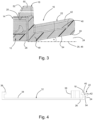
- Fig. 3 further illustrates that the latch 18 has a hook portion 50 which is adapted to snap into the recess 20 of the medical module 14.
- the hook portion 50 is provided with an inlet chamfer 52 which guides the medical module 14 when introduced into the shown locking position.
- the inlet chamfer 52 is arranged at an acute angle with respect to the bottom side 26 of the mounting plate 12.
- the latch 18 can be tilted outward (to the right in fig. 3 ) by actuation of the release flap 22 so as to disengage from the recess 20 in a release position.
- the distance of the connecting portion 48 of the flap 22 to the plane 46 should be smaller than the distance of the outer portion 44 to said plane 46.
- This can be realized arranging the flat bottom side 54 of the flap 22 under an acute angle ⁇ with respect to the skin 28 or plane 46.
- said angle ⁇ is above 5°, e.g. around 10°.
- release flap 22 which in this case on its bottom side runs at a distance parallel to the bottom side 26 of the mounting plate 12, thus maintain a free space with a constant clearance 24.
- the release flap 22 may be directly attached to the upstanding section of the latch 18.
Landscapes
- Health & Medical Sciences (AREA)
- Life Sciences & Earth Sciences (AREA)
- Veterinary Medicine (AREA)
- Engineering & Computer Science (AREA)
- Biomedical Technology (AREA)
- Heart & Thoracic Surgery (AREA)
- Public Health (AREA)
- Animal Behavior & Ethology (AREA)
- General Health & Medical Sciences (AREA)
- Hematology (AREA)
- Anesthesiology (AREA)
- Vascular Medicine (AREA)
- Physics & Mathematics (AREA)
- Surgery (AREA)
- Molecular Biology (AREA)
- Medical Informatics (AREA)
- Pathology (AREA)
- Biophysics (AREA)
- Dermatology (AREA)
- Optics & Photonics (AREA)
- Diabetes (AREA)
- Infusion, Injection, And Reservoir Apparatuses (AREA)
- Media Introduction/Drainage Providing Device (AREA)
Description
- The invention relates to a skin-mountable medical device comprising a mounting plate having a bottom side attachable to the skin of a user preferably via an adhesive pad, a medical module, in particular an analyte sensing device or a drug administration pump, and a snap connector adapted to releasably attach the medical module on the upper side of the mounting plate opposite to the bottom side.
- Such medical device is known from
WO 2009/125398 A2 . There, the device comprises a skin-adherable cradle unit and a fluid dispensing unit, wherein the cradle unit has two latches and the dispensing unit is snap-fitted by operation of thelatches WO 2009/125398 A2 fails to disclose details for user handling of the latches, and the latches appear susceptible to breakage upon insertion of the dispensing unit. Such breaking connections may lead to a loss of the medical device, which may even go unnoticed by the patient.US9248232 US2017224912 also describe prior art medical devices. - On this basis, the object of the invention is to further improve the known medical devices and to provide an easy-to-use design which simplifies user manipulation while avoiding assembly failures.
- The combination of features stated in the independent claim is proposed to achieve this object. Advantageous embodiments and further developments of the invention are derived from the dependent claims.
- The invention is based on the idea of improving user interaction by avoiding interfering contours or contact in the mechanical movement paths. Accordingly, it is proposed that wherein the snap connector has a release flap that can be actuated or pushed by the user to detach the medical module, wherein the release flap projects outwardly from the mounting plate and has an outer portion which at its bottom side maintains a clearance to avoid an interfering skin contact when used or pressed. In this way, the release flap is allowed to move prior to a skin contact, and the user is prevented from applying excessive forces against a skin abutment which may lead to material failure. Moreover, the effort and force for insertion of the medical module is reduced, as no movable part of the snap connector comes into skin contact, thus also avoiding a bending or deformation of the mounting plate. As a result, the user-device-interaction is improved, and the intended medical success is further supported.
- Advantageously, where the bottom side of the mounting plate lies in a plane or is generally planar, the outer portion of the release flap should be arranged at a clearance distance of at least 2 mm, preferably at least 5 mm above this plane. In this way, there is provided sufficient tolerance for unimpeded movement of the flap.
- In another advantageous configuration, where the release flap has an inner portion connected to the mounting plate, the distance of the inner portion to a plane which is defined by the bottom side of the mounting plate (or, in use, by the skin) should be smaller than the distance of the outer portion to said plane.
- In this connection it is further advantageous when the bottom sides of the mounting plate and of the release flap each define a plane, and wherein said planes include an acute angle.
- Preferably, said acute angle is at least 5°, preferably at least 10°.
- In another advantageous embodiment, the bottom side of the release flap runs parallel to the bottom side of the mounting plate. In such a parallel configuration, the release flap may be directly attached to an upstanding part of a latch of the snap connector.
- A particular advantageous embodiment further comprises that the release flap has an upstanding circumferential rim which in use faces away from the skin. Thereby, the user receives a haptic feedback when pressing his finger against the flap. Furthermore, the rim facing upwards avoids unintended slipping of the finger and thereby supports higher pressing forces.
- According to the invention, the snap connector has a latch that is connected to the mounting plate and engages with the medical module in a locking position, wherein the latch can be tilted outward by actuation of the release flap so as to disengage from the medical module in a release position.
- For providing a mechanically secure connection, the latch has a hook portion which is adapted to snap into a recess of the medical module.
- In order to support the application of the medical module onto the mounting plate, the snap connector has an inlet chamfer which is construed to guide the medical module into a locking position, wherein the inlet chamfer is arranged at an acute angle with respect to the bottom side of the mounting plate. Another possibility for facilitating handling and improving joining provides that a securing bracket is provided for attaching the medical module, wherein the securing bracket and the snap connector are arranged at opposite ends of the mounting plate.
- In still another advantageous configuration, the mounting plate and the release flap are formed as an integral, preferably injection-moulded plastic part.
- The medical device according to any of claims 1 to 12, In an advantageous configuration for drug administration, a fitting can be arranged on the bottom plate to provide a skin access preferably for a cannula assembly of the medical module.
- In the following, the invention is further elucidated on the basis of embodiment examples shown schematically in the drawings, where
- Fig. 1
- is a perspective view of a body-wearable medical device including a mounting base with an improved release mechanism;
- Fig. 2
- is a perspective view of the medical device of
fig. 1 ; - Fig. 3
- is an enlarged view of the release mechanism of the medical device; and
- Fig. 4
- is a side view of the mounting base with a further embodiment of the release mechanism.
- Referring to
fig. 1 , amedical device 10 comprises a mounting base orplate 12, amedical module 14 in the form of a body-worn patch pump for administration of insulin and a release mechanism formed as asnap connector 16 which is adapted to releasably attach themedical module 14 on themounting plate 12 e.g. for first time assembly or removal in case of temporarily non-use or replacement. For this purpose, thesnap connector 16 comprises alatch 18 that engages with a recess ornotch 20 in a sidewall of themedical module 14 and a release tap orflap 22 that can be pushed down by the user or patient into a bottom free space orclearance 24 such that theflap 22 is allowed to move prior to a skin contact. - The
mounting plate 12 has abottom side 26 which is attachable at an infusion site to theskin 28 of the user via a self-adhesive pad 30 which is protected on its adhesive side by a peel-off foil 32. - As can be seen best in
fig. 2 , themounting plate 12 has a top orupper side 34 which in use faces away from theskin 28 and supports themedical module 14. Thelatch 18 and a securing hook orbracket 36 are provided at opposite ends of theoblong mounting plate 12 as upstanding elements on theupper side 34. An upstanding hollow fitting orsocket 38 provides skin access for a cannula assembly (not shown). - At the joining area of the
latch 18, theflap 22 is moulded onto the edge of themounting plate 12, such that it projects outwardly and is tilted upwards away from theskin 28, as will be explained in more detail below. Advantageously, theflap 22 has aflat base portion 40 and an upstandingcircumferential rim 42 on the free outer edge of the base portion facing away from theskin 28. - The
mounting plate 12 including its attached elements, 18,22,36,38 may be formed as an integral one-piece plastic part, e.g. by injection-moulding. - As further illustrated in
fig. 3 , theouter portion 44 of therelease flap 22 maintains at itsbottom side clearance 24, such that therelease flap 22 is allowed to move under a force implied by finger pressure without interference, thus avoiding contact to theskin 28 or the self-adhesive pad 30 arranged thereupon. Then, the outer clearance distance to a plane 46 defined by the skin 28 (or, coinciding therewith, defined by theflat bottom side 26 of the mounting plate 12) should be about 5 mm, when viewed in direction perpendicular to the plane 46. -
Fig. 3 further illustrates that thelatch 18 has ahook portion 50 which is adapted to snap into therecess 20 of themedical module 14. Thehook portion 50 is provided with aninlet chamfer 52 which guides themedical module 14 when introduced into the shown locking position. For this purpose, theinlet chamfer 52 is arranged at an acute angle with respect to thebottom side 26 of themounting plate 12. For removal of themedical module 14, thelatch 18 can be tilted outward (to the right infig. 3 ) by actuation of therelease flap 22 so as to disengage from therecess 20 in a release position. - In the embodiment of
fig. 3 , in order to allow a movement prior to an interfering skin contact, the distance of the connectingportion 48 of theflap 22 to the plane 46 should be smaller than the distance of theouter portion 44 to said plane 46. This can be realized arranging theflat bottom side 54 of theflap 22 under an acute angle α with respect to theskin 28 or plane 46. Preferably, said angle α is above 5°, e.g. around 10°. - In the embodiment of
fig. 4 , similar parts are indicated with similar reference signs as explained above. The main difference is in the arrangement of therelease flap 22, which in this case on its bottom side runs at a distance parallel to thebottom side 26 of themounting plate 12, thus maintain a free space with aconstant clearance 24. In this configuration, therelease flap 22 may be directly attached to the upstanding section of thelatch 18.
Claims (12)
- Skin-mountable medical device comprising:a mounting plate (12) having a bottom side (26) attachable to the skin of a user preferably via an adhesive pad (30),a medical module (14), in particular an analyte sensing device or a drug administration pump,a snap connector (16) adapted to releasably attach the medical module (14) on the upper side (34) of the mounting plate (12) opposite to the bottom side (26), wherein the snap connector (16) has a latch (18) that is connected to the mounting plate (12) and engages with the medical module (14) in a locking position, wherein the snap connector (16) has a release flap (22) that can be actuated by the user to detach the medical module (14),wherein the latch (18) can be tilted outward by actuation of the release flap (22) so as to disengage from the medical module (14) in a release position, and wherein the release flap (22) projects outwardly from the mounting plate (12),characterized in that the release flap (22) has an outer portion (44) which at its bottom side (54) maintains a clearance (24) to avoid an interfering contact in use.
- The medical device of claim 1, wherein the bottom side (54) of the mounting plate (12) lies in a plane (46), and the outer portion (44) of the release flap (22) is arranged at a clearance distance of at least 2 mm, preferably at least 5 mm above the plane (46).
- The medical device of claim 1 or 2, wherein the release flap (22) has an inner portion (48) connected to the mounting plate (12), and the distance of the inner portion to a plane (46) which is defined by the bottom side (54) of the mounting plate (12) is smaller than the distance of the outer portion (44) to said plane (46).
- The medical device according to any of claims 1 to 3, wherein the bottom sides (26,54) of the mounting plate (12) and of the release flap (22) each define a plane, and wherein said planes (46) include an acute angle (α).
- The medical device of claim 4, wherein said acute angle (α) is at least 5°, preferably at least 10°.
- The medical device of claim 1 or 2, wherein the bottom side (54) of the release flap (22) runs parallel to the bottom side (26) of the mounting plate (12).
- The medical device according to any of claims 1 to 6, wherein the release flap (22) has an upstanding circumferential rim (42) which in use faces away from the skin.
- The medical device according to any of claims 1 to 7, wherein the latch (18) has a hook portion (50) which is adapted to snap into a recess (20) of the medical module (14).
- The medical device according to any of claims 1 to 8, wherein the snap connector (16) has an inlet chamfer (52) which is construed to guide the medical module (14) into a locking position, wherein the inlet chamfer (52) is arranged at an acute angle with respect to the bottom side (26) of the mounting plate (12) .
- The medical device according to any of claims 1 to 8, further comprising a securing bracket (36) for attaching the medical module (14), wherein the securing bracket (36) and the snap connector (16) are arranged at opposite ends of the mounting plate (12).
- The medical device according to any of claims 1 to 10, wherein the mounting plate (12) and the release flap (22) are formed as an integral, preferably injection-moulded plastic part.
- The medical device according to any of claims 1 to 11, further comprising a fitting (38) arranged on the bottom plate to provide a skin access preferably for a cannula assembly of the medical module (14).
Priority Applications (14)
| Application Number | Priority Date | Filing Date | Title |
|---|---|---|---|
| ES18215163T ES2962854T3 (en) | 2018-12-21 | 2018-12-21 | Medical device that can be placed on the skin |
| EP18215163.9A EP3669906B1 (en) | 2018-12-21 | 2018-12-21 | Skin-mountable medical device |
| HUE18215163A HUE063930T2 (en) | 2018-12-21 | 2018-12-21 | A medical device that can be applied to the skin |
| CA3123330A CA3123330A1 (en) | 2018-12-21 | 2019-12-17 | Skin-mountable medical device |
| CN201980084709.5A CN113164677A (en) | 2018-12-21 | 2019-12-17 | Skin mountable medical device |
| SG11202106667YA SG11202106667YA (en) | 2018-12-21 | 2019-12-17 | Skin-mountable medical device |
| IL284143A IL284143B2 (en) | 2018-12-21 | 2019-12-17 | A medical device that can be worn on the skin |
| MX2021007578A MX2021007578A (en) | 2018-12-21 | 2019-12-17 | Skin-mountable medical device. |
| AU2019409541A AU2019409541A1 (en) | 2018-12-21 | 2019-12-17 | Skin-mountable medical device |
| JP2021535572A JP7515482B2 (en) | 2018-12-21 | 2019-12-17 | Skin-mountable medical devices |
| PCT/EP2019/085524 WO2020127181A1 (en) | 2018-12-21 | 2019-12-17 | Skin-mountable medical device |
| BR112021011881-0A BR112021011881A2 (en) | 2018-12-21 | 2019-12-17 | SKIN MOUNTABLE MEDICAL DEVICE |
| KR1020217018593A KR102888540B1 (en) | 2018-12-21 | 2020-01-17 | Skin-mountable medical devices |
| US17/351,700 US12544505B2 (en) | 2018-12-21 | 2021-06-18 | Skin-mountable medical device |
Applications Claiming Priority (1)
| Application Number | Priority Date | Filing Date | Title |
|---|---|---|---|
| EP18215163.9A EP3669906B1 (en) | 2018-12-21 | 2018-12-21 | Skin-mountable medical device |
Publications (3)
| Publication Number | Publication Date |
|---|---|
| EP3669906A1 EP3669906A1 (en) | 2020-06-24 |
| EP3669906B1 true EP3669906B1 (en) | 2023-09-20 |
| EP3669906C0 EP3669906C0 (en) | 2023-09-20 |
Family
ID=64755433
Family Applications (1)
| Application Number | Title | Priority Date | Filing Date |
|---|---|---|---|
| EP18215163.9A Active EP3669906B1 (en) | 2018-12-21 | 2018-12-21 | Skin-mountable medical device |
Country Status (14)
| Country | Link |
|---|---|
| US (1) | US12544505B2 (en) |
| EP (1) | EP3669906B1 (en) |
| JP (1) | JP7515482B2 (en) |
| KR (1) | KR102888540B1 (en) |
| CN (1) | CN113164677A (en) |
| AU (1) | AU2019409541A1 (en) |
| BR (1) | BR112021011881A2 (en) |
| CA (1) | CA3123330A1 (en) |
| ES (1) | ES2962854T3 (en) |
| HU (1) | HUE063930T2 (en) |
| IL (1) | IL284143B2 (en) |
| MX (1) | MX2021007578A (en) |
| SG (1) | SG11202106667YA (en) |
| WO (1) | WO2020127181A1 (en) |
Families Citing this family (6)
| Publication number | Priority date | Publication date | Assignee | Title |
|---|---|---|---|---|
| PT1762259E (en) | 2005-09-12 | 2010-12-10 | Unomedical As | INSERTER FOR AN INFUSION ASSEMBLY WITH A FIRST AND SECOND SPRING UNITS |
| US10194938B2 (en) | 2011-03-14 | 2019-02-05 | UnoMedical, AS | Inserter system with transport protection |
| CN113950341B (en) | 2019-05-20 | 2024-03-19 | 优诺医疗有限公司 | Rotatable infusion device and method |
| US20230119615A1 (en) * | 2020-04-14 | 2023-04-20 | Shl Medical Ag | Pad for adhering a medicament delivery device to the skin, including a needle |
| WO2022147985A1 (en) * | 2021-01-05 | 2022-07-14 | Medtrum Technologies Inc. | A skin patch drug infusion device |
| JP7588537B2 (en) * | 2021-03-25 | 2024-11-22 | テルモ株式会社 | Drug administration device |
Family Cites Families (11)
| Publication number | Priority date | Publication date | Assignee | Title |
|---|---|---|---|---|
| DE19821723C2 (en) * | 1998-05-14 | 2000-07-06 | Disetronic Licensing Ag | Catheter head for subcutaneous administration of an active ingredient |
| CN101355976B (en) | 2005-12-23 | 2011-01-26 | 优诺医疗有限公司 | Device for injection |
| DK3632488T3 (en) * | 2006-12-22 | 2023-06-06 | Hoffmann La Roche | Device for continuous administration of a therapeutic fluid |
| US8002752B2 (en) * | 2007-06-25 | 2011-08-23 | Medingo, Ltd. | Protector apparatus |
| AU2009235064A1 (en) | 2008-04-09 | 2009-10-15 | F.Hoffmann-La Roche Ag | Modular skin-adherable system for medical fluid delivery |
| WO2009139857A1 (en) | 2008-05-14 | 2009-11-19 | Becton, Dickinson & Company | Separatable infusion set with cleanable interface and straight line attachment |
| EP2506914B1 (en) * | 2009-11-30 | 2018-10-17 | Roche Diabetes Care GmbH | Analyte monitoring and fluid dispensing system |
| US9381300B2 (en) | 2010-09-24 | 2016-07-05 | Perqflo, Llc | Infusion pumps |
| US8882711B2 (en) | 2011-09-30 | 2014-11-11 | Animas Corporation | Insertion device for a medical conduit |
| PL3097933T3 (en) | 2015-05-26 | 2020-03-31 | F. Hoffmann-La Roche Ag | Cartridge and inserter for a medical system |
| US11050453B2 (en) * | 2019-04-25 | 2021-06-29 | Aatc, Llc | Smart phone holder |
-
2018
- 2018-12-21 EP EP18215163.9A patent/EP3669906B1/en active Active
- 2018-12-21 ES ES18215163T patent/ES2962854T3/en active Active
- 2018-12-21 HU HUE18215163A patent/HUE063930T2/en unknown
-
2019
- 2019-12-17 AU AU2019409541A patent/AU2019409541A1/en not_active Abandoned
- 2019-12-17 CN CN201980084709.5A patent/CN113164677A/en active Pending
- 2019-12-17 IL IL284143A patent/IL284143B2/en unknown
- 2019-12-17 MX MX2021007578A patent/MX2021007578A/en unknown
- 2019-12-17 CA CA3123330A patent/CA3123330A1/en active Pending
- 2019-12-17 JP JP2021535572A patent/JP7515482B2/en active Active
- 2019-12-17 BR BR112021011881-0A patent/BR112021011881A2/en active Search and Examination
- 2019-12-17 SG SG11202106667YA patent/SG11202106667YA/en unknown
- 2019-12-17 WO PCT/EP2019/085524 patent/WO2020127181A1/en not_active Ceased
-
2020
- 2020-01-17 KR KR1020217018593A patent/KR102888540B1/en active Active
-
2021
- 2021-06-18 US US17/351,700 patent/US12544505B2/en active Active
Also Published As
| Publication number | Publication date |
|---|---|
| KR20220118293A (en) | 2022-08-25 |
| HUE063930T2 (en) | 2024-02-28 |
| JP7515482B2 (en) | 2024-07-12 |
| ES2962854T3 (en) | 2024-03-21 |
| SG11202106667YA (en) | 2021-07-29 |
| IL284143B1 (en) | 2025-07-01 |
| CN113164677A (en) | 2021-07-23 |
| BR112021011881A2 (en) | 2021-08-31 |
| US20210308370A1 (en) | 2021-10-07 |
| MX2021007578A (en) | 2021-08-11 |
| KR102888540B1 (en) | 2025-11-19 |
| WO2020127181A1 (en) | 2020-06-25 |
| US12544505B2 (en) | 2026-02-10 |
| EP3669906A1 (en) | 2020-06-24 |
| JP2022513522A (en) | 2022-02-08 |
| IL284143A (en) | 2021-08-31 |
| AU2019409541A1 (en) | 2021-06-17 |
| EP3669906C0 (en) | 2023-09-20 |
| CA3123330A1 (en) | 2020-06-25 |
| IL284143B2 (en) | 2025-11-01 |
Similar Documents
| Publication | Publication Date | Title |
|---|---|---|
| EP3669906B1 (en) | Skin-mountable medical device | |
| US11786650B2 (en) | Assemblies and methods for infusion pump system administration sets | |
| US20250176863A1 (en) | Analyte sensor devices, connections, and methods | |
| US11607488B2 (en) | Infusion device with automatic insertion and introducer needle retraction | |
| US8657791B2 (en) | Catheter securement device | |
| KR20240017396A (en) | injection support pad | |
| CN107050567A (en) | Anti- acupuncture remaining needle | |
| WO2017038483A1 (en) | Syringe pump | |
| EP2528469B1 (en) | Module retainer | |
| HK40048603A (en) | Skin-mountable medical device | |
| RU2812201C2 (en) | Medical device attached to skin | |
| EP2277581A1 (en) | A device for fastening and protecting a catheter unit | |
| CN217548694U (en) | Injection pump | |
| CN114588393B (en) | Indwelling type infusion assembly | |
| US12582334B2 (en) | Analyte sensor devices, connections, and methods | |
| JP4361959B2 (en) | Container / Syringe | |
| CN111317887B (en) | Remaining needle protection piece, medicine storage device needle head protection piece and needle head protection assembly | |
| CN115868974A (en) | Medical equipment and medical auxiliary device | |
| EP4197573A1 (en) | Winged needle assembly, packaging material for winged needle assembly, cap for winged needle assembly, and winged needle assembly set | |
| CN205832324U (en) | Micropump Syringe Display Device |
Legal Events
| Date | Code | Title | Description |
|---|---|---|---|
| PUAI | Public reference made under article 153(3) epc to a published international application that has entered the european phase |
Free format text: ORIGINAL CODE: 0009012 |
|
| STAA | Information on the status of an ep patent application or granted ep patent |
Free format text: STATUS: THE APPLICATION HAS BEEN PUBLISHED |
|
| AK | Designated contracting states |
Kind code of ref document: A1 Designated state(s): AL AT BE BG CH CY CZ DE DK EE ES FI FR GB GR HR HU IE IS IT LI LT LU LV MC MK MT NL NO PL PT RO RS SE SI SK SM TR |
|
| AX | Request for extension of the european patent |
Extension state: BA ME |
|
| STAA | Information on the status of an ep patent application or granted ep patent |
Free format text: STATUS: REQUEST FOR EXAMINATION WAS MADE |
|
| 17P | Request for examination filed |
Effective date: 20201219 |
|
| RBV | Designated contracting states (corrected) |
Designated state(s): AL AT BE BG CH CY CZ DE DK EE ES FI FR GB GR HR HU IE IS IT LI LT LU LV MC MK MT NL NO PL PT RO RS SE SI SK SM TR |
|
| GRAP | Despatch of communication of intention to grant a patent |
Free format text: ORIGINAL CODE: EPIDOSNIGR1 |
|
| STAA | Information on the status of an ep patent application or granted ep patent |
Free format text: STATUS: GRANT OF PATENT IS INTENDED |
|
| RIC1 | Information provided on ipc code assigned before grant |
Ipc: A61M 5/14 20060101ALI20230327BHEP Ipc: A61M 5/142 20060101AFI20230327BHEP |
|
| INTG | Intention to grant announced |
Effective date: 20230414 |
|
| GRAS | Grant fee paid |
Free format text: ORIGINAL CODE: EPIDOSNIGR3 |
|
| GRAA | (expected) grant |
Free format text: ORIGINAL CODE: 0009210 |
|
| STAA | Information on the status of an ep patent application or granted ep patent |
Free format text: STATUS: THE PATENT HAS BEEN GRANTED |
|
| AK | Designated contracting states |
Kind code of ref document: B1 Designated state(s): AL AT BE BG CH CY CZ DE DK EE ES FI FR GB GR HR HU IE IS IT LI LT LU LV MC MK MT NL NO PL PT RO RS SE SI SK SM TR |
|
| RAP3 | Party data changed (applicant data changed or rights of an application transferred) |
Owner name: F. HOFFMANN-LA ROCHE AG Owner name: ROCHE DIABETES CARE GMBH |
|
| REG | Reference to a national code |
Ref country code: GB Ref legal event code: FG4D |
|
| REG | Reference to a national code |
Ref country code: CH Ref legal event code: EP |
|
| REG | Reference to a national code |
Ref country code: IE Ref legal event code: FG4D |
|
| REG | Reference to a national code |
Ref country code: DE Ref legal event code: R096 Ref document number: 602018057850 Country of ref document: DE |
|
| U01 | Request for unitary effect filed |
Effective date: 20231006 |
|
| U07 | Unitary effect registered |
Designated state(s): AT BE BG DE DK EE FI FR IT LT LU LV MT NL PT SE SI Effective date: 20231017 |
|
| U20 | Renewal fee for the european patent with unitary effect paid |
Year of fee payment: 6 Effective date: 20231121 |
|
| PG25 | Lapsed in a contracting state [announced via postgrant information from national office to epo] |
Ref country code: GR Free format text: LAPSE BECAUSE OF FAILURE TO SUBMIT A TRANSLATION OF THE DESCRIPTION OR TO PAY THE FEE WITHIN THE PRESCRIBED TIME-LIMIT Effective date: 20231221 |
|
| PG25 | Lapsed in a contracting state [announced via postgrant information from national office to epo] |
Ref country code: RS Free format text: LAPSE BECAUSE OF FAILURE TO SUBMIT A TRANSLATION OF THE DESCRIPTION OR TO PAY THE FEE WITHIN THE PRESCRIBED TIME-LIMIT Effective date: 20230920 Ref country code: NO Free format text: LAPSE BECAUSE OF FAILURE TO SUBMIT A TRANSLATION OF THE DESCRIPTION OR TO PAY THE FEE WITHIN THE PRESCRIBED TIME-LIMIT Effective date: 20231220 Ref country code: HR Free format text: LAPSE BECAUSE OF FAILURE TO SUBMIT A TRANSLATION OF THE DESCRIPTION OR TO PAY THE FEE WITHIN THE PRESCRIBED TIME-LIMIT Effective date: 20230920 Ref country code: GR Free format text: LAPSE BECAUSE OF FAILURE TO SUBMIT A TRANSLATION OF THE DESCRIPTION OR TO PAY THE FEE WITHIN THE PRESCRIBED TIME-LIMIT Effective date: 20231221 |
|
| REG | Reference to a national code |
Ref country code: HU Ref legal event code: AG4A Ref document number: E063930 Country of ref document: HU |
|
| REG | Reference to a national code |
Ref country code: ES Ref legal event code: FG2A Ref document number: 2962854 Country of ref document: ES Kind code of ref document: T3 Effective date: 20240321 |
|
| PG25 | Lapsed in a contracting state [announced via postgrant information from national office to epo] |
Ref country code: IS Free format text: LAPSE BECAUSE OF FAILURE TO SUBMIT A TRANSLATION OF THE DESCRIPTION OR TO PAY THE FEE WITHIN THE PRESCRIBED TIME-LIMIT Effective date: 20240120 |
|
| PG25 | Lapsed in a contracting state [announced via postgrant information from national office to epo] |
Ref country code: SM Free format text: LAPSE BECAUSE OF FAILURE TO SUBMIT A TRANSLATION OF THE DESCRIPTION OR TO PAY THE FEE WITHIN THE PRESCRIBED TIME-LIMIT Effective date: 20230920 Ref country code: RO Free format text: LAPSE BECAUSE OF FAILURE TO SUBMIT A TRANSLATION OF THE DESCRIPTION OR TO PAY THE FEE WITHIN THE PRESCRIBED TIME-LIMIT Effective date: 20230920 Ref country code: IS Free format text: LAPSE BECAUSE OF FAILURE TO SUBMIT A TRANSLATION OF THE DESCRIPTION OR TO PAY THE FEE WITHIN THE PRESCRIBED TIME-LIMIT Effective date: 20240120 Ref country code: CZ Free format text: LAPSE BECAUSE OF FAILURE TO SUBMIT A TRANSLATION OF THE DESCRIPTION OR TO PAY THE FEE WITHIN THE PRESCRIBED TIME-LIMIT Effective date: 20230920 Ref country code: SK Free format text: LAPSE BECAUSE OF FAILURE TO SUBMIT A TRANSLATION OF THE DESCRIPTION OR TO PAY THE FEE WITHIN THE PRESCRIBED TIME-LIMIT Effective date: 20230920 |
|
| PG25 | Lapsed in a contracting state [announced via postgrant information from national office to epo] |
Ref country code: PL Free format text: LAPSE BECAUSE OF FAILURE TO SUBMIT A TRANSLATION OF THE DESCRIPTION OR TO PAY THE FEE WITHIN THE PRESCRIBED TIME-LIMIT Effective date: 20230920 |
|
| REG | Reference to a national code |
Ref country code: DE Ref legal event code: R097 Ref document number: 602018057850 Country of ref document: DE |
|
| PLBE | No opposition filed within time limit |
Free format text: ORIGINAL CODE: 0009261 |
|
| STAA | Information on the status of an ep patent application or granted ep patent |
Free format text: STATUS: NO OPPOSITION FILED WITHIN TIME LIMIT |
|
| PG25 | Lapsed in a contracting state [announced via postgrant information from national office to epo] |
Ref country code: MC Free format text: LAPSE BECAUSE OF FAILURE TO SUBMIT A TRANSLATION OF THE DESCRIPTION OR TO PAY THE FEE WITHIN THE PRESCRIBED TIME-LIMIT Effective date: 20230920 |
|
| 26N | No opposition filed |
Effective date: 20240621 |
|
| PG25 | Lapsed in a contracting state [announced via postgrant information from national office to epo] |
Ref country code: MC Free format text: LAPSE BECAUSE OF FAILURE TO SUBMIT A TRANSLATION OF THE DESCRIPTION OR TO PAY THE FEE WITHIN THE PRESCRIBED TIME-LIMIT Effective date: 20230920 |
|
| U20 | Renewal fee for the european patent with unitary effect paid |
Year of fee payment: 7 Effective date: 20241121 |
|
| PGFP | Annual fee paid to national office [announced via postgrant information from national office to epo] |
Ref country code: ES Payment date: 20250102 Year of fee payment: 7 |
|
| PGFP | Annual fee paid to national office [announced via postgrant information from national office to epo] |
Ref country code: CH Payment date: 20250101 Year of fee payment: 7 |
|
| PG25 | Lapsed in a contracting state [announced via postgrant information from national office to epo] |
Ref country code: CY Free format text: LAPSE BECAUSE OF FAILURE TO SUBMIT A TRANSLATION OF THE DESCRIPTION OR TO PAY THE FEE WITHIN THE PRESCRIBED TIME-LIMIT; INVALID AB INITIO Effective date: 20181221 |
|
| PG25 | Lapsed in a contracting state [announced via postgrant information from national office to epo] |
Ref country code: TR Free format text: LAPSE BECAUSE OF FAILURE TO SUBMIT A TRANSLATION OF THE DESCRIPTION OR TO PAY THE FEE WITHIN THE PRESCRIBED TIME-LIMIT Effective date: 20230920 |
|
| U20 | Renewal fee for the european patent with unitary effect paid |
Year of fee payment: 8 Effective date: 20251119 |
|
| REG | Reference to a national code |
Ref country code: CH Ref legal event code: U11 Free format text: ST27 STATUS EVENT CODE: U-0-0-U10-U11 (AS PROVIDED BY THE NATIONAL OFFICE) Effective date: 20260101 |
|
| PGFP | Annual fee paid to national office [announced via postgrant information from national office to epo] |
Ref country code: GB Payment date: 20251120 Year of fee payment: 8 |
|
| PGFP | Annual fee paid to national office [announced via postgrant information from national office to epo] |
Ref country code: HU Payment date: 20251212 Year of fee payment: 8 |
|
| PGFP | Annual fee paid to national office [announced via postgrant information from national office to epo] |
Ref country code: IE Payment date: 20251121 Year of fee payment: 8 |