EP3097761A1 - Two sided cleaning arrangements for endless belt - Google Patents
Two sided cleaning arrangements for endless belt Download PDFInfo
- Publication number
- EP3097761A1 EP3097761A1 EP16169885.7A EP16169885A EP3097761A1 EP 3097761 A1 EP3097761 A1 EP 3097761A1 EP 16169885 A EP16169885 A EP 16169885A EP 3097761 A1 EP3097761 A1 EP 3097761A1
- Authority
- EP
- European Patent Office
- Prior art keywords
- cleaning
- crop
- carrying surface
- endless belt
- feature
- Prior art date
- Legal status (The legal status is an assumption and is not a legal conclusion. Google has not performed a legal analysis and makes no representation as to the accuracy of the status listed.)
- Granted
Links
Images


Classifications
-
- A—HUMAN NECESSITIES
- A01—AGRICULTURE; FORESTRY; ANIMAL HUSBANDRY; HUNTING; TRAPPING; FISHING
- A01D—HARVESTING; MOWING
- A01D61/00—Elevators or conveyors for binders or combines
- A01D61/02—Endless belts
-
- A—HUMAN NECESSITIES
- A01—AGRICULTURE; FORESTRY; ANIMAL HUSBANDRY; HUNTING; TRAPPING; FISHING
- A01D—HARVESTING; MOWING
- A01D34/00—Mowers; Mowing apparatus of harvesters
- A01D34/01—Mowers; Mowing apparatus of harvesters characterised by features relating to the type of cutting apparatus
- A01D34/02—Mowers; Mowing apparatus of harvesters characterised by features relating to the type of cutting apparatus having reciprocating cutters
-
- A—HUMAN NECESSITIES
- A01—AGRICULTURE; FORESTRY; ANIMAL HUSBANDRY; HUNTING; TRAPPING; FISHING
- A01D—HARVESTING; MOWING
- A01D41/00—Combines, i.e. harvesters or mowers combined with threshing devices
- A01D41/12—Details of combines
- A01D41/14—Mowing tables
-
- A—HUMAN NECESSITIES
- A01—AGRICULTURE; FORESTRY; ANIMAL HUSBANDRY; HUNTING; TRAPPING; FISHING
- A01D—HARVESTING; MOWING
- A01D57/00—Delivering mechanisms for harvesters or mowers
- A01D57/20—Delivering mechanisms for harvesters or mowers with conveyor belts
-
- A—HUMAN NECESSITIES
- A01—AGRICULTURE; FORESTRY; ANIMAL HUSBANDRY; HUNTING; TRAPPING; FISHING
- A01D—HARVESTING; MOWING
- A01D61/00—Elevators or conveyors for binders or combines
- A01D61/002—Elevators or conveyors for binders or combines transversal conveying devices
-
- B—PERFORMING OPERATIONS; TRANSPORTING
- B65—CONVEYING; PACKING; STORING; HANDLING THIN OR FILAMENTARY MATERIAL
- B65G—TRANSPORT OR STORAGE DEVICES, e.g. CONVEYORS FOR LOADING OR TIPPING, SHOP CONVEYOR SYSTEMS OR PNEUMATIC TUBE CONVEYORS
- B65G45/00—Lubricating, cleaning, or clearing devices
- B65G45/10—Cleaning devices
Definitions
- This disclosure relates to draper headers, and more particularly to cleaning arrangements for belts of draper headers.
- Agricultural harvesters use a variety of implements attached to their front ends to gather crops.
- One type of these implements is called a “draper” or a “draper header”.
- Conventional draper headers use conveyors with endless belts to carry cut crop material from leading-edge knives to center regions of the headers. From there, the cut crop material is conveyed into the harvesters. Once in the harvester, the cut crop material is further processed by separating grain from unwanted crop material (typically called “material other than grain” or "MOG").
- crop material can become lodged in various spaces on and around the belts, resulting in sub-optimal performance of the header.
- some headers include crop ramps that extend rearwardly (from a frame of reference of the relevant vehicle) from the knives over the leading edge of the headers' endless belts. These crop ramps help to lift the cut crop material onto the endless belts for transport along the header.
- crop material can become lodged in gaps between the crop ramps and the endless belts, to the detriment of header performance. Crop material can also become lodged in, and pass through, other gaps along the belts. In some cases, this can require machine stoppage in order to clear crop material from the headers' internal areas.
- a two-sided cleaning arrangement is disclosed for endless belts, such as endless belts of draper headers.
- an endless belt for a header with a crop ramp and a trailing cover may include a crop-carrying surface and first and second cleaning regions that are at least partly separated from each other by the crop-carrying surface.
- the cleaning regions may include respective cleaning features that extend above or are recessed below the crop-carrying surface, in order to clean crop material from below the crop ramp and the trailing cover, respectively.
- an endless belt for a header with a crop ramp and a trailing cover may include a crop-carrying surface extending at least partly between the crop ramp and the trailing cover.
- the endless belt may also include first and second cleaning regions at least partly separated from each other by the crop-carrying surface.
- the cleaning regions may include respective arrays of cleaning features with respective pluralities of alternating ridges and recesses.
- an endless belt may include first and second cleaning features disposed in first and second edge regions, respectively, of the endless belt. At least part of each cleaning surface may extend above or be recessed below a crop-carrying surface of the belt.
- the term “forward” corresponds to a forward direction of travel of the belt, with respect to a supporting frame (e.g., a frame of a draper header), during normal operation of the belt.
- the term “rearward” corresponds to a direction opposite the forward direction of travel of the belt.
- a "forward facing" feature on an endless belt may generally face in the direction that the belt travels during normal operation, while a “rearward facing” feature may generally face opposite that direction.
- the term “leading” indicates a direction of travel of the header during normal operation (e.g., the forward direction of travel of a harvester vehicle carrying the header).
- the term “trailing” indicates a direction that is opposite the leading direction.
- a "leading" edge of a knife assembly of a draper header may be generally disposed at the front of the knife assembly, with respect to the direction travel of the draper header during normal operation (e.g., as carried by a harvester vehicle).
- a “trailing” edge of the knife assembly may be generally disposed at the back of the knife assembly, with respect to the direction of travel of the draper header during normal operation.
- leading and trailing may not necessarily denote the extreme leading or trailing edge of a body.
- a trailing cover on an agricultural header may trail behind certain features, such as a leading-edge knife or endless belt, but may not necessarily be at the trailing end of the entire header.
- an endless belt may be configured to be reversed on a conveyor, such that a particular edge of the belt may be either a leading edge or a trailing edge, depending on the orientation of the belt.
- leading and trailing may be used herein with respect to reversible endless belts (or features thereupon) to indicate a currently-addressed orientation of the belt (or feature), rather than an absolute orientation.
- an endless belt for crop transport may result in crop material becoming lodged in or passing through various clearances, to the detriment of overall header performance.
- cut crop material may be pushed into, and generally lodged within, a clearance between crop ramps of the header and a leading portion of the endless belt.
- crop material may be pushed into, and sometimes pass through, a clearance between a trailing cover (e.g., a back sheet deflector or rear frame cover) and a trailing portion of the endless belt.
- a trailing cover e.g., a back sheet deflector or rear frame cover
- a two-sided cleaning arrangement for an endless belt includes cleaning features on leading and trailing portions of an endless belt.
- a leading portion of the belt near a crop ramp may include a first set of cleaning features
- a trailing portion of the belt near a trailing cover may include a second set of cleaning features.
- such a two-sided configuration may help to remove crop material from a gap between the belt and the crop ramp and from a gap between the belt and the trailing cover.
- the orientation of the belt on the header may be reversed such that the previously trailing (or leading) portion of the belt is oriented as a leading (or trailing) portion of the belt for subsequent operation. Accordingly, the cleaning features on the previously trailing (or leading) portion of the belt may continue to provide cleaning functionality at a leading (or trailing) region, even after relatively significant wear to cleaning features at the other edge of the belt, and the useful life of the belt may be extended.
- Cleaning features according to the present disclosure may exhibit (e.g., be formed in the shape of) a variety of patterns.
- cleaning features may be formed as polygonal or other shapes that are raised away from, or recessed below, a cleaning surface of a belt.
- cleaning features may be formed as rectangles, triangles, chevrons, and so on, which either extend above a cleaning surface of a belt, or are recessed below (i.e., extend below) the cleaning surface.
- a cleaning feature may extend forward (i.e., along the direction of motion of the belt during normal operation) from a trailing end of the feature to a leading end of the feature (or vice versa).
- varying geometries may be used, such that a cleaning feature may include portions configured as rectangles, portions configured as triangles, raised portions, recessed portions, and so on.
- cleaning features on a leading or trailing edge of belt may be arranged within a cleaning region that extends over a substantial portion of the circumferential length of the belt.
- cleaning features may be arranged in various arrays within the cleaning region. For example, a cleaning feature such as a raised rectangle or triangle may be repeated (with or without geometric variation of the rectangle or triangle) in an array that extends along 25% or more (e.g., 50%) of a belt. In this way, cleaning functionality may be provided by the array of cleaning features at multiple points along the belt.
- an array of cleaning features may include different types of cleaning features, such as rectangular ridges and raised triangles.
- an array of cleaning features may include alternating raised and recessed geometries.
- raised cleaning features i.e., cleaning features extending above a cleaning surface of a belt
- raised rectangles or triangles may alternate with recessed cleaning features (i.e., cleaning features extending below the cleaning surface) along a belt.
- such an array of cleaning features may be continuous along the entire circumferential length of the belt.
- one array of cleaning features at a leading or trailing edge of a belt may be separated from another array of cleaning features on the relevant edge by various distances.
- cleaning feature arrays (or individual cleaning features) may be separated from each other by portions of a belt without cleaning features.
- an array of alternating ridges and recesses on a cleaning belt may be separated from another array on the belt by one or more flattened regions on the belt. Such flattened regions may be flush with a crop-carrying surface of the belt, or may extend above or be recessed below the crop-carrying surface. This may allow for variations in cleaning effects along a circumferential length of a belt, and may also facilitate various manufacturing processes.
- a cleaning feature may be aligned with other features on a belt.
- a cleaning feature at a leading or trailing edge of a belt may be generally aligned with a cleat extending over a central portion of the belt.
- cleaning features at a leading edge of a belt may vary in pattern or in disposition (e.g., orientation or order) within an array from cleaning features at a trailing edge of the belt.
- the header 20 includes a frame 22 that supports left- and right-side conveyors 24 and 26 and a center conveyor 28.
- Left- and right-side conveyors 24 and 26 are taken from the perspective of an operator of a trailing agricultural harvester (not shown) carrying the header.
- Each of the conveyors 24, 26, and 28 is configured as a belt-type conveyor extending over a respective circumferential length, with motive devices such as motors, gears, internal belts, and so on (not shown) moving endless belts 30, 32, and 34 in respective loops along the header 20.
- the belts 30, 32, and 34 may be formed from as elastomer-impregnated fabric belts, supported by two or more rollers (not shown). Generally, the belts 30 and 32 may be rotated such that upper surfaces of the belts 30 and 32 move inward along the header 20 in respective directions 36 and 38. In this way, material such as cut plant matter may be moved by the belts 30 and 32 to the center conveyor 28, which may in turn use the belt 34 move the material off of the header 20 and into an associated harvester vehicle (not shown). As depicted, for example, a cylindrical conveyor 40 may be configured receive cut crop material from the center conveyor 28 and carry the crop material rearward (i.e., in a direction 44) through an aperture in the frame 22 and into the harvester (not shown).
- various cleats 42 are fixed to the surface of each of the endless belts 30, 32, and 34, with the cleats 42 generally extending in a direction transverse to the direction of travel of the respective belt 30, 32, or 34.
- the cleat 42 may extend only partly across the respective width of the belts 30, 32, and 34, and may accordingly not extend to the leading edge or the trailing edge of the belts 30, 32, and 34.
- the cleats 42 exhibit a generally trapezoidal cross-section, with curved lower vertices (see FIG. 2A ). In other embodiments, other configurations of the cleats 42 may be possible.
- the header 20 of FIG. 1 includes a reciprocating knife 50 that extends across substantially the entire length of the header 20.
- the header 20 may also include a leading cover arranged between the reciprocating knife 50 and the various belts 30, 32, and 34, with the leading cover extending at least partly over a leading edge of at least the belts 30 and 32.
- the header 20 includes an elongate row of interlocking crop ramp segments 52 (see also FIG. 2A ), that extend along substantially the entire length of the header 20.
- the header 20 also includes a trailing cover 46 (e.g., a back sheet deflector or rear frame cover) separated from the crop ramp segments 52 by a width 48.
- the trailing cover 46 may serve to cover and protect various internal components of the header 20, and may also generally define a trailing end of a crop-carrying region of the header 20.
- the cleats 42 may extend over the entire width 48. In other embodiments, the cleats 42 may extend over only a fraction of the width 48.
- the harvester vehicle may carry the header 20 through an agricultural field in a nominal forward direction 54.
- the reciprocating knife 50 may operate at the leading edge of the header 20 to sever the crops adjacent to the ground, and the cut crop material may fall in a trailing direction (i.e., generally opposite the direction 54), onto one or more of the three conveyors 24, 26, and 28.
- the left side conveyor 24 may then carry the crop material rightward, using the two belts 30, toward the center of the header 20.
- the right side conveyor 26 may carry the crop material leftward, using the two belts 32, toward the center of the header 20, and the center conveyor 28 may carry the crop material rearward toward and underneath the cylindrical conveyor 40.
- Crop material from the conveyor 40 is then moved in the trailing direction through the aperture in the frame 22 of the header 20 and thence into the agricultural harvester (not shown).
- left-side conveyor 24 and the right-side conveyor 26 are similarly configured, although the conveyors 24 and 26 may carry crop material in opposite directions (i.e., for both of the conveyors 24 and 26, toward the center conveyor 28).
- left- and right-side conveyors (or others) may be configured differently.
- description herein of the left-side conveyor 24 may be applicable to the right-side conveyor 26, as well as other conveyors of other embodiments.
- the header 20 may include the crop ramp segments 52a through 52c, each generally disposed adjacent to and overlapping with neighboring instances of the segments 52.
- Each of the crop ramp segments 52 generally extends in the trailing direction from a corresponding leading edge 60 (e.g., leading edges 60a through 60c) to a corresponding trailing edge 62 (e..g, trailing edges 62a through 62c).
- the trailing edges 62 of the crop ramp segments 52 at least partly cover a leading edge of the relevant belt.
- the trailing edges 62a through 62c of the crop ramp segments 52a through 52c cover a leading edge 64 of the belt 30.
- each of the trailing edges 62 may generally define a gap 66 with a clearance 66a between the crop-carrying surface 30a of the belt 30 (or other crop-carrying surfaces of other belts) and the corresponding ramp segment 52.
- the crop ramp segments 52 may include features disposed within the gap 66.
- elongate recesses 68 are formed on the underside of each of the crop ramp segments 52a through 52c.
- the recesses 68 extend at an angle with respect to the belt 30, such that the recesses 68 extend forward, with respect to the direction 36 of belt travel, and in the trailing direction, with respect to the direction 54 of header travel, from the leading ends of the recesses 68 to the trailing ends of the recesses 68.
- other configurations may be used, or other (or no) features may be included on the crop ramp segments 52 within the gap 66.
- the recesses 68 may assist in removing cut crop material from the gap 66, in a manner that is complimentary to the belt cleaning arrangements disclosed herein.
- a leading-edge cleaning feature 70 is included on the belt 30 near the crop ramp segments 52.
- the cleaning feature 70 is configured as a generally rectangular body extending (i.e., raised) above the crop-carrying surface 30a. In other embodiments, other geometries may be used.
- the feature 70 may be integrally formed with the belt 30. In some embodiments, the feature 70 may be separately formed then securely bonded or otherwise attached to the belt 30.
- the feature 70 exhibits a maximum height 72 above the crop-carrying surface 30a that is somewhat less than the total clearance 66a between the ramp segment 52b and the crop-carrying surface 30a. Accordingly, as the belt 30 travels along the direction 36, the feature 70 may sweep crop material out of the gap 66 without substantially interfering with the ramp segment 52b.
- the feature 70 (or another cleaning feature) may exhibit a maximum height that is substantially equal to the clearance 66a, such that the feature 70 directly contacts the underside of the ramp segment 52b.
- the feature 70 (or another cleaning feature) may exhibit a maximum height that is larger than the clearance 66a, such that the feature 70 may bear on the ramp segment 52b and urge the ramp segment 52b upward during operation.
- the feature 70 includes a forward facing surface 70a that is generally perpendicular to the crop-carrying surface 30a, and that tends to engage cut crop material embedded within the gap 66 and carry that material along the direction 36.
- the feature 70 also includes a rearward facing surface 70b that is generally perpendicular to the crop-carrying surface 30a and generally parallel to the forward facing surface 70a.
- the feature 70 also includes a generally planar top surface 70c, which is generally parallel to the crop-carrying surface 30a of the belt 30 and has a generally constant width, as measured along the direction 36. In other embodiments, other configurations may be possible.
- the feature 70 generally extends from the leading edge 64 of the belt 30 to a leading end of the adjacent cleat 42, with which the feature 70 is aligned. Where, as in FIG. 2A , the cleat 42 does not extend over the entire width 48 (see FIG. 1 ), such a configuration of the feature 70 results in a portion of the feature 70 extending outside of the gap 66 onto the central region of the crop-carrying surface 30a of the belt 30. In some embodiments, the feature 70 may not extend outside of the gap 66, such that the entire feature 70 may be covered by one (or more) of the crop ramp segments 52. In some embodiments, the feature 70 may not extend into the gap 66, such that the entire feature 70 may be disposed outside of the gap 66. In some embodiments, the feature 70 (or other leading-edge cleaning features) may not be aligned with the cleat 42.
- a trailing cover In a two-sided cleaning arrangement, another cleaning feature may be included at the trailing edge of the relevant belt, such as where a trailing cover generally covers at least part of belt.
- the trailing cover 46 generally covers at least part of a trailing edge 80 of the belt 30.
- a leading edge 82 of the cover 46 may generally define a gap 84 with a clearance 84a between the crop-carrying surface 30a of the belt 30 (or other crop-carrying surfaces of other belts) and the cover 46.
- a trailing-edge cleaning feature 86 is included on the belt 30 near the crop ramp segments 52.
- the cleaning feature 86 is configured as a generally rectangular body extending (i.e., raised) above the crop-carrying surface 30a. In other embodiments, other geometries may be used.
- the feature 86 may be integrally formed with the belt 30. In some embodiments, the feature 86 may be separately formed then securely bonded or otherwise attached to the belt 30.
- the feature 86 exhibits a maximum height 88 above the crop-carrying surface 30a that is somewhat less than the total clearance 84a between the leading edge 82 of the trailing cover 46 and the crop-carrying surface 30a. Accordingly, as the belt 30 travels along the direction 36, the feature 86 may sweep crop material out of the gap 84 without substantially interfering with the trailing cover 46.
- the feature 86 (or another cleaning feature) may exhibit a maximum height that is substantially equal to the clearance 84a, such that the feature 86 directly contacts the underside of the trailing cover 46.
- the feature 86 (or another cleaning feature) may exhibit a maximum height that is larger than the clearance 84a, such that the feature 86 may bear on the trailing cover 46 and urge the trailing cover 46 upward during operation.
- the feature 86 includes a forward facing surface 86a that is generally perpendicular to the crop-carrying surface 30a, and that tends to engage cut crop material embedded within the gap 66 and carry that material along the direction 36.
- the feature 86 also includes a rearward facing surface 86b that is generally perpendicular to the crop-carrying surface 30a and generally parallel to the forward facing surface 86a.
- the feature 86 also includes a generally planar top surface 86c, which is generally parallel to the crop-carrying surface 30a of the belt 30 and has a generally constant width, as measured along the direction 36. In other embodiments, other configurations may be possible.
- the feature 86 generally extends from the trailing edge 80 of the belt 30 to a trailing end of the adjacent cleat 42, with which the feature 86 is aligned. Where, as in FIG. 3A , the cleat 42 does not extend over the entire width 48 (see FIG. 1 ), such a configuration of the feature 86 results in a portion of the feature 86 extending outside of the gap 84 onto the central region of the crop-carrying surface 30a of the belt 30. In some embodiments, the feature 86 may not extend outside of the gap 84, such that the entire feature 86 may be covered by the trailing cover 46.
- the feature 86 may not extend into the gap 84, such that the entire feature 86 may be disposed outside of the gap 84. In some embodiments, the feature 86 (or other trailing-edge cleaning features) may not be aligned with the cleat 42.
- the cleaning features 70 and 86 are configured with similar geometry, each exhibiting a generally uniform rectangular cross-section, generally uniform height, width (i.e., as measured along the forward/rearward directions of the belt 30), and length (i.e., as measured along the leading/trailing directions).
- trailing-edge cleaning features for a belt may vary from leading-edge cleaning features, including with regard to overall shape, particular dimensions, distribution and orientation on the relevant belt, and so on.
- FIG. 4 another example two-sided cleaning arrangement is depicted for the belt 30, with leading- and trailing-edge cleaning features 96 and 98, respectively.
- the cleaning features 96 and 98 may be formed in different patterns than the cleaning features 70 and 86 depicted in FIGS. 2A through 3B .
- each of the features 96 and 98 are configured as raised trapezoidal features, each with a forward facing surface 100 and 102 and a rearward facing surface 104 and 106 that are generally perpendicular to the crop-carrying surface 30a but angle away from the travel direction 36 for the belt 30.
- the surfaces 100 and 106 are configured such that the cleaning feature 98 widens, with respect to the direction 36, from the leading to the trailing end of the feature 98.
- the surfaces 100 and 104 are configured such that the cleaning feature 96 narrows, with respect to the direction 36, from the leading to the trailing end of the feature 96. This may result in improved engagement of crop material lodged within the gaps 66 and 84 (see FIGS. 2A through 3B ) and improved conveyance of the crop material from out of the gaps 66 and 84.
- other configurations may be used, including configurations with one or more of the surfaces 100 through 106 angling in an opposite direction from that depicted in FIG. 4 .
- the opposite surfaces 100 and 104 of the cleaning feature 96 and the opposite surfaces 102 and 106 of the cleaning feature 98 may meet at inner ends of the surfaces 100 through 106, such that the cleaning features 96 and 98 may exhibit triangular, rather than trapezoidal, patterns.
- the crop ramp segments 52 and trailing cover 46 are not shown. However, the leading edge 82 of the trailing cover 46 and the trailing edge 62 of the crop ramp segments 52 are depicted as dotted lines. Accordingly, it can be seen that a trailing portion of the cleaning feature 96 extends in the trailing direction past the trailing edge 62 of the crop ramp segments 52. Similarly, it can be seen that a leading portion of the cleaning feature 98 extends in the leading direction past the leading edge 82 of the trailing cover 46. Also as depicted in FIG. 4 , the cleaning features 96 and 98 extend from the leading and trailing edges 64 and 80 of the belt 30, respectively, to leading and trailing ends of the cleat 42, respectively.
- each of the cleaning feature arrays 120 and 122 includes multiple cleaning features, including an series of alternating ridges and recesses.
- the cleaning feature array 120 includes three ridges 124, 126, and 128 extending a common maximum height 130 above the crop-carrying surface 30a and separated by recesses 132 and 134.
- the ridges 124, 126, and 128 exhibit a common width 136 and generally planar top surfaces that are generally parallel with the crop-carrying surface 30a.
- the recesses 132 and 134 exhibit a common width 138, which may be the same as the width 136, and generally planar bottom surfaces that are generally parallel with the crop-carrying surface 30a. In other configurations, other spacings and geometries may be used, as may different numbers of ridges or recesses. In some embodiments, the recesses 132 and 134 may extend below the crop-carrying surface 30a, as shown at the recess extensions 132a and 134a.
- the heights of the various ridges 124, 126, and 128 and the depth of the various recesses 132 and 134 may vary from each other, such that certain ridges extend farther away from the crop-carrying surfaces than others and such that certain recesses exhibit greater depths than others.
- the crop ramp segments 52 and trailing cover 46 are not shown. However, the leading edge 82 of the trailing cover 46 and the trailing edge 62 of the crop ramp segments 52 are depicted as dotted lines. Accordingly, it can be seen that a trailing portion of the cleaning feature array 120 extends in the trailing direction past the trailing edge 62 of the crop ramp segments 52. Similarly, it can be seen that a leading portion of the cleaning feature array 122 extends in the leading direction past the leading edge 82 of the trailing cover 46. Also as depicted in FIG. 5A , the cleaning feature arrays 120 and 122 extend from the leading and trailing edges 64 and 80 of the belt 30, respectively, to leading and trailing ends of the cleat 42, respectively.
- arrays of cleaning features may extend over a substantial portion (e.g., 25% or more) of the circumferential length of the relevant belt.
- instances of the features 96 and 98 can be arranged in repeating arrays along the belt 30.
- a leading-edge array 150 with cleaning features 96a though 96e (and others (not shown)) may extend along a leading region of the belt 30, including over 25% or more of the circumferential length of the belt 30.
- relatively uniform gaps 152a through 152d are provided along the belt 30 between the various features 96a through 96e.
- different sized gaps, non-uniform gaps, or no gaps may be provided between the various features 96a through 96e.
- a trailing-edge array 154 with cleaning features 98a though 98e may extend along a trailing region of the belt 30, including over 25% or more of the circumferential length of the belt 30.
- relatively uniform gaps 156a through 156d are provided along the belt 30 between the various features 98a through 98e.
- different sized gaps, non-uniform gaps, or no gaps may be provided between the various features 98a through 98e.
- leading-edge array 150 and the trailing-edge array 154 are generally similar. Further, the narrower inner "peaks" of the various trapezoidal features 96 and 98 are generally aligned across the belt 30, as can be particularly seen for the features 96c and 98c that are adjacent to the cleat 42. In some embodiments, the leading-edge array 150 and the trailing-edge array 154 may be configured differently from each other. Likewise, in some embodiments, the various features 96 may be offset from corresponding features 98 (e.g., with inner "peaks" of the features 96 generally aligned with the various gaps 156).
- a two-sided cleaning arrangement may include cleaning features configured as ridges and recesses arranged in arrays on opposite edges of the relevant belt.
- sets of ridges and recesses similar to the arrays 120 and 122 may be arranged in repeating arrays along leading and trailing edges 64 and 80 of the belt 30.
- a leading-edge array 160 extends along a leading region of the belt 30 (e.g., extending over 25% or more of the belt length), with various sets of ridges and recesses forming sub-arrays of the larger array 160 (e.g., as represented by the sub-arrays 120a through 120d).
- a trailing-edge array 162 extends along a trailing region of the belt 30 (e.g., extending over 25% or more of the belt length), with various sets of ridges and recesses forming sub-arrays of the larger array 162 (e.g., as represented by the sub-arrays 122a through 122d). As depicted, relatively uniform gaps 164a through 164c and 166a through 166c are provided along the belt 30 between the various sub-arrays 120a through 120d and 122a through 122d, respectively.
- different sized gaps, non-uniform gaps, or no gaps may be provided between the various sub-arrays 120a through 120d and 122a through 122d (or between the ridges or other features of the sub-arrays 120a through 120d and 122a through 122d).
- the leading-edge array 160 and the trailing-edge array 162 are generally similar. Further, the various sub-arrays 120a through 120d are generally aligned across the belt 30 with the various sub-arrays 122a through 122d, as can be particularly seen for the sub-arrays 120d and 122d that are adjacent to the cleat 42. In some embodiments, the leading-edge array 160 and the trailing-edge array 162 may be configured differently from each other. Likewise, in some embodiments, the various sub-arrays 120a through 120d may be offset from corresponding sub-arrays 122a through 122d (e.g., with the sub-array 120a generally aligned with one of the various gaps 166).
- one or more flattened regions may separate various sub-arrays of an array of cleaning features on a belt.
- flattened regions 170 and 172 in leading-edge array 174 and trailing-edge array 176, respectively may be formed from separating sets (i.e., sub-arrays) of ridges and recesses along the belt 30.
- the flattened regions 170 and 172 separate sub-array 120a from sub-array 120e and separate sub-array 122a from sub-array 122e, respectively.
- the flattened regions 170 and 172 may be relatively wide, with respect to the associated cleaning features.
- a width of the regions 170 and 172 along the direction 36 may be generally larger than the width 136 or the width 138 (see FIG. 5B ) of the ridges or recesses of the various sub-arrays (e.g., the sub-arrays 120a and 122a).
- the width of the regions 170 and 172 may be generally larger than the width of an entire one or more entire sub-arrays (e.g., the sub-arrays 120a and 122a).
- the various flattened regions may extend above the crop-carrying surface 30a, be recessed below the crop-carrying surface 30a, or be flush with the crop-carrying surface 30a.
- various ridges and recesses similar to the ridges and recesses of cleaning feature arrays 120 and 122 may be arranged in cleaning feature arrays 178 and 180 that extend over the entire belt circumferential length, with no gaps along the direction 36 other than from the recesses of the arrays 178 and 180 (e.g., recesses similar to the recesses 132 and 134 of FIG. 5B ).
- cleaning features for the belt may exhibit still other patterns.
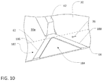
- FIG. 10 for example, still another example cleaning feature for the belt 30 is shown, configured as a chevron-shaped cleaning feature 182.
- the cleaning feature 182 may be configured similarly to one of the trapezoidal features 98 (see FIG. 6 ), but with an open region 184 between forward and rearward angled arms 186 and 188.
- the view of FIG. 10 does not include a trailing-edge region of the belt 30. It will be understood, however, that cleaning features similar to the cleaning feature 182 (or others) may be used as trailing-edge cleaning features for the belt 30.
- the cleaning feature 182 may be included in cleaning feature arrays (not shown in FIG.
- the opposite arms 186 and 188 of the cleaning feature 182 may intersect at inner ends of the arms 186 and 188, such that the cleaning feature 182 may exhibit a triangular chevron pattern, rather than a trapezoidal chevron pattern.
- cleaning features and cleaning feature arrays are presented above. It will be understood that various combinations of these and other features and arrays may be used for a given belt in order to provide a two-sided cleaning arrangement.
- similar patterns of features or types of arrays may be used at leading and trailing regions.
- different patterns of features or types of arrays may be used alternately (or in other combination) along a particular leading or trailing region of a belt.
- features similar to the trapezoidal features 98 may be combined with ridges and recesses such as in the arrays 120.
- different patterns of features or types of arrays may be used at a leading region than are used at a trailing region.
- features similar to the trapezoidal features 98 may be used along a trailing region and features similar to the ridges and recesses in the arrays 120 may be used along a leading region.
- the dimensions (or other geometry) of leading region cleaning features e.g., heights above the relevant crop-carrying surface
- leading region cleaning features may be configured differently than the dimensions (or other geometry) of trailing region cleaning features.
- the relevant belt e.g., the belt 30
- the relevant belt may be configured to be reversible, such that the belt may be installed on a header (e.g., the header 20) with either edge of the belt serving as the leading (or trailing) edge.
- a header e.g., the header 20
- reversal of the belt may allow for continued cleaning at the leading edge even after the originally leading edge features have become worn.
- variation between leading and trailing cleaning features may sometimes allow an operator to reverse a belt in order to customize cleaning functionality for a particular harvesting operation.
- a belt with more aggressive cleaning features at a first edge e.g., features with relatively large heights above the crop-carrying surface or relatively aggressively angled forward features
- less aggressive cleaning features at a second edge e.g., features with relatively small heights above the crop-carrying surface or less aggressively angled forward features
- first edge e.g., features with relatively large heights above the crop-carrying surface or relatively aggressively angled forward features
- less aggressive cleaning features at a second edge e.g., features with relatively small heights above the crop-carrying surface or less aggressively angled forward features
Landscapes
- Life Sciences & Earth Sciences (AREA)
- Environmental Sciences (AREA)
- Engineering & Computer Science (AREA)
- Mechanical Engineering (AREA)
- Belt Conveyors (AREA)
Abstract
Description
- This disclosure relates to draper headers, and more particularly to cleaning arrangements for belts of draper headers.
- Agricultural harvesters use a variety of implements attached to their front ends to gather crops. One type of these implements is called a "draper" or a "draper header". Conventional draper headers use conveyors with endless belts to carry cut crop material from leading-edge knives to center regions of the headers. From there, the cut crop material is conveyed into the harvesters. Once in the harvester, the cut crop material is further processed by separating grain from unwanted crop material (typically called "material other than grain" or "MOG").
- In some configurations, crop material can become lodged in various spaces on and around the belts, resulting in sub-optimal performance of the header. For example, some headers include crop ramps that extend rearwardly (from a frame of reference of the relevant vehicle) from the knives over the leading edge of the headers' endless belts. These crop ramps help to lift the cut crop material onto the endless belts for transport along the header. However, crop material can become lodged in gaps between the crop ramps and the endless belts, to the detriment of header performance. Crop material can also become lodged in, and pass through, other gaps along the belts. In some cases, this can require machine stoppage in order to clear crop material from the headers' internal areas.
- A two-sided cleaning arrangement is disclosed for endless belts, such as endless belts of draper headers.
- According to one aspect of the disclosure, an endless belt for a header with a crop ramp and a trailing cover may include a crop-carrying surface and first and second cleaning regions that are at least partly separated from each other by the crop-carrying surface. The cleaning regions may include respective cleaning features that extend above or are recessed below the crop-carrying surface, in order to clean crop material from below the crop ramp and the trailing cover, respectively.
- According to another aspect of the disclosure, an endless belt for a header with a crop ramp and a trailing cover may include a crop-carrying surface extending at least partly between the crop ramp and the trailing cover. The endless belt may also include first and second cleaning regions at least partly separated from each other by the crop-carrying surface. The cleaning regions may include respective arrays of cleaning features with respective pluralities of alternating ridges and recesses.
- According to yet another aspect of the disclosure, an endless belt may include first and second cleaning features disposed in first and second edge regions, respectively, of the endless belt. At least part of each cleaning surface may extend above or be recessed below a crop-carrying surface of the belt.
- The details of one or more implementations of the disclosure are set forth in the accompanying drawings and the description below. Other features and advantages will become apparent from the description, the drawings, and the claims.
-
FIG. 1 is a perspective view of an agricultural draper header with a crop ramp, trailing cover, and endless belt; -
FIG. 2A is an enlarged perspective view of a leading portion of the draper header ofFIG. 1 , including the crop ramp and a first cleaning feature of the endless belt; -
FIG. 2B is a schematic sectional view of the crop ramp and part of the endless belt, including the first cleaning feature; -
FIG. 3A is an enlarged perspective view of a trailing portion of the draper header ofFIG. 1 , including the trailing cover and a second cleaning feature of the endless belt; -
FIG. 3B is a schematic sectional view of the trailing cover and part of the endless belt ofFIG. 1 , including the second cleaning feature; -
FIG. 4 is a perspective view of a two-sided cleaning arrangement for the endless belt ofFIG. 1 ; -
FIG. 5A is a perspective view of another two-sided cleaning arrangement for the endless belt ofFIG. 1 ; -
FIG. 5B is a schematic sectional view of cleaning features of the cleaning arrangement ofFIG. 5A ; -
FIG. 6 is a perspective view of another two-sided cleaning arrangement for the endless belt ofFIG. 1 , with an array of cleaning features; -
FIG. 7 is a perspective view of another two-sided cleaning arrangement for the endless belt ofFIG. 1 , with another array of cleaning features; -
FIG. 8 is a perspective view of another two-sided cleaning arrangement for the endless belt ofFIG. 1 , with another array of cleaning features; -
FIG. 9 is a perspective view of another two-sided cleaning arrangement for the endless belt ofFIG. 1 , with another array of cleaning features; and -
FIG. 10 is a perspective view of a third cleaning feature for use in a two-sided cleaning arrangement. - Like reference numerals in the drawings indicate like components, parts, or operations.
- As used herein, with respect to an endless belt, unless otherwise defined or limited, the term "forward" (and the like) corresponds to a forward direction of travel of the belt, with respect to a supporting frame (e.g., a frame of a draper header), during normal operation of the belt. Likewise, the term "rearward" (and the like) corresponds to a direction opposite the forward direction of travel of the belt. In this regard, for example, a "forward facing" feature on an endless belt may generally face in the direction that the belt travels during normal operation, while a "rearward facing" feature may generally face opposite that direction.
- Also as used herein, with respect to a header (or components thereof), unless otherwise defined or limited, the term "leading" (and the like) indicates a direction of travel of the header during normal operation (e.g., the forward direction of travel of a harvester vehicle carrying the header). Similarly, the term "trailing" (and the like) indicates a direction that is opposite the leading direction. In this regard, for example, a "leading" edge of a knife assembly of a draper header may be generally disposed at the front of the knife assembly, with respect to the direction travel of the draper header during normal operation (e.g., as carried by a harvester vehicle). Likewise, a "trailing" edge of the knife assembly may be generally disposed at the back of the knife assembly, with respect to the direction of travel of the draper header during normal operation.
- It will be understood that "leading" and "trailing" may not necessarily denote the extreme leading or trailing edge of a body. For example, a trailing cover on an agricultural header may trail behind certain features, such as a leading-edge knife or endless belt, but may not necessarily be at the trailing end of the entire header. Further, in some embodiments discussed herein, an endless belt may be configured to be reversed on a conveyor, such that a particular edge of the belt may be either a leading edge or a trailing edge, depending on the orientation of the belt. Accordingly, unless otherwise defined or limited, the terms "leading" and "trailing" may be used herein with respect to reversible endless belts (or features thereupon) to indicate a currently-addressed orientation of the belt (or feature), rather than an absolute orientation.
- As noted above, operation of an endless belt for crop transport may result in crop material becoming lodged in or passing through various clearances, to the detriment of overall header performance. For example, during operation of an endless belt for a draper header, cut crop material may be pushed into, and generally lodged within, a clearance between crop ramps of the header and a leading portion of the endless belt. Similarly, crop material may be pushed into, and sometimes pass through, a clearance between a trailing cover (e.g., a back sheet deflector or rear frame cover) and a trailing portion of the endless belt. Each of these results may adversely affect performance of the endless belt and of the header as a whole. Among other benefits, the disclosed two-sided cleaning arrangement may address these issues.
- Generally, a two-sided cleaning arrangement for an endless belt includes cleaning features on leading and trailing portions of an endless belt. In a belt for a draper header, for example, a leading portion of the belt near a crop ramp (or similar feature) may include a first set of cleaning features, and a trailing portion of the belt near a trailing cover (or similar feature) may include a second set of cleaning features. During operation, such a two-sided configuration may help to remove crop material from a gap between the belt and the crop ramp and from a gap between the belt and the trailing cover. Further, in some configurations, as cleaning features on the leading (or trailing) portion of a belt suffer from wear or other degradation, the orientation of the belt on the header may be reversed such that the previously trailing (or leading) portion of the belt is oriented as a leading (or trailing) portion of the belt for subsequent operation. Accordingly, the cleaning features on the previously trailing (or leading) portion of the belt may continue to provide cleaning functionality at a leading (or trailing) region, even after relatively significant wear to cleaning features at the other edge of the belt, and the useful life of the belt may be extended.
- Cleaning features according to the present disclosure may exhibit (e.g., be formed in the shape of) a variety of patterns. In some embodiments, cleaning features may be formed as polygonal or other shapes that are raised away from, or recessed below, a cleaning surface of a belt. For example, cleaning features may be formed as rectangles, triangles, chevrons, and so on, which either extend above a cleaning surface of a belt, or are recessed below (i.e., extend below) the cleaning surface. In some embodiments, a cleaning feature may extend forward (i.e., along the direction of motion of the belt during normal operation) from a trailing end of the feature to a leading end of the feature (or vice versa). In some embodiments, varying geometries may be used, such that a cleaning feature may include portions configured as rectangles, portions configured as triangles, raised portions, recessed portions, and so on.
- In some embodiments, cleaning features on a leading or trailing edge of belt may be arranged within a cleaning region that extends over a substantial portion of the circumferential length of the belt. In some embodiments, cleaning features may be arranged in various arrays within the cleaning region. For example, a cleaning feature such as a raised rectangle or triangle may be repeated (with or without geometric variation of the rectangle or triangle) in an array that extends along 25% or more (e.g., 50%) of a belt. In this way, cleaning functionality may be provided by the array of cleaning features at multiple points along the belt.
- In some embodiments, an array of cleaning features may include different types of cleaning features, such as rectangular ridges and raised triangles. In some embodiments, an array of cleaning features may include alternating raised and recessed geometries. For example, in some cleaning feature arrays, raised cleaning features (i.e., cleaning features extending above a cleaning surface of a belt) such as raised rectangles or triangles may alternate with recessed cleaning features (i.e., cleaning features extending below the cleaning surface) along a belt. In some embodiments, such an array of cleaning features may be continuous along the entire circumferential length of the belt.
- In some embodiments, one array of cleaning features at a leading or trailing edge of a belt may be separated from another array of cleaning features on the relevant edge by various distances. In some embodiments, cleaning feature arrays (or individual cleaning features) may be separated from each other by portions of a belt without cleaning features. For example, an array of alternating ridges and recesses on a cleaning belt may be separated from another array on the belt by one or more flattened regions on the belt. Such flattened regions may be flush with a crop-carrying surface of the belt, or may extend above or be recessed below the crop-carrying surface. This may allow for variations in cleaning effects along a circumferential length of a belt, and may also facilitate various manufacturing processes.
- In some embodiments, a cleaning feature may be aligned with other features on a belt. For example, a cleaning feature at a leading or trailing edge of a belt may be generally aligned with a cleat extending over a central portion of the belt. In some embodiments, cleaning features at a leading edge of a belt may vary in pattern or in disposition (e.g., orientation or order) within an array from cleaning features at a trailing edge of the belt.
- Various examples and discussion herein address endless belts for use with draper headers. It will be understood that this configuration is presented as an example only and that various other applications may be possible.
- Referring now to
FIG. 1 , anexample draper header 20 is depicted. In various embodiments, the disclosed cleaning arrangements may be used with theheader 20, or with other headers, including other draper headers. As depicted, theheader 20 includes aframe 22 that supports left- and right-side conveyors center conveyor 28. ("Left" and "right," with respect to the header, are taken from the perspective of an operator of a trailing agricultural harvester (not shown) carrying the header.) Each of theconveyors endless belts header 20. As depicted, twobelts 30 and twobelts 32 are included on each side of theheader 20. In other embodiments, other numbers of belts may be used. In some embodiments thebelts belts belts header 20 inrespective directions belts center conveyor 28, which may in turn use thebelt 34 move the material off of theheader 20 and into an associated harvester vehicle (not shown). As depicted, for example, acylindrical conveyor 40 may be configured receive cut crop material from thecenter conveyor 28 and carry the crop material rearward (i.e., in a direction 44) through an aperture in theframe 22 and into the harvester (not shown). - In the embodiment depicted,
various cleats 42 are fixed to the surface of each of theendless belts cleats 42 generally extending in a direction transverse to the direction of travel of therespective belt cleat 42 may extend only partly across the respective width of thebelts belts cleats 42 exhibit a generally trapezoidal cross-section, with curved lower vertices (seeFIG. 2A ). In other embodiments, other configurations of thecleats 42 may be possible. - To cut crop material from a field, the
header 20 ofFIG. 1 includes a reciprocatingknife 50 that extends across substantially the entire length of theheader 20. In various embodiments, theheader 20 may also include a leading cover arranged between the reciprocatingknife 50 and thevarious belts belts FIG. 1 , for example, theheader 20 includes an elongate row of interlocking crop ramp segments 52 (see alsoFIG. 2A ), that extend along substantially the entire length of theheader 20. - As depicted, the
header 20 also includes a trailing cover 46 (e.g., a back sheet deflector or rear frame cover) separated from thecrop ramp segments 52 by awidth 48. The trailingcover 46 may serve to cover and protect various internal components of theheader 20, and may also generally define a trailing end of a crop-carrying region of theheader 20. In some embodiments, thecleats 42 may extend over theentire width 48. In other embodiments, thecleats 42 may extend over only a fraction of thewidth 48. - During a harvesting operation, the harvester vehicle (not shown) may carry the
header 20 through an agricultural field in a nominalforward direction 54. As theheader 20 is moved across the field, the reciprocatingknife 50 may operate at the leading edge of theheader 20 to sever the crops adjacent to the ground, and the cut crop material may fall in a trailing direction (i.e., generally opposite the direction 54), onto one or more of the threeconveyors left side conveyor 24 may then carry the crop material rightward, using the twobelts 30, toward the center of theheader 20. Theright side conveyor 26 may carry the crop material leftward, using the twobelts 32, toward the center of theheader 20, and thecenter conveyor 28 may carry the crop material rearward toward and underneath thecylindrical conveyor 40. (As noted above, these crop movements may each be viewed as a "forward" movement, from the perspective of therespective belts conveyor 40 is then moved in the trailing direction through the aperture in theframe 22 of theheader 20 and thence into the agricultural harvester (not shown). - As depicted, the left-
side conveyor 24 and the right-side conveyor 26 are similarly configured, although theconveyors conveyors side conveyor 24 may be applicable to the right-side conveyor 26, as well as other conveyors of other embodiments. - During a harvesting operation using the header 20 (or other headers), crop material carried by the various belts (e.g., the
belts 30 and 32) may tend to become lodged in recesses or pinch-points near the path of the belts. For example, as depicted inFIG. 2A for the left-side conveyor 24, theheader 20 may include thecrop ramp segments 52a through 52c, each generally disposed adjacent to and overlapping with neighboring instances of thesegments 52. Each of thecrop ramp segments 52 generally extends in the trailing direction from a corresponding leading edge 60 (e.g., leadingedges 60a through 60c) to a corresponding trailing edge 62 (e..g, trailingedges 62a through 62c). Generally, the trailingedges 62 of thecrop ramp segments 52 at least partly cover a leading edge of the relevant belt. As depicted, for example, the trailingedges 62a through 62c of thecrop ramp segments 52a through 52c cover aleading edge 64 of thebelt 30. As such, as depicted for the trailingedge 62b inFIG. 2B , each of the trailingedges 62 may generally define agap 66 with aclearance 66a between the crop-carryingsurface 30a of the belt 30 (or other crop-carrying surfaces of other belts) and thecorresponding ramp segment 52. - Some embodiments of the
crop ramp segments 52 may include features disposed within thegap 66. For example, in the embodiment depicted inFIG. 2A , elongate recesses 68 are formed on the underside of each of thecrop ramp segments 52a through 52c. As depicted, the recesses 68 extend at an angle with respect to thebelt 30, such that the recesses 68 extend forward, with respect to thedirection 36 of belt travel, and in the trailing direction, with respect to thedirection 54 of header travel, from the leading ends of the recesses 68 to the trailing ends of the recesses 68. In other embodiments, other configurations may be used, or other (or no) features may be included on thecrop ramp segments 52 within thegap 66. Generally, the recesses 68 may assist in removing cut crop material from thegap 66, in a manner that is complimentary to the belt cleaning arrangements disclosed herein. - In the embodiment depicted in
FIG. 2A , a leading-edge cleaning feature 70 is included on thebelt 30 near thecrop ramp segments 52. As depicted, thecleaning feature 70 is configured as a generally rectangular body extending (i.e., raised) above the crop-carryingsurface 30a. In other embodiments, other geometries may be used. In some embodiments, thefeature 70 may be integrally formed with thebelt 30. In some embodiments, thefeature 70 may be separately formed then securely bonded or otherwise attached to thebelt 30. - As depicted, the
feature 70 exhibits amaximum height 72 above the crop-carryingsurface 30a that is somewhat less than thetotal clearance 66a between theramp segment 52b and the crop-carryingsurface 30a. Accordingly, as thebelt 30 travels along thedirection 36, thefeature 70 may sweep crop material out of thegap 66 without substantially interfering with theramp segment 52b. In some embodiments, the feature 70 (or another cleaning feature) may exhibit a maximum height that is substantially equal to theclearance 66a, such that thefeature 70 directly contacts the underside of theramp segment 52b. In some embodiments, the feature 70 (or another cleaning feature) may exhibit a maximum height that is larger than theclearance 66a, such that thefeature 70 may bear on theramp segment 52b and urge theramp segment 52b upward during operation. - As depicted, the
feature 70 includes a forward facingsurface 70a that is generally perpendicular to the crop-carryingsurface 30a, and that tends to engage cut crop material embedded within thegap 66 and carry that material along thedirection 36. Thefeature 70 also includes a rearward facingsurface 70b that is generally perpendicular to the crop-carryingsurface 30a and generally parallel to theforward facing surface 70a. Thefeature 70 also includes a generally planartop surface 70c, which is generally parallel to the crop-carryingsurface 30a of thebelt 30 and has a generally constant width, as measured along thedirection 36. In other embodiments, other configurations may be possible. - Also as depicted, the
feature 70 generally extends from the leadingedge 64 of thebelt 30 to a leading end of theadjacent cleat 42, with which thefeature 70 is aligned. Where, as inFIG. 2A , thecleat 42 does not extend over the entire width 48 (seeFIG. 1 ), such a configuration of thefeature 70 results in a portion of thefeature 70 extending outside of thegap 66 onto the central region of the crop-carryingsurface 30a of thebelt 30. In some embodiments, thefeature 70 may not extend outside of thegap 66, such that theentire feature 70 may be covered by one (or more) of thecrop ramp segments 52. In some embodiments, thefeature 70 may not extend into thegap 66, such that theentire feature 70 may be disposed outside of thegap 66. In some embodiments, the feature 70 (or other leading-edge cleaning features) may not be aligned with thecleat 42. - In a two-sided cleaning arrangement, another cleaning feature may be included at the trailing edge of the relevant belt, such as where a trailing cover generally covers at least part of belt. Referring also to
FIGS. 3A and 3B , for example, the trailingcover 46 generally covers at least part of a trailingedge 80 of thebelt 30. As such, a leadingedge 82 of thecover 46 may generally define agap 84 with aclearance 84a between the crop-carryingsurface 30a of the belt 30 (or other crop-carrying surfaces of other belts) and thecover 46. - To provide a two-sided cleaning arrangement, a trailing-
edge cleaning feature 86 is included on thebelt 30 near thecrop ramp segments 52. As depicted, thecleaning feature 86 is configured as a generally rectangular body extending (i.e., raised) above the crop-carryingsurface 30a. In other embodiments, other geometries may be used. In some embodiments, thefeature 86 may be integrally formed with thebelt 30. In some embodiments, thefeature 86 may be separately formed then securely bonded or otherwise attached to thebelt 30. - As depicted, the
feature 86 exhibits amaximum height 88 above the crop-carryingsurface 30a that is somewhat less than thetotal clearance 84a between theleading edge 82 of the trailingcover 46 and the crop-carryingsurface 30a. Accordingly, as thebelt 30 travels along thedirection 36, thefeature 86 may sweep crop material out of thegap 84 without substantially interfering with the trailingcover 46. In some embodiments, the feature 86 (or another cleaning feature) may exhibit a maximum height that is substantially equal to theclearance 84a, such that thefeature 86 directly contacts the underside of the trailingcover 46. In some embodiments, the feature 86 (or another cleaning feature) may exhibit a maximum height that is larger than theclearance 84a, such that thefeature 86 may bear on the trailingcover 46 and urge the trailingcover 46 upward during operation. - As depicted, the
feature 86 includes a forward facing surface 86a that is generally perpendicular to the crop-carryingsurface 30a, and that tends to engage cut crop material embedded within thegap 66 and carry that material along thedirection 36. Thefeature 86 also includes a rearward facing surface 86b that is generally perpendicular to the crop-carryingsurface 30a and generally parallel to the forward facing surface 86a. Thefeature 86 also includes a generally planar top surface 86c, which is generally parallel to the crop-carryingsurface 30a of thebelt 30 and has a generally constant width, as measured along thedirection 36. In other embodiments, other configurations may be possible. - Also as depicted, the
feature 86 generally extends from the trailingedge 80 of thebelt 30 to a trailing end of theadjacent cleat 42, with which thefeature 86 is aligned. Where, as inFIG. 3A , thecleat 42 does not extend over the entire width 48 (seeFIG. 1 ), such a configuration of thefeature 86 results in a portion of thefeature 86 extending outside of thegap 84 onto the central region of the crop-carryingsurface 30a of thebelt 30. In some embodiments, thefeature 86 may not extend outside of thegap 84, such that theentire feature 86 may be covered by the trailingcover 46. In some embodiments, thefeature 86 may not extend into thegap 84, such that theentire feature 86 may be disposed outside of thegap 84. In some embodiments, the feature 86 (or other trailing-edge cleaning features) may not be aligned with thecleat 42. - As depicted, the cleaning features 70 and 86 are configured with similar geometry, each exhibiting a generally uniform rectangular cross-section, generally uniform height, width (i.e., as measured along the forward/rearward directions of the belt 30), and length (i.e., as measured along the leading/trailing directions). In some embodiments, trailing-edge cleaning features for a belt may vary from leading-edge cleaning features, including with regard to overall shape, particular dimensions, distribution and orientation on the relevant belt, and so on.
- Referring also to
FIG. 4 , another example two-sided cleaning arrangement is depicted for thebelt 30, with leading- and trailing-edge cleaning features 96 and 98, respectively. Generally, the cleaning features 96 and 98 may be formed in different patterns than the cleaning features 70 and 86 depicted inFIGS. 2A through 3B . As depicted, for example, each of thefeatures surface surface surface 30a but angle away from thetravel direction 36 for thebelt 30. As depicted, thesurfaces cleaning feature 98 widens, with respect to thedirection 36, from the leading to the trailing end of thefeature 98. Likewise, thesurfaces cleaning feature 96 narrows, with respect to thedirection 36, from the leading to the trailing end of thefeature 96. This may result in improved engagement of crop material lodged within thegaps 66 and 84 (seeFIGS. 2A through 3B ) and improved conveyance of the crop material from out of thegaps surfaces 100 through 106 angling in an opposite direction from that depicted inFIG. 4 . In some embodiments, theopposite surfaces cleaning feature 96 and theopposite surfaces cleaning feature 98 may meet at inner ends of thesurfaces 100 through 106, such that the cleaning features 96 and 98 may exhibit triangular, rather than trapezoidal, patterns. - For clarity in
FIG. 4 , thecrop ramp segments 52 and trailingcover 46 are not shown. However, the leadingedge 82 of the trailingcover 46 and the trailingedge 62 of thecrop ramp segments 52 are depicted as dotted lines. Accordingly, it can be seen that a trailing portion of thecleaning feature 96 extends in the trailing direction past the trailingedge 62 of thecrop ramp segments 52. Similarly, it can be seen that a leading portion of thecleaning feature 98 extends in the leading direction past the leadingedge 82 of the trailingcover 46. Also as depicted inFIG. 4 , the cleaning features 96 and 98 extend from the leading and trailingedges belt 30, respectively, to leading and trailing ends of thecleat 42, respectively. In other embodiments, other configurations may be possible, including configurations in which one or both of the cleaning features 96 and 98 are entirely covered by thecrop ramp segments 52 or trailingcover 46, and configurations in which one or both of the cleaning features 96 and 98 do not extend into thegaps - Referring also to
FIG. 5A , another example two-sided cleaning arrangement is depicted for thebelt 30, with leading- and trailing-edgecleaning feature arrays cleaning feature arrays FIG. 5B , for example, thecleaning feature array 120 includes threeridges maximum height 130 above the crop-carryingsurface 30a and separated byrecesses ridges common width 136 and generally planar top surfaces that are generally parallel with the crop-carryingsurface 30a. Similarly, therecesses common width 138, which may be the same as thewidth 136, and generally planar bottom surfaces that are generally parallel with the crop-carryingsurface 30a. In other configurations, other spacings and geometries may be used, as may different numbers of ridges or recesses. In some embodiments, therecesses surface 30a, as shown at therecess extensions various ridges various recesses - For clarity in
FIG. 5A , thecrop ramp segments 52 and trailingcover 46 are not shown. However, the leadingedge 82 of the trailingcover 46 and the trailingedge 62 of thecrop ramp segments 52 are depicted as dotted lines. Accordingly, it can be seen that a trailing portion of thecleaning feature array 120 extends in the trailing direction past the trailingedge 62 of thecrop ramp segments 52. Similarly, it can be seen that a leading portion of thecleaning feature array 122 extends in the leading direction past the leadingedge 82 of the trailingcover 46. Also as depicted inFIG. 5A , thecleaning feature arrays edges belt 30, respectively, to leading and trailing ends of thecleat 42, respectively. In other embodiments, other configurations may be possible, including configurations in which one or both of thecleaning feature arrays crop ramp segments 52 or trailingcover 46, and configurations in which one or both of thecleaning feature arrays gaps 66 or 84 (seeFIGS. 2A through 3B ). - In some embodiments, arrays of cleaning features may extend over a substantial portion (e.g., 25% or more) of the circumferential length of the relevant belt. Referring also to
FIG. 6 , for example, instances of thefeatures 96 and 98 (seeFIG. 4 ) can be arranged in repeating arrays along thebelt 30. For example, a leading-edge array 150 with cleaningfeatures 96a though 96e (and others (not shown)) may extend along a leading region of thebelt 30, including over 25% or more of the circumferential length of thebelt 30. As depicted, relativelyuniform gaps 152a through 152d are provided along thebelt 30 between thevarious features 96a through 96e. In other embodiments, different sized gaps, non-uniform gaps, or no gaps, may be provided between thevarious features 96a through 96e. - Similarly, a trailing-
edge array 154 with cleaningfeatures 98a though 98e (and others (not shown)) may extend along a trailing region of thebelt 30, including over 25% or more of the circumferential length of thebelt 30. As depicted, relativelyuniform gaps 156a through 156d are provided along thebelt 30 between thevarious features 98a through 98e. In other embodiments, different sized gaps, non-uniform gaps, or no gaps, may be provided between thevarious features 98a through 98e. - As depicted in
FIG. 6 , the leading-edge array 150 and the trailing-edge array 154 are generally similar. Further, the narrower inner "peaks" of the various trapezoidal features 96 and 98 are generally aligned across thebelt 30, as can be particularly seen for thefeatures cleat 42. In some embodiments, the leading-edge array 150 and the trailing-edge array 154 may be configured differently from each other. Likewise, in some embodiments, thevarious features 96 may be offset from corresponding features 98 (e.g., with inner "peaks" of thefeatures 96 generally aligned with the various gaps 156). - In some embodiments, a two-sided cleaning arrangement may include cleaning features configured as ridges and recesses arranged in arrays on opposite edges of the relevant belt. Referring also to
FIG. 7 , sets of ridges and recesses similar to thearrays 120 and 122 (seeFIG. 5A ) may be arranged in repeating arrays along leading and trailingedges belt 30. In the embodiment depicted, a leading-edge array 160 extends along a leading region of the belt 30 (e.g., extending over 25% or more of the belt length), with various sets of ridges and recesses forming sub-arrays of the larger array 160 (e.g., as represented by the sub-arrays 120a through 120d). Likewise, a trailing-edge array 162 extends along a trailing region of the belt 30 (e.g., extending over 25% or more of the belt length), with various sets of ridges and recesses forming sub-arrays of the larger array 162 (e.g., as represented by the sub-arrays 122a through 122d). As depicted, relativelyuniform gaps 164a through 164c and 166a through 166c are provided along thebelt 30 between the various sub-arrays 120a through 120d and 122a through 122d, respectively. In other embodiments, different sized gaps, non-uniform gaps, or no gaps, may be provided between the various sub-arrays 120a through 120d and 122a through 122d (or between the ridges or other features of the sub-arrays 120a through 120d and 122a through 122d). - As depicted in
FIG. 7 , the leading-edge array 160 and the trailing-edge array 162 are generally similar. Further, the various sub-arrays 120a through 120d are generally aligned across thebelt 30 with the various sub-arrays 122a through 122d, as can be particularly seen for the sub-arrays 120d and 122d that are adjacent to thecleat 42. In some embodiments, the leading-edge array 160 and the trailing-edge array 162 may be configured differently from each other. Likewise, in some embodiments, the various sub-arrays 120a through 120d may be offset from corresponding sub-arrays 122a through 122d (e.g., with the sub-array 120a generally aligned with one of the various gaps 166). - In some embodiments, one or more flattened regions may separate various sub-arrays of an array of cleaning features on a belt. For example, referring to
FIG. 8 , flattenedregions edge array 174 and trailing-edge array 176, respectively, may be formed from separating sets (i.e., sub-arrays) of ridges and recesses along thebelt 30. As depicted, the flattenedregions regions regions direction 36 may be generally larger than thewidth 136 or the width 138 (seeFIG. 5B ) of the ridges or recesses of the various sub-arrays (e.g., the sub-arrays 120a and 122a). Likewise, in some embodiments, the width of theregions surface 30a, be recessed below the crop-carryingsurface 30a, or be flush with the crop-carryingsurface 30a. - In other embodiments, other configurations may be possible. Referring to
FIG. 9 , for example, various ridges and recesses similar to the ridges and recesses of cleaningfeature arrays feature arrays direction 36 other than from the recesses of thearrays 178 and 180 (e.g., recesses similar to therecesses FIG. 5B ). - As also noted above, in some embodiments, cleaning features for the belt may exhibit still other patterns. Referring to
FIG. 10 , for example, still another example cleaning feature for thebelt 30 is shown, configured as a chevron-shapedcleaning feature 182. Generally, thecleaning feature 182 may be configured similarly to one of the trapezoidal features 98 (seeFIG. 6 ), but with anopen region 184 between forward and rearward angledarms FIG. 10 does not include a trailing-edge region of thebelt 30. It will be understood, however, that cleaning features similar to the cleaning feature 182 (or others) may be used as trailing-edge cleaning features for thebelt 30. Likewise, it will be understood that thecleaning feature 182 may be included in cleaning feature arrays (not shown inFIG. 10 ), such as in repeating arrays of multiple cleaning features that are patterned similarly to thecleaning feature 182. In some embodiments, theopposite arms cleaning feature 182 may intersect at inner ends of thearms cleaning feature 182 may exhibit a triangular chevron pattern, rather than a trapezoidal chevron pattern. - Various examples of cleaning features and cleaning feature arrays are presented above. It will be understood that various combinations of these and other features and arrays may be used for a given belt in order to provide a two-sided cleaning arrangement. In some embodiments, similar patterns of features or types of arrays may be used at leading and trailing regions. In some embodiments, different patterns of features or types of arrays may be used alternately (or in other combination) along a particular leading or trailing region of a belt. For example, in some features or arrays, features similar to the trapezoidal features 98 may be combined with ridges and recesses such as in the
arrays 120. In some embodiments, different patterns of features or types of arrays may be used at a leading region than are used at a trailing region. For example, features similar to the trapezoidal features 98 may be used along a trailing region and features similar to the ridges and recesses in thearrays 120 may be used along a leading region. Likewise, the dimensions (or other geometry) of leading region cleaning features (e.g., heights above the relevant crop-carrying surface) may be configured differently than the dimensions (or other geometry) of trailing region cleaning features. - In some embodiments, the relevant belt (e.g., the belt 30) may be configured to be reversible, such that the belt may be installed on a header (e.g., the header 20) with either edge of the belt serving as the leading (or trailing) edge. Where, for example, the leading edge features suffers from greater wear than the trailing edge features, reversal of the belt may allow for continued cleaning at the leading edge even after the originally leading edge features have become worn. As another potential benefit, variation between leading and trailing cleaning features may sometimes allow an operator to reverse a belt in order to customize cleaning functionality for a particular harvesting operation. For example, a belt with more aggressive cleaning features at a first edge (e.g., features with relatively large heights above the crop-carrying surface or relatively aggressively angled forward features) and less aggressive cleaning features at a second edge (e.g., features with relatively small heights above the crop-carrying surface or less aggressively angled forward features) can be arranged on a conveyor with the first edge of the belt as the leading edge or as the trailing edge, depending on whether more or less aggressive cleaning is desired at the leading edge.
- The terminology used herein is for the purpose of describing particular embodiments only and is not intended to be limiting of the disclosure. As used herein, the singular forms "a", "an" and "the" are intended to include the plural forms as well, unless the context clearly indicates otherwise. It will be further understood that any use of terms "comprises" and/or "comprising" in this specification specifies the presence of stated features, integers, steps, operations, elements, and/or components, but do not preclude the presence or addition of one or more other features, integers, steps, operations, elements, components, and/or groups thereof.
Claims (15)
- An endless belt (30) for use with an agricultural draper header (20) with a crop ramp (52) that is separated from a trailing cover (46) by a first width, the endless belt comprising:a crop-carrying surface (30a) extending at least partly over the first width;a first cleaning region; anda second cleaning region at least partly separated from the first cleaning region by the crop-carrying surface;wherein the first cleaning region at least partly includes a first cleaning feature (70, 96), at least part of the first cleaning feature one or more of extending above and being recessed below the crop-carrying surface to clean crop material from the below the crop ramp; and
wherein the second cleaning region at least partly includes a second cleaning feature (86, 98), at least part of the second cleaning feature one or more of extending above and being recessed below the crop-carrying surface to clean crop material from below the trailing cover. - The endless belt of claim 1, wherein at least one of the first and second cleaning features includes ridges (124, 126, 128) extending above the crop-carrying surface and recesses (132, 134) interspersed with the ridges.
- The endless belt of claim 1, wherein one or more of a first array (150, 160, 174, 178) of cleaning features and a second array (154, 162, 176, 180) of cleaning features extends over at least 25% of a circumferential length of the endless belt, the first and second cleaning feature arrays including, respectively, the first and second cleaning features.
- The endless belt of claim 3, wherein the one or more of the first and second cleaning features includes ridges (124, 126, 128) extending above the crop-carrying surface and recesses (132, 134) interspersed with the ridges.
- The endless belt of claim 1, wherein a maximum extension (72) of the first cleaning feature above the crop-carrying surface is smaller than a minimum clearance (66a) between a trailing edge (62b) of the crop ramp and the crop-carrying surface.
- The endless belt of claim 5, wherein the maximum extension (88) of the second cleaning feature above the crop-carrying surface is smaller than a minimum clearance (84a) between a leading edge (82) of the trailing cover and the crop-carrying surface.
- The endless belt of claim 1, wherein a respective maximum extension of each of the first and second cleaning features (72, 88) is smaller than a minimum clearance (66a) between a trailing edge (63b) of the crop ramp and the crop-carrying surface and smaller than a minimum clearance (84a) between a leading edge (82) of the trailing cover and the crop-carrying surface.
- The endless belt of claim 1, wherein the first cleaning feature exhibits a first pattern (86) and the second cleaning feature exhibits a second pattern (98, 182) different from the first pattern.
- An endless belt (30) for use with an agricultural draper header (20) with a crop ramp (52) that is separated from a trailing cover (46) by a first width, the endless belt comprising:a crop-carrying surface (30a) extending at least partly over the first width;a first cleaning region; anda second cleaning region at least partly separated from the first cleaning region by the crop-carrying surface;wherein the first cleaning region at least partly includes a first array (160, 174, 178) of first cleaning features, the first array including a first plurality of alternating ridges and recesses (124, 126, 128, 132, 134); and
wherein the second cleaning region at least partly includes a second array (162, 176, 180) of second cleaning features, the second array including a second plurality of alternating ridges and recesses (124, 126, 128, 132, 134). - The endless belt of claim 9, wherein the first and second arrays include respective first and second pluralities of sub-arrays (120a-d, 122a-d), the first and second sub-arrays including respective first and second pluralities of alternating ridges and recesses having one or more respective first and second ridge and recess widths;
wherein at least first and second sub-arrays of the first plurality of sub-arrays are separated from each other by a first flattened region (170) of the first cleaning region, the first flattened region extending over a first width that is larger than at least one of the one or more first ridge widths and the one or more first recess widths; and
wherein at least third and fourth sub-arrays of the second plurality of sub-arrays are separated from each other by a second flattened region (172) of the second cleaning region, the second flattened region extending over a second width that is larger than at least one of the one or more second ridge widths and the one or more second recess widths. - An endless belt (30) for conveying crop material on an agricultural draper header (20), the endless belt comprising:a crop-carrying surface (30a);a first cleaning feature (70, 96) disposed in a first edge region of the endless belt, at least part of the first cleaning feature one or more of extending above and being recessed below the crop-carrying surface; anda second cleaning feature (86, 98) disposed in a second edge region of the endless belt that is at least partly separated from the first edge region of the endless belt by the crop-carrying surface, at least part of the second cleaning feature one or more of extending above and being recessed below the crop-carrying surface.
- The endless belt of claim 11, wherein at least one of the first and second cleaning features includes ridges (124, 126, 128) extending above the crop-carrying surface and recesses (132, 134) interspersed with the ridges, wherein preferably one or more of the recesses extend below the crop-carrying surface.
- The endless belt of claim 12, wherein the one or more of the first and second cleaning feature arrays includes ridges (124, 126, 128) extending above the crop-carrying surface and recesses (132, 134) interspersed with the ridges.
- The endless belt of claim 11, wherein a maximum extension (72) of the first cleaning feature above the crop-carrying surface is smaller than a maximum extension (88) of the second cleaning feature above the crop-carrying surface and/or wherein a maximum extension (72) of the first cleaning feature above the crop-carrying surface is larger than a maximum extension (88) of the second cleaning feature above the crop-carrying surface and/or wherein the first cleaning feature exhibits a first pattern (70) and the second cleaning feature exhibits a second pattern (98, 182) different from the first pattern.
- A draper header (20) with an endless belt (30) according to one of the preceding claims.
Applications Claiming Priority (1)
| Application Number | Priority Date | Filing Date | Title |
|---|---|---|---|
| US14/724,474 US9795086B2 (en) | 2015-05-28 | 2015-05-28 | Two-sided cleaning arrangements for endless belts |
Publications (2)
| Publication Number | Publication Date |
|---|---|
| EP3097761A1 true EP3097761A1 (en) | 2016-11-30 |
| EP3097761B1 EP3097761B1 (en) | 2019-10-23 |
Family
ID=56008531
Family Applications (1)
| Application Number | Title | Priority Date | Filing Date |
|---|---|---|---|
| EP16169885.7A Active EP3097761B1 (en) | 2015-05-28 | 2016-05-17 | Two sided cleaning arrangements for endless belt |
Country Status (4)
| Country | Link |
|---|---|
| US (1) | US9795086B2 (en) |
| EP (1) | EP3097761B1 (en) |
| BR (1) | BR102016011909A2 (en) |
| CA (1) | CA2930147C (en) |
Cited By (1)
| Publication number | Priority date | Publication date | Assignee | Title |
|---|---|---|---|---|
| US20220279722A1 (en) * | 2018-07-31 | 2022-09-08 | Cnh Industrial America Llc | Infeed belt conveyor at combine feeder |
Families Citing this family (5)
| Publication number | Priority date | Publication date | Assignee | Title |
|---|---|---|---|---|
| CA3149508A1 (en) * | 2017-02-24 | 2018-03-08 | IP Machinery Pty Ltd | Feeder device |
| BR112020023126B1 (en) * | 2018-05-17 | 2022-08-16 | Wcco Belting, Inc | BELT WITH LONGITUDINAL TEETH |
| US11297770B2 (en) * | 2019-11-13 | 2022-04-12 | Cnh Industrial America Llc | Draper belt assembly for an agricultural harvester |
| US11617305B2 (en) * | 2020-05-21 | 2023-04-04 | Cnh Industrial America Llc | Crop ramps for combine headers |
| US20230403978A1 (en) * | 2022-06-15 | 2023-12-21 | Cnh Industrial America Llc | Agricultural header with a draper belt including a seed saver disposed behind one or more crop ramps |
Citations (3)
| Publication number | Priority date | Publication date | Assignee | Title |
|---|---|---|---|---|
| US5456067A (en) * | 1994-04-04 | 1995-10-10 | Legg Company, Inc. | Oil resistant pick-up belt and swather canvas |
| US20150007544A1 (en) * | 2013-07-02 | 2015-01-08 | Deere & Company | Self clearing crop ramp |
| EP2896283A2 (en) * | 2014-01-15 | 2015-07-22 | Deere & Company | Draper header with belt cleaning arrangement |
Family Cites Families (9)
| Publication number | Priority date | Publication date | Assignee | Title |
|---|---|---|---|---|
| US3592556A (en) * | 1966-11-21 | 1971-07-13 | David R Campbell | Conveyor with nub belt |
| US4674627A (en) * | 1984-11-08 | 1987-06-23 | Proctor & Schwartz, Inc. | Sanitary conveyor assembly |
| US5350020A (en) | 1992-06-29 | 1994-09-27 | Vandever Billie C | Multi-crop harvester/windrower implement |
| US7549280B2 (en) * | 2006-03-02 | 2009-06-23 | Deere & Company | Sectionalized belt guide for draper belt in an agricultural harvesting machine |
| US8186136B2 (en) | 2009-04-03 | 2012-05-29 | Deere & Company | Agricultural harvester with a draper platform direction shuttle |
| US20110094201A1 (en) * | 2009-10-27 | 2011-04-28 | Duane Bomleny | Center Draper Belt With Crop Conveying Features |
| US8205421B2 (en) * | 2010-06-16 | 2012-06-26 | Agco Corporation | Belt guard crop dam for flexible draper header |
| US8322520B2 (en) * | 2010-08-17 | 2012-12-04 | Deere & Company | Tongue-in-groove belt hold down for a draper platform |
| DE102011014770A1 (en) * | 2011-03-23 | 2012-09-27 | Claas Saulgau Gmbh | Sealing system for a mower conveyor belt |
-
2015
- 2015-05-28 US US14/724,474 patent/US9795086B2/en active Active
-
2016
- 2016-05-16 CA CA2930147A patent/CA2930147C/en active Active
- 2016-05-17 EP EP16169885.7A patent/EP3097761B1/en active Active
- 2016-05-25 BR BR102016011909A patent/BR102016011909A2/en not_active Application Discontinuation
Patent Citations (3)
| Publication number | Priority date | Publication date | Assignee | Title |
|---|---|---|---|---|
| US5456067A (en) * | 1994-04-04 | 1995-10-10 | Legg Company, Inc. | Oil resistant pick-up belt and swather canvas |
| US20150007544A1 (en) * | 2013-07-02 | 2015-01-08 | Deere & Company | Self clearing crop ramp |
| EP2896283A2 (en) * | 2014-01-15 | 2015-07-22 | Deere & Company | Draper header with belt cleaning arrangement |
Cited By (2)
| Publication number | Priority date | Publication date | Assignee | Title |
|---|---|---|---|---|
| US20220279722A1 (en) * | 2018-07-31 | 2022-09-08 | Cnh Industrial America Llc | Infeed belt conveyor at combine feeder |
| US11925143B2 (en) * | 2018-07-31 | 2024-03-12 | Cnh Industrial America Llc | Infeed belt conveyor at combine feeder |
Also Published As
| Publication number | Publication date |
|---|---|
| BR102016011909A2 (en) | 2016-11-29 |
| US20160345497A1 (en) | 2016-12-01 |
| CA2930147A1 (en) | 2016-11-28 |
| EP3097761B1 (en) | 2019-10-23 |
| US9795086B2 (en) | 2017-10-24 |
| CA2930147C (en) | 2023-11-14 |
Similar Documents
| Publication | Publication Date | Title |
|---|---|---|
| CA2930147C (en) | Two-sided cleaning arrangements for endless belts | |
| EP2896283B1 (en) | Draper header with belt cleaning arrangement | |
| RU2661740C2 (en) | Self-cleaning crop guide | |
| EP3427565B1 (en) | Guide assembly for a lateral draper of a header for an agricultural harvester | |
| EP1946630B1 (en) | Mower knives with staggered serrations | |
| US10390486B2 (en) | Polymer used as draper belt contact surface | |
| US10980179B2 (en) | Draper belt | |
| US8820519B2 (en) | Egg belt | |
| BR102017026041A2 (en) | reeds for use on a farm harvester material handling system and a farm harvester material handling system | |
| US11617305B2 (en) | Crop ramps for combine headers | |
| EP3476201A1 (en) | Draper belt | |
| JP6429607B2 (en) | Rubber crawler belt | |
| US11297770B2 (en) | Draper belt assembly for an agricultural harvester | |
| CA3026078A1 (en) | Conveyor assembly for a harvester | |
| JPH0797931B2 (en) | All culm input type combine for soybean | |
| DE102014105547A1 (en) | cutting | |
| JP2006296243A (en) | Harvester |
Legal Events
| Date | Code | Title | Description |
|---|---|---|---|
| PUAI | Public reference made under article 153(3) epc to a published international application that has entered the european phase |
Free format text: ORIGINAL CODE: 0009012 |
|
| AK | Designated contracting states |
Kind code of ref document: A1 Designated state(s): AL AT BE BG CH CY CZ DE DK EE ES FI FR GB GR HR HU IE IS IT LI LT LU LV MC MK MT NL NO PL PT RO RS SE SI SK SM TR |
|
| AX | Request for extension of the european patent |
Extension state: BA ME |
|
| STAA | Information on the status of an ep patent application or granted ep patent |
Free format text: STATUS: REQUEST FOR EXAMINATION WAS MADE |
|
| 17P | Request for examination filed |
Effective date: 20170530 |
|
| RBV | Designated contracting states (corrected) |
Designated state(s): AL AT BE BG CH CY CZ DE DK EE ES FI FR GB GR HR HU IE IS IT LI LT LU LV MC MK MT NL NO PL PT RO RS SE SI SK SM TR |
|
| REG | Reference to a national code |
Ref country code: DE Ref legal event code: R079 Ref document number: 602016022779 Country of ref document: DE Free format text: PREVIOUS MAIN CLASS: A01D0041140000 Ipc: A01D0061000000 |
|
| RIC1 | Information provided on ipc code assigned before grant |
Ipc: A01D 57/20 20060101ALI20190327BHEP Ipc: A01D 41/14 20060101ALI20190327BHEP Ipc: A01D 61/00 20060101AFI20190327BHEP |
|
| GRAP | Despatch of communication of intention to grant a patent |
Free format text: ORIGINAL CODE: EPIDOSNIGR1 |
|
| STAA | Information on the status of an ep patent application or granted ep patent |
Free format text: STATUS: GRANT OF PATENT IS INTENDED |
|
| INTG | Intention to grant announced |
Effective date: 20190521 |
|
| GRAS | Grant fee paid |
Free format text: ORIGINAL CODE: EPIDOSNIGR3 |
|
| GRAA | (expected) grant |
Free format text: ORIGINAL CODE: 0009210 |
|
| STAA | Information on the status of an ep patent application or granted ep patent |
Free format text: STATUS: THE PATENT HAS BEEN GRANTED |
|
| AK | Designated contracting states |
Kind code of ref document: B1 Designated state(s): AL AT BE BG CH CY CZ DE DK EE ES FI FR GB GR HR HU IE IS IT LI LT LU LV MC MK MT NL NO PL PT RO RS SE SI SK SM TR |
|
| REG | Reference to a national code |
Ref country code: GB Ref legal event code: FG4D |
|
| REG | Reference to a national code |
Ref country code: CH Ref legal event code: EP |
|
| REG | Reference to a national code |
Ref country code: IE Ref legal event code: FG4D |
|
| REG | Reference to a national code |
Ref country code: DE Ref legal event code: R096 Ref document number: 602016022779 Country of ref document: DE |
|
| REG | Reference to a national code |
Ref country code: AT Ref legal event code: REF Ref document number: 1192618 Country of ref document: AT Kind code of ref document: T Effective date: 20191115 |
|
| REG | Reference to a national code |
Ref country code: NL Ref legal event code: MP Effective date: 20191023 |
|
| REG | Reference to a national code |
Ref country code: LT Ref legal event code: MG4D |
|
| PG25 | Lapsed in a contracting state [announced via postgrant information from national office to epo] |
Ref country code: NO Free format text: LAPSE BECAUSE OF FAILURE TO SUBMIT A TRANSLATION OF THE DESCRIPTION OR TO PAY THE FEE WITHIN THE PRESCRIBED TIME-LIMIT Effective date: 20200123 Ref country code: GR Free format text: LAPSE BECAUSE OF FAILURE TO SUBMIT A TRANSLATION OF THE DESCRIPTION OR TO PAY THE FEE WITHIN THE PRESCRIBED TIME-LIMIT Effective date: 20200124 Ref country code: PL Free format text: LAPSE BECAUSE OF FAILURE TO SUBMIT A TRANSLATION OF THE DESCRIPTION OR TO PAY THE FEE WITHIN THE PRESCRIBED TIME-LIMIT Effective date: 20191023 Ref country code: LT Free format text: LAPSE BECAUSE OF FAILURE TO SUBMIT A TRANSLATION OF THE DESCRIPTION OR TO PAY THE FEE WITHIN THE PRESCRIBED TIME-LIMIT Effective date: 20191023 Ref country code: NL Free format text: LAPSE BECAUSE OF FAILURE TO SUBMIT A TRANSLATION OF THE DESCRIPTION OR TO PAY THE FEE WITHIN THE PRESCRIBED TIME-LIMIT Effective date: 20191023 Ref country code: LV Free format text: LAPSE BECAUSE OF FAILURE TO SUBMIT A TRANSLATION OF THE DESCRIPTION OR TO PAY THE FEE WITHIN THE PRESCRIBED TIME-LIMIT Effective date: 20191023 Ref country code: SE Free format text: LAPSE BECAUSE OF FAILURE TO SUBMIT A TRANSLATION OF THE DESCRIPTION OR TO PAY THE FEE WITHIN THE PRESCRIBED TIME-LIMIT Effective date: 20191023 Ref country code: PT Free format text: LAPSE BECAUSE OF FAILURE TO SUBMIT A TRANSLATION OF THE DESCRIPTION OR TO PAY THE FEE WITHIN THE PRESCRIBED TIME-LIMIT Effective date: 20200224 Ref country code: FI Free format text: LAPSE BECAUSE OF FAILURE TO SUBMIT A TRANSLATION OF THE DESCRIPTION OR TO PAY THE FEE WITHIN THE PRESCRIBED TIME-LIMIT Effective date: 20191023 Ref country code: BG Free format text: LAPSE BECAUSE OF FAILURE TO SUBMIT A TRANSLATION OF THE DESCRIPTION OR TO PAY THE FEE WITHIN THE PRESCRIBED TIME-LIMIT Effective date: 20200123 |
|
| PG25 | Lapsed in a contracting state [announced via postgrant information from national office to epo] |
Ref country code: RS Free format text: LAPSE BECAUSE OF FAILURE TO SUBMIT A TRANSLATION OF THE DESCRIPTION OR TO PAY THE FEE WITHIN THE PRESCRIBED TIME-LIMIT Effective date: 20191023 Ref country code: IS Free format text: LAPSE BECAUSE OF FAILURE TO SUBMIT A TRANSLATION OF THE DESCRIPTION OR TO PAY THE FEE WITHIN THE PRESCRIBED TIME-LIMIT Effective date: 20200224 Ref country code: HR Free format text: LAPSE BECAUSE OF FAILURE TO SUBMIT A TRANSLATION OF THE DESCRIPTION OR TO PAY THE FEE WITHIN THE PRESCRIBED TIME-LIMIT Effective date: 20191023 |
|
| PG25 | Lapsed in a contracting state [announced via postgrant information from national office to epo] |
Ref country code: AL Free format text: LAPSE BECAUSE OF FAILURE TO SUBMIT A TRANSLATION OF THE DESCRIPTION OR TO PAY THE FEE WITHIN THE PRESCRIBED TIME-LIMIT Effective date: 20191023 |
|
| REG | Reference to a national code |
Ref country code: DE Ref legal event code: R097 Ref document number: 602016022779 Country of ref document: DE |
|
| PG2D | Information on lapse in contracting state deleted |
Ref country code: IS |
|
| PG25 | Lapsed in a contracting state [announced via postgrant information from national office to epo] |
Ref country code: EE Free format text: LAPSE BECAUSE OF FAILURE TO SUBMIT A TRANSLATION OF THE DESCRIPTION OR TO PAY THE FEE WITHIN THE PRESCRIBED TIME-LIMIT Effective date: 20191023 Ref country code: DK Free format text: LAPSE BECAUSE OF FAILURE TO SUBMIT A TRANSLATION OF THE DESCRIPTION OR TO PAY THE FEE WITHIN THE PRESCRIBED TIME-LIMIT Effective date: 20191023 Ref country code: RO Free format text: LAPSE BECAUSE OF FAILURE TO SUBMIT A TRANSLATION OF THE DESCRIPTION OR TO PAY THE FEE WITHIN THE PRESCRIBED TIME-LIMIT Effective date: 20191023 Ref country code: CZ Free format text: LAPSE BECAUSE OF FAILURE TO SUBMIT A TRANSLATION OF THE DESCRIPTION OR TO PAY THE FEE WITHIN THE PRESCRIBED TIME-LIMIT Effective date: 20191023 Ref country code: ES Free format text: LAPSE BECAUSE OF FAILURE TO SUBMIT A TRANSLATION OF THE DESCRIPTION OR TO PAY THE FEE WITHIN THE PRESCRIBED TIME-LIMIT Effective date: 20191023 Ref country code: IS Free format text: LAPSE BECAUSE OF FAILURE TO SUBMIT A TRANSLATION OF THE DESCRIPTION OR TO PAY THE FEE WITHIN THE PRESCRIBED TIME-LIMIT Effective date: 20200223 |
|
| REG | Reference to a national code |
Ref country code: AT Ref legal event code: MK05 Ref document number: 1192618 Country of ref document: AT Kind code of ref document: T Effective date: 20191023 |
|
| PLBE | No opposition filed within time limit |
Free format text: ORIGINAL CODE: 0009261 |
|
| STAA | Information on the status of an ep patent application or granted ep patent |
Free format text: STATUS: NO OPPOSITION FILED WITHIN TIME LIMIT |
|
| PG25 | Lapsed in a contracting state [announced via postgrant information from national office to epo] |
Ref country code: SM Free format text: LAPSE BECAUSE OF FAILURE TO SUBMIT A TRANSLATION OF THE DESCRIPTION OR TO PAY THE FEE WITHIN THE PRESCRIBED TIME-LIMIT Effective date: 20191023 Ref country code: SK Free format text: LAPSE BECAUSE OF FAILURE TO SUBMIT A TRANSLATION OF THE DESCRIPTION OR TO PAY THE FEE WITHIN THE PRESCRIBED TIME-LIMIT Effective date: 20191023 Ref country code: IT Free format text: LAPSE BECAUSE OF FAILURE TO SUBMIT A TRANSLATION OF THE DESCRIPTION OR TO PAY THE FEE WITHIN THE PRESCRIBED TIME-LIMIT Effective date: 20191023 |
|
| 26N | No opposition filed |
Effective date: 20200724 |
|
| PG25 | Lapsed in a contracting state [announced via postgrant information from national office to epo] |
Ref country code: SI Free format text: LAPSE BECAUSE OF FAILURE TO SUBMIT A TRANSLATION OF THE DESCRIPTION OR TO PAY THE FEE WITHIN THE PRESCRIBED TIME-LIMIT Effective date: 20191023 Ref country code: AT Free format text: LAPSE BECAUSE OF FAILURE TO SUBMIT A TRANSLATION OF THE DESCRIPTION OR TO PAY THE FEE WITHIN THE PRESCRIBED TIME-LIMIT Effective date: 20191023 |
|
| PG25 | Lapsed in a contracting state [announced via postgrant information from national office to epo] |
Ref country code: CH Free format text: LAPSE BECAUSE OF NON-PAYMENT OF DUE FEES Effective date: 20200531 Ref country code: MC Free format text: LAPSE BECAUSE OF FAILURE TO SUBMIT A TRANSLATION OF THE DESCRIPTION OR TO PAY THE FEE WITHIN THE PRESCRIBED TIME-LIMIT Effective date: 20191023 Ref country code: LI Free format text: LAPSE BECAUSE OF NON-PAYMENT OF DUE FEES Effective date: 20200531 |
|
| REG | Reference to a national code |
Ref country code: BE Ref legal event code: MM Effective date: 20200531 |
|
| GBPC | Gb: european patent ceased through non-payment of renewal fee |
Effective date: 20200517 |
|
| PG25 | Lapsed in a contracting state [announced via postgrant information from national office to epo] |
Ref country code: LU Free format text: LAPSE BECAUSE OF NON-PAYMENT OF DUE FEES Effective date: 20200517 |
|
| PG25 | Lapsed in a contracting state [announced via postgrant information from national office to epo] |
Ref country code: IE Free format text: LAPSE BECAUSE OF NON-PAYMENT OF DUE FEES Effective date: 20200517 Ref country code: GB Free format text: LAPSE BECAUSE OF NON-PAYMENT OF DUE FEES Effective date: 20200517 Ref country code: FR Free format text: LAPSE BECAUSE OF NON-PAYMENT OF DUE FEES Effective date: 20200531 |
|
| PG25 | Lapsed in a contracting state [announced via postgrant information from national office to epo] |
Ref country code: BE Free format text: LAPSE BECAUSE OF NON-PAYMENT OF DUE FEES Effective date: 20200531 |
|
| PG25 | Lapsed in a contracting state [announced via postgrant information from national office to epo] |
Ref country code: TR Free format text: LAPSE BECAUSE OF FAILURE TO SUBMIT A TRANSLATION OF THE DESCRIPTION OR TO PAY THE FEE WITHIN THE PRESCRIBED TIME-LIMIT Effective date: 20191023 Ref country code: MT Free format text: LAPSE BECAUSE OF FAILURE TO SUBMIT A TRANSLATION OF THE DESCRIPTION OR TO PAY THE FEE WITHIN THE PRESCRIBED TIME-LIMIT Effective date: 20191023 Ref country code: CY Free format text: LAPSE BECAUSE OF FAILURE TO SUBMIT A TRANSLATION OF THE DESCRIPTION OR TO PAY THE FEE WITHIN THE PRESCRIBED TIME-LIMIT Effective date: 20191023 |
|
| PG25 | Lapsed in a contracting state [announced via postgrant information from national office to epo] |
Ref country code: MK Free format text: LAPSE BECAUSE OF FAILURE TO SUBMIT A TRANSLATION OF THE DESCRIPTION OR TO PAY THE FEE WITHIN THE PRESCRIBED TIME-LIMIT Effective date: 20191023 |
|
| PGFP | Annual fee paid to national office [announced via postgrant information from national office to epo] |
Ref country code: DE Payment date: 20230419 Year of fee payment: 8 |