EP3097720B1 - Aperiodic cqi reporting for lte-tdd eimta system - Google Patents
Aperiodic cqi reporting for lte-tdd eimta system Download PDFInfo
- Publication number
- EP3097720B1 EP3097720B1 EP15740936.8A EP15740936A EP3097720B1 EP 3097720 B1 EP3097720 B1 EP 3097720B1 EP 15740936 A EP15740936 A EP 15740936A EP 3097720 B1 EP3097720 B1 EP 3097720B1
- Authority
- EP
- European Patent Office
- Prior art keywords
- subframe
- csi
- channel
- interference
- report
- Prior art date
- Legal status (The legal status is an assumption and is not a legal conclusion. Google has not performed a legal analysis and makes no representation as to the accuracy of the status listed.)
- Active
Links
- 238000000034 method Methods 0.000 claims description 29
- 238000004891 communication Methods 0.000 claims description 23
- 230000007774 longterm Effects 0.000 claims description 4
- 238000004590 computer program Methods 0.000 claims description 2
- 238000005259 measurement Methods 0.000 description 71
- 238000010586 diagram Methods 0.000 description 55
- 238000013459 approach Methods 0.000 description 29
- 238000012545 processing Methods 0.000 description 26
- 230000005540 biological transmission Effects 0.000 description 20
- 230000006870 function Effects 0.000 description 17
- 238000007726 management method Methods 0.000 description 12
- 238000005516 engineering process Methods 0.000 description 10
- 238000013461 design Methods 0.000 description 9
- 230000008569 process Effects 0.000 description 7
- 230000011664 signaling Effects 0.000 description 5
- 230000006835 compression Effects 0.000 description 4
- 238000007906 compression Methods 0.000 description 4
- 230000000737 periodic effect Effects 0.000 description 4
- 230000004044 response Effects 0.000 description 4
- 230000001413 cellular effect Effects 0.000 description 3
- 125000004122 cyclic group Chemical group 0.000 description 3
- 230000011218 segmentation Effects 0.000 description 3
- 230000006978 adaptation Effects 0.000 description 2
- 230000006837 decompression Effects 0.000 description 2
- 238000001514 detection method Methods 0.000 description 2
- 230000008520 organization Effects 0.000 description 2
- 230000010363 phase shift Effects 0.000 description 2
- 238000013468 resource allocation Methods 0.000 description 2
- 238000001228 spectrum Methods 0.000 description 2
- 238000003491 array Methods 0.000 description 1
- 230000008901 benefit Effects 0.000 description 1
- 238000012937 correction Methods 0.000 description 1
- 239000000284 extract Substances 0.000 description 1
- 230000002349 favourable effect Effects 0.000 description 1
- 230000000977 initiatory effect Effects 0.000 description 1
- 238000013507 mapping Methods 0.000 description 1
- 239000011159 matrix material Substances 0.000 description 1
- 238000010295 mobile communication Methods 0.000 description 1
- 238000012986 modification Methods 0.000 description 1
- 230000004048 modification Effects 0.000 description 1
- 230000003287 optical effect Effects 0.000 description 1
- 230000002093 peripheral effect Effects 0.000 description 1
- 230000003595 spectral effect Effects 0.000 description 1
- 230000001360 synchronised effect Effects 0.000 description 1
- 238000012384 transportation and delivery Methods 0.000 description 1
Images


Classifications
-
- H—ELECTRICITY
- H04—ELECTRIC COMMUNICATION TECHNIQUE
- H04L—TRANSMISSION OF DIGITAL INFORMATION, e.g. TELEGRAPHIC COMMUNICATION
- H04L5/00—Arrangements affording multiple use of the transmission path
- H04L5/14—Two-way operation using the same type of signal, i.e. duplex
-
- H—ELECTRICITY
- H04—ELECTRIC COMMUNICATION TECHNIQUE
- H04L—TRANSMISSION OF DIGITAL INFORMATION, e.g. TELEGRAPHIC COMMUNICATION
- H04L1/00—Arrangements for detecting or preventing errors in the information received
- H04L1/0001—Systems modifying transmission characteristics according to link quality, e.g. power backoff
- H04L1/0023—Systems modifying transmission characteristics according to link quality, e.g. power backoff characterised by the signalling
- H04L1/0026—Transmission of channel quality indication
-
- H—ELECTRICITY
- H04—ELECTRIC COMMUNICATION TECHNIQUE
- H04B—TRANSMISSION
- H04B17/00—Monitoring; Testing
- H04B17/30—Monitoring; Testing of propagation channels
- H04B17/309—Measuring or estimating channel quality parameters
- H04B17/345—Interference values
-
- H—ELECTRICITY
- H04—ELECTRIC COMMUNICATION TECHNIQUE
- H04B—TRANSMISSION
- H04B7/00—Radio transmission systems, i.e. using radiation field
- H04B7/02—Diversity systems; Multi-antenna system, i.e. transmission or reception using multiple antennas
- H04B7/04—Diversity systems; Multi-antenna system, i.e. transmission or reception using multiple antennas using two or more spaced independent antennas
- H04B7/06—Diversity systems; Multi-antenna system, i.e. transmission or reception using multiple antennas using two or more spaced independent antennas at the transmitting station
- H04B7/0613—Diversity systems; Multi-antenna system, i.e. transmission or reception using multiple antennas using two or more spaced independent antennas at the transmitting station using simultaneous transmission
- H04B7/0615—Diversity systems; Multi-antenna system, i.e. transmission or reception using multiple antennas using two or more spaced independent antennas at the transmitting station using simultaneous transmission of weighted versions of same signal
- H04B7/0619—Diversity systems; Multi-antenna system, i.e. transmission or reception using multiple antennas using two or more spaced independent antennas at the transmitting station using simultaneous transmission of weighted versions of same signal using feedback from receiving side
- H04B7/0621—Feedback content
- H04B7/0626—Channel coefficients, e.g. channel state information [CSI]
-
- H—ELECTRICITY
- H04—ELECTRIC COMMUNICATION TECHNIQUE
- H04J—MULTIPLEX COMMUNICATION
- H04J11/00—Orthogonal multiplex systems, e.g. using WALSH codes
- H04J11/0023—Interference mitigation or co-ordination
- H04J11/005—Interference mitigation or co-ordination of intercell interference
-
- H—ELECTRICITY
- H04—ELECTRIC COMMUNICATION TECHNIQUE
- H04L—TRANSMISSION OF DIGITAL INFORMATION, e.g. TELEGRAPHIC COMMUNICATION
- H04L1/00—Arrangements for detecting or preventing errors in the information received
- H04L1/0001—Systems modifying transmission characteristics according to link quality, e.g. power backoff
- H04L1/0023—Systems modifying transmission characteristics according to link quality, e.g. power backoff characterised by the signalling
- H04L1/0027—Scheduling of signalling, e.g. occurrence thereof
-
- H—ELECTRICITY
- H04—ELECTRIC COMMUNICATION TECHNIQUE
- H04L—TRANSMISSION OF DIGITAL INFORMATION, e.g. TELEGRAPHIC COMMUNICATION
- H04L5/00—Arrangements affording multiple use of the transmission path
- H04L5/003—Arrangements for allocating sub-channels of the transmission path
- H04L5/0053—Allocation of signaling, i.e. of overhead other than pilot signals
- H04L5/0057—Physical resource allocation for CQI
-
- H—ELECTRICITY
- H04—ELECTRIC COMMUNICATION TECHNIQUE
- H04L—TRANSMISSION OF DIGITAL INFORMATION, e.g. TELEGRAPHIC COMMUNICATION
- H04L5/00—Arrangements affording multiple use of the transmission path
- H04L5/14—Two-way operation using the same type of signal, i.e. duplex
- H04L5/1469—Two-way operation using the same type of signal, i.e. duplex using time-sharing
-
- H—ELECTRICITY
- H04—ELECTRIC COMMUNICATION TECHNIQUE
- H04W—WIRELESS COMMUNICATION NETWORKS
- H04W24/00—Supervisory, monitoring or testing arrangements
- H04W24/10—Scheduling measurement reports ; Arrangements for measurement reports
-
- H—ELECTRICITY
- H04—ELECTRIC COMMUNICATION TECHNIQUE
- H04W—WIRELESS COMMUNICATION NETWORKS
- H04W72/00—Local resource management
- H04W72/04—Wireless resource allocation
- H04W72/044—Wireless resource allocation based on the type of the allocated resource
- H04W72/0446—Resources in time domain, e.g. slots or frames
-
- H—ELECTRICITY
- H04—ELECTRIC COMMUNICATION TECHNIQUE
- H04L—TRANSMISSION OF DIGITAL INFORMATION, e.g. TELEGRAPHIC COMMUNICATION
- H04L1/00—Arrangements for detecting or preventing errors in the information received
- H04L1/12—Arrangements for detecting or preventing errors in the information received by using return channel
- H04L1/16—Arrangements for detecting or preventing errors in the information received by using return channel in which the return channel carries supervisory signals, e.g. repetition request signals
- H04L1/18—Automatic repetition systems, e.g. Van Duuren systems
- H04L1/1867—Arrangements specially adapted for the transmitter end
Definitions
- the present disclosure relates generally to communication systems, and more particularly, to channel quality indicator reporting.
- Wireless communication systems are widely deployed to provide various telecommunication services such as telephony, video, data, messaging, and broadcasts.
- Typical wireless communication systems may employ multiple-access technologies capable of supporting communication with multiple users by sharing available system resources (e.g., bandwidth, transmit power).
- multiple-access technologies include code division multiple access (CDMA) systems, time division multiple access (TDMA) systems, frequency division multiple access (FDMA) systems, orthogonal frequency division multiple access (OFDMA) systems, single-carrier frequency division multiple access (SC-FDMA) systems, and time division synchronous code division multiple access (TD-SCDMA) systems.
- CDMA code division multiple access
- TDMA time division multiple access
- FDMA frequency division multiple access
- OFDMA orthogonal frequency division multiple access
- SC-FDMA single-carrier frequency division multiple access
- TD-SCDMA time division synchronous code division multiple access
- LTE Long Term Evolution
- UMTS Universal Mobile Telecommunications System
- 3GPP Third Generation Partnership Project
- LTE is designed to better support mobile broadband Internet access by improving spectral efficiency, lowering costs, improving services, making use of new spectrum, and better integrating with other open standards using OFDMA on the downlink (DL), SC-FDMA on the uplink (UL), and multiple-input multiple-output (MIMO) antenna technology.
- OFDMA on the downlink
- SC-FDMA on the uplink
- MIMO multiple-input multiple-output
- the CSI reference resource is explicitly defined by LTE specification, namely, in time domain it is defined as for a UE configured in transmission mode 1 - 9 or transmission mode 10 with a single configured CSI process for the serving cell, the CSI reference resource is defined by a single downlink subframe n - n CQI_ref .
- n CQI_ref is the smallest value greater than or equal to 4, such that it corresponds to a valid downlink subframe.
- n CQI_ref is such that the reference resource is the same valid downlink subframe as the corresponding CSI request in an uplink DCI format.
- 3GPP contribution document R1-135535 "CSI measurement and reporting in TDD eIMTA", Broadom Corporation, discusses aperiodic CSI report configuration for CQI and interference measurements.
- Patent application WO2012/047842 A1 discusses the determination of reference subframes for aperiodic feedback reporting.
- US 2012/0201154 A1 discloses a method of wireless communication for controlling channel quality indicator measurements comprising transmitting a channel quality indicator request from a base station via a cell-specific reference signal on a downlink subframe; receiving the channel quality indicator request at a user equipment; making a channel quality measurement at the user equipment from the channel quality indicator request; and transmitting a channel quality indicator response from the user equipment via a Physical Uplink Control CHannel on an uplink subframe.
- a method, a computer program product, and an apparatus are provided.
- the apparatus may be for wireless communication in a time division duplex (TDD) long term evolution (LTE) based network.
- the apparatus determines a location of a reference subframe based on an aperiodic channel state information (A-CSI) report uplink subframe, an A-CSI request downlink subframe, a reference delay, and a report delay.
- A-CSI aperiodic channel state information
- the reference delay is a first delay value before the A-CSI report uplink subframe
- the report delay is a second delay value between the A-CSI request downlink subframe and the A-CSI report uplink subframe.
- the apparatus determines a type of the reference subframe based on the location of the reference subframe and a subframe configuration, the type of the reference subframe being a flexible subframe or a fixed subframe.
- the apparatus measures at least one of a channel or interference based on the reference subframe and the type of the reference subframe.
- the apparatus sends, at the A-CSI report uplink subframe, an A-CSI report based on the at least one of the channel or the interference.
- the apparatus includes a memory and at least one processor coupled to the memory.
- the at least one processor is configured to determine a location of a reference subframe based on an A-CSI report uplink subframe, an A-CSI request downlink subframe, a reference delay, and a report delay, where the reference delay is a first delay value before the A-CSI report uplink subframe, and where the report delay is a second delay value between the A-CSI request downlink subframe and the A-CSI report uplink subframe, to determine a type of the reference subframe based on the location of the reference subframe and a subframe configuration, the type of the reference subframe being a flexible subframe or a fixed subframe, to measure at least one of a channel or interference based on the reference subframe and the type of the reference subframe, and to send, at the A-CSI report uplink subframe, an A-CSI report based on the at least one of the channel or the interference.
- the apparatus includes means for determining a location of a reference subframe based on an A-CSI report uplink subframe, an A-CSI request downlink subframe, a reference delay, and a report delay.
- the reference delay is a first delay value before the A-CSI report uplink subframe
- the report delay is a second delay value between the A-CSI request downlink subframe and the A-CSI report uplink subframe.
- the apparatus includes means for determining a type of the reference subframe based on the location of the reference subframe and a subframe configuration, the type of the reference subframe being a flexible subframe or a fixed subframe.
- the apparatus includes means for measuring at least one of a channel or interference based on the reference subframe and the type of the reference subframe.
- the apparatus includes means for sending, at the A-CSI report uplink subframe, an A-CSI report based on the at least one of the channel or the interference.
- a computer-readable medium storing computer executable code.
- the computer-readable medium includes code for determining a location of a reference subframe based on an A-CSI report uplink subframe, an A-CSI request downlink subframe, a reference delay, and a report delay, wherein the reference delay is a first delay value before the A-CSI report uplink subframe, and wherein the report delay is a second delay value between the A-CSI request downlink subframe and the A-CSI report uplink subframe.
- the computer-readable medium includes code for determining a type of the reference subframe based on the location of the reference subframe and a subframe configuration, the type of the reference subframe being a flexible subframe or a fixed subframe.
- the computer-readable medium includes code for measuring at least one of a channel or interference based on the reference subframe and the type of the reference subframe.
- the computer-readable medium includes code for sending, at the A-CSI report uplink subframe, an A-CSI report based on the at least one of the channel or the interference.
- processors include microprocessors, microcontrollers, digital signal processors (DSPs), field programmable gate arrays (FPGAs), programmable logic devices (PLDs), state machines, gated logic, discrete hardware circuits, and other suitable hardware configured to perform the various functionality described throughout this disclosure.
- DSPs digital signal processors
- FPGAs field programmable gate arrays
- PLDs programmable logic devices
- state machines gated logic, discrete hardware circuits, and other suitable hardware configured to perform the various functionality described throughout this disclosure.
- One or more processors in the processing system may execute software.
- Software shall be construed broadly to mean instructions, instruction sets, code, code segments, program code, programs, subprograms, software modules, applications, software applications, software packages, routines, subroutines, objects, executables, threads of execution, procedures, functions, etc., whether referred to as software, firmware, middleware, microcode, hardware description language, or otherwise.
- the functions described may be implemented in hardware, software, firmware, or any combination thereof. If implemented in software, the functions may be stored on or encoded as one or more instructions or code on a computer-readable medium.
- Computer-readable media includes computer storage media. Storage media may be any available media that can be accessed by a computer.
- such computer-readable media can comprise a random-access memory (RAM), a read-only memory (ROM), an electrically erasable programmable ROM (EEPROM), compact disk ROM (CD-ROM) or other optical disk storage, magnetic disk storage or other magnetic storage devices, combinations of the aforementioned types of computer-readable media, or any other medium that can be used to store computer executable code in the form of instructions or data structures that can be accessed by a computer.
- RAM random-access memory
- ROM read-only memory
- EEPROM electrically erasable programmable ROM
- CD-ROM compact disk ROM
- combinations of the aforementioned types of computer-readable media or any other medium that can be used to store computer executable code in the form of instructions or data structures that can be accessed by a computer.
- FIG. 1 is a diagram illustrating an LTE network architecture 100.
- the LTE network architecture 100 may be referred to as an Evolved Packet System (EPS) 100.
- the EPS 100 may include one or more user equipment (UE) 102, an Evolved UMTS Terrestrial Radio Access Network (E-UTRAN) 104, an Evolved Packet Core (EPC) 110, and an Operator's Internet Protocol (IP) Services 122.
- the EPS can interconnect with other access networks, but for simplicity those entities/interfaces are not shown.
- the EPS provides packet-switched services, however, as those skilled in the art will readily appreciate, the various concepts presented throughout this disclosure may be extended to networks providing circuit-switched services.
- the E-UTRAN includes the evolved Node B (eNB) 106 and other eNBs 108, and may include a Multicast Coordination Entity (MCE) 128.
- the eNB 106 provides user and control planes protocol terminations toward the UE 102.
- the eNB 106 may be connected to the other eNBs 108 via a backhaul (e.g., an X2 interface).
- the MCE 128 allocates time/frequency radio resources for evolved Multimedia Broadcast Multicast Service (MBMS) (eMBMS), and determines the radio configuration (e.g., a modulation and coding scheme (MCS)) for the eMBMS.
- MBMS evolved Multimedia Broadcast Multicast Service
- MCS modulation and coding scheme
- the MCE 128 may be a separate entity or part of the eNB 106.
- the eNB 106 may also be referred to as a base station, a Node B, an access point, a base transceiver station, a radio base station, a radio transceiver, a transceiver function, a basic service set (BSS), an extended service set (ESS), or some other suitable terminology.
- the eNB 106 provides an access point to the EPC 110 for a UE 102.
- Examples of UEs 102 include a cellular phone, a smart phone, a session initiation protocol (SIP) phone, a laptop, a personal digital assistant (PDA), a satellite radio, a global positioning system, a multimedia device, a video device, a digital audio player (e.g., MP3 player), a camera, a game console, a tablet, or any other similar functioning device.
- SIP session initiation protocol
- PDA personal digital assistant
- satellite radio a global positioning system
- multimedia device e.g., a digital audio player (e.g., MP3 player), a camera, a game console, a tablet, or any other similar functioning device.
- MP3 player digital audio player
- the UE 102 may also be referred to by those skilled in the art as a mobile station, a subscriber station, a mobile unit, a subscriber unit, a wireless unit, a remote unit, a mobile device, a wireless device, a wireless communications device, a remote device, a mobile subscriber station, an access terminal, a mobile terminal, a wireless terminal, a remote terminal, a handset, a user agent, a mobile client, a client, or some other suitable terminology.
- the eNB 106 is connected to the EPC 110.
- the EPC 110 may include a Mobility Management Entity (MME) 112, a Home Subscriber Server (HSS) 120, other MMEs 114, a Serving Gateway 116, a Multimedia Broadcast Multicast Service (MBMS) Gateway 124, a Broadcast Multicast Service Center (BM-SC) 126, and a Packet Data Network (PDN) Gateway 118.
- MME Mobility Management Entity
- HSS Home Subscriber Server
- MBMS Multimedia Broadcast Multicast Service
- BM-SC Broadcast Multicast Service Center
- PDN Packet Data Network
- the PDN Gateway 118 provides UE IP address allocation as well as other functions.
- the PDN Gateway 118 and the BM-SC 126 are connected to the IP Services 122.
- the IP Services 122 may include the Internet, an intranet, an IP Multimedia Subsystem (IMS), a PS Streaming Service (PSS), and/or other IP services.
- the BM-SC 126 may provide functions for MBMS user service provisioning and delivery.
- the BM-SC 126 may serve as an entry point for content provider MBMS transmission, may be used to authorize and initiate MBMS Bearer Services within a PLMN, and may be used to schedule and deliver MBMS transmissions.
- the MBMS Gateway 124 may be used to distribute MBMS traffic to the eNBs (e.g., 106, 108) belonging to a Multicast Broadcast Single Frequency Network (MBSFN) area broadcasting a particular service, and may be responsible for session management (start/stop) and for collecting eMBMS related charging information.
- MMSFN Multicast Broadcast Single Frequency Network
- FIG. 2 is a diagram illustrating an example of an access network 200 in an LTE network architecture.
- the access network 200 is divided into a number of cellular regions (cells) 202.
- One or more lower power class eNBs 208 may have cellular regions 210 that overlap with one or more of the cells 202.
- the lower power class eNB 208 may be a femto cell (e.g., home eNB (HeNB)), pico cell, micro cell, or remote radio head (RRH).
- HeNB home eNB
- RRH remote radio head
- the macro eNBs 204 are each assigned to a respective cell 202 and are configured to provide an access point to the EPC 110 for all the UEs 206 in the cells 202.
- the eNBs 204 are responsible for all radio related functions including radio bearer control, admission control, mobility control, scheduling, security, and connectivity to the serving gateway 116.
- An eNB may support one or multiple (e.g., three) cells (also referred to as a sectors).
- the term "cell” can refer to the smallest coverage area of an eNB and/or an eNB subsystem serving a particular coverage area. Further, the terms “eNB,” “base station,” and “cell” may be used interchangeably herein.
- the modulation and multiple access scheme employed by the access network 200 may vary depending on the particular telecommunications standard being deployed.
- OFDM is used on the DL
- SC-FDMA is used on the UL to support both frequency division duplex (FDD) and time division duplex (TDD).
- FDD frequency division duplex
- TDD time division duplex
- FDD frequency division duplex
- TDD time division duplex
- EV-DO Evolution-Data Optimized
- UMB Ultra Mobile Broadband
- EV-DO and UMB are air interface standards promulgated by the 3rd Generation Partnership Project 2 (3GPP2) as part of the CDMA2000 family of standards and employs CDMA to provide broadband Internet access to mobile stations. These concepts may also be extended to Universal Terrestrial Radio Access (UTRA) employing Wideband-CDMA (W-CDMA) and other variants of CDMA, such as TD-SCDMA; Global System for Mobile Communications (GSM) employing TDMA; and Evolved UTRA (E-UTRA), IEEE 802.11 (Wi-Fi), IEEE 802.16 (WiMAX), IEEE 802.20, and Flash-OFDM employing OFDMA.
- UTRA, E-UTRA, UMTS, LTE and GSM are described in documents from the 3GPP organization.
- CDMA2000 and UMB are described in documents from the 3GPP2 organization. The actual wireless communication standard and the multiple access technology employed will depend on the specific application and the overall design constraints imposed on the system.
- the eNBs 204 may have multiple antennas supporting MIMO technology.
- MIMO technology enables the eNBs 204 to exploit the spatial domain to support spatial multiplexing, beamforming, and transmit diversity.
- Spatial multiplexing may be used to transmit different streams of data simultaneously on the same frequency.
- the data streams may be transmitted to a single UE 206 to increase the data rate or to multiple UEs 206 to increase the overall system capacity. This is achieved by spatially precoding each data stream (i.e., applying a scaling of an amplitude and a phase) and then transmitting each spatially precoded stream through multiple transmit antennas on the DL.
- the spatially precoded data streams arrive at the UE(s) 206 with different spatial signatures, which enables each of the UE(s) 206 to recover the one or more data streams destined for that UE 206.
- each UE 206 transmits a spatially precoded data stream, which enables the eNB 204 to identify the source of each spatially precoded data stream.
- Beamforming may be used to focus the transmission energy in one or more directions. This may be achieved by spatially precoding the data for transmission through multiple antennas. To achieve good coverage at the edges of the cell, a single stream beamforming transmission may be used in combination with transmit diversity.
- OFDM is a spread-spectrum technique that modulates data over a number of subcarriers within an OFDM symbol.
- the subcarriers are spaced apart at precise frequencies. The spacing provides "orthogonality" that enables a receiver to recover the data from the subcarriers.
- a guard interval e.g., cyclic prefix
- the UL may use SC-FDMA in the form of a DFT-spread OFDM signal to compensate for high peak-to-average power ratio (PAPR).
- PAPR peak-to-average power ratio
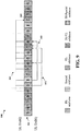
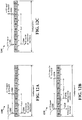
- FIG. 3 is a diagram 300 illustrating an example of a DL frame structure in LTE.
- a frame (10 ms) may be divided into 10 equally sized subframes. Each subframe may include two consecutive time slots.
- a resource grid may be used to represent two time slots, each time slot including a resource block.
- the resource grid is divided into multiple resource elements.
- a resource block contains 12 consecutive subcarriers in the frequency domain and 7 consecutive OFDM symbols in the time domain, for a total of 84 resource elements.
- For an extended cyclic prefix a resource block contains 12 consecutive subcarriers in the frequency domain and 6 consecutive OFDM symbols in the time domain, for a total of 72 resource elements.
- Some of the resource elements, indicated as R 302, 304, include DL reference signals (DL-RS).
- the DL-RS include Cell-specific RS (CRS) (also sometimes called common RS) 302 and UE-specific RS (UE-RS) 304.
- UE-RS 304 are transmitted on the resource blocks upon which the corresponding physical DL shared channel (PDSCH) is mapped.
- PDSCH physical DL shared channel
- the number of bits carried by each resource element depends on the modulation scheme. Thus, the more resource blocks that a UE receives and the higher the modulation scheme, the higher the data rate for the UE.
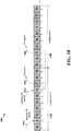
- FIG. 4 is a diagram 400 illustrating an example of an UL frame structure in LTE.
- the available resource blocks for the UL may be partitioned into a data section and a control section.
- the control section may be formed at the two edges of the system bandwidth and may have a configurable size.
- the resource blocks in the control section may be assigned to UEs for transmission of control information.
- the data section may include all resource blocks not included in the control section.
- the UL frame structure results in the data section including contiguous subcarriers, which may allow a single UE to be assigned all of the contiguous subcarriers in the data section.
- a UE may be assigned resource blocks 410a, 410b in the control section to transmit control information to an eNB.
- the UE may also be assigned resource blocks 420a, 420b in the data section to transmit data to the eNB.
- the UE may transmit control information in a physical UL control channel (PUCCH) on the assigned resource blocks in the control section.
- the UE may transmit data or both data and control information in a physical UL shared channel (PUSCH) on the assigned resource blocks in the data section.
- a UL transmission may span both slots of a subframe and may hop across frequency.
- a set of resource blocks may be used to perform initial system access and achieve UL synchronization in a physical random access channel (PRACH) 430.
- the PRACH 430 carries a random sequence and cannot carry any UL data/signaling.
- Each random access preamble occupies a bandwidth corresponding to six consecutive resource blocks.
- the starting frequency is specified by the network. That is, the transmission of the random access preamble is restricted to certain time and frequency resources. There is no frequency hopping for the PRACH.
- the PRACH attempt is carried in a single subframe (1 ms) or in a sequence of few contiguous subframes and a UE can make a single PRACH attempt per frame (10 ms).
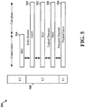
- FIG. 5 is a diagram 500 illustrating an example of a radio protocol architecture for the user and control planes in LTE.
- the radio protocol architecture for the UE and the eNB is shown with three layers: Layer 1, Layer 2, and Layer 3.
- Layer 1 (L1 layer) is the lowest layer and implements various physical layer signal processing functions.
- the L1 layer will be referred to herein as the physical layer 506.
- Layer 2 (L2 layer) 508 is above the physical layer 506 and is responsible for the link between the UE and eNB over the physical layer 506.
- the L2 layer 508 includes a media access control (MAC) sublayer 510, a radio link control (RLC) sublayer 512, and a packet data convergence protocol (PDCP) 514 sublayer, which are terminated at the eNB on the network side.
- MAC media access control
- RLC radio link control
- PDCP packet data convergence protocol
- the UE may have several upper layers above the L2 layer 508 including a network layer (e.g., IP layer) that is terminated at the PDN gateway 118 on the network side, and an application layer that is terminated at the other end of the connection (e.g., far end UE, server, etc.).
- IP layer e.g., IP layer
- the PDCP sublayer 514 provides multiplexing between different radio bearers and logical channels.
- the PDCP sublayer 514 also provides header compression for upper layer data packets to reduce radio transmission overhead, security by ciphering the data packets, and handover support for UEs between eNBs.
- the RLC sublayer 512 provides segmentation and reassembly of upper layer data packets, retransmission of lost data packets, and reordering of data packets to compensate for out-of-order reception due to hybrid automatic repeat request (HARQ).
- HARQ hybrid automatic repeat request
- the MAC sublayer 510 provides multiplexing between logical and transport channels.
- the MAC sublayer 510 is also responsible for allocating the various radio resources (e.g., resource blocks) in one cell among the UEs.
- the MAC sublayer 510 is also responsible for HARQ operations.
- the radio protocol architecture for the UE and eNB is substantially the same for the physical layer 506 and the L2 layer 508 with the exception that there is no header compression function for the control plane.
- the control plane also includes a radio resource control (RRC) sublayer 516 in Layer 3 (L3 layer).
- RRC sublayer 516 is responsible for obtaining radio resources (e.g., radio bearers) and for configuring the lower layers using RRC signaling between the eNB and the UE.
- FIG. 6 is a block diagram of an eNB 610 in communication with a UE 650 in an access network.
- upper layer packets from the core network are provided to a controller/processor 675.
- the controller/processor 675 implements the functionality of the L2 layer.
- the controller/processor 675 provides header compression, ciphering, packet segmentation and reordering, multiplexing between logical and transport channels, and radio resource allocations to the UE 650 based on various priority metrics.
- the controller/processor 675 is also responsible for HARQ operations, retransmission of lost packets, and signaling to the UE 650.
- the transmit (TX) processor 616 implements various signal processing functions for the L1 layer (i.e., physical layer).
- the signal processing functions include coding and interleaving to facilitate forward error correction (FEC) at the UE 650 and mapping to signal constellations based on various modulation schemes (e.g., binary phase-shift keying (BPSK), quadrature phase-shift keying (QPSK), M-phase-shift keying (M-PSK), M-quadrature amplitude modulation (M-QAM)).
- FEC forward error correction
- BPSK binary phase-shift keying
- QPSK quadrature phase-shift keying
- M-PSK M-phase-shift keying
- M-QAM M-quadrature amplitude modulation
- Each stream is then mapped to an OFDM subcarrier, multiplexed with a reference signal (e.g., pilot) in the time and/or frequency domain, and then combined together using an Inverse Fast Fourier Transform (IFFT) to produce a physical channel carrying a time domain OFDM symbol stream.
- the OFDM stream is spatially precoded to produce multiple spatial streams.
- Channel estimates from a channel estimator 674 may be used to determine the coding and modulation scheme, as well as for spatial processing.
- the channel estimate may be derived from a reference signal and/or channel condition feedback transmitted by the UE 650.
- Each spatial stream may then be provided to a different antenna 620 via a separate transmitter 618TX.
- Each transmitter 618TX may modulate an RF carrier with a respective spatial stream for transmission.
- each receiver 654RX receives a signal through its respective antenna 652.
- Each receiver 654RX recovers information modulated onto an RF carrier and provides the information to the receive (RX) processor 656.
- the RX processor 656 implements various signal processing functions of the L1 layer.
- the RX processor 656 may perform spatial processing on the information to recover any spatial streams destined for the UE 650. If multiple spatial streams are destined for the UE 650, they may be combined by the RX processor 656 into a single OFDM symbol stream.
- the RX processor 656 then converts the OFDM symbol stream from the time-domain to the frequency domain using a Fast Fourier Transform (FFT).
- FFT Fast Fourier Transform
- the symbols on each subcarrier, and the reference signal, are recovered and demodulated by determining the most likely signal constellation points transmitted by the eNB 610. These soft decisions may be based on channel estimates computed by the channel estimator 658. The soft decisions are then decoded and deinterleaved to recover the data and control signals that were originally transmitted by the eNB 610 on the physical channel. The data and control signals are then provided to the controller/processor 659.
- the controller/processor 659 implements the L2 layer.
- the controller/processor can be associated with a memory 660 that stores program codes and data.
- the memory 660 may be referred to as a computer-readable medium.
- the controller/processor 659 provides demultiplexing between transport and logical channels, packet reassembly, deciphering, header decompression, control signal processing to recover upper layer packets from the core network.
- the upper layer packets are then provided to a data sink 662, which represents all the protocol layers above the L2 layer.
- Various control signals may also be provided to the data sink 662 for L3 processing.
- the controller/processor 659 is also responsible for error detection using an acknowledgement (ACK) and/or negative acknowledgement (NACK) protocol to support HARQ operations.
- ACK acknowledgement
- NACK negative acknowledgement
- a data source 667 is used to provide upper layer packets to the controller/processor 659.
- the data source 667 represents all protocol layers above the L2 layer.
- the controller/processor 659 implements the L2 layer for the user plane and the control plane by providing header compression, ciphering, packet segmentation and reordering, and multiplexing between logical and transport channels based on radio resource allocations by the eNB 610.
- the controller/processor 659 is also responsible for HARQ operations, retransmission of lost packets, and signaling to the eNB 610.
- Channel estimates derived by a channel estimator 658 from a reference signal or feedback transmitted by the eNB 610 may be used by the TX processor 668 to select the appropriate coding and modulation schemes, and to facilitate spatial processing.
- the spatial streams generated by the TX processor 668 may be provided to different antenna 652 via separate transmitters 654TX. Each transmitter 654TX may modulate an RF carrier with a respective spatial stream for transmission.
- the UL transmission is processed at the eNB 610 in a manner similar to that described in connection with the receiver function at the UE 650.
- Each receiver 618RX receives a signal through its respective antenna 620.
- Each receiver 618RX recovers information modulated onto an RF carrier and provides the information to a RX processor 670.
- the RX processor 670 may implement the L1 layer.
- the controller/processor 675 implements the L2 layer.
- the controller/processor 675 can be associated with a memory 676 that stores program codes and data.
- the memory 676 may be referred to as a computer-readable medium.
- the controller/processor 675 provides demultiplexing between transport and logical channels, packet reassembly, deciphering, header decompression, control signal processing to recover upper layer packets from the UE 650.
- Upper layer packets from the controller/processor 675 may be provided to the core network.
- the controller/processor 675 is also responsible for error detection using an ACK and/or NACK protocol to support HARQ operations.
- TDD DL/UL subframe configurations may be dynamically changed based on traffic needs.
- Table 1 shows example subframe configurations.
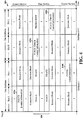
- TDD UL/DL subframe configurations Uplink-downlink Configuration Downlink-to- Uplink Switch-point periodicity Subframe number 0 1 2 3 4 5 6 7 8 9 0 5 ms D S U U U D S U U U 1 5 ms D S U U D D S U U D 2 5 ms D S U D D D S U D D 3 10 ms D S U U U D D D D D D 4 10 ms D S U U D D D D D D 5 10 ms D S U D D D D D D D D 6 5 ms D S U U U U D S U U U D S U U D
- a current subframe configuration may be dynamically changed to another subframe configuration that includes more DL subframes. For example, in such a case, if a current subframe configuration is subframe configuration #1 with 6 DL subframes and 4 UL subframes, the subframe configuration may be changed to subframe configuration #5 with 9 DL subframes and 1 UL subframe (thus having more DL subframes than subframe configuration #1), in order to adapt to the need for a large data burst on DL.
- Each cell may adopt a subframe configuration independently. Multiple cells adopting different subframe configurations may introduce interference between UEs in different cells.
- a UE in a first cell with one subframe configuration and another UE in a second cell with a different subframe configuration may experience UE-to-UE interference.
- the UE-to-UE interference may exist in a subframe that is configured for one type of communication in the first cell and is configured for another type of communication in the second cell.
- the UE-to-UE interference may exist in a subframe that is used as a DL subframe in the first cell and is used as a UL subframe in the second cell.
- a base station to UE (BS-to-UE) interference may exist.
- FIG. 7 is an example diagram 700 illustrating two cells utilizing different subframe configurations.
- an eNB A 710 having Cell A 720 utilizes subframe configuration #1 712.
- An eNB B 750 having Cell B 760 utilizes subframe configuration #2 752.
- a first UE 722 in Cell A 720 sends a UL signal 732 to eNB A 710, and a second UE 724 in Cell A 720 sends a UL signal 734.
- a third UE 762 in Cell B 760 receives a downlink signal 772 and a fourth UE 764 in Cell B 760 receives a downlink signal 774.
- FIG. 7 illustrates a downlink signal 774.
- UE-to-UE interference exists between the second UE 724 of Cell A 720 and the third UE 762 of Cell B 760.
- the UE-to-UE interference exists in subframe #3 and subframe #8 because subframes #3 and 8 are flexible subframes that are configured for different types of communication between the eNB A 710 and eNB B 750, where subframes #3 and 8 are UL subframes for eNB A 710 and are DL subframes for eNB B 750.
- the type of communication e.g., UL or DL
- BS-to-UE interference between the eNB A 710 and at least one of the first UE 722 and the second UE 724 may exist and BS-to-UE interference between eNB B 750 and at least one of the third UE 762 and the fourth UE 764 may exist.
- FIG. 8 is an example diagram 800 illustrating fixed subframes and flexible subframes in the subframe configurations.
- Subframe #s 0, 1, and 2 are fixed subframes 802.
- Subframe #s 3 and 4 are flexible subframes.
- Subframe #s 5 and 6 are fixed subframes.
- Subframe #s 7, 8, and 9 are flexible subframes.
- the fixed subframes are configured for the same type of communication throughout the configurations #0 to 6.
- the flexible subframes may be configured for different types of communication throughout the configurations #0 to 6. Interference in flexible subframes is different from interference in fixed subframes. For example, as discussed above, UE-to-UE interference may exist in a flexible subframe and BS-to-UE interference may exist in a fixed subframe.
- the CSI may include a channel quality indicator (CQI), a precoding matrix indicator (PMI), and a rank indicator (RI) (e.g., CQI/PMI/RI).
- CQI channel quality indicator
- PMI precoding matrix indicator
- RI rank indicator
- 3GPP supports both a periodic CQI feedback and an aperiodic CQI feedback for the UEs in the eIMTA.
- the periodic CQI may be supported via an eNB implementation through a special configuration.
- the aperiodic CQI may be supported by a timeline/reference subframe design as described infra.
- the UE may transmit aperiodic CSI including the aperiodic CQI to the eNB via UL at subframe m + k, where m denotes a subframe where a CSI request has been received at the UE.
- the CSI request may be received in the downlink control information (DCI) format 0/4 in PDCCH with a CSI request field set to 1.
- DCI downlink control information
- k is provided in a specification as shown in Table 2 below.
- a reference subframe that is used for CQI estimation is generally subframe m, which is the subframe where the UE has received the CSI request (e.g., in the DCI format 0/4).
- Table 2. k for TDD UL-DL subframe configurations Uplink-downlink Configuration Subframe number 0 1 2 3 4 5 6 7 8 9 0 4 6 4 6 1 6 4 6 4 2 4 4 3 4 4 4 4 4 5 4 6 7 7 7 5
- one or more DL/UL subframe configurations may be defined as reference configurations for several physical layer operations.
- a DL reference subframe configuration may be defined based on one of the subframe configurations and a UL reference subframe configuration may be defined based on another one of the subframe configurations, such that the DL reference subframe configuration is used for DL HARQ operations and the UL reference subframe configuration is used for UL HARQ operations.
- DL HARQ operations may be based on DL/UL subframe configuration #5, regardless of an actual DL/UL subframe configuration in use in a frame (or half a frame).
- the DL HARQ timing may be based on the subframe configuration #5 with eight DL subframes (#s 0, 1, and 3-9) and one UL subframe (#3) (e.g., a 8:1 DL/UL subframe configuration).
- a UL HARQ operation can be based on DL/UL subframe configuration #0, regardless of an actual DL/UL subframe configuration in use in a frame (or half a frame).
- the UL HARQ timing may be based on the subframe configuration #0 with four DL subframes (#s 0, 1, 5, and 6) and six UL subframes (#s 2-4 and 7-9) (e.g., a 4:6 DL/UL subframe configuration).
- FIG. 9 is an example HARQ operation 900 of a DL HARQ operation and a UL HARQ operation with subframes 901 according to DL and UL reference subframe configurations.
- the DL reference subframe configuration utilizes subframe configuration #5 for the DL HARQ operation
- the UL reference subframe configuration utilizes subframe configuration #0 for the UL HARQ operation.
- subframes #0 and 5 are fixed as DL subframes for both the DL and UL HARQ operations
- subframe #1 is fixed as a special subframe for both the DL and UL HARQ operations
- subframe #2 is fixed as a UL subframe for both the DL and UL HARQ operations.
- Each of subframes #3, 4, 7, 8, and 9 is a DL/UL subframe that is used as a UL subframe or a DL subframe depending on whether the operation is the DL HARQ operation or the UL HARQ operation.
- subframes #3, 4, 7, 8, and 9 are used as DL subframes for the DL HARQ operation based on the subframe configuration #5
- subframes #3, 4, 7, 8, and 9 are used as UL subframes for the UL HARQ operation based on the subframe configuration #0.
- Subframe #6 is a DL/Special subframe that is used as a DL subframe or a special subframe depending on whether the operation is the DL HARQ operation or the UL HARQ operation.
- the UE may receive DL data at subframes # 9, 0, 1, 3, 4, 5, 6, 7, and 8 and may transmit an UL response at subframe #2 (913). Further, as illustrated in FIG. 9 , during a first UL HARQ operation 951, the UE may receive DL control at subframes #0 and transmit associated UL information at subframes #4 and 7. During a second UL HARQ operation 953, the UE may receive DL control at subframe 1 and transmit associated UL information at subframes #7 and 8.
- a timeline for the aperiodic CSI (A-CSI) report may reuse the HARQ UL reference configuration to send the aperiodic CSI report.
- the eNB sends the CSI request in a fixed DL subframe.
- subframe configuration #0 is used as the UL reference configuration
- the eNB sends the CSI request in fixed DL subframes such as subframes #s 0, 1, 5 and 6.
- FIG. 10 is an example diagram 1000 illustrating an example of an A-CSI design. In FIG. 10 , when proceeding from a first time period 1010 to a second time period 1050, the subframe configuration is changed from subframe configuration #2 of the first time period 1010 to subframe configuration #1 of the second time period 1050.
- the CSI request may be sent in subframes #s 0, 1, 5 and/or 6, regardless of the subframe configuration of each time period.
- the eNB sends a first A-CSI request at subframe #1.
- the UE measures a first CSI at subframe #1, and subsequently sends at subframe #7 a first CSI report including the measured first CSI in the first time period 1010.
- the eNB sends a second A-CSI request at subframe #6.
- the UE measures a second CSI at subframe #6 in the first time period 1010, and subsequently sends a second CSI report including the measured second CSI at subframe #2 in the second time period 1050.
- the eNB generally sends the CSI request to the UE in a fixed subframe and the UE measures the CSI in the fixed subframe where the CSI request is sent.
- the reference subframe where the CSI is measured is generally the fixed subframe where the CSI request is sent.
- the UE may receive the CSI request in downlink control information (DCI) format 0/4.
- DCI downlink control information
- the CSI measured in the fixed subframe is then reported to the eNB.
- the CSI in flexible subframes may not be reported while the CSI in the fixed subframe may be reported to the eNB.
- the reference subframe is the subframe the UE receives a trigger indicator in DCI format 0/4.
- the following approaches may be utilized to determine a reference subframe at a flexible subframe and/or a fixed subframe, in order to enable measuring the CSI at a fixed subframe as well as at a flexible subframe.
- the UE When the UE receives an A-CSI request, the UE measures the channel and/or the interference, computes a CQI/PMI/RI based on the measured channel and/or the interference, and sends an A-CSI report including the CQI/PMI/RI.
- channel measurements and interference measurements for computing the CSI value e.g., the CQI/PMI/RI
- the reference subframe may be a fixed subframe or a flexible subframe, depending on the subframe configuration.
- the UE may determine a location and a type (e.g., fixed subframe or flexible subframe) of the reference subframe based on a report delay between an A-CSI request DL subframe and an A-CSI report UL subframe and/or based on the A-CSI report UL subframe.
- a type e.g., fixed subframe or flexible subframe
- Three cases may exist in determining the reference subframe. Assume that n is the A-CSI report UL subframe, x is the report delay, and n - x is the A-CSI request DL subframe.
- the reference subframe may be expressed as n - n CQI_ref , where n CQI_ref is a reference delay between the reference subframe and the A-CSI report UL subframe.
- the location and the type of the reference subframe n - n CQI_ref may be determined according to the following three cases, based on at least one of the A-CSI report UL subframe n, the A-CSI request DL subframe n - x, the reference delay n CQI_ref , and the report delay x.
- n CQI_ref 4 subframes.
- the reference subframe n - n CQI_ref is the same as the A-CSI request DL subframe, and thus the reference subframe is a fixed DL subframe.
- the UE measures the channel and the interference based on the fixed subframe at the reference subframe, and sends the A-CSI report for the fixed DL subframe based on the channel and the interference measurements.
- n CQI_ref 4 subframes.
- the reference subframe n - n CQI_ref is a flexible DL subframe.
- n CQI_ref report delay x.
- the reference subframe n - n CQI_ref is a fixed DL subframe.
- FIGs. 11A-11C are example diagrams illustrating the first approach.
- FIG. 11A is an example diagram 1100 illustrating an example of the first case of the first approach.
- the example diagram 1100 is based on subframe configuration #0.
- An A-CSI request 1102 is received at subframe #0, and an A-CSI report UL subframe n to send an A-CSI report 1104 is subframe #4.
- the reference delay n CQI_ref is also 4 subframes.
- the location of the reference subframe n - n CQI_ref is the same as a location of the A-CSI request DL subframe.
- the A-CSI request DL subframe is subframe #0 and is a fixed subframe. Therefore, in FIG. 11A , the UE measures at 1106 the channel and the interference at subframe #0 based on the fixed subframe. Subsequently, the UE computes a CQI/PMI/RI based on the measured channel and interference, and sends at subframe #4 the A-CSI report 1104 including the CQI/PMI/RI for the fixed DL subframe.
- FIG. 11B is an example diagram 1130 illustrating an example of the second case of the first approach.
- the example diagram 1130 is based on subframe configuration #2
- An A-CSI request 1132 is received at subframe #1, and an A-CSI report UL subframe n to send an A-CSI report 1134 is subframe #7.
- a report delay x between the A-CSI request 1132 and the A-CSI report 1134 is greater than 4 subframes and a subframe corresponding to n - 4 is a DL subframe, which is subframe #3.
- the reference delay n CQI_ref is also 4 subframes.
- the reference subframe n - n CQI_ref is located at subframe #3, which is a flexible DL subframe.
- the UE measures at 1136 the channel and the interference at subframe #3 based on the flexible subframe.
- the UE computes a CQI/PMI/RI based on the measured channel and interference, and sends at subframe #7 the A-CSI report 1134 including the CQI/PMI/RI for the flexible DL subframe.
- FIG. 11C is an example diagram 1160 illustrating an example of the third case of the first approach.
- the example diagram 1160 is based on subframe configuration #1
- An A-CSI request 1162 is received at subframe #1, and an A-CSI report UL subframe n to send an A-CSI report 1164 is subframe #7.
- a report delay x between the A-CSI request 1162 and the A-CSI report 1164 is greater than 4 subframes and a subframe corresponding to n - 4 is a UL subframe, which is subframe #3.
- the reference delay n CQI_ref is equal to the report delay x.
- the reference subframe n - n CQI_ref is located at subframe #1, which is a fixed subframe and the A-CSI request DL subframe.
- the UE measures at 1166 the channel and the interference at subframe #1 based on the fixed DL subframe.
- the UE computes a CQI/PMI/RI based on the measured channel and interference, and sends at subframe #7 the A-CSI report 1134 including the CQI/PMI/RI for the fixed DL subframe.
- channel quality measurements and the interference measurements may be performed in different DL subframes or in the same DL subframe.
- channel quality measurements are performed at a subframe (e.g., an A-CSI request DL subframe) where an A-CSI request is received.
- the interference measurements are performed at a reference subframe that may be a fixed DL subframe or a flexible DL subframe, depending on the subframe configuration.
- the UE may determine a location and a type (e.g., fixed subframe or flexible subframe) of the reference subframe based on a report delay between an A-CSI request DL subframe and an A-CSI report UL subframe and/or based on the A-CSI report UL subframe.
- n is the A-CSI report UL subframe
- x is the report delay
- n - x is the A-CSI request DL subframe.
- the location and the type of the reference subframe n - n CQI_ref may be determined according to the following three cases, where n CQI_ref is a reference delay between the reference subframe and the A-CSI report UL subframe.
- n CQI_ref 4 subframes.
- the reference subframe n - n CQI_ref for interference measurements is the same as the A-CSI request DL subframe, and thus both the channel and the interference are measured at the A-CSI request DL subframe, which is a fixed subframe.
- the UE measures the channel and the interference based on the fixed DL subframe at the reference subframe, and sends the A-CSI report for the fixed DL subframe based on the channel and/or the interference measurements.
- n CQI_ref 4 subframes.
- the reference subframe n - n CQI_ref for interference measurements is a flexible DL subframe, and thus the UE sends the A-CSI report for the flexible DL subframe.
- the channel is measured at the A-CSI request DL subframe while the interference is measured at a reference subframe that is different from the A-CSI request DL subframe.
- the UE sends the A-CSI report based on the channel measurement at one subframe (e.g., the A-CSI request DL subframe) and the interference measurement at another subframe (e.g., the reference subframe n - n CQI_ref ).
- the reference subframe n - n CQI_ref for interference measurements may be the same as the A-CSI request DL subframe, and thus both the channel and the interference are measured at the A-CSI request DL subframe.
- the reference subframe n - n CQI_ref for interference measurements is a fixed subframe.
- the UE measures the channel and the interference based on the fixed DL subframe at the reference subframe, and sends the A-CSI report for the fixed DL subframe based on the channel and the interference measurements.
- FIGs. 12A-12C are example diagrams illustrating the second approach.
- FIG. 12A is an example diagram 1200 illustrating an example of the first case of the second approach.
- the example diagram 1200 is based on subframe configuration #0, and an A-CSI report UL subframe n to send an A-CSI report 1204 is subframe #4.
- the channel measurements are performed at subframe #0, which is an A-CSI request DL subframe where an A-CSI request 1202 is received.
- the reference delay n CQI_ref is also 4 subframes.
- the location of the reference subframe n - n CQI_ref for interference measurements is the same as a location of the A-CSI request DL subframe.
- the A-CSI request DL subframe is subframe #0 and is a fixed subframe. Therefore, in FIG. 12A , the UE measures at 1206 the channel and the interference at subframe #0 based on the fixed subframe. Subsequently, the UE computes a CQI/PMI/RI based on the measured channel and interference, and sends at subframe #4 the A-CSI report 1204 including the CQI/PMI/RI for the fixed DL subframe.
- FIG. 12B is an example diagram 1230 illustrating an example of the second case of the second approach.
- the example diagram 1230 is based on subframe configuration #2, and an A-CSI report UL subframe n to send an A-CSI report 1234 is subframe #7.
- the channel measurements are performed at subframe #1, which is an A-CSI request DL subframe where an A-CSI request 1232 is received.
- a report delay x between the A-CSI request 1232 and the A-CSI report 1234 is greater than 4 subframes and a subframe corresponding to n - 4 is a DL subframe, which is subframe #3.
- the reference delay n CQI_ref is also 4 subframes.
- the reference subframe n - n CQI_ref is located at subframe #3, which is a flexible DL subframe.
- the UE measures at 1236 the interference at subframe #3 based on the flexible subframe, and measures at 1238 the channel at subframe #1 based on the fixed subframe.
- the UE computes a CQI/PMI/RI based on the measured channel and interference, and sends at subframe #7 the A-CSI report 1234 including the CQI/PMI/RI for the flexible DL subframe.
- FIG. 12C is an example diagram 1260 illustrating an example of the third case of the second approach.
- the example diagram 1260 is based on subframe configuration #1.
- An A-CSI request 1262 is sent at subframe #1, and an A-CSI report UL subframe n to send an A-CSI report 1264 is subframe #7.
- the channel measurements are performed at subframe #1, which is an A-CSI request DL subframe where an A-CSI request 1262 is received.
- a report delay x between the A-CSI request 1262 and the A-CSI report 1264 is greater than 4 subframes and a subframe corresponding to n - 4 is a UL subframe, which is subframe #3.
- the reference delay n CQI_ref is equal to the report delay x.
- the reference subframe n - n CQI_ref for interference measurements is located at subframe #1, which is a fixed subframe and the A-CSI request DL subframe.
- the UE measures at 1266 the channel and the interference at subframe #1 based on the fixed subframe.
- the UE computes a CQI/PMI/RI based on the measured channel and interference, and sends at subframe #7 the A-CSI report 1264 including the CQI/PMI/RI for the fixed DL subframe.
- CSI values measured in multiple reference subframes may be combined and reported to the eNB, where each CSI includes a respective CQI/PMI/RI.
- the UE may determine whether to report a single CSI or multiple CSIs based on the A-CSI report UL subframe and the report delay. The determination as to whether to report a single CSI or multiple CSIs may be further based on a location of the A-CSI request downlink subframe. If the UE determines to report multiple CSIs, the UE may, for example, compute a first CSI corresponding to a first reference subframe and compute a second CSI corresponding to a second reference subframe, and then combine the first and second CSIs to report them together.
- the UE may measure a channel and/or interference at the first reference subframe that is a flexible subframe, in order to compute the first CSI, and may also measure a channel and/or interference at the second reference subframe that is a fixed subframe, in order to compute the second CSI. Subsequently, the UE may combine (e.g., multiplex) the first and second CSIs to send the first and second CSIs in the same CSI report.
- the UE may determine a location and a type (e.g., fixed subframe or flexible subframe) of each reference subframe based on a report delay between an A-CSI request DL subframe and an A-CSI report UL subframe and/or based on the A-CSI report UL subframe.
- channel measurements and interference measurements for computing each CSI value are performed in the same reference subframe, which is a DL subframe.
- n is the A-CSI report UL subframe
- x is the report delay
- n - x is the A-CSI request DL subframe.
- n CQI_ref1 is a reference delay between the first reference subframe and the A-CSI report UL subframe n
- n CQI_ref2 is a reference delay between the second reference subframe and the A-CSI report UL subframe n .
- n CQI_ref2 4 subframes and the UE will not report a CSI of a flexible subframe.
- the second reference subframe n - n CQI_ref2 is the same as the A-CSI request DL subframe, and thus the second reference subframe n - n CQI_ref2 is a fixed subframe.
- the UE measures the channel and the interference based on the fixed subframe at the second reference subframe, and sends the A-CSI report for the fixed subframe based on the channel and the interference.
- the UE combines a flexible subframe CSI of the first reference subframe n - n CQI_ref1 that is a flexible subframe, and a fixed subframe CSI of the second reference subframe n - n CQI_ref2 that is a fixed subframe, and subsequently sends the A-CSI report with the flexible subframe CSI and the fixed subframe CSI in a subframe n .
- the second reference subframe n - n CQI_ref2 may be the same as the A-CSI request DL subframe, which is a fixed subframe.
- the UE measures the channel and the interference based on the fixed subframe at the second reference subframe, and sends the A-CSI report for the fixed subframe based on the channel and the interference. It is noted that, in the third case, channel and interference based on a flexible subframe may not be measured or reported.
- channel quality measurements and the interference measurements for each CSI are performed in different DL subframes.
- channel measurements for each CSI are performed at a subframe (e.g., an A-CSI request DL subframe) where an A-CSI request is received.
- the interference measurements are performed at a reference frame that may be a fixed subframe or a flexible subframe, depending on the subframe configuration.
- the UE may determine a location and a type (e.g., fixed subframe or flexible subframe) of the reference subframe based on a report delay between an A-CSI request DL subframe and an A-CSI report UL subframe and/or based on the A-CSI report UL subframe.
- n is the A-CSI report UL subframe
- x is the report delay
- n - x is the A-CSI request DL subframe.
- the location and the type of a first reference subframe n - n CQI_ref1 for a flexible subframe CSI and/or a second reference subframe n - n CQI_ref2 for a fixed subframe CSI may be determined according to the following three cases, where n CQI_ref1 is a reference delay between the first reference subframe and the A-CSI report UL subframe, and n CQI_ref2 is a reference delay between the second reference subframe and the A-CSI report UL subframe.
- n CQI_ref2 4 subframes and the UE will not report a CSI of a flexible subframe.
- the second reference subframe n - n CQI_ref2 for the interference measurements is a fixed subframe and is the same as the A-CSI request DL subframe.
- the UE measures both the channel and the interference for the fixed subframe CSI based on the fixed subframe at the A-CSI request DL subframe, sends the A-CSI report for the fixed subframe based on the channel and the interference.
- the channel for a flexible subframe CSI is measured at the A-CSI request DL subframe while the interference for the flexible subframe CSI is measured at a separate reference subframe, in order to compute the flexible subframe CSI of the first reference subframe n - n CQI_ref1 .
- the channel and the interference for a fixed subframe CSI are measured at the A-CSI request DL subframe, in order to compute the fixed subframe CSI of the second reference subframe n - n CQI_ref2 .
- the UE subsequently combines the flexible subframe CSI corresponding to the first reference subframe n - n CQI_ref1 that is a flexible subframe, and the fixed subframe CSI corresponding to the second reference subframe n - n CQI_ref2 that is a fixed subframe, and sends the A-CSI report with the flexible subframe CSI and the fixed subframe CSI in a subframe n.
- n CQI_ref2 report delay x and the UE will not report a CSI of a flexible subframe.
- the second reference subframe n - n CQI_ref2 for the interference measurements may be the same as the A-CSI request DL subframe, which is a fixed subframe, and thus both the channel and the interference for the fixed subframe CSI may be measured at the A-CSI request DL subframe. Therefore, the UE measures the channel and the interference based on the fixed subframe, and sends the A-CSI report for the fixed subframe based on the channel and the interference
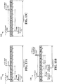
- FIGs. 13A-13C are example diagrams illustrating a first scenario of the third approach.
- FIG. 13A is an example diagram 1300 illustrating an example of the first case of the third approach's first scenario.
- the example diagram 1300 is based on subframe configuration #0.
- An A-CSI request 1302 is received at subframe #0, and an A-CSI report UL subframe n to send an A-CSI report 1304 is subframe #4.
- the reference delay n CQI_ref2 is also 4 subframes and the UE will not report a CSI of a flexible subframe.
- the location of the second reference subframe n - n CQI_ref2 is the same as a location of the A-CSI request DL subframe, at subframe #0.
- the A-CSI request DL subframe is subframe #0 and is a fixed subframe. Therefore, in FIG. 13A , the UE measures at 1306 the channel and the interference at subframe #0 based on the fixed subframe. Subsequently, the UE computes a fixed subframe CSI based on the measured channel and interference, and sends at subframe #4 an A-CSI report 1304 including the fixed subframe CSI for the fixed subframe.
- FIG. 13B is an example diagram 1330 illustrating an example of the second case of the third approach's first scenario.
- the example diagram 1330 is based on subframe configuration #2.
- An A-CSI request 1332 is received at subframe #1, and an A-CSI report UL subframe n to send an A-CSI report 1334 is subframe #7.
- a report delay x between the A-CSI request 1332 and the A-CSI report 1334 is greater than 4 subframes and a subframe corresponding to n - 4 is a DL subframe, which is subframe #3.
- the first reference delay n CQI_ref1 is 4 subframes and the second reference delay n CQI_ref2 is equal to the report delay x .
- the first reference subframe n - n CQI_ref1 is located at subframe #3, which is a flexible subframe
- the second reference subframe n - n CQI_ref2 is located at subframe #1, which is a fixed subframe.
- the UE measures at 1336 the channel and the interference at subframe #3 based on the flexible subframe to compute a flexible subframe CSI
- the UE combines the flexible subframe CSI and the fixed subframe CSI, and sends at subframe #7 an A-CSI report 1334 including the flexible subframe CSI and the fixed subframe CSI.
- FIG. 13C is an example diagram 1360 illustrating an example of the third case of the third approach's first scenario.
- the example diagram 1360 is based on subframe configuration #1.
- An A-CSI request 1362 is received at subframe #1, and an A-CSI report UL subframe n to send an A-CSI report 1364 is subframe #7.
- a report delay x between the A-CSI request 1362 and the A-CSI report 1364 is greater than 4 subframes and a subframe corresponding to n - 4 is a UL subframe, which is subframe #3.
- the reference delay n CQI_ref2 is equal to the report delay x, and the UE will not report a CSI of a flexible subframe.
- the second reference subframe n - n CQI_ref2 is located at subframe #1, which is a fixed subframe and the A-CSI request DL subframe.
- the UE measures at 1366 the channel and the interference at subframe #1 based on the fixed subframe.
- the UE computes a CSI based on the measured channel and interference, and sends at subframe #7 an A-CSI report 1334 including the CSI for the fixed subframe.
- FIGs. 14A-14C are example diagrams illustrating a second scenario of the third approach.
- FIG. 14A is an example diagram 1400 illustrating an example of the first case of the third approach's second scenario.
- the example diagram 1400 is based on subframe configuration #0, and an A-CSI report UL subframe n to send an A-CSI report 1404 is subframe #4.
- the channel measurements are performed at subframe #0, which is an A-CSI request DL subframe where an A-CSI request 1402 is received.
- subframe #0 is an A-CSI request DL subframe where an A-CSI request 1402 is received.
- the reference delay n CQI_ref2 is also 4 subframes and the UE will not report a CSI of a flexible subframe.
- the location of the second reference subframe n - n CQI_ref2 for interference measurements is the same as a location of the A-CSI request DL subframe, at subframe #0.
- the A-CSI request DL subframe is subframe #0 and is a fixed subframe. Therefore, in FIG. 14A , the UE measures at 1406 the channel and the interference at subframe #0 based on the fixed subframe. Subsequently, the UE computes a fixed subframe CSI based on the measured channel and interference, and sends at subframe #4 an A-CSI report 1404 including the fixed subframe CSI for the fixed subframe.
- FIG. 14B is an example diagram 1430 illustrating an example of the second case of the third approach's second scenario.
- the example diagram 1430 is based on subframe configuration #2, and an A-CSI report UL subframe n to send an A-CSI report 1434 is subframe #7.
- a report delay x between an A-CSI request 1432 and the A-CSI report 1434 is greater than 4 subframes and a subframe corresponding to n - 4 is a DL subframe, which is subframe #3.
- the first reference delay n CQI_ref1 is 4 subframes and the second reference delay n CQI_ref2 is equal to the report delay x.
- the first reference subframe n - n CQI_ref1 is located at subframe #3, which is a flexible subframe
- the second reference subframe n - n CQI_ref2 is located at subframe #1, which is a fixed subframe.
- the UE receives the A-CSI request 1432, in order to compute a flexible subframe CSI
- the UE performs at 1438 the channel measurements at subframe #1, which is an A-CSI request DL subframe where the A-CSI request 1432 is received, based on the fixed subframe, and further performs at 1436 the interference measurements at subframe #3, which is the first reference subframe n - n CQI_ref1 for interference measurements, based on the flexible subframe.
- the UE After the UE receives an A-CSI request 1432, in order to compute a fixed subframe CSI, the UE performs at 1438 the channel measurements and the interference measurements at subframe #1, which is the A-CSI request DL subframe, based on the fixed subframe. Subsequently, the UE combines the flexible subframe CSI and the fixed subframe CSI, and sends at subframe #7 the A-CSI report 1434 including the flexible subframe CSI and the fixed subframe CSI.
- FIG. 14C is an example diagram 1460 illustrating an example of the third case of the third approach's second scenario.
- the example diagram 1460 is based on subframe configuration #1, and an A-CSI report UL subframe n to send an A-CSI report 1464 is subframe #7.
- the channel measurements are performed at subframe #1, which is an A-CSI request DL subframe where an A-CSI request 1462 is received.
- a report delay x between the A-CSI request 1462 and the A-CSI report 1464 is greater than 4 subframes and a subframe corresponding to n - 4 is a UL subframe, which is subframe #3.
- the reference delay n CQI_ref2 for interference measurements is equal to the report delay x, and the UE will not report a CSI of a flexible subframe.
- the second reference subframe n - n CQI_ref2 for interference measurements is located at subframe #1, which is a fixed subframe and the A-CSI request DL subframe.
- the UE measures at 1466 the channel and the interference at subframe #1 based on the fixed subframe.
- the UE computes a CSI based on the measured channel and interference, and sends at subframe #7 an A-CSI report 1464 including the CSI for the fixed subframe.
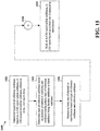
- FIG. 15 is a flow chart 1500 of a method of wireless communication.
- the method may be performed by a UE.
- the UE determines a location of a reference subframe based on an A-CSI report uplink subframe, an A-CSI request downlink subframe, a reference delay, and a report delay.
- the reference delay is a first delay value before the A-CSI report uplink subframe
- the report delay is a second delay value between the A-CSI request downlink subframe and the A-CSI report uplink subframe.
- the UE determines a type of the reference subframe based on the location of the reference subframe and a subframe configuration, the type of the reference subframe being a flexible subframe or a fixed subframe.
- the location and the type of the reference subframe n - n CQI_ref may be determined based on at least one of the A-CSI report UL subframe n, the A-CSI request DL subframe n - x, the reference delay n CQI_ref , and the report delay x.
- the reference subframe may be a fixed subframe or a flexible subframe, depending on the subframe configuration.
- the UE measures at least one of a channel or interference based on the reference subframe and the type of the reference subframe. As discussed supra, at least one of a channel or interference is measured at the reference subframe based on the type of the reference subframe.
- the UE may perform the method illustrated in FIG. 16 . Further explanations are provided infra.
- the UE sends, at the A-CSI report uplink subframe, an A-CSI report based on the at least one of the channel or the interference. For example, as discussed supra, the UE sends an A-CSI report including the CQI/PMI/RI that is based on the measured channel and/or the interference.
- the reference subframe is located a number of subframes prior to the A-CSI report uplink subframe, where the number of subframes is based on either the first delay value or the second delay value.
- the first delay value of the reference delay corresponds to four subframes.
- the reference subframe may be expressed as n - n CQI_ref , where n CQI_ref is a reference delay between the reference subframe and the A-CSI report UL subframe.
- the reference delay n CQI_ref is 4 subframes
- the reference delay n CQI_ref is the report delay x.
- the channel and the interference are measured at the reference subframe when the report delay corresponds to four subframes, the reference subframe corresponding to the A-CSI request downlink subframe.
- the channel and interference are measured based on the type of the reference subframe that is the fixed subframe. For example, referring back to FIG. 11A , because a report delay x between the A-CSI request 1102 and the A-CSI report 1104 is 4 subframes, the reference delay n CQI_ref is also 4 subframes.
- the UE measures at 1106 the channel and the interference at subframe #0 based on the fixed subframe.
- the reference subframe is located four subframes prior to the A-CSI report uplink subframe when the report delay is greater than four subframes and a subframe located four subframes prior to the A-CSI report uplink subframe is a downlink subframe.
- the channel and interference may be measured based on the type of the reference subframe that is the flexible subframe. For example, referring back to FIG.
- a report delay x between the A-CSI request 1132 and the A-CSI report 1134 is greater than 4 subframes and a subframe corresponding to n - 4 is a DL subframe, which is subframe #3, and thus as a result, the reference delay n CQI_ref is also 4 subframes.
- the UE measures at 1136 the channel and the interference at the reference subframe (subframe #3) based on the flexible subframe.
- the channel may be measured at the A-CSI request downlink subframe and the interference is measured at the reference subframe that is located four subframes prior to the A-CSI report uplink subframe.
- the interference may be measured based on the type of the reference subframe that is the flexible subframe and the channel is measured based on the type of the A-CSI request downlink subframe that is the fixed subframe.
- the UE measures at 1236 the interference at the reference subframe (subframe #3) based on the flexible subframe, and measures at 1238 the channel at the A-CSI request DL subframe (subframe #1) based on the fixed subframe.
- the reference subframe corresponds to the A-CSI request downlink subframe when the report delay is greater than four subframes and a subframe located four subframes prior to the A-CSI report uplink subframe is an uplink subframe or an MBSFN subframe.
- the channel and interference are measured based on the type of the A-CSI request downlink subframe that is a fixed subframe. For example, referring back to FIG.
- a report delay x between the A-CSI request 1162 and the A-CSI report 1164 is greater than 4 subframes and a subframe corresponding to n - 4 is a UL subframe, which is subframe #3, and as a result, the reference delay n CQI_ref is equal to the report delay x.
- the UE measures at 1166 the channel and the interference at subframe #1 based on the fixed subframe.
- FIG. 16 is a flow chart 1600 of a method of wireless communication expanding from the flow chart 1500 of FIG. 15 .
- the method may be performed by a UE.
- the UE determines, based on the A-CSI report uplink subframe and the report delay, to measure at least one of a second channel or second interference.
- the UE determines a location of a second reference subframe based on the A-CSI request downlink subframe.
- the UE measures at least one of the second channel or the second interference based on the second reference subframe.
- the A-CSI report sent at the A-CSI report uplink subframe at 1510 may include a CQI based on the at least one of the channel or the interference and the at least one of the second channel or the second interference.
- the determination to measure the at least one of the second channel or the second interference is further based on a location of the A-CSI request downlink subframe.
- the UE may determine whether to report a single CSI or multiple CSIs based on the A-CSI report UL subframe and the report delay, where each CSI includes a respective CQI/PMI/RI. If the UE determines to report multiple CSIs, the UE may measure a channel and/or interference at the first subframe that is a fixed reference subframe, in order to compute a first CSI, and may also measure a channel and/or interference at the second reference subframe that is a flexible subframe, in order to compute the second CSI. Subsequently, as discussed supra, the UE may combine (e.g., multiplex) the first and second CSIs to send the first and second CSIs in the same CSI report.
- the UE may combine (e.g., multiplex) the first and second CSIs to send the first and second CSIs in the same CSI report.
- the UE may determine a location and a type (e.g., fixed subframe or flexible subframe) of each reference subframe based on a report delay between an A-CSI request DL subframe and an A-CSI report UL subframe and/or based on the A-CSI report UL subframe.
- a type e.g., fixed subframe or flexible subframe
- the reference delay corresponds to four subframes and the second reference subframe is the A-CSI request downlink subframe when the report delay is greater than four subframes and a subframe located four subframes prior to the A-CSI report uplink subframe is a downlink subframe.
- the channel and the interference may be measured based on the type of the reference subframe that is the flexible subframe and the second channel and the second interference are measured based on a type of the second reference subframe that is the fixed subframe, the second reference subframe corresponding to the A-CSI request downlink subframe. For example, referring back to FIG.
- a report delay x between the A-CSI request 1332 and the A-CSI report 1334 is greater than 4 subframes and a subframe corresponding to n - 4 is a DL subframe, which is subframe #3, and as a result, the first reference delay n CQI_ref1 is 4 subframes and the second reference delay n CQI_ref2 is the report delay x.
- the UE measures at 1336 the channel and the interference at subframe #3 based on the flexible subframe to compute a flexible subframe CSI, and measures at 1338 the channel and the interference at subframe #1 based on the fixed subframe to compute a fixed subframe CSI.
- the interference may be measured based on the type of the reference subframe that is the flexible subframe and the channel is measured based on the type of the A-CSI request downlink subframe that is the fixed subframe, and the second channel and the second interference are measured based on a type of the second reference subframe that is the fixed subframe, the second reference subframe corresponding to the A-CSI request downlink subframe.
- the UE performs at 1438 the channel measurements at subframe #1, which is the second subframe and an A-CSI request DL subframe where the A-CSI request 1432 is received, based on the fixed subframe and further performs at 1436 the interference measurements at subframe #3, which is the first reference subframe n - n CQI_ref1 for interference measurements, based on the flexible subframe.
- the channel measurements at subframe #1 which is the second subframe and an A-CSI request DL subframe where the A-CSI request 1432 is received
- the interference measurements at subframe #3 which is the first reference subframe n - n CQI_ref1 for interference measurements, based on the flexible subframe.
- the UE in order to compute a fixed subframe CSI, the UE performs at 1438 the channel measurements and the interference measurements at subframe #1, which is the A-CSI request DL subframe, based on the fixed subframe, where the A-CSI request DL subframe is the second reference subframe.
- FIG. 17 is a conceptual data flow diagram 1700 illustrating the data flow between different modules/means/components in an exemplary apparatus 1702.
- the apparatus may be a UE.
- the apparatus includes a receiving module 1704, a transmission module 1706, an A-CSI request management module 1708, a reference subframe module 1710, a channel/interference measurement module 1712, and an A-CSI report management module 1714.
- the reference subframe module 1710 determines a location of a reference subframe based on an A-CSI report uplink subframe, an A-CSI request downlink subframe, a reference delay, and a report delay.
- the reference delay is a first delay value before the A-CSI report uplink subframe
- the report delay is a second delay value between the A-CSI request downlink subframe and the A-CSI report uplink subframe.
- the A-CSI request downlink subframe is a subframe where the apparatus receives, via the receiving module 1704 at 1762 and the A-CSI request management module 1708 at 1764, an A-CSI request from an eNB 1750, and information on the A-CSI request downlink subframe is sent to the reference subframe module 1710 at 1766.
- the reference subframe module 1710 determines a type of the reference subframe based on the location of the reference subframe and a subframe configuration, the type of the reference subframe being a flexible subframe or a fixed subframe.
- the channel/interference measurement module 1712 measures at least one of a channel or interference based on the reference subframe and the type of the reference subframe, where information on the received from the reference subframe module 1710 at 1768.
- the A-CSI report management module 1714 sends, at the A-CSI report uplink subframe via the A-CSI report management module 1714 at 1772 and the transmission module 1706 at 1774, an A-CSI report based on the at least one of the channel or the interference received from the channel/interference measurement module 1712 via 1770.
- the reference subframe is located a number of subframes prior to the A-CSI report uplink subframe, where the number of subframes is based on either the first delay value or the second delay value.
- the first delay value of the reference delay corresponds to four subframes.
- the channel and the interference are measured via the channel/interference measurement module 1712 at the reference subframe when the report delay corresponds to four subframes, the reference subframe corresponding to the A-CSI request downlink subframe.
- the channel and interference are measured via the channel/interference measurement module 1712 based on the type of the reference subframe that is the fixed subframe.
- the reference subframe is located four subframes prior to the A-CSI report uplink subframe when the report delay is greater than four subframes and a subframe located four subframes prior to the A-CSI report uplink subframe is a downlink subframe.
- the channel and interference may be measured via the channel/interference measurement module 1712 based on the type of the reference subframe that is the flexible subframe.
- the channel may be measured at the channel/interference measurement module 1712 at the A-CSI request downlink subframe and the interference is measured via the channel/interference measurement module 1712 at the reference subframe that is located four subframes prior to the A-CSI report uplink subframe.
- the interference may be measured via the channel/interference measurement module 1712 based on the type of the reference subframe that is the flexible subframe and the channel is measured based on the type of the A-CSI request downlink subframe that is the fixed subframe.
- the reference subframe corresponds to the A-CSI request downlink subframe when the report delay is greater than four subframes and a subframe located four subframes prior to the A-CSI report uplink subframe is an uplink subframe or an MBSFN subframe.
- the channel and interference are measured via the channel/interference measurement module 1712 based on the type of the A-CSI request downlink subframe that is a fixed subframe.
- the reference subframe module 1710 determines, based on the A-CSI report uplink subframe and the report delay, to measure at least one of a second channel or second interference.
- the reference subframe module 1710 determines a location of a second reference subframe based on the A-CSI request downlink subframe.
- the channel/interference measurement module 1712 measures at least one of the second channel or the second interference based on the second reference subframe, where information on the second reference subframe is received from the reference subframe module 1710 at 1768.
- the A-CSI report sent at the A-CSI report uplink subframe, via the A-CSI report management module 1714 at 1772 and the transmission module 1706 at 1774, includes a CQI based on the at least one of the channel or the interference and the at least one of the second channel or the second interference.
- the determination to measure the at least one of the second channel or the second interference is further based on a location of the A-CSI request downlink subframe.
- the reference delay corresponds to four subframes and the second reference subframe is the A-CSI request downlink subframe when the report delay is greater than four subframes and a subframe located four subframes prior to the A-CSI report uplink subframe is a downlink subframe.
- the channel and the interference may be measured via the channel/interference measurement module 1712 based on the type of the reference subframe that is the flexible subframe and the second channel and the second interference are measured via the channel/interference measurement module 1712 based on a type of the second reference subframe that is the fixed subframe, the second reference subframe corresponding to the A-CSI request downlink subframe.
- the interference may be measured via the channel/interference measurement module 1712 based on the type of the reference subframe that is the flexible subframe and the channel is measured via the channel/interference measurement module 1712 based on the type of the A-CSI request downlink subframe that is the fixed subframe, and the second channel and the second interference are measured via the channel/interference measurement module 1712 based on a type of the second reference subframe that is the fixed subframe, the second reference subframe corresponding to the A-CSI request downlink subframe.
- the apparatus may include additional modules that perform each of the steps of the algorithm in the aforementioned flow charts of FIGs. 15 and 16 . As such, each step in the aforementioned flow charts of FIGs. 15 and 16 may be performed by a module and the apparatus may include one or more of those modules.
- the modules may be one or more hardware components specifically configured to carry out the stated processes/algorithm, implemented by a processor configured to perform the stated processes/algorithm, stored within a computer-readable medium for implementation by a processor, or some combination thereof.
- FIG. 18 is a diagram 1800 illustrating an example of a hardware implementation for an apparatus 1702' employing a processing system 1814.
- the processing system 1814 may be implemented with a bus architecture, represented generally by the bus 1824.
- the bus 1824 may include any number of interconnecting buses and bridges depending on the specific application of the processing system 1814 and the overall design constraints.
- the bus 1824 links together various circuits including one or more processors and/or hardware modules, represented by the processor 1804, the modules 1704, 1706, 1708, 1710, 1712, 1714, and the computer-readable medium / memory 1806.
- the bus 1824 may also link various other circuits such as timing sources, peripherals, voltage regulators, and power management circuits, which are well known in the art, and therefore, will not be described any further.
- the processing system 1814 may be coupled to a transceiver 1810.
- the transceiver 1810 is coupled to one or more antennas 1820.
- the transceiver 1810 provides a means for communicating with various other apparatus over a transmission medium.
- the transceiver 1810 receives a signal from the one or more antennas 1820, extracts information from the received signal, and provides the extracted information to the processing system 1814, specifically the receiving module 1704.
- the transceiver 1810 receives information from the processing system 1814, specifically the transmission module 1706, and based on the received information, generates a signal to be applied to the one or more antennas 1820.
- the processing system 1814 includes a processor 1804 coupled to a computer-readable medium / memory 1806.
- the processor 1804 is responsible for general processing, including the execution of software stored on the computer-readable medium / memory 1806.
- the software when executed by the processor 1804, causes the processing system 1814 to perform the various functions described supra for any particular apparatus.
- the computer-readable medium / memory 1806 may also be used for storing data that is manipulated by the processor 1804 when executing software.
- the processing system further includes at least one of the modules 1704, 1706, 1708, 1710, 1712, and 1714.
- the modules may be software modules running in the processor 1804, resident/stored in the computer readable medium / memory 1806, one or more hardware modules coupled to the processor 1804, or some combination thereof.
- the processing system 1814 may be a component of the UE 650 and may include the memory 660 and/or at least one of the TX processor 668, the RX processor 656, and the controller/processor 659.
- the apparatus 1702/1702' for wireless communication includes means for determining a location of a reference subframe based on an aperiodic channel state information (A-CSI) report uplink subframe, an A-CSI request downlink subframe, a reference delay, and a report delay.
- A-CSI aperiodic channel state information
- the reference delay is a first delay value before the A-CSI report uplink subframe
- the report delay is a second delay value between the A-CSI request downlink subframe and the A-CSI report uplink subframe.
- the apparatus 1702/1702' includes means for determining a type of the reference subframe based on the location of the reference subframe and a subframe configuration, the type of the reference subframe being a flexible subframe or a fixed subframe.
- the apparatus 1702/1702' includes means for measuring at least one of a channel or interference based on the reference subframe and the type of the reference subframe.
- the apparatus 1702/1702' includes means for sending, at the A-CSI report uplink subframe, an A-CSI report based on the at least one of the channel or the interference..
- the apparatus 1702/1702' may further include means for determining, based on the A-CSI report uplink subframe and the report delay, to measure at least one of a second channel or second interference, means for determining a location of a second reference subframe based on the A-CSI request downlink subframe, and means for measuring at least one of the second channel or the second interference based on the second reference subframe.
- the aforementioned means may be one or more of the aforementioned modules of the apparatus 1702 and/or the processing system 1814 of the apparatus 1702' configured to perform the functions recited by the aforementioned means.
- the processing system 1814 may include the TX Processor 668, the RX Processor 656, and the controller/processor 659.
- the aforementioned means may be the TX Processor 668, the RX Processor 656, and the controller/processor 659 configured to perform the functions recited by the aforementioned means.
- Combinations such as "at least one of A, B, or C,” “at least one of A, B, and C,” and “A, B, C, or any combination thereof' include any combination of A, B, and/or C, and may include multiples of A, multiples of B, or multiples of C.
- combinations such as “at least one of A, B, or C,” “at least one of A, B, and C,” and “A, B, C, or any combination thereof' may be A only, B only, C only, A and B, A and C, B and C, or A and B and C, where any such combinations may contain one or more member or members of A, B, or C.
- nothing disclosed herein is intended to be dedicated to the public regardless of whether such disclosure is explicitly recited in the claims. No claim element is to be construed as a means plus function unless the element is expressly recited using the phrase "means for.”
Landscapes
- Engineering & Computer Science (AREA)
- Signal Processing (AREA)
- Computer Networks & Wireless Communication (AREA)
- Quality & Reliability (AREA)
- Physics & Mathematics (AREA)
- Electromagnetism (AREA)
- Mobile Radio Communication Systems (AREA)
Applications Claiming Priority (2)
| Application Number | Priority Date | Filing Date | Title |
|---|---|---|---|
| PCT/CN2014/000094 WO2015109419A1 (en) | 2014-01-24 | 2014-01-24 | Aperiodic cqi reporting for lte-tdd eimta system |
| PCT/CN2015/070249 WO2015109942A1 (en) | 2014-01-24 | 2015-01-07 | Aperiodic cqi reporting for lte-tdd eimta system |
Publications (3)
| Publication Number | Publication Date |
|---|---|
| EP3097720A1 EP3097720A1 (en) | 2016-11-30 |
| EP3097720A4 EP3097720A4 (en) | 2017-09-06 |
| EP3097720B1 true EP3097720B1 (en) | 2020-12-02 |
Family
ID=53680550
Family Applications (1)
| Application Number | Title | Priority Date | Filing Date |
|---|---|---|---|
| EP15740936.8A Active EP3097720B1 (en) | 2014-01-24 | 2015-01-07 | Aperiodic cqi reporting for lte-tdd eimta system |
Country Status (6)
| Country | Link |
|---|---|
| US (1) | US9800393B2 (zh) |
| EP (1) | EP3097720B1 (zh) |
| JP (1) | JP6400716B2 (zh) |
| KR (1) | KR101895368B1 (zh) |
| CN (1) | CN105934968B (zh) |
| WO (2) | WO2015109419A1 (zh) |
Families Citing this family (8)
| Publication number | Priority date | Publication date | Assignee | Title |
|---|---|---|---|---|
| WO2017164141A1 (ja) * | 2016-03-23 | 2017-09-28 | 株式会社Nttドコモ | ユーザ端末、無線基地局及び無線通信方法 |
| WO2018105069A1 (ja) * | 2016-12-07 | 2018-06-14 | 三菱電機株式会社 | 送信装置、通信システムおよび送信方法 |
| CN108933648B (zh) * | 2017-05-27 | 2022-08-19 | 中兴通讯股份有限公司 | 信道状态信息的处理方法及装置、终端、基站 |
| EP3823343A1 (en) * | 2017-11-24 | 2021-05-19 | LG Electronics Inc. | Method for reporting channel state information in wireless communication system and apparatus for the same |
| WO2019213821A1 (zh) * | 2018-05-07 | 2019-11-14 | Oppo广东移动通信有限公司 | 一种资源位置的确定方法、终端设备及网络设备 |
| CN112188619B (zh) * | 2019-07-01 | 2022-10-18 | 中国移动通信集团山东有限公司 | 上下行子帧配比调整方法、装置、存储介质和基站 |
| US11469797B2 (en) | 2020-04-03 | 2022-10-11 | Samsung Electronics Co., Ltd | Rank indicator (RI) and channel quality indicator (CQI) estimation using a multi-layer perceptron (MLP) |
| US11856585B2 (en) * | 2020-08-06 | 2023-12-26 | Qualcomm Incorporated | Channel state information (CSI) reporting for multicast communications |
Citations (1)
| Publication number | Priority date | Publication date | Assignee | Title |
|---|---|---|---|---|
| US20120201154A1 (en) * | 2011-01-11 | 2012-08-09 | Texas Instruments Incorporated | CSI Measurement, Reporting and Collision-Handling |
Family Cites Families (15)
| Publication number | Priority date | Publication date | Assignee | Title |
|---|---|---|---|---|
| KR101523985B1 (ko) * | 2008-12-12 | 2015-05-29 | 삼성전자주식회사 | 무선 통신 시스템에서 단말의 채널 품질 지시자를 이용한 제어 채널 요소 검출 방법 및 장치 |
| CN102036376B (zh) * | 2009-09-28 | 2013-11-06 | 电信科学技术研究院 | 测量导频csi-rs的获取方法、指示方法和设备 |
| CN102215591B (zh) * | 2010-04-06 | 2013-12-04 | 华为技术有限公司 | 一种信道状态信息的传输方法及用户设备及基站 |
| US9307431B2 (en) * | 2010-04-13 | 2016-04-05 | Qualcomm Incorporated | Reporting of channel properties in heterogeneous networks |
| US9014024B2 (en) * | 2010-10-04 | 2015-04-21 | Qualcomm Incorporated | Devices for determining a reference subframe and determining a mode |
| US8868089B2 (en) | 2010-11-09 | 2014-10-21 | Telefonaktiebolaget L M Ericsson (Publ) | Method and arrangement in a telecommunication system |
| CN102468929B (zh) * | 2010-11-15 | 2014-10-08 | 中国移动通信集团公司 | 下行mimo宽带信道状态信息的反馈方法、装置及设备 |
| CN102123015B (zh) | 2011-01-17 | 2014-04-09 | 电信科学技术研究院 | 一种传输信道质量信息的方法、系统和设备 |
| US8934350B2 (en) * | 2011-05-23 | 2015-01-13 | Qualcomm Incorporated | Channel state information feedback for carrier aggregation with flexible carrier configurations |
| CN102315871B (zh) | 2011-09-30 | 2017-03-29 | 中兴通讯股份有限公司 | 非周期的信道状态信息的处理方法、装置及系统 |
| EP3131218B1 (en) | 2011-12-16 | 2019-06-19 | LG Electronics Inc. | Method for measuring channel state information in a wireless access system and apparatus for same |
| TWI620431B (zh) * | 2012-03-16 | 2018-04-01 | 內數位專利控股公司 | 以fdd模式操作的網路中支援hd-fdd操作的方法及裝置 |
| US9313765B2 (en) * | 2012-05-14 | 2016-04-12 | Lg Electronics Inc. | Method for measuring position in wireless communication system |
| CN108111196B (zh) * | 2012-06-04 | 2021-06-18 | 交互数字专利控股公司 | 传递多个传输点的信道状态信息(csi) |
| KR102122814B1 (ko) * | 2013-07-10 | 2020-06-16 | 삼성전자 주식회사 | 이동 통신 시스템에서 다중 사용자 간섭 측정 방법 및 장치 |
-
2014
- 2014-01-24 WO PCT/CN2014/000094 patent/WO2015109419A1/en active Application Filing
-
2015
- 2015-01-07 EP EP15740936.8A patent/EP3097720B1/en active Active
- 2015-01-07 CN CN201580005627.9A patent/CN105934968B/zh active Active
- 2015-01-07 WO PCT/CN2015/070249 patent/WO2015109942A1/en active Application Filing
- 2015-01-07 KR KR1020167022551A patent/KR101895368B1/ko active IP Right Grant
- 2015-01-07 US US15/106,739 patent/US9800393B2/en active Active
- 2015-01-07 JP JP2016548037A patent/JP6400716B2/ja active Active
Patent Citations (1)
| Publication number | Priority date | Publication date | Assignee | Title |
|---|---|---|---|---|
| US20120201154A1 (en) * | 2011-01-11 | 2012-08-09 | Texas Instruments Incorporated | CSI Measurement, Reporting and Collision-Handling |
Also Published As
| Publication number | Publication date |
|---|---|
| BR112016016877A2 (pt) | 2020-10-27 |
| CN105934968B (zh) | 2019-06-07 |
| US9800393B2 (en) | 2017-10-24 |
| JP2017504273A (ja) | 2017-02-02 |
| KR101895368B1 (ko) | 2018-09-07 |
| WO2015109419A1 (en) | 2015-07-30 |
| EP3097720A1 (en) | 2016-11-30 |
| US20170041120A1 (en) | 2017-02-09 |
| WO2015109942A1 (en) | 2015-07-30 |
| CN105934968A (zh) | 2016-09-07 |
| JP6400716B2 (ja) | 2018-10-03 |
| KR20160113164A (ko) | 2016-09-28 |
| EP3097720A4 (en) | 2017-09-06 |
Similar Documents
| Publication | Publication Date | Title |
|---|---|---|
| EP3123651B1 (en) | Methods and apparatus for ul dm-rs overhead reduction | |
| EP3055940B1 (en) | Data transmission scheme with unequal code block sizes | |
| US10841037B2 (en) | Managing interference in a network | |
| US9264951B2 (en) | Activation procedure for dormant cells | |
| EP3097720B1 (en) | Aperiodic cqi reporting for lte-tdd eimta system | |
| US8971906B2 (en) | Hybrid interference alignment for mixed macro-FEMTO base station downlink | |
| US10432370B2 (en) | Transmission and processing of higher order modulation | |
| US9553706B2 (en) | Channel estimate under non-uniform reference signal pattern | |
| US10219269B2 (en) | Mixed size expression peer discovery in WWAN | |
| US9860888B2 (en) | UE category handling | |
| US8908606B2 (en) | Opportunistic interference alignment for multi-cell multi-user uplink | |
| US9775071B2 (en) | TDD configurations and eIMTA in LTE | |
| US9967890B2 (en) | Signalling for fractional frequency reuse (FFR) for D2D communications | |
| WO2016029352A1 (en) | Semi-persistent scheduling capacity enhancement by enabling higer mcs allocation |
Legal Events
| Date | Code | Title | Description |
|---|---|---|---|
| PUAI | Public reference made under article 153(3) epc to a published international application that has entered the european phase |
Free format text: ORIGINAL CODE: 0009012 |
|
| 17P | Request for examination filed |
Effective date: 20160714 |
|
| AK | Designated contracting states |
Kind code of ref document: A1 Designated state(s): AL AT BE BG CH CY CZ DE DK EE ES FI FR GB GR HR HU IE IS IT LI LT LU LV MC MK MT NL NO PL PT RO RS SE SI SK SM TR |
|
| AX | Request for extension of the european patent |
Extension state: BA ME |
|
| DAX | Request for extension of the european patent (deleted) | ||
| A4 | Supplementary search report drawn up and despatched |
Effective date: 20170803 |
|
| RIC1 | Information provided on ipc code assigned before grant |
Ipc: H04J 11/00 20060101ALI20170728BHEP Ipc: H04W 24/10 20090101AFI20170728BHEP Ipc: H04L 1/00 20060101ALI20170728BHEP Ipc: H04L 5/14 20060101ALI20170728BHEP Ipc: H04L 5/00 20060101ALI20170728BHEP Ipc: H04L 1/18 20060101ALI20170728BHEP |
|
| STAA | Information on the status of an ep patent application or granted ep patent |
Free format text: STATUS: REQUEST FOR EXAMINATION WAS MADE |
|
| STAA | Information on the status of an ep patent application or granted ep patent |
Free format text: STATUS: EXAMINATION IS IN PROGRESS |
|
| 17Q | First examination report despatched |
Effective date: 20190920 |
|
| GRAP | Despatch of communication of intention to grant a patent |
Free format text: ORIGINAL CODE: EPIDOSNIGR1 |
|
| STAA | Information on the status of an ep patent application or granted ep patent |
Free format text: STATUS: GRANT OF PATENT IS INTENDED |
|
| INTG | Intention to grant announced |
Effective date: 20200626 |
|
| GRAS | Grant fee paid |
Free format text: ORIGINAL CODE: EPIDOSNIGR3 |
|
| GRAA | (expected) grant |
Free format text: ORIGINAL CODE: 0009210 |
|
| STAA | Information on the status of an ep patent application or granted ep patent |
Free format text: STATUS: THE PATENT HAS BEEN GRANTED |
|
| AK | Designated contracting states |
Kind code of ref document: B1 Designated state(s): AL AT BE BG CH CY CZ DE DK EE ES FI FR GB GR HR HU IE IS IT LI LT LU LV MC MK MT NL NO PL PT RO RS SE SI SK SM TR |
|
| REG | Reference to a national code |
Ref country code: GB Ref legal event code: FG4D |
|
| REG | Reference to a national code |
Ref country code: AT Ref legal event code: REF Ref document number: 1342307 Country of ref document: AT Kind code of ref document: T Effective date: 20201215 Ref country code: CH Ref legal event code: EP |
|
| REG | Reference to a national code |
Ref country code: IE Ref legal event code: FG4D |
|
| REG | Reference to a national code |
Ref country code: DE Ref legal event code: R096 Ref document number: 602015062872 Country of ref document: DE |
|
| PG25 | Lapsed in a contracting state [announced via postgrant information from national office to epo] |
Ref country code: NO Free format text: LAPSE BECAUSE OF FAILURE TO SUBMIT A TRANSLATION OF THE DESCRIPTION OR TO PAY THE FEE WITHIN THE PRESCRIBED TIME-LIMIT Effective date: 20210302 Ref country code: RS Free format text: LAPSE BECAUSE OF FAILURE TO SUBMIT A TRANSLATION OF THE DESCRIPTION OR TO PAY THE FEE WITHIN THE PRESCRIBED TIME-LIMIT Effective date: 20201202 Ref country code: FI Free format text: LAPSE BECAUSE OF FAILURE TO SUBMIT A TRANSLATION OF THE DESCRIPTION OR TO PAY THE FEE WITHIN THE PRESCRIBED TIME-LIMIT Effective date: 20201202 Ref country code: GR Free format text: LAPSE BECAUSE OF FAILURE TO SUBMIT A TRANSLATION OF THE DESCRIPTION OR TO PAY THE FEE WITHIN THE PRESCRIBED TIME-LIMIT Effective date: 20210303 |
|
| REG | Reference to a national code |
Ref country code: NL Ref legal event code: MP Effective date: 20201202 |
|
| REG | Reference to a national code |
Ref country code: AT Ref legal event code: MK05 Ref document number: 1342307 Country of ref document: AT Kind code of ref document: T Effective date: 20201202 |
|
| PG25 | Lapsed in a contracting state [announced via postgrant information from national office to epo] |
Ref country code: BG Free format text: LAPSE BECAUSE OF FAILURE TO SUBMIT A TRANSLATION OF THE DESCRIPTION OR TO PAY THE FEE WITHIN THE PRESCRIBED TIME-LIMIT Effective date: 20210302 Ref country code: SE Free format text: LAPSE BECAUSE OF FAILURE TO SUBMIT A TRANSLATION OF THE DESCRIPTION OR TO PAY THE FEE WITHIN THE PRESCRIBED TIME-LIMIT Effective date: 20201202 Ref country code: LV Free format text: LAPSE BECAUSE OF FAILURE TO SUBMIT A TRANSLATION OF THE DESCRIPTION OR TO PAY THE FEE WITHIN THE PRESCRIBED TIME-LIMIT Effective date: 20201202 Ref country code: PL Free format text: LAPSE BECAUSE OF FAILURE TO SUBMIT A TRANSLATION OF THE DESCRIPTION OR TO PAY THE FEE WITHIN THE PRESCRIBED TIME-LIMIT Effective date: 20201202 |
|
| PG25 | Lapsed in a contracting state [announced via postgrant information from national office to epo] |
Ref country code: NL Free format text: LAPSE BECAUSE OF FAILURE TO SUBMIT A TRANSLATION OF THE DESCRIPTION OR TO PAY THE FEE WITHIN THE PRESCRIBED TIME-LIMIT Effective date: 20201202 Ref country code: HR Free format text: LAPSE BECAUSE OF FAILURE TO SUBMIT A TRANSLATION OF THE DESCRIPTION OR TO PAY THE FEE WITHIN THE PRESCRIBED TIME-LIMIT Effective date: 20201202 |
|
| REG | Reference to a national code |
Ref country code: LT Ref legal event code: MG9D |
|
| PG25 | Lapsed in a contracting state [announced via postgrant information from national office to epo] |
Ref country code: EE Free format text: LAPSE BECAUSE OF FAILURE TO SUBMIT A TRANSLATION OF THE DESCRIPTION OR TO PAY THE FEE WITHIN THE PRESCRIBED TIME-LIMIT Effective date: 20201202 Ref country code: CZ Free format text: LAPSE BECAUSE OF FAILURE TO SUBMIT A TRANSLATION OF THE DESCRIPTION OR TO PAY THE FEE WITHIN THE PRESCRIBED TIME-LIMIT Effective date: 20201202 Ref country code: SM Free format text: LAPSE BECAUSE OF FAILURE TO SUBMIT A TRANSLATION OF THE DESCRIPTION OR TO PAY THE FEE WITHIN THE PRESCRIBED TIME-LIMIT Effective date: 20201202 Ref country code: SK Free format text: LAPSE BECAUSE OF FAILURE TO SUBMIT A TRANSLATION OF THE DESCRIPTION OR TO PAY THE FEE WITHIN THE PRESCRIBED TIME-LIMIT Effective date: 20201202 Ref country code: PT Free format text: LAPSE BECAUSE OF FAILURE TO SUBMIT A TRANSLATION OF THE DESCRIPTION OR TO PAY THE FEE WITHIN THE PRESCRIBED TIME-LIMIT Effective date: 20210405 Ref country code: RO Free format text: LAPSE BECAUSE OF FAILURE TO SUBMIT A TRANSLATION OF THE DESCRIPTION OR TO PAY THE FEE WITHIN THE PRESCRIBED TIME-LIMIT Effective date: 20201202 Ref country code: LT Free format text: LAPSE BECAUSE OF FAILURE TO SUBMIT A TRANSLATION OF THE DESCRIPTION OR TO PAY THE FEE WITHIN THE PRESCRIBED TIME-LIMIT Effective date: 20201202 |
|
| PG25 | Lapsed in a contracting state [announced via postgrant information from national office to epo] |
Ref country code: AT Free format text: LAPSE BECAUSE OF FAILURE TO SUBMIT A TRANSLATION OF THE DESCRIPTION OR TO PAY THE FEE WITHIN THE PRESCRIBED TIME-LIMIT Effective date: 20201202 |
|
| REG | Reference to a national code |
Ref country code: CH Ref legal event code: PL |
|
| REG | Reference to a national code |
Ref country code: DE Ref legal event code: R097 Ref document number: 602015062872 Country of ref document: DE |
|
| PG25 | Lapsed in a contracting state [announced via postgrant information from national office to epo] |
Ref country code: IS Free format text: LAPSE BECAUSE OF FAILURE TO SUBMIT A TRANSLATION OF THE DESCRIPTION OR TO PAY THE FEE WITHIN THE PRESCRIBED TIME-LIMIT Effective date: 20210402 Ref country code: LU Free format text: LAPSE BECAUSE OF NON-PAYMENT OF DUE FEES Effective date: 20210107 Ref country code: MC Free format text: LAPSE BECAUSE OF FAILURE TO SUBMIT A TRANSLATION OF THE DESCRIPTION OR TO PAY THE FEE WITHIN THE PRESCRIBED TIME-LIMIT Effective date: 20201202 |
|
| REG | Reference to a national code |
Ref country code: BE Ref legal event code: MM Effective date: 20210131 |
|
| PLBE | No opposition filed within time limit |
Free format text: ORIGINAL CODE: 0009261 |
|
| STAA | Information on the status of an ep patent application or granted ep patent |
Free format text: STATUS: NO OPPOSITION FILED WITHIN TIME LIMIT |
|
| PG25 | Lapsed in a contracting state [announced via postgrant information from national office to epo] |
Ref country code: AL Free format text: LAPSE BECAUSE OF FAILURE TO SUBMIT A TRANSLATION OF THE DESCRIPTION OR TO PAY THE FEE WITHIN THE PRESCRIBED TIME-LIMIT Effective date: 20201202 Ref country code: IT Free format text: LAPSE BECAUSE OF FAILURE TO SUBMIT A TRANSLATION OF THE DESCRIPTION OR TO PAY THE FEE WITHIN THE PRESCRIBED TIME-LIMIT Effective date: 20201202 |
|
| 26N | No opposition filed |
Effective date: 20210903 |
|
| PG25 | Lapsed in a contracting state [announced via postgrant information from national office to epo] |
Ref country code: LI Free format text: LAPSE BECAUSE OF NON-PAYMENT OF DUE FEES Effective date: 20210131 Ref country code: SI Free format text: LAPSE BECAUSE OF FAILURE TO SUBMIT A TRANSLATION OF THE DESCRIPTION OR TO PAY THE FEE WITHIN THE PRESCRIBED TIME-LIMIT Effective date: 20201202 Ref country code: ES Free format text: LAPSE BECAUSE OF FAILURE TO SUBMIT A TRANSLATION OF THE DESCRIPTION OR TO PAY THE FEE WITHIN THE PRESCRIBED TIME-LIMIT Effective date: 20201202 Ref country code: DK Free format text: LAPSE BECAUSE OF FAILURE TO SUBMIT A TRANSLATION OF THE DESCRIPTION OR TO PAY THE FEE WITHIN THE PRESCRIBED TIME-LIMIT Effective date: 20201202 Ref country code: CH Free format text: LAPSE BECAUSE OF NON-PAYMENT OF DUE FEES Effective date: 20210131 |
|
| PG25 | Lapsed in a contracting state [announced via postgrant information from national office to epo] |
Ref country code: IE Free format text: LAPSE BECAUSE OF NON-PAYMENT OF DUE FEES Effective date: 20210107 |
|
| PG25 | Lapsed in a contracting state [announced via postgrant information from national office to epo] |
Ref country code: IS Free format text: LAPSE BECAUSE OF FAILURE TO SUBMIT A TRANSLATION OF THE DESCRIPTION OR TO PAY THE FEE WITHIN THE PRESCRIBED TIME-LIMIT Effective date: 20210402 |
|
| PG25 | Lapsed in a contracting state [announced via postgrant information from national office to epo] |
Ref country code: BE Free format text: LAPSE BECAUSE OF NON-PAYMENT OF DUE FEES Effective date: 20210131 |
|
| PG25 | Lapsed in a contracting state [announced via postgrant information from national office to epo] |
Ref country code: HU Free format text: LAPSE BECAUSE OF FAILURE TO SUBMIT A TRANSLATION OF THE DESCRIPTION OR TO PAY THE FEE WITHIN THE PRESCRIBED TIME-LIMIT; INVALID AB INITIO Effective date: 20150107 |
|
| PG25 | Lapsed in a contracting state [announced via postgrant information from national office to epo] |
Ref country code: CY Free format text: LAPSE BECAUSE OF FAILURE TO SUBMIT A TRANSLATION OF THE DESCRIPTION OR TO PAY THE FEE WITHIN THE PRESCRIBED TIME-LIMIT Effective date: 20201202 |
|
| PGFP | Annual fee paid to national office [announced via postgrant information from national office to epo] |
Ref country code: GB Payment date: 20231218 Year of fee payment: 10 |
|
| PGFP | Annual fee paid to national office [announced via postgrant information from national office to epo] |
Ref country code: FR Payment date: 20231214 Year of fee payment: 10 |
|
| PG25 | Lapsed in a contracting state [announced via postgrant information from national office to epo] |
Ref country code: MK Free format text: LAPSE BECAUSE OF FAILURE TO SUBMIT A TRANSLATION OF THE DESCRIPTION OR TO PAY THE FEE WITHIN THE PRESCRIBED TIME-LIMIT Effective date: 20201202 |
|
| PGFP | Annual fee paid to national office [announced via postgrant information from national office to epo] |
Ref country code: DE Payment date: 20231215 Year of fee payment: 10 |