EP3097656B1 - Système pour commander la distribution d'énergie pour charger des éléments. - Google Patents
Système pour commander la distribution d'énergie pour charger des éléments. Download PDFInfo
- Publication number
- EP3097656B1 EP3097656B1 EP15701701.3A EP15701701A EP3097656B1 EP 3097656 B1 EP3097656 B1 EP 3097656B1 EP 15701701 A EP15701701 A EP 15701701A EP 3097656 B1 EP3097656 B1 EP 3097656B1
- Authority
- EP
- European Patent Office
- Prior art keywords
- poe
- switch
- network
- power
- control device
- Prior art date
- Legal status (The legal status is an assumption and is not a legal conclusion. Google has not performed a legal analysis and makes no representation as to the accuracy of the status listed.)
- Active
Links
Images


Classifications
-
- H—ELECTRICITY
- H04—ELECTRIC COMMUNICATION TECHNIQUE
- H04L—TRANSMISSION OF DIGITAL INFORMATION, e.g. TELEGRAPHIC COMMUNICATION
- H04L12/00—Data switching networks
- H04L12/02—Details
- H04L12/10—Current supply arrangements
-
- H—ELECTRICITY
- H04—ELECTRIC COMMUNICATION TECHNIQUE
- H04L—TRANSMISSION OF DIGITAL INFORMATION, e.g. TELEGRAPHIC COMMUNICATION
- H04L12/00—Data switching networks
- H04L12/28—Data switching networks characterised by path configuration, e.g. LAN [Local Area Networks] or WAN [Wide Area Networks]
- H04L12/40—Bus networks
- H04L12/40006—Architecture of a communication node
- H04L12/40039—Details regarding the setting of the power status of a node according to activity on the bus
-
- H—ELECTRICITY
- H04—ELECTRIC COMMUNICATION TECHNIQUE
- H04L—TRANSMISSION OF DIGITAL INFORMATION, e.g. TELEGRAPHIC COMMUNICATION
- H04L12/00—Data switching networks
- H04L12/28—Data switching networks characterised by path configuration, e.g. LAN [Local Area Networks] or WAN [Wide Area Networks]
- H04L12/40—Bus networks
- H04L12/40006—Architecture of a communication node
- H04L12/40045—Details regarding the feeding of energy to the node from the bus
-
- H—ELECTRICITY
- H04—ELECTRIC COMMUNICATION TECHNIQUE
- H04L—TRANSMISSION OF DIGITAL INFORMATION, e.g. TELEGRAPHIC COMMUNICATION
- H04L12/00—Data switching networks
- H04L12/28—Data switching networks characterised by path configuration, e.g. LAN [Local Area Networks] or WAN [Wide Area Networks]
- H04L12/46—Interconnection of networks
- H04L12/4604—LAN interconnection over a backbone network, e.g. Internet, Frame Relay
- H04L12/462—LAN interconnection over a bridge based backbone
-
- H—ELECTRICITY
- H04—ELECTRIC COMMUNICATION TECHNIQUE
- H04L—TRANSMISSION OF DIGITAL INFORMATION, e.g. TELEGRAPHIC COMMUNICATION
- H04L43/00—Arrangements for monitoring or testing data switching networks
- H04L43/12—Network monitoring probes
Definitions
- the invention relates to the field of systems for controlling distribution of power to load elements, such as - but not limited to - lamps or luminaires of a lighting system, via network connections, e.g., local area network (LAN) connections.
- load elements such as - but not limited to - lamps or luminaires of a lighting system
- network connections e.g., local area network (LAN) connections.
- Smart objects are devices whose primary function is augmented with intelligent behavior and communication capabilities. Many everyday devices can be utilized more effectively, or in new ways, by embedding some intelligence in them. This trend is already apparent in some lighting products for the home and office market. Examples are daylight sensing or presence detection. These are simple examples of combining several objects with communication capabilities and making them more than the sum of their parts. As more and more devices will be equipped with micro processors and communication capabilities, more complex inter-device behaviors will emerge.
- DALI Digital Addressable Lighting Interface
- DMX Digital Multiple
- Ethernet A very likely candidate for a new communication backbone is the Internet, enabled through Ethernet or other LAN networking.
- Ethernet has the major advantage that it is everywhere, and due to the massive volumes involved, equipping a device with Ethernet communication means can be easily done at low costs.
- Ethernet was developed around 1975 by Xerox and has seen multiple upgrades and improvements since. Ever since Ethernet transitioned to the well known 8P8C/10BASE-T (or RJ45) connector and cabling, it has enjoyed full backward compatibility with older devices. Due to the enormous amount of devices compatible with this technology, this form of Ethernet is supposed to survive for many more years.
- IP Internet Protocol
- PC's personal computers
- laptops laptops
- the cellphone revolution put a communication device in everyone's pocket.
- the current smartphone revolution will connect everyone permanently to the Internet. This means that everyone carries devices that can interact with smart objects around us in several ways.
- Ethernet A very interesting recent addition to Ethernet is the capability to also deliver DC power over the Ethernet cables, while remaining fully compatible with equipment that does not make use of this.
- the IEEE 802.3af standard allows up to 15W of consumption by the Ethernet device.
- a second standard developed in 2009 pushes this to 25W of power.
- the reason for this conservative limit is the desire to be compatible with thick bundles of cable. For some use cases this is not a requirement and manufacturers have created higher power Power over Ethernet (PoE) extensions. Power supply manufacturers are even offering products that deliver up to 95W per Ethernet port or a power module with power transfer capabilities of up to 200W over a single Ethernet cable.
- PoE Power over Ethernet
- PoE is a standardized way to transfer power and data to a device.
- PoE is increasingly used for e.g. surveillance cameras, Voice over IP (VoIP) phones, computer monitors and even luminaires. It can be used for all kinds of low power loads like lighting equipment (sensors, switches, light sources etc.) or entertainment appliances like active speakers, internet radios, DVD player, set-top boxes and even TV sets.
- An advantage of this is that the power and the control data are transmitted through the same cable. This means that it is not necessary to install separate cables for power and for data (as is the case if data is provided by e.g. DALI).
- Cat5 cables can be used. These cables are generally available in a wide variety of lengths and at very low cost. Alternatively Cat6 or Cat7 cables can be used.
- SNMP Simple Network Management Protocol
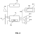
- the UI 40 can be a dedicated device (e.g. a panel) providing the control data for the luminaires 20-1 to 20-N via the Ethernet connection 120.
- a dedicated device e.g. a panel
- the IP-controlled luminaires 20-1 to 20-N offer many advantages, as described above. However, the cost is high due to the need for Ethernet in each luminaire. In addition, when the luminaires 20-1 to 20-N are switched off, there is still some power consumption in the system since Ethernet is still active in each luminaire and since the PSU 102 in the PoE switch 10 is still on.
- a further disadvantage is the size of the driver 202 that has to be accommodated in the luminaires 20-1 to 20-N. For some luminaire types this size is no issue, but for some luminaire types, miniaturization is a value driver.
- US 2010/0171602 A1 discloses a management agent which has access to power output control circuitry of a digital electronic communication switch, a power meter, a load sharing means, and the ability to manage the power of switching circuits in the switch.
- the power meter enables the management agent to identify the power consumed by the switching circuits that are enabled and operational. This information, coupled with knowledge of the power allocated to each port via PoE, and policy information which specifies power allocation preferences is used in a two-pass power management method.
- US 2004/0105435 A1 discloses a communication port management apparatus.
- An SNMP program actuated on a computer successively inquires of network devices about their settings and statuses. Each of the network devices having received such an inquiry returns the status and setting of each port.
- the computer SNMP program
- the minimum amount of control that must be implemented is to be able to switch the dumb lamps on or off.
- the mains supply to the PoE switch can be switched, but this is not desired in a PoE lighting system. This has the effect of switching on/off all luminaires that are connected to that switch. This would however also break the data link of all devices connected to that switch. Therefore, it should be possible to switch individual luminaires and also connect devices to the switch that require a continuous data link. Furthermore, the switching process may be too slow. It could take more than 1min for lights to turn on after the mains is applied. The reason is that PoE authentication can take up to 2s, and is done port by port.
- the required link can be automatically formed between devices that are located on the same network switch (i.e. PoE switch). To achieve this, individual ports of the PoE switch are switched on and off by making use of SNMP.
- Fig. 3 shows a schematic block diagram of a power distribution control system according to a first embodiment with an exemplary number of four dumb lamps 60-1 to 60-4 without any significant processing and/or communication capability.
- the dumb lamps 60-1 to 60-4 are powered by PoE but do not possess any significant processing/communication capability except what is necessary to transfer power via PoE (this may be embedded in the PoE power distribution integrated circuit). When voltage is applied through PoE, they will turn on and when there is no power, they will obviously be off.
- the dumb lamps 60-1 to 60-4 or other kind of dumb loads are connected to a PoE switch 50.
- one or more controllers (i.e. on/off switches) 56 are provided with IP node functionality and SNMP capability.
- the supply of data and power to the ports 55-1 to 55-4 is achieved via a layer-2 network switch 54 based on respective MAC addresses.
- An uplink port (UL) 58 is provided for IP uplink traffic via a connection 130 to the Internet.
- the power distribution control system automatically works such that toggling a light switch 70 (i.e. a lighting control switch or lighting controller) connected to an Ethernet port P5 of the PoE switch 50 disables supply of power from a main power supply unit (PSU) 52 via PoE connections P to those ports (P1 to P4) 55-1 to 55-4 of the PoE switch 50 that do not contain an IP node. Thus, to those ports to which the dumb lamps 60-1 to 60-4 are connected.
- PSU main power supply unit
- the light switch 70 is powered via a PoE connection P and sends commands via an Ethernet data connection D to the PoE switch 50 to switch specific ports on and off.
- the light switch 70 may be implemented as a simple wall switch or a sensor connected to the same Ethernet network as the PoE switch 50 and can switch on and off specific ones or all of the dumb lamps 60-1 to 60-4 when presence of people is detected. This can be done by sending commands to the PoE switch 50 to switch on and off specific ones or all of the PoE ports 55-1 to 55-4.
- the light switch 70 may be implemented as a UI adapted to manually switch off specific ones or all of the PoE ports 55-1 to 55-4.
- the light switch 70 may be implemented as a building management system which gets input from sensors and other devices and has a program running that controls the lighting (e.g. depending on the time of the day, day of the week).
- the light switch 70 is capable of enabling/disabling PoE power supply individually per PoE port and querying MAC addresses lookup tables via SNMP. More specifically, the light switch 70 may discover what PoE switch it is connected to by employing an IP network scan and probing for its own MAC address in the cache tables of SNMP compatible network switches. Additionally, a way in which the light switch 70 may discover which PoE ports of the switch should be turned on/off when the light switch 70 is toggled is by checking which MAC cache tables of a certain PoE port are empty while a PoE device is present on the other side. An alternative is to simply look for PoE ports that do not have link-up, or have empty MAC cache tables.
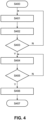
- Fig. 4 shows a flow diagram of an automatic system configuration procedure according to a second embodiment where a lighting control device (e.g. the light switch 70 of Fig. 3 ) controls PoE ports of a PoE switch with commands according to the SNMP protocol.
- a lighting control device e.g. the light switch 70 of Fig. 3
- step S400 the IP node of the lighting control device must find out the IP address of the PoE switch it is connected to.
- this node will receive an IP address and network mask from a Dynamic Host Configuration Protocol (DHCP) server and can then scan all the IP addresses of its subnet to find hosts that offer SNMP.
- DHCP Dynamic Host Configuration Protocol
- DHCP is a standardized networking protocol used on IP networks that dynamically configures IP addresses and other information that is needed for Internet communication. DHCP allows computers and other devices to receive an IP address automatically from a central DHCP server, reducing the need for a network administrator or a user from having to configure these settings manually.
- step S404 the lighting controller checks if port(s) with no associated MAC address have been found. If not, the procedure jumps back to step S404 and repeats the monitoring process. As an alternative, the procedure may be stopped here. If the lighting controller determines in step S405 that at least one port with no associated MAC address has been found, the procedure proceeds to step S406 and the detected ports are memorized (e.g. stored in a look-up table) for subsequent switching operation and the power distribution control system is now configured for proper operation. In step S407, the procedure ends.
- the proposed control system can be used to implement minimal control features into a PoE lighting network. It will provide simple on/off functionality and automatic commissioning based on the physical network infrastructure.
- a single unit or device may fulfill the functions of several items recited in the claims.
- the mere fact that certain measures are recited in mutually different dependent claims does not indicate that a combination of these measures cannot be used to advantage.
- the described operations like the one indicated in Fig. 4 can be implemented as program code means of a computer program and/or as dedicated hardware.
- the computer program may be stored and/or distributed on a suitable medium, such as an optical storage medium or a solid-state medium, supplied together with or as part of other hardware, but may also be distributed in other forms, such as via the Internet or other wired or wireless telecommunication systems.
Landscapes
- Engineering & Computer Science (AREA)
- Computer Networks & Wireless Communication (AREA)
- Signal Processing (AREA)
- Circuit Arrangement For Electric Light Sources In General (AREA)
- Small-Scale Networks (AREA)
- Selective Calling Equipment (AREA)
Claims (9)
- Dispositif de commande (70) permettant de commander la distribution de puissance à des éléments de charge (60-1 à 60-4) connectés à un commutateur réseau à puissance par Ethernet, PoE, par l'intermédiaire de connexions réseau LAN, dans lequel ledit dispositif de commande (70) est conçu pour découvrir un commutateur réseau PoE (50) auquel il est connecté en faisant appel à un balayage de réseau et en sondant sa propre adresse réseau dans des tables de cache d'un commutateur réseau compatible avec un protocole de gestion de réseau ; dans lequel ledit dispositif de commande (70) stocke dans une table de consultation des ports LAN (55-1 à 55-4) du commutateur réseau PoE (50), et lorsque les dispositifs de charge et le dispositif de commande sont connectés audit commutateur réseau PoE ils sont automatiquement appariés l'un à l'autre,
dans lequel ledit dispositif de commande (70) est conçu pour émettre des instructions de commande d'un protocole de gestion de réseau audit commutateur réseau PoE (50) détecté afin d'activer ou de désactiver les ports LAN (55-1 à 55-4) dudit commutateur réseau PoE (50), par le biais desquels ladite puissance est alimentée à des respectifs parmi lesdits éléments de charge (60-1 à 60-4), dans lequel ledit protocole de gestion de réseau est le protocole de gestion de réseau simple, SNMP, dans lequel on utilise la puissance par Ethernet, PoE, pour ladite distribution de puissance. - Dispositif de commande selon la revendication 1, dans lequel lesdits éléments de charge sont des luminaires (60-1 à 60-4) qui sont conçus pour utiliser leur connexion LAN respective pour un transfert de puissance uniquement.
- Dispositif de commande selon la revendication 1, dans lequel ledit dispositif de commande (70) est conçu pour découvrir lesdits ports LAN (55-1 à 55-4) en vérifiant quelles tables de cache d'adresses de couche 2 de ports LAN disponibles d'un commutateur réseau (50) découvert sont vides ou n'ont pas de liaison ascendante.
- Dispositif de commande selon la revendication 1, dans lequel ledit dispositif de commande (70) comprend un commutateur mural ou un capteur permettant de détecter la présence de personnes et initiant une opération de commutation de puissance en réponse à un résultat de détection, ou une interface utilisateur permettant d'initier manuellement ladite opération de commutation de puissance, ou un système de gestion de bâtiment permettant de commander l'éclairage en fonction d'entrées de capteur.
- Dispositif de commande selon la revendication 1, dans lequel ledit commutateur réseau (50) est un dispositif d'alimentation intermédiaire.
- Système permettant de commander une distribution de puissance à des éléments de charge (60-1 à 60-4) par l'intermédiaire de connexions de réseau local, LAN, ledit système comprenant au moins un dispositif de commande selon l'une quelconque des revendications 1 à 4 et un commutateur réseau (50).
- Système selon la revendication 6, dans lequel ledit commutateur réseau (50) est conçu pour désactiver une unité d'alimentation en puissance principale (52) si tous ses ports LAN sont désactivés.
- Procédé destiné à un dispositif de commande (70) permettant de commander une distribution de puissance à des éléments de charge (60-1 à 60-4) connectés à un commutateur réseau à puissance par Ethernet, PoE, par l'intermédiaire de connexions de réseau local, LAN, ledit procédé comprenant :- la découverte d'un commutateur réseau à puissance par Ethernet, PoE (50) en faisant appel à un balayage de réseau et à un sondage de sa propre adresse réseau dans des tables de cache d'un commutateur réseau compatible avec un protocole de gestion de réseau,- le stockage dans une table de consultation de ports LAN (55-1 à 55-4) du commutateur réseau PoE (50), dans lequel lorsque les dispositifs de charge et le dispositif de commande sont connectés audit commutateur réseau PoE ils sont automatiquement appariés l'un à l'autre,- l'émission d'instructions de commande d'un protocole de gestion de réseau audit commutateur réseau PoE (50) afin d'activer ou de désactiver des ports LAN (55-1 à 55-4) dudit commutateur réseau PoE (50) découvert, par le biais desquels ladite puissance est alimentée à des respectifs parmi lesdits éléments de charge (60-1 à 60-4), dans lequel ledit protocole de gestion de réseau est le protocole de gestion de réseau simple, SNMP.
- Produit programme informatique comprenant un moyen de code permettant de produire les étapes de la revendication 8 lorsqu'il est exécuté sur un dispositif informatique.
Priority Applications (1)
| Application Number | Priority Date | Filing Date | Title |
|---|---|---|---|
| EP15701701.3A EP3097656B1 (fr) | 2014-01-22 | 2015-01-14 | Système pour commander la distribution d'énergie pour charger des éléments. |
Applications Claiming Priority (3)
| Application Number | Priority Date | Filing Date | Title |
|---|---|---|---|
| EP14152142 | 2014-01-22 | ||
| EP15701701.3A EP3097656B1 (fr) | 2014-01-22 | 2015-01-14 | Système pour commander la distribution d'énergie pour charger des éléments. |
| PCT/EP2015/050539 WO2015110324A1 (fr) | 2014-01-22 | 2015-01-14 | Système de distribution de puissance de faible complexité et à faible consommation d'énergie |
Publications (2)
| Publication Number | Publication Date |
|---|---|
| EP3097656A1 EP3097656A1 (fr) | 2016-11-30 |
| EP3097656B1 true EP3097656B1 (fr) | 2025-03-12 |
Family
ID=50002523
Family Applications (1)
| Application Number | Title | Priority Date | Filing Date |
|---|---|---|---|
| EP15701701.3A Active EP3097656B1 (fr) | 2014-01-22 | 2015-01-14 | Système pour commander la distribution d'énergie pour charger des éléments. |
Country Status (5)
| Country | Link |
|---|---|
| US (1) | US10069636B2 (fr) |
| EP (1) | EP3097656B1 (fr) |
| JP (1) | JP6588446B2 (fr) |
| CN (1) | CN106165343B (fr) |
| WO (1) | WO2015110324A1 (fr) |
Families Citing this family (16)
| Publication number | Priority date | Publication date | Assignee | Title |
|---|---|---|---|---|
| WO2017036746A1 (fr) * | 2015-08-31 | 2017-03-09 | Philips Lighting Holding B.V. | Système, dispositif et procédé permettant de commander des applications de réseau |
| US9521009B1 (en) * | 2016-01-20 | 2016-12-13 | Creston Electronics, Inc. | Auto-configuration and automation of a building management system |
| US11221111B2 (en) | 2016-02-15 | 2022-01-11 | Molex, Llc | Luminaire |
| US11909540B2 (en) * | 2016-03-03 | 2024-02-20 | Molex, Llc | System and method for power over ethernet control |
| EP3427438B1 (fr) | 2016-03-08 | 2019-07-03 | Signify Holding B.V. | Dispositif alimenté en courant continu et dispositif électrique pour la surveillance de données opérationnelles non autorisées |
| CN111902834A (zh) * | 2018-01-25 | 2020-11-06 | 比特股份有限公司 | 处理数字化系统和方法 |
| JP7077149B2 (ja) * | 2018-06-05 | 2022-05-30 | 古野電気株式会社 | ネットワーク制御システム、ネットワーク管理装置、及びネットワーク管理方法 |
| CA3155694A1 (fr) * | 2019-09-24 | 2021-04-01 | Genetec Inc. | Dispositif intermediaire pour configuration en guirlande et en arbre dans une connexion hybride de donnees/puissance |
| JP7419928B2 (ja) * | 2020-03-27 | 2024-01-23 | 東芝ライテック株式会社 | 制御装置 |
| US11770155B2 (en) | 2020-05-19 | 2023-09-26 | Genetec Inc. | Power distribution and data routing in a network of devices interconnected by hybrid data/power links |
| US11825574B2 (en) | 2020-12-29 | 2023-11-21 | Crestron Electronics, Inc. | System and method of commissioning a building control system |
| JP7573182B2 (ja) * | 2021-02-01 | 2024-10-25 | パナソニックIpマネジメント株式会社 | 機器制御システム |
| JP7649961B2 (ja) * | 2021-02-01 | 2025-03-24 | パナソニックIpマネジメント株式会社 | 機器制御システム |
| US11372463B1 (en) | 2021-02-19 | 2022-06-28 | Hewlett Packard Enterprise Development Lp | Power down of power over ethernet interfaces |
| US11669137B2 (en) | 2021-07-29 | 2023-06-06 | Hewlett Packard Enterprise Development Lp | Power down of power over Ethernet interfaces |
| US12506660B2 (en) * | 2022-05-24 | 2025-12-23 | Electronic Warfare Associates, Inc. | Node for providing power and communication functionality to field deployed systems |
Family Cites Families (17)
| Publication number | Priority date | Publication date | Assignee | Title |
|---|---|---|---|---|
| AU2002354123A1 (en) | 2002-11-28 | 2004-06-18 | Allied Telesis K.K. | Communication port control device and method thereof |
| US20080197790A1 (en) | 2002-12-11 | 2008-08-21 | Mangiaracina Anthony A | Lighting utilizing power over the ethernet |
| US20070075586A1 (en) * | 2005-10-05 | 2007-04-05 | Bogue Edward M | Ethernet powered device with an internaly controlled auxiliary power ouput |
| US8610305B2 (en) * | 2006-09-18 | 2013-12-17 | Hinbit Development Ltd. | Retrofitting power distribution device and uses thereof |
| WO2008073834A2 (fr) | 2006-12-08 | 2008-06-19 | Liebert Corporation | Dispositifs adressables par ip à configuration automatique utilisant deux ports ip à protocole ethernet |
| US7587289B1 (en) * | 2007-02-13 | 2009-09-08 | American Megatrends, Inc. | Data cable powered sensor fixture |
| JP5298689B2 (ja) * | 2008-07-30 | 2013-09-25 | 日本電気株式会社 | 給電システム、サーバ、給電方法、プログラム、及び記憶媒体 |
| US8164281B2 (en) * | 2008-08-01 | 2012-04-24 | Thomas Warton | Luminaire system and method |
| US8205102B2 (en) * | 2009-01-05 | 2012-06-19 | Hewlett-Packard Development Company, L.P. | Intelligent power management of an intermediate network device switching circuitry and PoE delivery |
| US9088434B2 (en) | 2009-02-06 | 2015-07-21 | Broadcom Corporation | System and method for power over ethernet power mode policy and network management |
| US8935543B2 (en) | 2010-04-02 | 2015-01-13 | Andrew Llc | Method and apparatus for distributing power over communication cabling |
| JP6058538B2 (ja) * | 2010-08-30 | 2017-01-11 | フィリップス ライティング ホールディング ビー ヴィ | Power−over−Ethernet装置の管理 |
| US8954763B2 (en) * | 2011-01-27 | 2015-02-10 | Commscope, Inc. Of North Carolina | Automated infrastructure management systems and methods for enabling real time energy management |
| US20120271477A1 (en) | 2011-04-25 | 2012-10-25 | Wizlan Ltd. | System And Method For Illumination Using Power Over Ethernet |
| JP6054125B2 (ja) * | 2011-10-04 | 2016-12-27 | 株式会社ユースフルパースン | Led照明装置の照明制御システム |
| RU2660454C2 (ru) * | 2012-08-06 | 2018-07-06 | Филипс Лайтинг Холдинг Б.В. | Стандартный ввод в эксплуатацию системы управления освещением |
| US20140180723A1 (en) * | 2012-12-21 | 2014-06-26 | The Travelers Indemnity Company | Systems and methods for surface segment data |
-
2015
- 2015-01-14 US US15/112,424 patent/US10069636B2/en active Active
- 2015-01-14 JP JP2016547136A patent/JP6588446B2/ja not_active Expired - Fee Related
- 2015-01-14 CN CN201580005514.9A patent/CN106165343B/zh active Active
- 2015-01-14 EP EP15701701.3A patent/EP3097656B1/fr active Active
- 2015-01-14 WO PCT/EP2015/050539 patent/WO2015110324A1/fr not_active Ceased
Also Published As
| Publication number | Publication date |
|---|---|
| US10069636B2 (en) | 2018-09-04 |
| CN106165343B (zh) | 2019-11-05 |
| EP3097656A1 (fr) | 2016-11-30 |
| JP6588446B2 (ja) | 2019-10-09 |
| JP2017508244A (ja) | 2017-03-23 |
| WO2015110324A1 (fr) | 2015-07-30 |
| US20160337137A1 (en) | 2016-11-17 |
| CN106165343A (zh) | 2016-11-23 |
Similar Documents
| Publication | Publication Date | Title |
|---|---|---|
| US10069636B2 (en) | Power distribution system with low complexity and low power consumption | |
| US10845855B2 (en) | Management of power-over-ethernet installation | |
| US10743390B2 (en) | Out-of-the-box commissioning of a control system | |
| US10405405B2 (en) | Apparatus, method and system for controlling a load device via a power line by using a power negotiation protocol | |
| JP6058864B2 (ja) | 配電システム | |
| CN107430421B (zh) | 以太网供电网络系统中的受电设备及其方法 | |
| JP2016195119A (ja) | 電気消費機器に対してデータ接続を介して電力供給する装置 | |
| CN103404165A (zh) | 自动化基础设施管理系统以及用于实现实时能量管理的方法 | |
| US20260059636A1 (en) | Resistor Mapping for Device Profiles | |
| WO2024256217A1 (fr) | Dispositif d'éclairage alimenté en courant continu et son procédé de commande de fonctionnement |
Legal Events
| Date | Code | Title | Description |
|---|---|---|---|
| PUAI | Public reference made under article 153(3) epc to a published international application that has entered the european phase |
Free format text: ORIGINAL CODE: 0009012 |
|
| 17P | Request for examination filed |
Effective date: 20160822 |
|
| AK | Designated contracting states |
Kind code of ref document: A1 Designated state(s): AL AT BE BG CH CY CZ DE DK EE ES FI FR GB GR HR HU IE IS IT LI LT LU LV MC MK MT NL NO PL PT RO RS SE SI SK SM TR |
|
| AX | Request for extension of the european patent |
Extension state: BA ME |
|
| DAX | Request for extension of the european patent (deleted) | ||
| RIN1 | Information on inventor provided before grant (corrected) |
Inventor name: VERBRUGH, STEFAN MARCUS Inventor name: THEUNISSEN, BOB BERNARDUS ANTHONIUS Inventor name: VAN DER ZANDEN, HENRICUS THEODORUS Inventor name: YSEBOODT, LENNART Inventor name: WENDT, MATTHIAS |
|
| STAA | Information on the status of an ep patent application or granted ep patent |
Free format text: STATUS: EXAMINATION IS IN PROGRESS |
|
| 17Q | First examination report despatched |
Effective date: 20180327 |
|
| RAP1 | Party data changed (applicant data changed or rights of an application transferred) |
Owner name: PHILIPS LIGHTING HOLDING B.V. |
|
| RAP1 | Party data changed (applicant data changed or rights of an application transferred) |
Owner name: SIGNIFY HOLDING B.V. |
|
| REG | Reference to a national code |
Ref country code: DE Ref legal event code: R079 Free format text: PREVIOUS MAIN CLASS: H04L0012100000 Ipc: H04L0012400000 Ref country code: DE Ref legal event code: R079 Ref document number: 602015091185 Country of ref document: DE Free format text: PREVIOUS MAIN CLASS: H04L0012100000 Ipc: H04L0012400000 |
|
| GRAP | Despatch of communication of intention to grant a patent |
Free format text: ORIGINAL CODE: EPIDOSNIGR1 |
|
| STAA | Information on the status of an ep patent application or granted ep patent |
Free format text: STATUS: GRANT OF PATENT IS INTENDED |
|
| RIC1 | Information provided on ipc code assigned before grant |
Ipc: H04L 12/46 20060101ALI20240913BHEP Ipc: H04L 12/40 20060101AFI20240913BHEP |
|
| INTG | Intention to grant announced |
Effective date: 20240925 |
|
| P01 | Opt-out of the competence of the unified patent court (upc) registered |
Free format text: CASE NUMBER: APP_61232/2024 Effective date: 20241114 |
|
| GRAS | Grant fee paid |
Free format text: ORIGINAL CODE: EPIDOSNIGR3 |
|
| GRAA | (expected) grant |
Free format text: ORIGINAL CODE: 0009210 |
|
| STAA | Information on the status of an ep patent application or granted ep patent |
Free format text: STATUS: THE PATENT HAS BEEN GRANTED |
|
| AK | Designated contracting states |
Kind code of ref document: B1 Designated state(s): AL AT BE BG CH CY CZ DE DK EE ES FI FR GB GR HR HU IE IS IT LI LT LU LV MC MK MT NL NO PL PT RO RS SE SI SK SM TR |
|
| REG | Reference to a national code |
Ref country code: GB Ref legal event code: FG4D |
|
| REG | Reference to a national code |
Ref country code: CH Ref legal event code: EP |
|
| REG | Reference to a national code |
Ref country code: DE Ref legal event code: R096 Ref document number: 602015091185 Country of ref document: DE |
|
| REG | Reference to a national code |
Ref country code: IE Ref legal event code: FG4D |
|
| PG25 | Lapsed in a contracting state [announced via postgrant information from national office to epo] |
Ref country code: RS Free format text: LAPSE BECAUSE OF FAILURE TO SUBMIT A TRANSLATION OF THE DESCRIPTION OR TO PAY THE FEE WITHIN THE PRESCRIBED TIME-LIMIT Effective date: 20250612 |
|
| PG25 | Lapsed in a contracting state [announced via postgrant information from national office to epo] |
Ref country code: FI Free format text: LAPSE BECAUSE OF FAILURE TO SUBMIT A TRANSLATION OF THE DESCRIPTION OR TO PAY THE FEE WITHIN THE PRESCRIBED TIME-LIMIT Effective date: 20250312 |
|
| PG25 | Lapsed in a contracting state [announced via postgrant information from national office to epo] |
Ref country code: ES Free format text: LAPSE BECAUSE OF FAILURE TO SUBMIT A TRANSLATION OF THE DESCRIPTION OR TO PAY THE FEE WITHIN THE PRESCRIBED TIME-LIMIT Effective date: 20250312 |
|
| REG | Reference to a national code |
Ref country code: LT Ref legal event code: MG9D |
|
| PG25 | Lapsed in a contracting state [announced via postgrant information from national office to epo] |
Ref country code: NO Free format text: LAPSE BECAUSE OF FAILURE TO SUBMIT A TRANSLATION OF THE DESCRIPTION OR TO PAY THE FEE WITHIN THE PRESCRIBED TIME-LIMIT Effective date: 20250612 |
|
| PG25 | Lapsed in a contracting state [announced via postgrant information from national office to epo] |
Ref country code: HR Free format text: LAPSE BECAUSE OF FAILURE TO SUBMIT A TRANSLATION OF THE DESCRIPTION OR TO PAY THE FEE WITHIN THE PRESCRIBED TIME-LIMIT Effective date: 20250312 |
|
| REG | Reference to a national code |
Ref country code: NL Ref legal event code: MP Effective date: 20250312 |
|
| PG25 | Lapsed in a contracting state [announced via postgrant information from national office to epo] |
Ref country code: LV Free format text: LAPSE BECAUSE OF FAILURE TO SUBMIT A TRANSLATION OF THE DESCRIPTION OR TO PAY THE FEE WITHIN THE PRESCRIBED TIME-LIMIT Effective date: 20250312 |
|
| PG25 | Lapsed in a contracting state [announced via postgrant information from national office to epo] |
Ref country code: GR Free format text: LAPSE BECAUSE OF FAILURE TO SUBMIT A TRANSLATION OF THE DESCRIPTION OR TO PAY THE FEE WITHIN THE PRESCRIBED TIME-LIMIT Effective date: 20250613 Ref country code: BG Free format text: LAPSE BECAUSE OF FAILURE TO SUBMIT A TRANSLATION OF THE DESCRIPTION OR TO PAY THE FEE WITHIN THE PRESCRIBED TIME-LIMIT Effective date: 20250312 |
|
| REG | Reference to a national code |
Ref country code: AT Ref legal event code: MK05 Ref document number: 1775968 Country of ref document: AT Kind code of ref document: T Effective date: 20250312 |
|
| PG25 | Lapsed in a contracting state [announced via postgrant information from national office to epo] |
Ref country code: NL Free format text: LAPSE BECAUSE OF FAILURE TO SUBMIT A TRANSLATION OF THE DESCRIPTION OR TO PAY THE FEE WITHIN THE PRESCRIBED TIME-LIMIT Effective date: 20250312 |
|
| PG25 | Lapsed in a contracting state [announced via postgrant information from national office to epo] |
Ref country code: SE Free format text: LAPSE BECAUSE OF FAILURE TO SUBMIT A TRANSLATION OF THE DESCRIPTION OR TO PAY THE FEE WITHIN THE PRESCRIBED TIME-LIMIT Effective date: 20250312 |
|
| PG25 | Lapsed in a contracting state [announced via postgrant information from national office to epo] |
Ref country code: SM Free format text: LAPSE BECAUSE OF FAILURE TO SUBMIT A TRANSLATION OF THE DESCRIPTION OR TO PAY THE FEE WITHIN THE PRESCRIBED TIME-LIMIT Effective date: 20250312 |
|
| PG25 | Lapsed in a contracting state [announced via postgrant information from national office to epo] |
Ref country code: PT Free format text: LAPSE BECAUSE OF FAILURE TO SUBMIT A TRANSLATION OF THE DESCRIPTION OR TO PAY THE FEE WITHIN THE PRESCRIBED TIME-LIMIT Effective date: 20250714 |
|
| PG25 | Lapsed in a contracting state [announced via postgrant information from national office to epo] |
Ref country code: IT Free format text: LAPSE BECAUSE OF FAILURE TO SUBMIT A TRANSLATION OF THE DESCRIPTION OR TO PAY THE FEE WITHIN THE PRESCRIBED TIME-LIMIT Effective date: 20250312 Ref country code: PL Free format text: LAPSE BECAUSE OF FAILURE TO SUBMIT A TRANSLATION OF THE DESCRIPTION OR TO PAY THE FEE WITHIN THE PRESCRIBED TIME-LIMIT Effective date: 20250312 |
|
| PG25 | Lapsed in a contracting state [announced via postgrant information from national office to epo] |
Ref country code: AT Free format text: LAPSE BECAUSE OF FAILURE TO SUBMIT A TRANSLATION OF THE DESCRIPTION OR TO PAY THE FEE WITHIN THE PRESCRIBED TIME-LIMIT Effective date: 20250312 |
|
| PG25 | Lapsed in a contracting state [announced via postgrant information from national office to epo] |
Ref country code: EE Free format text: LAPSE BECAUSE OF FAILURE TO SUBMIT A TRANSLATION OF THE DESCRIPTION OR TO PAY THE FEE WITHIN THE PRESCRIBED TIME-LIMIT Effective date: 20250312 Ref country code: CZ Free format text: LAPSE BECAUSE OF FAILURE TO SUBMIT A TRANSLATION OF THE DESCRIPTION OR TO PAY THE FEE WITHIN THE PRESCRIBED TIME-LIMIT Effective date: 20250312 |
|
| PG25 | Lapsed in a contracting state [announced via postgrant information from national office to epo] |
Ref country code: RO Free format text: LAPSE BECAUSE OF FAILURE TO SUBMIT A TRANSLATION OF THE DESCRIPTION OR TO PAY THE FEE WITHIN THE PRESCRIBED TIME-LIMIT Effective date: 20250312 |
|
| PG25 | Lapsed in a contracting state [announced via postgrant information from national office to epo] |
Ref country code: SK Free format text: LAPSE BECAUSE OF FAILURE TO SUBMIT A TRANSLATION OF THE DESCRIPTION OR TO PAY THE FEE WITHIN THE PRESCRIBED TIME-LIMIT Effective date: 20250312 |
|
| PG25 | Lapsed in a contracting state [announced via postgrant information from national office to epo] |
Ref country code: IS Free format text: LAPSE BECAUSE OF FAILURE TO SUBMIT A TRANSLATION OF THE DESCRIPTION OR TO PAY THE FEE WITHIN THE PRESCRIBED TIME-LIMIT Effective date: 20250712 |
|
| REG | Reference to a national code |
Ref country code: DE Ref legal event code: R097 Ref document number: 602015091185 Country of ref document: DE |
|
| PG25 | Lapsed in a contracting state [announced via postgrant information from national office to epo] |
Ref country code: DK Free format text: LAPSE BECAUSE OF FAILURE TO SUBMIT A TRANSLATION OF THE DESCRIPTION OR TO PAY THE FEE WITHIN THE PRESCRIBED TIME-LIMIT Effective date: 20250312 |
|
| PLBE | No opposition filed within time limit |
Free format text: ORIGINAL CODE: 0009261 |
|
| STAA | Information on the status of an ep patent application or granted ep patent |
Free format text: STATUS: NO OPPOSITION FILED WITHIN TIME LIMIT |
|
| REG | Reference to a national code |
Ref country code: CH Ref legal event code: L10 Free format text: ST27 STATUS EVENT CODE: U-0-0-L10-L00 (AS PROVIDED BY THE NATIONAL OFFICE) Effective date: 20260121 |
|
| 26N | No opposition filed |
Effective date: 20251215 |
|
| PG25 | Lapsed in a contracting state [announced via postgrant information from national office to epo] |
Ref country code: LT Free format text: LAPSE BECAUSE OF FAILURE TO SUBMIT A TRANSLATION OF THE DESCRIPTION OR TO PAY THE FEE WITHIN THE PRESCRIBED TIME-LIMIT Effective date: 20250312 |