EP3097251B1 - Method for drilling a well in continuous circulation and device for intercepting and redistributing fluid used in this method - Google Patents
Method for drilling a well in continuous circulation and device for intercepting and redistributing fluid used in this method Download PDFInfo
- Publication number
- EP3097251B1 EP3097251B1 EP15704202.9A EP15704202A EP3097251B1 EP 3097251 B1 EP3097251 B1 EP 3097251B1 EP 15704202 A EP15704202 A EP 15704202A EP 3097251 B1 EP3097251 B1 EP 3097251B1
- Authority
- EP
- European Patent Office
- Prior art keywords
- flow
- drilling
- direct
- valve
- auxiliary
- Prior art date
- Legal status (The legal status is an assumption and is not a legal conclusion. Google has not performed a legal analysis and makes no representation as to the accuracy of the status listed.)
- Active
Links
- 238000005553 drilling Methods 0.000 title claims description 52
- 239000012530 fluid Substances 0.000 title claims description 46
- 238000000034 method Methods 0.000 title claims description 15
- 238000004891 communication Methods 0.000 claims description 13
- 238000003780 insertion Methods 0.000 claims 1
- 230000037431 insertion Effects 0.000 claims 1
- 238000010586 diagram Methods 0.000 description 2
- 230000003628 erosive effect Effects 0.000 description 2
- 238000012423 maintenance Methods 0.000 description 1
- 239000007787 solid Substances 0.000 description 1
- 230000002459 sustained effect Effects 0.000 description 1
- 230000001052 transient effect Effects 0.000 description 1
- XLYOFNOQVPJJNP-UHFFFAOYSA-N water Substances O XLYOFNOQVPJJNP-UHFFFAOYSA-N 0.000 description 1
Images


Classifications
-
- E—FIXED CONSTRUCTIONS
- E21—EARTH OR ROCK DRILLING; MINING
- E21B—EARTH OR ROCK DRILLING; OBTAINING OIL, GAS, WATER, SOLUBLE OR MELTABLE MATERIALS OR A SLURRY OF MINERALS FROM WELLS
- E21B21/00—Methods or apparatus for flushing boreholes, e.g. by use of exhaust air from motor
- E21B21/10—Valve arrangements in drilling-fluid circulation systems
- E21B21/106—Valve arrangements outside the borehole, e.g. kelly valves
-
- E—FIXED CONSTRUCTIONS
- E21—EARTH OR ROCK DRILLING; MINING
- E21B—EARTH OR ROCK DRILLING; OBTAINING OIL, GAS, WATER, SOLUBLE OR MELTABLE MATERIALS OR A SLURRY OF MINERALS FROM WELLS
- E21B21/00—Methods or apparatus for flushing boreholes, e.g. by use of exhaust air from motor
- E21B21/10—Valve arrangements in drilling-fluid circulation systems
Definitions
- the present invention relates to a method for drilling a well in continuous circulation.
- the invention also relates to the device for intercepting and redistributing fluid used in this method.
- the field of the invention is the drilling of a well in continuous circulation.
- the aim is to maintain a constant flow rate of the drilling fluid circulated inside the well, also during extension of the drill rod, in particular implemented by adding one or more preassembled elements to the string of drill rods.
- auxiliary chambers for intercepting and redistributing the drilling fluid, comprising a main chamber for entry of this fluid suitable to redistribute, between two separate non-communicating auxiliary chambers, the same intercepted fluid ( WO2008/095650 ). More specifically, one of the aforesaid auxiliary chambers operates exclusively during the well drilling step, while the remaining auxiliary chamber is used only during extension of the drill rod or of the drill string.
- the prior art described above mainly has the drawback of allowing the whole drilling fluid flow rate (therefore also high flow rates, for example over 3000 l/min, required for large diameter bores or when bottom hole equipment is present) to pass through only one of the two aforesaid auxiliary chambers. This significantly increases wear on the sections for changing the direction of flow inside the device, making it necessary to carry out maintenance operations that compromise the continuity of the overall drilling procedure. Similar drawbacks occur with the use of high density drilling fluids, which are rich in solids and therefore more erosive.
- the main object of the present invention is to provide a device for intercepting and redistributing fluid and related method for continuous circulation drilling, in which the aforesaid problems not encountered.
- an object of the invention is to provide a device of the aforesaid type, which allows wells to be drilled also at high flow rates and/or with highly erosive fluids, while drastically reducing load losses and resulting localized wear.
- the device and the method of the invention offer the advantage of significantly reducing localized wear on the system for intercepting and redistributing the drilling fluid, through exploitation of auxiliary chambers that are placed in fluid communication with one another and thereby allow even high flow rates, required for wells of larger dimensions and/or wells that use bottom hole equipment, to be sustained.
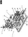
- the device of the invention for intercepting and redistributing drilling fluid in drilling rigs is indicated as a whole with 1 in Fig. 1 .
- This device comprises an inlet 2 for the direct flow F1 of the drilling fluid, an outlet 3 for the flow F2 of the fluid coming from the string of drill rods and an outlet 4 of the radial flow F3 of fluid from the same drill string, during the step to add an extension section to the drill string.
- the drilling fluid circulating in the device 1 can be mud, water or the like, which is circulated in the device of Figs. 1 and 2 passing through a main chamber 5, a first auxiliary chamber 6 and a second auxiliary chamber 7, all in fluid communication with one another.
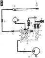
- the flow F1 entering the main chamber 5 is transferred to the first auxiliary chamber 6 passing through a flow control valve 8 and a pressure relief valve 9.
- the same flow F1 coming from the main chamber 5 also enters the second auxiliary chamber 7 passing through the respective flow control valve 10 and is transferred, from this chamber 7 to the first auxiliary chamber 6, passing through the flow control valve 11, which is provided to place the aforesaid auxiliary chambers 6 and 7 in communication.
- the first auxiliary chamber 6 also has a pressure relief valve 12, while the second auxiliary chamber 7 has a flow control valve13, a pressure valve14 and a discharge valve 15.
- auxiliary chambers 6 and 7 are placed in communication with each other through the valve 11, which allows the drilling fluid to circulate from the second chamber 7 towards the first chamber 6, to then be sent from here to the drilling system.
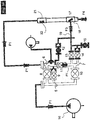
- the device 1 receives the flow F1 of drilling fluid supplied by a suitable piston pump 16, which first sends it to the main chamber 5 and, from here, both to the first auxiliary chamber 6 (passing through both its valves 8 and 9), and to the second auxiliary chamber 7, this time passing through the corresponding valve 10.
- the flow F1 supplied to the second auxiliary chamber 7 is also transferred inside the first auxiliary chamber 6, passing through the valve 11 that places the aforesaid auxiliary chambers in communication with each other during this drilling step. Therefore, a flow F2, the same as the flow F1 that exits from the first auxiliary chamber 6 of the device of the invention, is sent to the string of drill rods.
- the valve 12 of the chamber 6 and the valves 13, 14 of the chamber 7 are all closed.
- the drilling system is placed exclusively in the radial circulation mode shown in Fig. 7 , both by closing the valves 8, 9 and 11, which in this way isolate the first auxiliary chamber 6 from the flow of drilling fluid circulating between the chambers 5 and 7, and by closing the valve 18 to the direct circulation.
- the flow of fluid supplied by the pump 16 is sent first to the main chamber 5, then to the second auxiliary chamber 7 (passing through the respective valve 10), then to the drill string 17 through the valves 13 and 14 (18 is in closed position), generating a radial drilling flow F3.
- the valve 12 of the first auxiliary chamber 6 is maintained open. In these conditions the flow F5 of fluid present in the line 20 is discharged towards the outside and, as this line is in depressurized state, it is in turn hermetically closed by the valve 18 placed inside the drill string 17 ( Fig. 7 ). At this point it is possible to add, to the line 20 which has thus been emptied of circulating fluid, a supplementary rod 21 for extension of the drill string 17, also equipped with its own radial valve 22 ( Fig. 8 ).
- the extension rod 21 and the respective supply line 20 are filled with drilling fluid supplied through a filling valve 24 of the first auxiliary chamber 6, by means of a flow F6 generated by a respective pump 23 ( Fig. 8 ). From this moment the valve 24 is closed and the valve 9 is opened, thereby pressurizing the first auxiliary chamber 6, the rod 21 and the respective line 20 of the direct drilling flow ( Fig. 9 ).
- valves 13 and 14 that control the radial flow exiting from the second auxiliary chamber 7 ( Fig. 11 ), thereby restoring the direct circulation shown in Fig. 4 .
- valve 15 by opening the valve 15 the pressure trapped in the radial channel 19 of this auxiliary chamber 7 is discharged, thereby allowing the aforesaid channel 19 to be disconnected from the rod 17 to restore the direct flow drilling mode.
Landscapes
- Engineering & Computer Science (AREA)
- Life Sciences & Earth Sciences (AREA)
- Geology (AREA)
- Mining & Mineral Resources (AREA)
- Mechanical Engineering (AREA)
- Physics & Mathematics (AREA)
- Environmental & Geological Engineering (AREA)
- Fluid Mechanics (AREA)
- General Life Sciences & Earth Sciences (AREA)
- Geochemistry & Mineralogy (AREA)
- Earth Drilling (AREA)
- Physical Or Chemical Processes And Apparatus (AREA)
Description
- The present invention relates to a method for drilling a well in continuous circulation. The invention also relates to the device for intercepting and redistributing fluid used in this method.
- The field of the invention is the drilling of a well in continuous circulation. In this type of operation, the aim is to maintain a constant flow rate of the drilling fluid circulated inside the well, also during extension of the drill rod, in particular implemented by adding one or more preassembled elements to the string of drill rods.
- For this purpose the use is known of devices for intercepting and redistributing the drilling fluid, comprising a main chamber for entry of this fluid suitable to redistribute, between two separate non-communicating auxiliary chambers, the same intercepted fluid (
WO2008/095650 ). More specifically, one of the aforesaid auxiliary chambers operates exclusively during the well drilling step, while the remaining auxiliary chamber is used only during extension of the drill rod or of the drill string. - The prior art described above mainly has the drawback of allowing the whole drilling fluid flow rate (therefore also high flow rates, for example over 3000 l/min, required for large diameter bores or when bottom hole equipment is present) to pass through only one of the two aforesaid auxiliary chambers. This significantly increases wear on the sections for changing the direction of flow inside the device, making it necessary to carry out maintenance operations that compromise the continuity of the overall drilling procedure. Similar drawbacks occur with the use of high density drilling fluids, which are rich in solids and therefore more erosive.
- The main object of the present invention is to provide a device for intercepting and redistributing fluid and related method for continuous circulation drilling, in which the aforesaid problems not encountered.
- In particular, an object of the invention is to provide a device of the aforesaid type, which allows wells to be drilled also at high flow rates and/or with highly erosive fluids, while drastically reducing load losses and resulting localized wear.
- These and other objects are achieved with the device and with the method of
claims 1 and 7 respectively. Preferred embodiments of the invention are set down in the remaining claims. - In relation to the prior art described above, the device and the method of the invention offer the advantage of significantly reducing localized wear on the system for intercepting and redistributing the drilling fluid, through exploitation of auxiliary chambers that are placed in fluid communication with one another and thereby allow even high flow rates, required for wells of larger dimensions and/or wells that use bottom hole equipment, to be sustained.
- These and other objects, advantages and characteristics will be apparent from the following description of a preferred embodiment of the method and the device of the invention illustrated, by way of non-limiting example, in the figures of the accompanying drawings.
- In these figures:
-
Fig. 1 shows a perspective view of an example of embodiment of the device of the invention; -
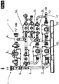
Fig. 2 shows the device ofFig. 1 in a side view; -
Fig. 3 shows a schematic diagram of the operation of the device ofFig. 1 ; -
Fig. 4 shows the device of the invention in drilling mode; -
Fig. 5 shows the device ofFig. 4 in pressurizing mode, preliminary to the combined direct and radial flow; -
Fig. 6 shows the device ofFig. 5 in combined direct and radial flow mode; -
Fig. 7 shows the device ofFig. 6 only in radial flow mode (i.e. in the absence of direct flow); -
Fig. 8 shows the device ofFig. 7 in which an extension section has been added to the drill string; -
Fig. 9 shows the device ofFig. 8 in the pressure equalization step, preliminary to combined direct and radial circulation; -
Fig. 10 shows the device ofFig. 9 in the combined circulation step; and -
Fig. 11 shows the device ofFig. 10 in the step to restore direct circulation of the drilling fluid. - The device of the invention for intercepting and redistributing drilling fluid in drilling rigs is indicated as a whole with 1 in
Fig. 1 . This device comprises aninlet 2 for the direct flow F1 of the drilling fluid, anoutlet 3 for the flow F2 of the fluid coming from the string of drill rods and anoutlet 4 of the radial flow F3 of fluid from the same drill string, during the step to add an extension section to the drill string. The drilling fluid circulating in the device 1 can be mud, water or the like, which is circulated in the device ofFigs. 1 and2 passing through amain chamber 5, a firstauxiliary chamber 6 and a secondauxiliary chamber 7, all in fluid communication with one another. - As can be seen from the diagram illustrated in
Fig. 3 , the flow F1 entering themain chamber 5 is transferred to the firstauxiliary chamber 6 passing through aflow control valve 8 and apressure relief valve 9. The same flow F1 coming from themain chamber 5 also enters the secondauxiliary chamber 7 passing through the respectiveflow control valve 10 and is transferred, from thischamber 7 to the firstauxiliary chamber 6, passing through theflow control valve 11, which is provided to place the aforesaidauxiliary chambers auxiliary chamber 6, which is sent to the string of drill rods 17 (Fig. 4 ). The firstauxiliary chamber 6 also has apressure relief valve 12, while the secondauxiliary chamber 7 has a flow control valve13, a pressure valve14 and adischarge valve 15. - Therefore the
auxiliary chambers valve 11, which allows the drilling fluid to circulate from thesecond chamber 7 towards thefirst chamber 6, to then be sent from here to the drilling system. - In direct circulation drilling mode shown in
Fig. 4 , the device 1 receives the flow F1 of drilling fluid supplied by asuitable piston pump 16, which first sends it to themain chamber 5 and, from here, both to the first auxiliary chamber 6 (passing through both itsvalves 8 and 9), and to the secondauxiliary chamber 7, this time passing through thecorresponding valve 10. The flow F1 supplied to the secondauxiliary chamber 7 is also transferred inside the firstauxiliary chamber 6, passing through thevalve 11 that places the aforesaid auxiliary chambers in communication with each other during this drilling step. Therefore, a flow F2, the same as the flow F1 that exits from the firstauxiliary chamber 6 of the device of the invention, is sent to the string of drill rods. In this drilling mode with direct circulation of the drilling fluid, thevalve 12 of thechamber 6 and thevalves chamber 7 are all closed. - In the operating mode shown in
Fig. 5 , corresponding to the transient state between the drilling modes and that of extension of the string ofdrill rods 17, thechambers Fig. 4 ). However, in this step thepressure valve 14 of thechamber 7 is no longer closed as before, but is open, so as to pressurize theradial channel 19, which places the secondauxiliary chamber 7 in fluid communication with the string ofdrill rods 17 through arespective valve 18. - In the subsequent step, shown in
Fig. 6 , in addition to thevalve 14 of thechamber 7, theflow control valve 13 is also open. In this way, a flow F3 is generated through thechannel 19 and enters the string ofrods 17 radially, passing through therespective valve 18 and producing, together with the flow F1, a flow of drilling fluid F4=F1+F3 corresponding to the placing the system in a state of combined circulation, respectively direct and radial. - From this moment, the drilling system is placed exclusively in the radial circulation mode shown in
Fig. 7 , both by closing thevalves auxiliary chamber 6 from the flow of drilling fluid circulating between thechambers valve 18 to the direct circulation. In these conditions the flow of fluid supplied by thepump 16 is sent first to themain chamber 5, then to the second auxiliary chamber 7 (passing through the respective valve 10), then to thedrill string 17 through thevalves 13 and 14 (18 is in closed position), generating a radial drilling flow F3. - In order to isolate the
direct circulation line 20 of the drilling fluid to the string ofrods 17 with respect to the radial flow F3, thevalve 12 of the firstauxiliary chamber 6 is maintained open. In these conditions the flow F5 of fluid present in theline 20 is discharged towards the outside and, as this line is in depressurized state, it is in turn hermetically closed by thevalve 18 placed inside the drill string 17 (Fig. 7 ). At this point it is possible to add, to theline 20 which has thus been emptied of circulating fluid, asupplementary rod 21 for extension of thedrill string 17, also equipped with its own radial valve 22 (Fig. 8 ). - Before returning to direct circulation mode, and therefore before opening the
valve 11 for placing theauxiliary chambers extension rod 21 and therespective supply line 20 are filled with drilling fluid supplied through afilling valve 24 of the firstauxiliary chamber 6, by means of a flow F6 generated by a respective pump 23 (Fig. 8 ). From this moment thevalve 24 is closed and thevalve 9 is opened, thereby pressurizing the firstauxiliary chamber 6, therod 21 and therespective line 20 of the direct drilling flow (Fig. 9 ). - In the operating mode shown in
Fig. 10 the drilling system returns to the combined circulation step (direct F1 and radial F3) already described with reference toFig. 6 , this time with the string ofrods 17 extended through the presence of therespective rod 21. - At this point, it is possible to close the
valves Fig. 11 ), thereby restoring the direct circulation shown inFig. 4 . Advantageously, by opening thevalve 15 the pressure trapped in theradial channel 19 of thisauxiliary chamber 7 is discharged, thereby allowing theaforesaid channel 19 to be disconnected from therod 17 to restore the direct flow drilling mode.
Claims (11)
- Device for intercepting and redistributing drilling fluid in drilling procedures for drilling a well in continuous circulation of said fluid, produced by means of a direct flow (F1) and a radial flow (F3) to the string of drill rods (17), of the type comprising a main chamber (5) that communicates with a first auxiliary chamber (6) and with a second auxiliary chamber (7), characterised in that in the aforesaid direct flow drilling mode (F1) said auxiliary chambers (6, 7) are placed in fluid communication with each other.
- Device according to claim 1, characterised in that it is provided with a valve (11) for placing the aforesaid auxiliary chambers (6, 7) in communication with each other.
- Device according to claim 2, characterised in that said valve (11) receives the drilling fluid from the second auxiliary chamber (7) and transfers it to the first auxiliary chamber (6) in the aforesaid direct flow mode (F1).
- Device according to claim 3, characterised in that said main chamber (5) is provided with a flow control valve (8) and with a pressure relief valve (9) for placing the drilling fluid in communication with the first auxiliary chamber (6), the main chamber (5) also having a flow control valve (10) for transferring this drilling fluid to the second auxiliary chamber (7).
- Device according to claim 4, characterised in that said first auxiliary chamber (6) is provided with a pressure relief valve (12) and with a filling valve (24).
- Device according to claim 4, characterised in that said second auxiliary chamber (7) is provided with a flow control valve (13), with a pressure valve (14) and with a discharge valve (15).
- Method for drilling a well in continuous circulation of drilling fluid carried out with the device according to one or more of the preceding claims, of the type that provides for a direct flow (F1) and a radial flow (F3) of fluid to the string of drill rods (17), characterised in that the aforesaid flow (F1) produces a direct circulation of drilling fluid passing through the chambers (5,6,7) of said device, all placed in communication with one another.
- Method according to claim 7, characterised in that the drilling flow (F1) coming from the second auxiliary chamber (7) is transmitted to the first auxiliary chamber (6), to be subsequently sent to the string of drill rods (17).
- Method according to claim 7, characterised in that the aforesaid direct drilling flow (F1) is supplied by a respective pump (16) to the aforesaid main chamber (5) and from this to said auxiliary chambers (6,7), maintained in fluid communication both with each other and with the aforesaid string of drill rods (17).
- Method according to claim 7, characterised in that in the pressurizing and depressurizing modes, prior to the combined direct (F1) and radial (F3) flow of drilling fluid to the string of rods (17), and in the same mode of combined direct (F1) and radial (F3) flow, the aforesaid direct flow (F1) of drilling fluid is produced between the auxiliary chambers (6,7) communicating with each other.
- Method according to claim 7, characterised in that, during insertion of a new drilling rod in the string (17), and prior to restoring the direct flow (F1), the line (20) for supplying drilling fluid to the extended string (17) is filled with this drilling fluid.
Priority Applications (2)
| Application Number | Priority Date | Filing Date | Title |
|---|---|---|---|
| PL15704202T PL3097251T3 (en) | 2014-01-21 | 2015-01-09 | Method for drilling a well in continuous circulation and device for intercepting and redistributing fluid used in this method |
| HRP20171492TT HRP20171492T1 (en) | 2014-01-21 | 2017-10-05 | Method for drilling a well in continuous circulation and device for intercepting and redistributing fluid used in this method |
Applications Claiming Priority (2)
| Application Number | Priority Date | Filing Date | Title |
|---|---|---|---|
| ITMI20140070 | 2014-01-21 | ||
| PCT/EP2015/000035 WO2015110251A1 (en) | 2014-01-21 | 2015-01-09 | Method for drilling a well in continuous circulation and device for intercepting and redistributing fluid used in this method |
Publications (2)
| Publication Number | Publication Date |
|---|---|
| EP3097251A1 EP3097251A1 (en) | 2016-11-30 |
| EP3097251B1 true EP3097251B1 (en) | 2017-07-26 |
Family
ID=50336436
Family Applications (1)
| Application Number | Title | Priority Date | Filing Date |
|---|---|---|---|
| EP15704202.9A Active EP3097251B1 (en) | 2014-01-21 | 2015-01-09 | Method for drilling a well in continuous circulation and device for intercepting and redistributing fluid used in this method |
Country Status (10)
| Country | Link |
|---|---|
| US (1) | US10161206B2 (en) |
| EP (1) | EP3097251B1 (en) |
| CN (1) | CN105793517B (en) |
| DK (1) | DK3097251T3 (en) |
| EA (1) | EA030257B1 (en) |
| ES (1) | ES2644519T3 (en) |
| HK (1) | HK1225775A1 (en) |
| HR (1) | HRP20171492T1 (en) |
| PL (1) | PL3097251T3 (en) |
| WO (1) | WO2015110251A1 (en) |
Families Citing this family (3)
| Publication number | Priority date | Publication date | Assignee | Title |
|---|---|---|---|---|
| US10094187B2 (en) * | 2014-01-16 | 2018-10-09 | Drillmec S.P.A. | Collector circuit for drilling fluid circulation system and method for diverting the circulation of the fluid |
| CA2974465C (en) * | 2015-01-21 | 2019-03-05 | Schlumberger Canada Limited | Apparatus for switching off and deviating a circulating liquid flow without water hammering |
| CN111206895A (en) * | 2020-03-29 | 2020-05-29 | 中国石油集团渤海钻探工程有限公司 | System and method for monitoring flow of drilling fluid under fine pressure control |
Family Cites Families (7)
| Publication number | Priority date | Publication date | Assignee | Title |
|---|---|---|---|---|
| ITMI20070228A1 (en) * | 2007-02-08 | 2008-08-09 | Eni Spa | EQUIPMENT TO INTERCEPT AND DEVIATE A LIQUID CIRCULATION FLOW |
| US8627890B2 (en) * | 2007-07-27 | 2014-01-14 | Weatherford/Lamb, Inc. | Rotating continuous flow sub |
| US8844653B2 (en) * | 2010-06-18 | 2014-09-30 | Dual Gradient Systems, Llc | Continuous circulating sub for drill strings |
| US9353587B2 (en) * | 2011-09-21 | 2016-05-31 | Weatherford Technology Holdings, Llc | Three-way flow sub for continuous circulation |
| CN202284457U (en) * | 2011-10-18 | 2012-06-27 | 深圳市远东石油钻采工程有限公司 | Flow channel conversion control system |
| CN202913995U (en) * | 2012-10-26 | 2013-05-01 | 中国石油天然气集团公司 | Drilling well fluid steering switchover control system |
| CN103397860B (en) * | 2013-08-02 | 2015-09-02 | 张俊 | Slurry distribution remote controller |
-
2015
- 2015-01-09 PL PL15704202T patent/PL3097251T3/en unknown
- 2015-01-09 US US15/112,991 patent/US10161206B2/en active Active
- 2015-01-09 WO PCT/EP2015/000035 patent/WO2015110251A1/en active Application Filing
- 2015-01-09 ES ES15704202.9T patent/ES2644519T3/en active Active
- 2015-01-09 CN CN201580002858.4A patent/CN105793517B/en active Active
- 2015-01-09 EP EP15704202.9A patent/EP3097251B1/en active Active
- 2015-01-09 DK DK15704202.9T patent/DK3097251T3/en active
- 2015-01-09 EA EA201690981A patent/EA030257B1/en unknown
-
2016
- 2016-12-08 HK HK16113988A patent/HK1225775A1/en unknown
-
2017
- 2017-10-05 HR HRP20171492TT patent/HRP20171492T1/en unknown
Non-Patent Citations (1)
| Title |
|---|
| None * |
Also Published As
| Publication number | Publication date |
|---|---|
| CN105793517B (en) | 2021-02-02 |
| HRP20171492T1 (en) | 2017-12-29 |
| PL3097251T3 (en) | 2018-02-28 |
| US10161206B2 (en) | 2018-12-25 |
| DK3097251T3 (en) | 2017-11-06 |
| EA030257B1 (en) | 2018-07-31 |
| ES2644519T3 (en) | 2017-11-29 |
| US20170002615A1 (en) | 2017-01-05 |
| EP3097251A1 (en) | 2016-11-30 |
| WO2015110251A1 (en) | 2015-07-30 |
| CN105793517A (en) | 2016-07-20 |
| HK1225775A1 (en) | 2017-09-15 |
| EA201690981A1 (en) | 2016-10-31 |
Similar Documents
| Publication | Publication Date | Title |
|---|---|---|
| RU2586129C1 (en) | System and method of controlling pressure in annular space of well shaft using gas-lift in return line of drilling mud | |
| EA019421B1 (en) | Equipment for intercepting and diverting a liquid circulation flow | |
| EP3097251B1 (en) | Method for drilling a well in continuous circulation and device for intercepting and redistributing fluid used in this method | |
| WO2015091574A2 (en) | Drilling system and method of operating a drilling system | |
| US10060210B2 (en) | Flow control downhole tool | |
| CN106545305B (en) | A kind of drilling-fluid circulation system and its control method | |
| NO20140805A1 (en) | Hydraulic power charger for internal riser | |
| US20210325915A1 (en) | Pressure regulator for fluid hammer reduction | |
| NO20131579A1 (en) | Sealing assembly for hybrid feedback assembly using method and system for intervention-free hydraulic setting of equipment in underground operations | |
| WO2018107304A8 (en) | Pressurised fluid flow system for a dth hammer and normal circulation hammer based on same | |
| NO20120235A1 (en) | Flow rate dependent flow control device | |
| GB2566403A (en) | Systems and methods for managing fluid pressure in a borehole during drilling operations | |
| NO20181583A1 (en) | Method and system for managed pressure drilling | |
| US10174571B2 (en) | Control of multiple hydraulic chokes in managed pressure drilling | |
| US10711572B2 (en) | Tubing assembly for hydraulic shifting of sleeve without tool movement | |
| MX2018002552A (en) | Proportional control of rig drilling mud flow. | |
| US20140262505A1 (en) | Automatic pump chamber control adjustment | |
| RU2577345C2 (en) | Downhole pressure control method at pressure-optimised drilling | |
| US20140262305A1 (en) | Control valve timing | |
| US9175528B2 (en) | Decompression to fill pressure | |
| EP3242991B1 (en) | Control of multiple hydraulic chokes in managed pressure drilling | |
| KR101609569B1 (en) | Mud System Of Trip Tank |
Legal Events
| Date | Code | Title | Description |
|---|---|---|---|
| PUAI | Public reference made under article 153(3) epc to a published international application that has entered the european phase |
Free format text: ORIGINAL CODE: 0009012 |
|
| 17P | Request for examination filed |
Effective date: 20160614 |
|
| AK | Designated contracting states |
Kind code of ref document: A1 Designated state(s): AL AT BE BG CH CY CZ DE DK EE ES FI FR GB GR HR HU IE IS IT LI LT LU LV MC MK MT NL NO PL PT RO RS SE SI SK SM TR |
|
| AX | Request for extension of the european patent |
Extension state: BA ME |
|
| GRAP | Despatch of communication of intention to grant a patent |
Free format text: ORIGINAL CODE: EPIDOSNIGR1 |
|
| DAX | Request for extension of the european patent (deleted) | ||
| INTG | Intention to grant announced |
Effective date: 20170224 |
|
| GRAS | Grant fee paid |
Free format text: ORIGINAL CODE: EPIDOSNIGR3 |
|
| GRAA | (expected) grant |
Free format text: ORIGINAL CODE: 0009210 |
|
| AK | Designated contracting states |
Kind code of ref document: B1 Designated state(s): AL AT BE BG CH CY CZ DE DK EE ES FI FR GB GR HR HU IE IS IT LI LT LU LV MC MK MT NL NO PL PT RO RS SE SI SK SM TR |
|
| REG | Reference to a national code |
Ref country code: GB Ref legal event code: FG4D |
|
| REG | Reference to a national code |
Ref country code: CH Ref legal event code: EP |
|
| REG | Reference to a national code |
Ref country code: AT Ref legal event code: REF Ref document number: 912557 Country of ref document: AT Kind code of ref document: T Effective date: 20170815 |
|
| REG | Reference to a national code |
Ref country code: IE Ref legal event code: FG4D |
|
| REG | Reference to a national code |
Ref country code: DE Ref legal event code: R096 Ref document number: 602015003773 Country of ref document: DE |
|
| REG | Reference to a national code |
Ref country code: HR Ref legal event code: TUEP Ref document number: P20171492 Country of ref document: HR |
|
| REG | Reference to a national code |
Ref country code: RO Ref legal event code: EPE |
|
| REG | Reference to a national code |
Ref country code: NL Ref legal event code: FP |
|
| REG | Reference to a national code |
Ref country code: DK Ref legal event code: T3 Effective date: 20171101 |
|
| REG | Reference to a national code |
Ref country code: LT Ref legal event code: MG4D |
|
| REG | Reference to a national code |
Ref country code: NO Ref legal event code: T2 Effective date: 20170726 |
|
| REG | Reference to a national code |
Ref country code: HR Ref legal event code: T1PR Ref document number: P20171492 Country of ref document: HR |
|
| REG | Reference to a national code |
Ref country code: FR Ref legal event code: PLFP Year of fee payment: 4 |
|
| PG25 | Lapsed in a contracting state [announced via postgrant information from national office to epo] |
Ref country code: LT Free format text: LAPSE BECAUSE OF FAILURE TO SUBMIT A TRANSLATION OF THE DESCRIPTION OR TO PAY THE FEE WITHIN THE PRESCRIBED TIME-LIMIT Effective date: 20170726 Ref country code: SE Free format text: LAPSE BECAUSE OF FAILURE TO SUBMIT A TRANSLATION OF THE DESCRIPTION OR TO PAY THE FEE WITHIN THE PRESCRIBED TIME-LIMIT Effective date: 20170726 Ref country code: FI Free format text: LAPSE BECAUSE OF FAILURE TO SUBMIT A TRANSLATION OF THE DESCRIPTION OR TO PAY THE FEE WITHIN THE PRESCRIBED TIME-LIMIT Effective date: 20170726 |
|
| PG25 | Lapsed in a contracting state [announced via postgrant information from national office to epo] |
Ref country code: BG Free format text: LAPSE BECAUSE OF FAILURE TO SUBMIT A TRANSLATION OF THE DESCRIPTION OR TO PAY THE FEE WITHIN THE PRESCRIBED TIME-LIMIT Effective date: 20171026 Ref country code: GR Free format text: LAPSE BECAUSE OF FAILURE TO SUBMIT A TRANSLATION OF THE DESCRIPTION OR TO PAY THE FEE WITHIN THE PRESCRIBED TIME-LIMIT Effective date: 20171027 Ref country code: IS Free format text: LAPSE BECAUSE OF FAILURE TO SUBMIT A TRANSLATION OF THE DESCRIPTION OR TO PAY THE FEE WITHIN THE PRESCRIBED TIME-LIMIT Effective date: 20171126 Ref country code: LV Free format text: LAPSE BECAUSE OF FAILURE TO SUBMIT A TRANSLATION OF THE DESCRIPTION OR TO PAY THE FEE WITHIN THE PRESCRIBED TIME-LIMIT Effective date: 20170726 Ref country code: RS Free format text: LAPSE BECAUSE OF FAILURE TO SUBMIT A TRANSLATION OF THE DESCRIPTION OR TO PAY THE FEE WITHIN THE PRESCRIBED TIME-LIMIT Effective date: 20170726 |
|
| PG25 | Lapsed in a contracting state [announced via postgrant information from national office to epo] |
Ref country code: CZ Free format text: LAPSE BECAUSE OF FAILURE TO SUBMIT A TRANSLATION OF THE DESCRIPTION OR TO PAY THE FEE WITHIN THE PRESCRIBED TIME-LIMIT Effective date: 20170726 |
|
| REG | Reference to a national code |
Ref country code: DE Ref legal event code: R097 Ref document number: 602015003773 Country of ref document: DE |
|
| PG25 | Lapsed in a contracting state [announced via postgrant information from national office to epo] |
Ref country code: SK Free format text: LAPSE BECAUSE OF FAILURE TO SUBMIT A TRANSLATION OF THE DESCRIPTION OR TO PAY THE FEE WITHIN THE PRESCRIBED TIME-LIMIT Effective date: 20170726 Ref country code: IT Free format text: LAPSE BECAUSE OF FAILURE TO SUBMIT A TRANSLATION OF THE DESCRIPTION OR TO PAY THE FEE WITHIN THE PRESCRIBED TIME-LIMIT Effective date: 20170726 Ref country code: SM Free format text: LAPSE BECAUSE OF FAILURE TO SUBMIT A TRANSLATION OF THE DESCRIPTION OR TO PAY THE FEE WITHIN THE PRESCRIBED TIME-LIMIT Effective date: 20170726 Ref country code: EE Free format text: LAPSE BECAUSE OF FAILURE TO SUBMIT A TRANSLATION OF THE DESCRIPTION OR TO PAY THE FEE WITHIN THE PRESCRIBED TIME-LIMIT Effective date: 20170726 |
|
| PLBE | No opposition filed within time limit |
Free format text: ORIGINAL CODE: 0009261 |
|
| STAA | Information on the status of an ep patent application or granted ep patent |
Free format text: STATUS: NO OPPOSITION FILED WITHIN TIME LIMIT |
|
| 26N | No opposition filed |
Effective date: 20180430 |
|
| PG25 | Lapsed in a contracting state [announced via postgrant information from national office to epo] |
Ref country code: SI Free format text: LAPSE BECAUSE OF FAILURE TO SUBMIT A TRANSLATION OF THE DESCRIPTION OR TO PAY THE FEE WITHIN THE PRESCRIBED TIME-LIMIT Effective date: 20170726 |
|
| PG25 | Lapsed in a contracting state [announced via postgrant information from national office to epo] |
Ref country code: LU Free format text: LAPSE BECAUSE OF NON-PAYMENT OF DUE FEES Effective date: 20180109 |
|
| REG | Reference to a national code |
Ref country code: IE Ref legal event code: MM4A |
|
| REG | Reference to a national code |
Ref country code: BE Ref legal event code: MM Effective date: 20180131 |
|
| PG25 | Lapsed in a contracting state [announced via postgrant information from national office to epo] |
Ref country code: BE Free format text: LAPSE BECAUSE OF NON-PAYMENT OF DUE FEES Effective date: 20180131 |
|
| REG | Reference to a national code |
Ref country code: HR Ref legal event code: ODRP Ref document number: P20171492 Country of ref document: HR Payment date: 20181218 Year of fee payment: 5 |
|
| PG25 | Lapsed in a contracting state [announced via postgrant information from national office to epo] |
Ref country code: IE Free format text: LAPSE BECAUSE OF NON-PAYMENT OF DUE FEES Effective date: 20180109 |
|
| PG25 | Lapsed in a contracting state [announced via postgrant information from national office to epo] |
Ref country code: MC Free format text: LAPSE BECAUSE OF FAILURE TO SUBMIT A TRANSLATION OF THE DESCRIPTION OR TO PAY THE FEE WITHIN THE PRESCRIBED TIME-LIMIT Effective date: 20170726 |
|
| REG | Reference to a national code |
Ref country code: HR Ref legal event code: ODRP Ref document number: P20171492 Country of ref document: HR Payment date: 20191230 Year of fee payment: 6 |
|
| PG25 | Lapsed in a contracting state [announced via postgrant information from national office to epo] |
Ref country code: TR Free format text: LAPSE BECAUSE OF FAILURE TO SUBMIT A TRANSLATION OF THE DESCRIPTION OR TO PAY THE FEE WITHIN THE PRESCRIBED TIME-LIMIT Effective date: 20170726 |
|
| PG25 | Lapsed in a contracting state [announced via postgrant information from national office to epo] |
Ref country code: PT Free format text: LAPSE BECAUSE OF FAILURE TO SUBMIT A TRANSLATION OF THE DESCRIPTION OR TO PAY THE FEE WITHIN THE PRESCRIBED TIME-LIMIT Effective date: 20170726 |
|
| PG25 | Lapsed in a contracting state [announced via postgrant information from national office to epo] |
Ref country code: MK Free format text: LAPSE BECAUSE OF NON-PAYMENT OF DUE FEES Effective date: 20170726 Ref country code: HU Free format text: LAPSE BECAUSE OF FAILURE TO SUBMIT A TRANSLATION OF THE DESCRIPTION OR TO PAY THE FEE WITHIN THE PRESCRIBED TIME-LIMIT; INVALID AB INITIO Effective date: 20150109 Ref country code: CY Free format text: LAPSE BECAUSE OF FAILURE TO SUBMIT A TRANSLATION OF THE DESCRIPTION OR TO PAY THE FEE WITHIN THE PRESCRIBED TIME-LIMIT Effective date: 20170726 |
|
| REG | Reference to a national code |
Ref country code: HR Ref legal event code: ODRP Ref document number: P20171492 Country of ref document: HR Payment date: 20201228 Year of fee payment: 7 |
|
| REG | Reference to a national code |
Ref country code: AT Ref legal event code: UEP Ref document number: 912557 Country of ref document: AT Kind code of ref document: T Effective date: 20170726 |
|
| REG | Reference to a national code |
Ref country code: HR Ref legal event code: ODRP Ref document number: P20171492 Country of ref document: HR Payment date: 20211227 Year of fee payment: 8 |
|
| REG | Reference to a national code |
Ref country code: HR Ref legal event code: ODRP Ref document number: P20171492 Country of ref document: HR Payment date: 20221220 Year of fee payment: 9 |
|
| PGFP | Annual fee paid to national office [announced via postgrant information from national office to epo] |
Ref country code: AL Payment date: 20221227 Year of fee payment: 9 |
|
| REG | Reference to a national code |
Ref country code: HR Ref legal event code: ODRP Ref document number: P20171492 Country of ref document: HR Payment date: 20231228 Year of fee payment: 10 |
|
| PGFP | Annual fee paid to national office [announced via postgrant information from national office to epo] |
Ref country code: RO Payment date: 20231229 Year of fee payment: 10 Ref country code: HR Payment date: 20231228 Year of fee payment: 10 |
|
| PGFP | Annual fee paid to national office [announced via postgrant information from national office to epo] |
Ref country code: NL Payment date: 20240126 Year of fee payment: 10 Ref country code: ES Payment date: 20240208 Year of fee payment: 10 |
|
| PGFP | Annual fee paid to national office [announced via postgrant information from national office to epo] |
Ref country code: AT Payment date: 20240110 Year of fee payment: 10 |
|
| PGFP | Annual fee paid to national office [announced via postgrant information from national office to epo] |
Ref country code: DE Payment date: 20240110 Year of fee payment: 10 Ref country code: GB Payment date: 20240111 Year of fee payment: 10 Ref country code: CH Payment date: 20240202 Year of fee payment: 10 |
|
| PGFP | Annual fee paid to national office [announced via postgrant information from national office to epo] |
Ref country code: PL Payment date: 20240108 Year of fee payment: 10 Ref country code: NO Payment date: 20240110 Year of fee payment: 10 Ref country code: MT Payment date: 20240125 Year of fee payment: 10 Ref country code: FR Payment date: 20240124 Year of fee payment: 10 Ref country code: DK Payment date: 20240115 Year of fee payment: 10 |