EP3096882B1 - System und vorrichtung zur hochdurchsatz-erzeugung von kombinatorischen tröpfchen - Google Patents
System und vorrichtung zur hochdurchsatz-erzeugung von kombinatorischen tröpfchen Download PDFInfo
- Publication number
- EP3096882B1 EP3096882B1 EP15739970.0A EP15739970A EP3096882B1 EP 3096882 B1 EP3096882 B1 EP 3096882B1 EP 15739970 A EP15739970 A EP 15739970A EP 3096882 B1 EP3096882 B1 EP 3096882B1
- Authority
- EP
- European Patent Office
- Prior art keywords
- channel
- sample
- rinsing
- channels
- droplet
- Prior art date
- Legal status (The legal status is an assumption and is not a legal conclusion. Google has not performed a legal analysis and makes no representation as to the accuracy of the status listed.)
- Active
Links
Images



Classifications
-
- B—PERFORMING OPERATIONS; TRANSPORTING
- B01—PHYSICAL OR CHEMICAL PROCESSES OR APPARATUS IN GENERAL
- B01L—CHEMICAL OR PHYSICAL LABORATORY APPARATUS FOR GENERAL USE
- B01L3/00—Containers or dishes for laboratory use, e.g. laboratory glassware; Droppers
- B01L3/50—Containers for the purpose of retaining a material to be analysed, e.g. test tubes
- B01L3/502—Containers for the purpose of retaining a material to be analysed, e.g. test tubes with fluid transport, e.g. in multi-compartment structures
- B01L3/5027—Containers for the purpose of retaining a material to be analysed, e.g. test tubes with fluid transport, e.g. in multi-compartment structures by integrated microfluidic structures, i.e. dimensions of channels and chambers are such that surface tension forces are important, e.g. lab-on-a-chip
- B01L3/502769—Containers for the purpose of retaining a material to be analysed, e.g. test tubes with fluid transport, e.g. in multi-compartment structures by integrated microfluidic structures, i.e. dimensions of channels and chambers are such that surface tension forces are important, e.g. lab-on-a-chip characterised by multiphase flow arrangements
- B01L3/502784—Containers for the purpose of retaining a material to be analysed, e.g. test tubes with fluid transport, e.g. in multi-compartment structures by integrated microfluidic structures, i.e. dimensions of channels and chambers are such that surface tension forces are important, e.g. lab-on-a-chip characterised by multiphase flow arrangements specially adapted for droplet or plug flow, e.g. digital microfluidics
-
- B—PERFORMING OPERATIONS; TRANSPORTING
- B01—PHYSICAL OR CHEMICAL PROCESSES OR APPARATUS IN GENERAL
- B01J—CHEMICAL OR PHYSICAL PROCESSES, e.g. CATALYSIS OR COLLOID CHEMISTRY; THEIR RELEVANT APPARATUS
- B01J19/00—Chemical, physical or physico-chemical processes in general; Their relevant apparatus
- B01J19/0046—Sequential or parallel reactions, e.g. for the synthesis of polypeptides or polynucleotides; Apparatus and devices for combinatorial chemistry or for making molecular arrays
-
- B—PERFORMING OPERATIONS; TRANSPORTING
- B01—PHYSICAL OR CHEMICAL PROCESSES OR APPARATUS IN GENERAL
- B01L—CHEMICAL OR PHYSICAL LABORATORY APPARATUS FOR GENERAL USE
- B01L3/00—Containers or dishes for laboratory use, e.g. laboratory glassware; Droppers
- B01L3/50—Containers for the purpose of retaining a material to be analysed, e.g. test tubes
- B01L3/502—Containers for the purpose of retaining a material to be analysed, e.g. test tubes with fluid transport, e.g. in multi-compartment structures
- B01L3/5027—Containers for the purpose of retaining a material to be analysed, e.g. test tubes with fluid transport, e.g. in multi-compartment structures by integrated microfluidic structures, i.e. dimensions of channels and chambers are such that surface tension forces are important, e.g. lab-on-a-chip
- B01L3/502715—Containers for the purpose of retaining a material to be analysed, e.g. test tubes with fluid transport, e.g. in multi-compartment structures by integrated microfluidic structures, i.e. dimensions of channels and chambers are such that surface tension forces are important, e.g. lab-on-a-chip characterised by interfacing components, e.g. fluidic, electrical, optical or mechanical interfaces
-
- B—PERFORMING OPERATIONS; TRANSPORTING
- B01—PHYSICAL OR CHEMICAL PROCESSES OR APPARATUS IN GENERAL
- B01L—CHEMICAL OR PHYSICAL LABORATORY APPARATUS FOR GENERAL USE
- B01L3/00—Containers or dishes for laboratory use, e.g. laboratory glassware; Droppers
- B01L3/50—Containers for the purpose of retaining a material to be analysed, e.g. test tubes
- B01L3/502—Containers for the purpose of retaining a material to be analysed, e.g. test tubes with fluid transport, e.g. in multi-compartment structures
- B01L3/5027—Containers for the purpose of retaining a material to be analysed, e.g. test tubes with fluid transport, e.g. in multi-compartment structures by integrated microfluidic structures, i.e. dimensions of channels and chambers are such that surface tension forces are important, e.g. lab-on-a-chip
- B01L3/502738—Containers for the purpose of retaining a material to be analysed, e.g. test tubes with fluid transport, e.g. in multi-compartment structures by integrated microfluidic structures, i.e. dimensions of channels and chambers are such that surface tension forces are important, e.g. lab-on-a-chip characterised by integrated valves
-
- C—CHEMISTRY; METALLURGY
- C40—COMBINATORIAL TECHNOLOGY
- C40B—COMBINATORIAL CHEMISTRY; LIBRARIES, e.g. CHEMICAL LIBRARIES
- C40B50/00—Methods of creating libraries, e.g. combinatorial synthesis
- C40B50/08—Liquid phase synthesis, i.e. wherein all library building blocks are in liquid phase or in solution during library creation; Particular methods of cleavage from the liquid support
-
- C—CHEMISTRY; METALLURGY
- C40—COMBINATORIAL TECHNOLOGY
- C40B—COMBINATORIAL CHEMISTRY; LIBRARIES, e.g. CHEMICAL LIBRARIES
- C40B60/00—Apparatus specially adapted for use in combinatorial chemistry or with libraries
- C40B60/08—Integrated apparatus specially adapted for both creating and screening libraries
-
- B—PERFORMING OPERATIONS; TRANSPORTING
- B01—PHYSICAL OR CHEMICAL PROCESSES OR APPARATUS IN GENERAL
- B01J—CHEMICAL OR PHYSICAL PROCESSES, e.g. CATALYSIS OR COLLOID CHEMISTRY; THEIR RELEVANT APPARATUS
- B01J2219/00—Chemical, physical or physico-chemical processes in general; Their relevant apparatus
- B01J2219/00274—Sequential or parallel reactions; Apparatus and devices for combinatorial chemistry or for making arrays; Chemical library technology
- B01J2219/00277—Apparatus
- B01J2219/00351—Means for dispensing and evacuation of reagents
-
- B—PERFORMING OPERATIONS; TRANSPORTING
- B01—PHYSICAL OR CHEMICAL PROCESSES OR APPARATUS IN GENERAL
- B01J—CHEMICAL OR PHYSICAL PROCESSES, e.g. CATALYSIS OR COLLOID CHEMISTRY; THEIR RELEVANT APPARATUS
- B01J2219/00—Chemical, physical or physico-chemical processes in general; Their relevant apparatus
- B01J2219/00274—Sequential or parallel reactions; Apparatus and devices for combinatorial chemistry or for making arrays; Chemical library technology
- B01J2219/00277—Apparatus
- B01J2219/00351—Means for dispensing and evacuation of reagents
- B01J2219/00418—Means for dispensing and evacuation of reagents using pressure
-
- B—PERFORMING OPERATIONS; TRANSPORTING
- B01—PHYSICAL OR CHEMICAL PROCESSES OR APPARATUS IN GENERAL
- B01J—CHEMICAL OR PHYSICAL PROCESSES, e.g. CATALYSIS OR COLLOID CHEMISTRY; THEIR RELEVANT APPARATUS
- B01J2219/00—Chemical, physical or physico-chemical processes in general; Their relevant apparatus
- B01J2219/00274—Sequential or parallel reactions; Apparatus and devices for combinatorial chemistry or for making arrays; Chemical library technology
- B01J2219/00583—Features relative to the processes being carried out
- B01J2219/00585—Parallel processes
-
- B—PERFORMING OPERATIONS; TRANSPORTING
- B01—PHYSICAL OR CHEMICAL PROCESSES OR APPARATUS IN GENERAL
- B01J—CHEMICAL OR PHYSICAL PROCESSES, e.g. CATALYSIS OR COLLOID CHEMISTRY; THEIR RELEVANT APPARATUS
- B01J2219/00—Chemical, physical or physico-chemical processes in general; Their relevant apparatus
- B01J2219/00274—Sequential or parallel reactions; Apparatus and devices for combinatorial chemistry or for making arrays; Chemical library technology
- B01J2219/00583—Features relative to the processes being carried out
- B01J2219/00599—Solution-phase processes
-
- B—PERFORMING OPERATIONS; TRANSPORTING
- B01—PHYSICAL OR CHEMICAL PROCESSES OR APPARATUS IN GENERAL
- B01J—CHEMICAL OR PHYSICAL PROCESSES, e.g. CATALYSIS OR COLLOID CHEMISTRY; THEIR RELEVANT APPARATUS
- B01J2219/00—Chemical, physical or physico-chemical processes in general; Their relevant apparatus
- B01J2219/00274—Sequential or parallel reactions; Apparatus and devices for combinatorial chemistry or for making arrays; Chemical library technology
- B01J2219/0068—Means for controlling the apparatus of the process
- B01J2219/00702—Processes involving means for analysing and characterising the products
-
- B—PERFORMING OPERATIONS; TRANSPORTING
- B01—PHYSICAL OR CHEMICAL PROCESSES OR APPARATUS IN GENERAL
- B01L—CHEMICAL OR PHYSICAL LABORATORY APPARATUS FOR GENERAL USE
- B01L2200/00—Solutions for specific problems relating to chemical or physical laboratory apparatus
- B01L2200/14—Process control and prevention of errors
- B01L2200/141—Preventing contamination, tampering
-
- B—PERFORMING OPERATIONS; TRANSPORTING
- B01—PHYSICAL OR CHEMICAL PROCESSES OR APPARATUS IN GENERAL
- B01L—CHEMICAL OR PHYSICAL LABORATORY APPARATUS FOR GENERAL USE
- B01L2200/00—Solutions for specific problems relating to chemical or physical laboratory apparatus
- B01L2200/14—Process control and prevention of errors
- B01L2200/143—Quality control, feedback systems
-
- B—PERFORMING OPERATIONS; TRANSPORTING
- B01—PHYSICAL OR CHEMICAL PROCESSES OR APPARATUS IN GENERAL
- B01L—CHEMICAL OR PHYSICAL LABORATORY APPARATUS FOR GENERAL USE
- B01L2300/00—Additional constructional details
- B01L2300/02—Identification, exchange or storage of information
- B01L2300/021—Identification, e.g. bar codes
-
- B—PERFORMING OPERATIONS; TRANSPORTING
- B01—PHYSICAL OR CHEMICAL PROCESSES OR APPARATUS IN GENERAL
- B01L—CHEMICAL OR PHYSICAL LABORATORY APPARATUS FOR GENERAL USE
- B01L2300/00—Additional constructional details
- B01L2300/08—Geometry, shape and general structure
- B01L2300/0861—Configuration of multiple channels and/or chambers in a single devices
- B01L2300/0864—Configuration of multiple channels and/or chambers in a single devices comprising only one inlet and multiple receiving wells, e.g. for separation, splitting
-
- B—PERFORMING OPERATIONS; TRANSPORTING
- B01—PHYSICAL OR CHEMICAL PROCESSES OR APPARATUS IN GENERAL
- B01L—CHEMICAL OR PHYSICAL LABORATORY APPARATUS FOR GENERAL USE
- B01L2300/00—Additional constructional details
- B01L2300/08—Geometry, shape and general structure
- B01L2300/0861—Configuration of multiple channels and/or chambers in a single devices
- B01L2300/0867—Multiple inlets and one sample wells, e.g. mixing, dilution
-
- B—PERFORMING OPERATIONS; TRANSPORTING
- B01—PHYSICAL OR CHEMICAL PROCESSES OR APPARATUS IN GENERAL
- B01L—CHEMICAL OR PHYSICAL LABORATORY APPARATUS FOR GENERAL USE
- B01L2400/00—Moving or stopping fluids
- B01L2400/06—Valves, specific forms thereof
- B01L2400/0633—Valves, specific forms thereof with moving parts
- B01L2400/0666—Solenoid valves
Definitions
- the field of the currently claimed embodiments of this invention relates to microfluidic systems, devices and methods, and more particularly to microfluidic systems, devices and methods providing high throughput generation of combinatorial droplets.
- Some embodiments of the current invention provide a parallelized droplet-based platform for on-demand, combinatorial generation of nano-liter droplets.
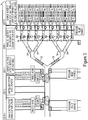
- an embodiment of the current invention includes a microfluidic chip 101, with a droplet formation section 102, a droplet splitting section 103 connected to the droplet formation section and a reagent injection section 104 fluidly connected the droplet splitting section.
- Embodiments of the current invention can be microfluidic chips that allow for parallel processing of sample droplets as seen in Figure 2.
- Figure 2 contrasts traditional linear design microfluidic chips (top panel) with an embodiment of the current invention which allows for parallel operation, processing and detection of sample droplets (bottom panel).
- sample droplets are subjected to bifurcation steps prior to injection with a reagent.
- bifurcation results in the formation of at least 4 daughter sample droplets.
- these daughter droplets are each injected with one of four reagents (R1, R2, R3, R4) to form a sample droplet plus reagent (S+R1, S+R2, S+R3, S+R4).
- sample plus reagent droplets are detected in parallel. This is in contrast to traditional approaches (top panel) where sample droplets are incubated with reagents (R4, R3, R2 and R1) to create sample plus reagent droplets (S+R4, S+R3, S+R2 and S+R1) in a linear manner.
- Step 1 The droplet platform (or microfluidic chip) is capable of accepting an unlimited number of samples from a multi-well plate. An unlimited number of samples can subsequently be loaded and processed; in this case at least 7 samples are represented by S1, S2, S3, S4, S5, S6 and S7. It can be seen from Figure 3 that samples 1-7 can be processed in a sequential order as their respective sample droplets (S1, S2, S3, S4, S5, S6 and S7) move through the channels.
- the droplet platform can be made capable of accepting an unlimited number of samples from a multi-well plate with a custom-build Serial Sample Loading (SSL) system.
- SSL Serial Sample Loading
- Step 2 Sample droplets are digitized into smaller daughter droplets of about ⁇ 30 nL in size. Once a sample has been processed, the sample inlet is rinsed prior to injection of new samples to prevent cross-contamination. Volume of sample droplets is controlled by valve opening time and back pressure on inlets. Pressure relief channels up- and down-stream (Pressure relief channel 1 and Pressure relief channel 2, respectively) contribute to droplet monodispersity by reducing downstream resistance. Step 3: Fission occurs as the daughter droplets flow through 3 serial bifurcating junctions and are split into 8 droplets. Flow is halted once the daughter droplets reach the reagent injection site by activating the oil valve. A third downstream pressure relief channel (Pressure relief channel 3) ensures homogeneous droplet splitting.
- Step 4 A library of reagents is then injected directly into the 8 sample daughter droplets simultaneously.
- probes R1, R2, R3, R4, R5, R6, R7 and R8 are injected directly into the droplets.
- Probe volume is controlled by valve opening time and back pressure on inlets.
- Step 5 Post-injection, the 8 sample-reagent drops are mixed in serpentine channels and flow through 2 additional serial bifurcating junctions, producing a total of 32 droplets of 8 unique compositions. Detection can be performed using imaging or parallel confocal fluorescence spectroscopy systems 3 .
- This entire sequence of operations is carried out in less than a second. Furthermore, the sequence of droplets is maintained on the droplet platform. This permits spatial indexing for droplet identification. This precludes the need to include barcodes in each droplet to identify its contents.
- sample embodiments described above involve regions with two different channel heights. Positive, shallow channels (25 ⁇ m) are incorporated near the sample introduction region and probe inlets to allow for valve actuation. The rest of the fluidic layer is 45 ⁇ m high.
- SPR220-7 Rohm & Haas, 25 ⁇ m
- SU-8 Microchem, 3000 series, 45 ⁇ m
- microfluidic chips illustrating the sample embodiment described above are fabricated using multilayer soft lithography techniques with a modified three-layer fabrication process. Soft lithography is used to make multiple devices from these molds.
- SYLGARD 184 Silicone Elastomer Kit is used for fabricating microfluidic chips illustrating an embodiment of the invention. The elastomer and curing agent from the kit is mixed in 10:1 (PDMS supportive material), 15:1 (fluidic), 7:1 (valve) ratio by weight and degassed for approximately 30 minutes before pouring on a respective molds. Once the individual PDMS layers have been assembled, the entire assembly is baked at 80°C for 20 minutes. The solidified polymer is then peeled off and cut into individual chips.
- Fluidic access holes are then punched into individual chips and the chips are bonded with cover glass (No. 1) using O2 plasma. All the devices were treated with Aquapel to render their surface hydrophobic.
- the carrier fluid used to maintain the separation between sample plugs consisted of a perfluorocarbon (FC-3283) and a non-ionic fluorous-soluble surfactant (1H,1H,2H,2H-perfluoro-1-octanol) mixed in a ratio of 4:1 by volume.
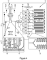
- Figure 4 and Figure 5 illustrate embodiments of the invention illustrated in Figures 2 and 3 and described above.
- Figure 4 shows a microfluidic chip capable of performing sample droplet generation, droplet splitting, droplet merging with probes and droplet detection on a single device.
- Figure 4 shows fluidic channels (121), valve layers (V1, V2, V3, V4, V5, V6, V7, V8) and oil inlet (Oil) connected to a central channel (or main channel) (122) with parallel fusion, fission and incubation regions (123).
- Two pressure relief channels near the sample inlets ensure that the initial sample droplets are monodisperse by decoupling droplet size from flow resistance of the incubation channel.
- a third pressure relief channel after the fission regions decouples droplet splitting performance from flow resistance of the incubation channel.
- Incubation channels are serpentine in design 128.
- FIG. 5 shows another embodiment of the microfluidic chip described above.
- the microfluidic device of Figure 5 employs a two-layer architecture where the flow of oil, sample droplets, and reagent droplets in the fluid layer is regulated by designated valves in a valve layer.
- the oil is pumped via its inlet into the central channel to drive droplet formation and flow.
- the central channel (122) where the droplet generation, bifurcation, fusion, and detection occur - undergoes several splits, connects with reagent inlet channels, and eventually divides into 32 channels with the same length and hence the same fluidic resistance.
- Two pressure relief channels near the sample inlets ensure the uniformity of sample droplets by decoupling droplet generation from fluidic resistance of the incubation channel.
- Sample droplets travel through the first three stages of bifurcating Y-junctions, producing a total of eight identical daughter droplets.
- Eight reagents can be injected via reagent inlets (reagent-injection channels) (R1 - R8) and directly fused with incoming sample daughter droplets.
- Fused sample-reagent droplets go through two additional bifurcating Y-junctions such that each injection of sample and reagents results in a total of 32 droplets (four replicates of eight different compositions).
- Each daughter droplet then flows through its serpentine incubation channel and arrives with all other daughter droplets in the same group simultaneously at the detection area, where all 32 channels become parallel and fit within a microscope viewing area, thus facilitating parallel detection via microscopy.
- sample droplets are formed in a series of steps as illustrated in Figure 6 .
- Step 1 a sample input channel 161 and a rinse channel 162 remain empty while valve 1 (rinsing channel valve) (163) and valve 2 (input channel valve) (164) remain closed.
- step 2 sample is loaded into the sample inlet while valve 1 remains in a closed configuration and valve 2 is in an open configuration.
- Step 3 the sample loading phase is completed and both valves are closed.
- Step 4 valve 1 is opened and a droplet is formed into the main channel 165.
- Step 5 valve 1 is closed and valve 2 is opened to allow for a rinse fluid to rinse the sample input channel. Used rinse fluid exits through the rinse channel.
- Steps 2-4 is repeated in Steps 6-8 with either the same sample or a different sample.
- Microfluidic chips illustrated in Figure 4 and Figure 5 and described above were then used for sample droplet preparation and processing. All the inputs on the devices were kept under constant pressure, with independent input pressures for 1) carrier fluid input, 2) both sample inlets and 3) all 8 probe inputs. The pressure applied to the sample inlets was directly controlled by the pressure controller used for the SSL system. All the valves on the device were controlled by an array of off-chip solenoid valves, as has been demonstrated earlier. We developed Matlab (Mathworks, Natick MA) software for computer control of the valve array. This software allowed us to execute a predetermined sequence of valve actuation with independent time control for each actuation.
- the opening of a valve corresponding to an input on the device led to the release of a sample droplet of fluid from that inlet into a central channel on the device.
- the volume of this droplet could be controlled through variation of the opening time of the valve as well as the back pressure.
- the volume of sample and probe droplets generated using the microfluidic device were estimated. This volume estimation was performed by processing the images of these droplets using the software ImageJ.
- sample droplet volume estimation we generated droplets made of blue food dye using one of the four reagent inlets on the microfluidic devices, until the whole incubation region on the devices were full of droplets.
- the whole device was then imaged using a DSLR camera.
- the image was imported in ImageJ and cropped to obtain an image of the incubation region on the device.
- This image was then converted to a binary image using color thresholding to identify droplets over the background image.
- An estimate of the droplet area for each droplet in the image was then obtained using the 'Analyze Particles' function. This analysis was limited to particle areas larger than a lower threshold to exclude any particles and occasional satellite droplets from the analysis.
- the droplet areas thus estimated were then converted to droplet volume using the known depth of the incubation channel region (200 ⁇ m).
- the device exhibits excellent sample droplet uniformity for identical droplet generation and fission conditions.
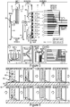
- the fine control of droplet size generated on the device from an individual sample inlet through variation of pressure and valve opening time is demonstrated in Figure 7 .
- final droplet size after fission was measured.
- a unique feature of the device is 3 pressure relief channels.
- the pressure relief channels decouple both 1) the dependence of initial droplet size generated as well as 2) fission of droplets on the device from the flow resistance of the incubation channel.
- the left panel shows a micrograph of a section of fission and incubation regions of the device and shows sample droplets containing green food dye being split and incubated.
- the top middle graph of Figure 7 is a plot of sample droplet volume dependence on valve opening time and back pressure.
- Droplet volume was measured after droplet fission. Droplet volume varies linearly with the valve opening time. Small error bars indicate monodispersity.
- the bottom middle panel is a histogram of sample droplet volumes (valve opening time .05 seconds). Histograms are overlayed with Kernel density plots. Three datasets are visible: droplet volumes for 13789.5 Pascal (2 PSI), 20684.3 Pascal (3 PSI) and 27579 Pascal (4 PSI). All populations of droplets have a narrow distribution indicating monodispersity and are well-separated (no overlap in droplet volumes).
- the top right graph is a plot of probe droplet volume dependence on valve opening time and back pressure. Droplet volume was measured after droplet fission. Droplet volume varies linearly with the valve opening time.
- the bottom right graph is an example of histogram of probe droplet volumes (valve opening time .05 seconds). Histograms are overlayed with Kernel density plots. Four datasets are visible: droplet volumes for 13789.5 Pascal (2 PSI), 20684.3 Pascal (3 PSI), 27579 Pascal (4 PSI) and 34473.8 Pascal (5 PSI). All populations of droplets have a narrow distribution indicating monodispersity and are well-separated (no overlap in droplet volumes).
- FIG. 8 Generation of 8 combinatorial mixtures of sample plugs and probes on the device is shown in Figure 8 .
- different fluorophores with varying concentrations were used (FITC, Cy5, DI H 2 O) to simulate different samples and probes.
- the top left panel shows reagent injection: Fluorescent micrograph of sample droplet (green: FITC - 1 ⁇ M) at reagent (Cy5 - 5 ⁇ M) injection inlet.
- the top right panel displays merged sample-reagent droplets in incubation region. Top 4 rows of droplets were injected with Reagent 8 (Cy5 - 10 ⁇ M). Bottom 4 rows were injected with Reagent 7 (Cy5 - 5 ⁇ M).
- the bottom panel shows fluorescent micrographs of combinatorial droplets: the upper row displays droplets containing only reagents (R1-R8) and the bottom panel displays merged sample (1 ⁇ M FITC) and reagent (R1-R8) droplets.
- Droplets are able to split into equal halves - as indicated by the -50% bifurcation efficiency across all five bifurcation stages.
- Insert micrographs show droplets, which are colored with black food dye for enhanced visualization, about to split into equal halves at the five bifurcation stages.
- the scale bar below each micrograph represents 500 ⁇ m.
- FIG. 12 Imaging-Based Parallel Detection of Fused Droplets is shown in Figure 12 .
- Each of the eight fused sample-reagent droplets undergoes two additional bifurcations, which results in four replicates of fused daughter droplets. After incubation, these droplets are detected in parallel in the detection zone.
- the scale bar represents 500 ⁇ m.
- each of the reagent inlet channels are outfitted with individual rinse channels and valves (as described for the sample inlet channels above and in Figures 3-6 ) so that the reagent inlet channels can be rinsed prior to subsequent uses.
- sample inlet channels work in an alternating manner such that while a first sample input channel is providing a sample droplet, an alternative sample input channel is rinsed and subsequently loaded with either an additional aliquot of the sample or an aliquot of a different sample. Once the first sample input channel has provided a sample droplet, it is rinsed while the second sample input channel provides a sample droplet. The process is repeated.
- additional sections for creating chaotic mixes are also included so as to mix sample and/or sample-reagent droplets.
- Step 1 The droplet platform can be made capable of accepting an unlimited number of samples from a multi-well plate with a custom-build Serial Sample Loading (SSL) system (also described in Figure 14 and Figure 15, top panel).
- Step 2 Sample droplets are digitized into smaller daughter droplets (-30 nL).
- Step 3 Fission occurs as the daughter droplets flow through 3 serial bifurcating junctions and are split into 8 droplets. Flow is halted once the daughter droplets reach the probe injection site by activating the oil valve.
- Step 4 A library of probes is then injected directly into the 8 sample daughter droplets simultaneously.
- Step 5 Post-injection, the 8 sample-probe drops are mixed in serpentine channels and flow through 2 additional serial bifurcating junctions, producing a total of 32 droplets of 8 unique compositions. This entire sequence of operations is carried out in less than a second. Furthermore, the sequence of droplets is maintained on the device. This permits spatial indexing for droplet identification. This precludes the need to include barcodes in each droplet to identify its contents.
- an automated sample loading system (such as an autosampler or robotic pipetter) is connected to the sample input channels as is seen in Figure 13 .
- This can allow for an unlimited number of samples to be processed as well as automation of the device.
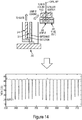
- channels are rinsed using rinsing channels built into the device to prevent cross-contamination ( Figure 14 , top panel).
- sample is loaded from a sample reservoir (240) to an input channel (241).
- the input channel is rinsed with rinse liquid from a rinse liquid reservoir (243) and the rinse fluid exits the input channel from a waste channel (244).
- the autosampler or robotic pipetter can also fitted with a capillary, a capillary adapter and a rubber sealing ring to facilitate sample loading and input channel rinsing.
- pressure relief channels are coupled to the invention. These pressure relief channels are opened when droplets are being generated, which in turn leads to monodisperse droplets. Size analysis based on the area of the droplets indicates that droplets exhibit excellent monodispersity.
- a novel combination of droplet splitting and post-splitting reagent injection is coupled to the invention. This can allow the droplet generation process to be highly parallelized.
- a single sample plug is split into 8 daughter droplets. 8 different reagents are injected in parallel directly into the droplets. Additional splitting after reagent injection creates four replicate droplets from reach unique combination, 32 droplets total. It is important to note that the particular device describe here is one embodiment of a concept that can be varied to fit a wide range of needs by changing the number or arrangement of channels, ports, valves, number of stages of splitting, etc.
- sample-probe droplets are maintained in a single file configuration, thus precluding the need for a barcoding mechanism to identify the contents of each individual droplet.
- an impedance detection system is connected to the sample input channels.
- the impedance detection system functions by optically monitoring the contents of the sample input channels and the rinsing channels for automated detection of sample or rinsing fluid. If the channels contain sample, the impedance system feedbacks to a controller to direct the release of the sample fluid into the main channel for generation of a sample droplet. Alternatively, if rinse fluid is contained in the channels, the impedance system feedbacks to the controller to direct the release of the rinse fluid through the rinse channel.
- the impedance system provides readout of the contents of the channels while the device is in use as can be seen in Figure 14 , bottom panel.
- Such an impedance system can also be added to the reagent injection channels to determine the contents of these channels and direct either their rinsing or reagent injection.
- the examples described above of on-demand, parallelized nano-liter droplet-based platforms and devices that accept an unlimited number of sample plugs from a multi-well plate, digitizes these plugs into smaller daughter droplets, performs droplet splitting and robust synchronization-free fusion with a library of probes in parallel are sample embodiments of the current invention.
- the sequence of sample-probe droplets on the device is maintained, permitting spatial indexing to identify droplet contents.
- the devices described above combine the precision of valve-based devices while featuring increased throughput.
- the on-demand platform described above meets the demand for flexible and cost-effective tools that can perform high throughput screening for next generation applications.
Landscapes
- Chemical & Material Sciences (AREA)
- Health & Medical Sciences (AREA)
- Organic Chemistry (AREA)
- Chemical Kinetics & Catalysis (AREA)
- Dispersion Chemistry (AREA)
- Clinical Laboratory Science (AREA)
- Hematology (AREA)
- General Health & Medical Sciences (AREA)
- Analytical Chemistry (AREA)
- Biochemistry (AREA)
- Molecular Biology (AREA)
- Medicinal Chemistry (AREA)
- General Chemical & Material Sciences (AREA)
- Life Sciences & Earth Sciences (AREA)
- Structural Engineering (AREA)
- Engineering & Computer Science (AREA)
- Automatic Analysis And Handling Materials Therefor (AREA)
- Apparatus Associated With Microorganisms And Enzymes (AREA)
- Measuring Or Testing Involving Enzymes Or Micro-Organisms (AREA)
Claims (11)
- Ein mikrofluidisches System, das Folgendes beinhaltet:
einen mikrofluidischen Chip (101), der einen Chipkörper beinhaltet, der Folgendes definiert:einen Tröpfchenbildungsabschnitt (102), der Folgendes beinhaltet:einen Hauptkanal (122, 165),einen Probeneingabekanal (124, 161), der ein erstes Ende, das mit dem Hauptkanal (122, 165) fluidisch verbunden ist, und ein zweites Ende, das konfiguriert ist, um Proben- und Spülfluid aufzunehmen, aufweist,ein Eingabekanalventil (164) in dem Probeneingabekanal (124, 161), um Fluidfluss von dem Probeneingabekanal (124, 161) zu dem Hauptkanal (122, 165) selektiv zu gestatten und abzusperren,einen Spülkanal (126, 162), der an einer Stelle zwischen dem Eingabekanalventil (164) und dem zweiten Ende des Probeneingabekanals (124, 161) mit dem Probeneingabekanal (124, 161) fluidisch verbunden ist,ein Spülkanalventil (163) in dem Spülkanal (126, 162), um Fluidfluss von dem Probeneingabekanal (124, 161) zu dem Spülkanal (126, 162) selektiv zu gestatten und abzusperren; undeine Anordnung von chipexternen Magnetventilen, um die Ventile zu steuern;wobei durch eine Computersteuerung eine vorgegebene Ventilbetätigungsreihenfolge mit unabhängiger Zeitsteuerung für jede Betätigung auf der Ventilanordnung ausführbar ist, wobei der Tröpfchenbildungsabschnitt (102) eine erste Konfiguration, in der das Eingabekanalventil (164) geöffnet ist und das Spülkanalventil (163) geschlossen ist, aufweist, um in dem Hauptkanal (122, 165) ein in einem inerten Fluid suspendiertes Probentröpfchen, das ein vorgegebenes Volumen aufweist, bereitzustellen, und wobei der Tröpfchenbildungsabschnitt (102) eine zweite Konfiguration, in der das Eingabekanalventil (164) geschlossen ist und das Spülkanalventil (163) geöffnet ist, aufweist, sodass Spülfluid den Probeneingabekanal (124, 161) mit einem durch den Probeneingabekanal (124, 161) hindurch und aus dem Spülkanal (126, 162) heraus verlaufenden Fluss des Spülfluids spült;einen Tröpfchenspaltungsabschnitt (103), der mit dem Hauptkanal (122, 165) des Tröpfchenbildungsabschnitts (102) fluidisch verbunden ist, um das Probentröpfchen von dem Hauptkanal (122, 165) aufzunehmen und das Probentröpfchen in eine Vielzahl von Tochtertröpfchen zu spalten, die von dem Tröpfchenspaltungsabschnitt (103) ausgegeben werden sollen;eine Vielzahl von Nebenkanälen, wobei die Vielzahl von Tochtertröpfchen von dem Tröpfchenspaltungsabschnitt (103) in einem jeweiligen der Vielzahl von Nebenkanälen ausgegeben wird; undeinen Reagenzeinspritzabschnitt (104), der mit jedem der Vielzahl von Nebenkanälen fluidisch verbunden ist und eine entsprechende Vielzahl von Reagenzeinspritzkanälen aufweist, die derart eingerichtet sind, dass jedes Reagenz einer Vielzahl von Reagenzien gleichzeitig in ein jeweiliges der Vielzahl von Tochtertröpfchen einspritzbar ist, während sich die Tochtertröpfchen in der Vielzahl von Nebenkanälen aufhalten, um eine Vielzahl von Proben-Reagenz-Tröpfchen bereitzustellen, die in einem entsprechenden einer Vielzahl von Ausgabekanälen ausgegeben werden,wobei die Vielzahl von Ausgabekanälen mit der Vielzahl von Nebenkanälen fluidisch verbunden ist und konfiguriert ist, um die Vielzahl von Proben-Reagenz-Tröpfchen aufzunehmen, undwobei der Tröpfchenbildungsabschnitt (102) einen Druckentlastungskanal beinhaltet, um Druck auf die Probentröpfchen während ihrer Bildung steuerbar zu regulieren;eine erste Probenquelle (240), die mit dem Probeneingabekanal (124, 161) selektiv verbunden ist;eine zweite Probenquelle (240), die mit dem Probeneingabekanal (124, 161) selektiv verbunden ist;eine Spülfluidquelle (243), die mit dem Probeneingabekanal (124, 161) selektiv verbunden ist, undein Impedanzerfassungssystem, das mit dem mikrofluidischen Chip (101) fluidisch verbunden ist. - Mikrofluidisches System gemäß Anspruch 1, wobei das mikrofluidische System ferner ein automatisiertes Probenladesystem beinhaltet, das mit dem mikrofluidischen Chip (101) fluidisch verbunden ist.
- Mikrofluidisches System gemäß Anspruch 1, wobei der Tröpfchenbildungsabschnitt (102) des mikrofluidischen Chips (101) ferner Folgendes beinhaltet:einen zweiten Probeneingabekanal (125), der ein erstes Ende, das mit dem Hauptkanal (122, 165) fluidisch verbunden ist, und ein zweites Ende, das konfiguriert ist, um Proben- und Spülfluid aufzunehmen, aufweist,ein Eingabekanalventil (164) in dem zweiten Probeneingabekanal (125), um Fluidfluss von dem zweiten Probeneingabekanal (125) zu dem Hauptkanal (122, 165) selektiv zu gestatten und abzusperren,einen zweiten Spülkanal (127), der an einer Stelle zwischen dem Eingabekanalventil (164) und dem zweiten Ende des zweiten Probeneingabekanals (125) mit dem zweiten Probeneingabekanal (125) fluidisch verbunden ist, undein Spülkanalventil (163) in dem zweiten Spülkanal (127), um Fluidfluss von dem zweiten Eingabekanal (125) zu dem zweiten Spülkanal (127) selektiv zu gestatten und abzusperren,wobei der Tröpfchenbildungsabschnitt (102) in der vorgegebenen Ventilbetätigungsreihenfolge, die durch die Computersteuerung ausführbar ist, eine dritte Konfiguration, in der das Eingabekanalventil (164) des zweiten Probeneingabekanals (125) geöffnet ist und das Spülkanalventil (163) des zweiten Spülkanals (127) geschlossen ist, aufweist, um in dem Hauptkanal (122, 165) ein in einem inerten Fluid suspendiertes Probentröpfchen, das ein vorgegebenes Volumen aufweist, bereitzustellen, und wobei der Tröpfchenbildungsabschnitt (102) eine vierte Konfiguration, in der das Eingabekanalventil (164) des zweiten Probeneingabekanals (125) geschlossen ist und das Spülkanalventil (163) des zweiten Spülkanals (127) geöffnet ist, aufweist, sodass Spülfluid den zweiten Probeneingabekanal (125) mit einem durch den zweiten Probeneingabekanal (125) hindurch und aus dem zweiten Spülkanal (127) heraus verlaufenden Fluss des Spülfluids spült.
- Mikrofluidisches System gemäß Anspruch 3, wobei die Eingabekanäle des mikrofluidischen Chips (101) in einer alternierenden Art und Weise arbeiten, sodass, während ein erster der Eingabekanäle konfiguriert ist, um ein Probentröpfchen in den Hauptkanal (122, 165) bereitzustellen, ein zweiter der Eingabekanäle gleichzeitig zum Spülen konfiguriert ist, und wobei im Anschluss an die Probentröpfchenbildung durch den ersten der Eingabekanäle der erste der Probeneingabekanäle (124) zum Spülen konfiguriert ist und der zweite der Probeneingabekanäle (125) gleichzeitig konfiguriert ist, um ein Probentröpfchen in den Hauptkanal (122, 165) bereitzustellen.
- Mikrofluidisches System gemäß Anspruch 1 oder 3, wobei der Reagenzeinspritzabschnitt (104) des mikrofluidischen Chips (101) einen Druckentlastungskanal beinhaltet, um Druck auf die Vielzahl von Tochtertröpfchen steuerbar zu regulieren, während jedes der Vielzahl von Reagenzien in ein entsprechendes der Vielzahl von Tochtertröpfchen eingespritzt wird.
- Mikrofluidisches System gemäß Anspruch 1 oder 3, wobei der mikrofluidische Chip (101) ferner einen Proben-Reagenz-Tröpfchenspaltungsabschnitt beinhaltet, der mit jedem der Vielzahl von Ausgabekanälen fluidisch verbunden ist, um die Vielzahl von Proben-Reagenz-Tröpfchen aufzunehmen und jedes der Proben-Reagenz-Tröpfchen in eine Vielzahl von Proben-Reagenz-Tochtertröpfchen zu spalten, die von dem Proben-Reagenz-Tröpfchenspaltungsabschnitt in einem jeweiligen einer Vielzahl von zweiten Ausgabekanälen ausgegeben werden sollen.
- Mikrofluidisches System gemäß einem der Ansprüche 1, 3 und 6, wobei der Proben-Reagenz-Tröpfchenspaltungsabschnitt des mikrofluidischen Chips (101) ein mehrstufiger Tröpfchenspalter ist.
- Mikrofluidisches System gemäß Anspruch 1 oder 3, von wobei der mikrofluidische Chip (101) ferner einen Inkubationsabschnitt (123) beinhaltet, der derart mit jedem der Vielzahl von Ausgabekanälen fluidisch verbunden ist, dass jedes der Proben-Reagenz-Tröpfchen in einen jeweiligen einen Inkubationskanal (128) fließt, um identifizierbare Proben- und Reagenzdaten davon zu bewahren.
- Mikrofluidisches System gemäß Anspruch 8, wobei die Inkubationskanäle (128) des mikrofluidischen Chips (101) die gleiche Länge haben.
- Mikrofluidisches System gemäß Anspruch 1 oder 3, wobei der Reagenzeinspritzabschnitt (104) des mikrofluidischen Chips (101) ferner Folgendes beinhaltet:ein Reagenzeinspritzventil in jedem der Reagenzeinspritzkanäle, um Fluidfluss von jedem der Reagenzeinspritzkanäle zu der Vielzahl von Nebenkanälen selektiv zu gestatten und abzusperren,einen Spülkanal, der mit jedem der Vielzahl von Reagenzeinspritzkanälen fluidisch verbunden ist, undein Spülkanalventil in dem Spülkanal, um Fluidfluss von jedem der Vielzahl von Reagenzeinspritzkanälen zu dem Spülkanal selektiv zu gestatten und abzusperren, wobei der Reagenzeinspritzabschnitt (104) in der vorgegebenen Ventilbetätigungsreihenfolge, die durch die Computersteuerung ausführbar ist, eine erste Konfiguration, in der das Reagenzeinspritzventil in jedem der Vielzahl von Reagenzeinspritzkanälen geöffnet ist und das Spülkanalventil in dem Spülkanal geschlossen ist, aufweist, um in der Vielzahl von Nebenkanälen ein Reagenz bereitzustellen, und wobei der Reagenzeinspritzabschnitt (104) eine zweite Konfiguration, in der das Reagenzeinspritzventil in jedem der Vielzahl von Reagenzeinspritzkanälen geschlossen ist und das Spülkanalventil in dem Spülkanal geöffnet ist, aufweist, sodass Spülfluid jeden der Vielzahl von Reagenzeinspritzkanälen mit einem durch jeden der Vielzahl von Reagenzeinspritzkanälen hindurch und aus dem Spülkanal in jedem der Vielzahl von Reagenzeinspritzkanälen heraus verlaufenden Fluss des Spülfluids spült.
- Mikrofluidisches System gemäß Anspruch 1 oder 3, wobei der mikrofluidische Chip (101) ferner einen Abschnitt mit Erfassungskanälen beinhaltet, wobei die Erfassungskanäle für optische Messungen mindestens teilweise transparent sind.
Applications Claiming Priority (2)
| Application Number | Priority Date | Filing Date | Title |
|---|---|---|---|
| US201461931516P | 2014-01-24 | 2014-01-24 | |
| PCT/US2015/012927 WO2015112985A1 (en) | 2014-01-24 | 2015-01-26 | System and device for high throughput generation of combinatorial droplets and methods of use |
Publications (3)
| Publication Number | Publication Date |
|---|---|
| EP3096882A1 EP3096882A1 (de) | 2016-11-30 |
| EP3096882A4 EP3096882A4 (de) | 2017-09-20 |
| EP3096882B1 true EP3096882B1 (de) | 2021-05-05 |
Family
ID=53682025
Family Applications (1)
| Application Number | Title | Priority Date | Filing Date |
|---|---|---|---|
| EP15739970.0A Active EP3096882B1 (de) | 2014-01-24 | 2015-01-26 | System und vorrichtung zur hochdurchsatz-erzeugung von kombinatorischen tröpfchen |
Country Status (8)
| Country | Link |
|---|---|
| US (1) | US10406520B2 (de) |
| EP (1) | EP3096882B1 (de) |
| CN (1) | CN106029233B (de) |
| BR (1) | BR112016017155A2 (de) |
| CA (1) | CA2937784C (de) |
| CL (1) | CL2016001867A1 (de) |
| ES (1) | ES2876264T3 (de) |
| WO (1) | WO2015112985A1 (de) |
Cited By (1)
| Publication number | Priority date | Publication date | Assignee | Title |
|---|---|---|---|---|
| DE102024117886A1 (de) * | 2024-06-25 | 2026-01-08 | NORGANOID Ltd. | Mikrofluidisches Chip-System |
Families Citing this family (23)
| Publication number | Priority date | Publication date | Assignee | Title |
|---|---|---|---|---|
| US12290811B2 (en) | 2015-01-23 | 2025-05-06 | Unchained Labs | Microfluidic serial dilution platform based well-plate using an oil-free immiscible phase driven by manual or electronic pipettors |
| WO2017031438A1 (en) * | 2015-08-19 | 2017-02-23 | The Texas A & M University System | Microfluidic platform device and method for identifying neutralizing and/or enhancing antibodies through direct functional assays |
| JP2018537663A (ja) * | 2015-11-06 | 2018-12-20 | コーニンクレッカ フィリップス エヌ ヴェKoninklijke Philips N.V. | モジュラー流体検知システム |
| WO2018148693A1 (en) * | 2017-02-13 | 2018-08-16 | Bio-Rad Laboratories, Inc. | System, method, and device for forming an array of emulsions |
| US11059043B2 (en) * | 2017-04-19 | 2021-07-13 | The Johns Hopkins University | Impedance based feedback control of microfluidic valves |
| WO2018200896A1 (en) | 2017-04-28 | 2018-11-01 | Neofluidics, Llc | Fluidic devices with reaction wells and uses thereof |
| WO2018204150A1 (en) * | 2017-05-02 | 2018-11-08 | Wu Guikai | Method and system for reference-assisted droplet detection, indexing and sorting for assays and diagnostics |
| EP4215616B1 (de) | 2017-05-18 | 2024-09-04 | 10X Genomics, Inc. | Verfahren und systeme zum sortieren von tröpfchen und kügelchen |
| US10544413B2 (en) | 2017-05-18 | 2020-01-28 | 10X Genomics, Inc. | Methods and systems for sorting droplets and beads |
| WO2019032690A1 (en) | 2017-08-09 | 2019-02-14 | Neofluidics, Llc | Devices and methods for bioassay |
| US10357771B2 (en) | 2017-08-22 | 2019-07-23 | 10X Genomics, Inc. | Method of producing emulsions |
| WO2019083852A1 (en) | 2017-10-26 | 2019-05-02 | 10X Genomics, Inc. | MICROFLUIDIC CHANNEL NETWORKS FOR PARTITIONING |
| CN109746059B (zh) * | 2017-11-06 | 2024-04-12 | 北京新羿生物科技有限公司 | 微液滴生成系统 |
| CA3082074A1 (en) * | 2017-11-10 | 2019-05-16 | Neofluidics, Llc | Integrated fluidic circuit and device for droplet manipulation and methods thereof |
| JP2019144164A (ja) * | 2018-02-22 | 2019-08-29 | 株式会社エンプラス | 流体取扱装置 |
| EP3870369A4 (de) | 2018-10-26 | 2022-11-09 | Neofluidics, LLC | Fluidische vorrichtungen mit reaktionsmulden und verengungskanälen und verwendungen davon |
| CN109289951B (zh) * | 2018-10-29 | 2021-01-05 | 深圳先进技术研究院 | 液滴分裂微流控芯片及应用 |
| EP3930900A1 (de) | 2019-02-28 | 2022-01-05 | 10X Genomics, Inc. | Vorrichtungen, systeme und verfahren zur erhöhung der tröpfchenbildungseffizienz |
| ES3066039T3 (en) * | 2019-12-04 | 2026-05-11 | Astraveus | Microfluidic device and method for processing particles |
| CN111841669B (zh) * | 2020-06-19 | 2023-10-20 | 华中科技大学同济医学院附属同济医院 | 一种用于微生物检测的pcr芯片及基于该pcr芯片的液滴分配方法 |
| US12097494B2 (en) * | 2020-09-17 | 2024-09-24 | Mayo Foundation For Medical Education And Research | Methods, devices, and systems for detecting two or more analytes within small volumes |
| CN116139946B (zh) * | 2021-11-19 | 2025-11-14 | 深圳华大生命科学研究院 | 微流控装置及其制作方法 |
| CN117548165B (zh) * | 2023-10-26 | 2025-11-21 | 余姚市机器人研究中心 | 一种基于微流控反馈阀的均匀液滴生成装置 |
Family Cites Families (15)
| Publication number | Priority date | Publication date | Assignee | Title |
|---|---|---|---|---|
| JP2004208152A (ja) | 2002-12-26 | 2004-07-22 | Mitsubishi Electric Corp | 遅延回路 |
| US7595195B2 (en) | 2003-02-11 | 2009-09-29 | The Regents Of The University Of California | Microfluidic devices for controlled viscous shearing and formation of amphiphilic vesicles |
| JP3778290B2 (ja) * | 2003-07-29 | 2006-05-24 | 船井電機株式会社 | 光ディスク再生装置 |
| US20050176135A1 (en) * | 2004-02-06 | 2005-08-11 | Brian Jones | Cassette for isolation, amplification and identification of DNA or protein and method of use |
| EP1746158A4 (de) * | 2004-05-07 | 2009-11-25 | Konica Minolta Med & Graphic | Mikroreaktor zum testen, genetische testvorrichtung und genetisches testverfahren |
| US20060153745A1 (en) | 2005-01-11 | 2006-07-13 | Applera Corporation | Fluid processing device for oligonucleotide synthesis and analysis |
| US8257964B2 (en) | 2006-01-04 | 2012-09-04 | Cell ASIC | Microwell cell-culture device and fabrication method |
| US7811603B2 (en) | 2006-05-09 | 2010-10-12 | The Regents Of The University Of California | Microfluidic device for forming monodisperse lipoplexes |
| EP2530168B1 (de) * | 2006-05-11 | 2015-09-16 | Raindance Technologies, Inc. | Mikrofluidische Vorrichtungen |
| DE102009032820A1 (de) * | 2009-07-13 | 2011-01-20 | Mitsubishi Polyester Film Gmbh | Ein- oder mehrschichtige, stabilisierte Polyesterfolie |
| US9625454B2 (en) | 2009-09-04 | 2017-04-18 | The Research Foundation For The State University Of New York | Rapid and continuous analyte processing in droplet microfluidic devices |
| US9376713B2 (en) * | 2009-09-23 | 2016-06-28 | The Board Of Trustees Of The University Of Illinois | Label free detection of nucleic acid amplification |
| WO2012109138A1 (en) * | 2011-02-07 | 2012-08-16 | President And Fellows Of Harvard College | Systems and methods for splitting droplets |
| US10222391B2 (en) * | 2011-12-07 | 2019-03-05 | The Johns Hopkins University | System and method for screening a library of samples |
| DK2829882T3 (da) | 2012-03-21 | 2020-05-18 | Nec Corp | Chip til analyse af en målsubstans |
-
2015
- 2015-01-26 EP EP15739970.0A patent/EP3096882B1/de active Active
- 2015-01-26 US US15/112,334 patent/US10406520B2/en active Active
- 2015-01-26 BR BR112016017155A patent/BR112016017155A2/pt active Search and Examination
- 2015-01-26 WO PCT/US2015/012927 patent/WO2015112985A1/en not_active Ceased
- 2015-01-26 CN CN201580009203.XA patent/CN106029233B/zh not_active Expired - Fee Related
- 2015-01-26 ES ES15739970T patent/ES2876264T3/es active Active
- 2015-01-26 CA CA2937784A patent/CA2937784C/en active Active
-
2016
- 2016-07-22 CL CL2016001867A patent/CL2016001867A1/es unknown
Cited By (1)
| Publication number | Priority date | Publication date | Assignee | Title |
|---|---|---|---|---|
| DE102024117886A1 (de) * | 2024-06-25 | 2026-01-08 | NORGANOID Ltd. | Mikrofluidisches Chip-System |
Also Published As
| Publication number | Publication date |
|---|---|
| US20160332163A1 (en) | 2016-11-17 |
| EP3096882A4 (de) | 2017-09-20 |
| CL2016001867A1 (es) | 2016-12-30 |
| WO2015112985A1 (en) | 2015-07-30 |
| CA2937784C (en) | 2022-08-23 |
| BR112016017155A2 (pt) | 2017-08-08 |
| CN106029233B (zh) | 2018-10-23 |
| ES2876264T3 (es) | 2021-11-12 |
| CA2937784A1 (en) | 2015-07-30 |
| EP3096882A1 (de) | 2016-11-30 |
| CN106029233A (zh) | 2016-10-12 |
| US10406520B2 (en) | 2019-09-10 |
Similar Documents
| Publication | Publication Date | Title |
|---|---|---|
| CA2937784C (en) | System and device for high throughput generation of combinatorial droplets and methods of use | |
| Yang et al. | Engineered tools to study intercellular communication | |
| Chiu et al. | Small but perfectly formed? Successes, challenges, and opportunities for microfluidics in the chemical and biological sciences | |
| US10739366B2 (en) | System and method for screening a library of samples | |
| Melin et al. | Microfluidic large-scale integration: the evolution of design rules for biological automation | |
| Vyawahare et al. | Miniaturization and parallelization of biological and chemical assays in microfluidic devices | |
| Jin et al. | A programmable microfluidic static droplet array for droplet generation, transportation, fusion, storage, and retrieval | |
| US20140208832A1 (en) | Methods and Apparatus for Flow-Controlled Wetting | |
| US10239057B2 (en) | Microfluidic devices and methods for cell analysis and molecular diagnostics | |
| EP2412020B1 (de) | Schiebe- und schneidevorrichtung und entsprechende verfahren | |
| Zec et al. | Microfluidic platform for on-demand generation of spatially indexed combinatorial droplets | |
| CN107407691A (zh) | 用于单细胞中核酸靶标的分子条码化的装置和系统 | |
| Schneider et al. | Self-digitization of samples into a high-density microfluidic bottom-well array | |
| US20170355950A1 (en) | Systems for dissociation of biological tissues | |
| US20240401026A1 (en) | System and method for single cell phenotypical profiling and deterministic nanoliter-droplet encapsulation and deterministic droplet consortia assemblies | |
| Cui et al. | A multiplexable microfluidic injector for versatile encoding of droplets | |
| WO2013021035A1 (en) | Microfluids for cell-based assays | |
| Zec et al. | Parallelization offissionand fusion+ operations for high throughput generation of combinatorial droplets | |
| Harriot et al. | Programmable Control of Nanoliter Droplet Arrays Using Membrane Displacement Traps | |
| EP3094740B1 (de) | Analyseeinheit zum durchführen einer verschachtelten polymerasekettenreaktion, analysevorrichtung, verfahren zum betreiben einer solchen analyseeinheit und verfahren zum herstellen einer solchen analyseeinheit | |
| US11998912B2 (en) | Tubing-free, sample-to-droplet microfluidic system and chip | |
| Fletcher | Quantification of membrane transport rates using optofluidics | |
| Bahnemann et al. | Special Laboratory Reactors: Lab-on-a-Chip | |
| Zhang | Microfluidic tools for connecting single-cell optical and gene expression phenotype | |
| Occhetta et al. | Microfluidic Platform for Adherent Single Cell High-Throughput Screening |
Legal Events
| Date | Code | Title | Description |
|---|---|---|---|
| PUAI | Public reference made under article 153(3) epc to a published international application that has entered the european phase |
Free format text: ORIGINAL CODE: 0009012 |
|
| 17P | Request for examination filed |
Effective date: 20160801 |
|
| AK | Designated contracting states |
Kind code of ref document: A1 Designated state(s): AL AT BE BG CH CY CZ DE DK EE ES FI FR GB GR HR HU IE IS IT LI LT LU LV MC MK MT NL NO PL PT RO RS SE SI SK SM TR |
|
| AX | Request for extension of the european patent |
Extension state: BA ME |
|
| DAX | Request for extension of the european patent (deleted) | ||
| A4 | Supplementary search report drawn up and despatched |
Effective date: 20170821 |
|
| RIC1 | Information provided on ipc code assigned before grant |
Ipc: C40B 50/08 20060101ALI20170814BHEP Ipc: B01J 19/00 20060101ALI20170814BHEP Ipc: B01L 3/00 20060101AFI20170814BHEP Ipc: C40B 60/08 20060101ALI20170814BHEP |
|
| STAA | Information on the status of an ep patent application or granted ep patent |
Free format text: STATUS: EXAMINATION IS IN PROGRESS |
|
| 17Q | First examination report despatched |
Effective date: 20190417 |
|
| GRAP | Despatch of communication of intention to grant a patent |
Free format text: ORIGINAL CODE: EPIDOSNIGR1 |
|
| STAA | Information on the status of an ep patent application or granted ep patent |
Free format text: STATUS: GRANT OF PATENT IS INTENDED |
|
| INTG | Intention to grant announced |
Effective date: 20201209 |
|
| GRAS | Grant fee paid |
Free format text: ORIGINAL CODE: EPIDOSNIGR3 |
|
| GRAA | (expected) grant |
Free format text: ORIGINAL CODE: 0009210 |
|
| STAA | Information on the status of an ep patent application or granted ep patent |
Free format text: STATUS: THE PATENT HAS BEEN GRANTED |
|
| AK | Designated contracting states |
Kind code of ref document: B1 Designated state(s): AL AT BE BG CH CY CZ DE DK EE ES FI FR GB GR HR HU IE IS IT LI LT LU LV MC MK MT NL NO PL PT RO RS SE SI SK SM TR |
|
| REG | Reference to a national code |
Ref country code: GB Ref legal event code: FG4D |
|
| REG | Reference to a national code |
Ref country code: CH Ref legal event code: EP |
|
| REG | Reference to a national code |
Ref country code: AT Ref legal event code: REF Ref document number: 1389115 Country of ref document: AT Kind code of ref document: T Effective date: 20210515 |
|
| REG | Reference to a national code |
Ref country code: IE Ref legal event code: FG4D |
|
| REG | Reference to a national code |
Ref country code: DE Ref legal event code: R096 Ref document number: 602015068955 Country of ref document: DE |
|
| REG | Reference to a national code |
Ref country code: LT Ref legal event code: MG9D |
|
| REG | Reference to a national code |
Ref country code: AT Ref legal event code: MK05 Ref document number: 1389115 Country of ref document: AT Kind code of ref document: T Effective date: 20210505 |
|
| PG25 | Lapsed in a contracting state [announced via postgrant information from national office to epo] |
Ref country code: BG Free format text: LAPSE BECAUSE OF FAILURE TO SUBMIT A TRANSLATION OF THE DESCRIPTION OR TO PAY THE FEE WITHIN THE PRESCRIBED TIME-LIMIT Effective date: 20210805 Ref country code: AT Free format text: LAPSE BECAUSE OF FAILURE TO SUBMIT A TRANSLATION OF THE DESCRIPTION OR TO PAY THE FEE WITHIN THE PRESCRIBED TIME-LIMIT Effective date: 20210505 Ref country code: HR Free format text: LAPSE BECAUSE OF FAILURE TO SUBMIT A TRANSLATION OF THE DESCRIPTION OR TO PAY THE FEE WITHIN THE PRESCRIBED TIME-LIMIT Effective date: 20210505 Ref country code: LT Free format text: LAPSE BECAUSE OF FAILURE TO SUBMIT A TRANSLATION OF THE DESCRIPTION OR TO PAY THE FEE WITHIN THE PRESCRIBED TIME-LIMIT Effective date: 20210505 Ref country code: FI Free format text: LAPSE BECAUSE OF FAILURE TO SUBMIT A TRANSLATION OF THE DESCRIPTION OR TO PAY THE FEE WITHIN THE PRESCRIBED TIME-LIMIT Effective date: 20210505 |
|
| REG | Reference to a national code |
Ref country code: ES Ref legal event code: FG2A Ref document number: 2876264 Country of ref document: ES Kind code of ref document: T3 Effective date: 20211112 |
|
| PG25 | Lapsed in a contracting state [announced via postgrant information from national office to epo] |
Ref country code: IS Free format text: LAPSE BECAUSE OF FAILURE TO SUBMIT A TRANSLATION OF THE DESCRIPTION OR TO PAY THE FEE WITHIN THE PRESCRIBED TIME-LIMIT Effective date: 20210905 Ref country code: LV Free format text: LAPSE BECAUSE OF FAILURE TO SUBMIT A TRANSLATION OF THE DESCRIPTION OR TO PAY THE FEE WITHIN THE PRESCRIBED TIME-LIMIT Effective date: 20210505 Ref country code: RS Free format text: LAPSE BECAUSE OF FAILURE TO SUBMIT A TRANSLATION OF THE DESCRIPTION OR TO PAY THE FEE WITHIN THE PRESCRIBED TIME-LIMIT Effective date: 20210505 Ref country code: SE Free format text: LAPSE BECAUSE OF FAILURE TO SUBMIT A TRANSLATION OF THE DESCRIPTION OR TO PAY THE FEE WITHIN THE PRESCRIBED TIME-LIMIT Effective date: 20210505 Ref country code: PT Free format text: LAPSE BECAUSE OF FAILURE TO SUBMIT A TRANSLATION OF THE DESCRIPTION OR TO PAY THE FEE WITHIN THE PRESCRIBED TIME-LIMIT Effective date: 20210906 Ref country code: PL Free format text: LAPSE BECAUSE OF FAILURE TO SUBMIT A TRANSLATION OF THE DESCRIPTION OR TO PAY THE FEE WITHIN THE PRESCRIBED TIME-LIMIT Effective date: 20210505 Ref country code: NO Free format text: LAPSE BECAUSE OF FAILURE TO SUBMIT A TRANSLATION OF THE DESCRIPTION OR TO PAY THE FEE WITHIN THE PRESCRIBED TIME-LIMIT Effective date: 20210805 |
|
| REG | Reference to a national code |
Ref country code: NL Ref legal event code: MP Effective date: 20210505 |
|
| PG25 | Lapsed in a contracting state [announced via postgrant information from national office to epo] |
Ref country code: NL Free format text: LAPSE BECAUSE OF FAILURE TO SUBMIT A TRANSLATION OF THE DESCRIPTION OR TO PAY THE FEE WITHIN THE PRESCRIBED TIME-LIMIT Effective date: 20210505 |
|
| PG25 | Lapsed in a contracting state [announced via postgrant information from national office to epo] |
Ref country code: SM Free format text: LAPSE BECAUSE OF FAILURE TO SUBMIT A TRANSLATION OF THE DESCRIPTION OR TO PAY THE FEE WITHIN THE PRESCRIBED TIME-LIMIT Effective date: 20210505 Ref country code: SK Free format text: LAPSE BECAUSE OF FAILURE TO SUBMIT A TRANSLATION OF THE DESCRIPTION OR TO PAY THE FEE WITHIN THE PRESCRIBED TIME-LIMIT Effective date: 20210505 Ref country code: EE Free format text: LAPSE BECAUSE OF FAILURE TO SUBMIT A TRANSLATION OF THE DESCRIPTION OR TO PAY THE FEE WITHIN THE PRESCRIBED TIME-LIMIT Effective date: 20210505 Ref country code: DK Free format text: LAPSE BECAUSE OF FAILURE TO SUBMIT A TRANSLATION OF THE DESCRIPTION OR TO PAY THE FEE WITHIN THE PRESCRIBED TIME-LIMIT Effective date: 20210505 Ref country code: CZ Free format text: LAPSE BECAUSE OF FAILURE TO SUBMIT A TRANSLATION OF THE DESCRIPTION OR TO PAY THE FEE WITHIN THE PRESCRIBED TIME-LIMIT Effective date: 20210505 Ref country code: RO Free format text: LAPSE BECAUSE OF FAILURE TO SUBMIT A TRANSLATION OF THE DESCRIPTION OR TO PAY THE FEE WITHIN THE PRESCRIBED TIME-LIMIT Effective date: 20210505 |
|
| REG | Reference to a national code |
Ref country code: DE Ref legal event code: R097 Ref document number: 602015068955 Country of ref document: DE |
|
| PLBE | No opposition filed within time limit |
Free format text: ORIGINAL CODE: 0009261 |
|
| STAA | Information on the status of an ep patent application or granted ep patent |
Free format text: STATUS: NO OPPOSITION FILED WITHIN TIME LIMIT |
|
| 26N | No opposition filed |
Effective date: 20220208 |
|
| PGFP | Annual fee paid to national office [announced via postgrant information from national office to epo] |
Ref country code: DE Payment date: 20220127 Year of fee payment: 8 |
|
| PG25 | Lapsed in a contracting state [announced via postgrant information from national office to epo] |
Ref country code: IS Free format text: LAPSE BECAUSE OF FAILURE TO SUBMIT A TRANSLATION OF THE DESCRIPTION OR TO PAY THE FEE WITHIN THE PRESCRIBED TIME-LIMIT Effective date: 20210905 Ref country code: AL Free format text: LAPSE BECAUSE OF FAILURE TO SUBMIT A TRANSLATION OF THE DESCRIPTION OR TO PAY THE FEE WITHIN THE PRESCRIBED TIME-LIMIT Effective date: 20210505 |
|
| PGFP | Annual fee paid to national office [announced via postgrant information from national office to epo] |
Ref country code: FR Payment date: 20220125 Year of fee payment: 8 Ref country code: ES Payment date: 20220201 Year of fee payment: 8 |
|
| PG25 | Lapsed in a contracting state [announced via postgrant information from national office to epo] |
Ref country code: IT Free format text: LAPSE BECAUSE OF FAILURE TO SUBMIT A TRANSLATION OF THE DESCRIPTION OR TO PAY THE FEE WITHIN THE PRESCRIBED TIME-LIMIT Effective date: 20210505 |
|
| PG25 | Lapsed in a contracting state [announced via postgrant information from national office to epo] |
Ref country code: MC Free format text: LAPSE BECAUSE OF FAILURE TO SUBMIT A TRANSLATION OF THE DESCRIPTION OR TO PAY THE FEE WITHIN THE PRESCRIBED TIME-LIMIT Effective date: 20210505 |
|
| REG | Reference to a national code |
Ref country code: CH Ref legal event code: PL |
|
| GBPC | Gb: european patent ceased through non-payment of renewal fee |
Effective date: 20220126 |
|
| REG | Reference to a national code |
Ref country code: BE Ref legal event code: MM Effective date: 20220131 |
|
| PG25 | Lapsed in a contracting state [announced via postgrant information from national office to epo] |
Ref country code: LU Free format text: LAPSE BECAUSE OF NON-PAYMENT OF DUE FEES Effective date: 20220126 Ref country code: GB Free format text: LAPSE BECAUSE OF NON-PAYMENT OF DUE FEES Effective date: 20220126 |
|
| PG25 | Lapsed in a contracting state [announced via postgrant information from national office to epo] |
Ref country code: BE Free format text: LAPSE BECAUSE OF NON-PAYMENT OF DUE FEES Effective date: 20220131 |
|
| PG25 | Lapsed in a contracting state [announced via postgrant information from national office to epo] |
Ref country code: LI Free format text: LAPSE BECAUSE OF NON-PAYMENT OF DUE FEES Effective date: 20220131 Ref country code: CH Free format text: LAPSE BECAUSE OF NON-PAYMENT OF DUE FEES Effective date: 20220131 |
|
| PG25 | Lapsed in a contracting state [announced via postgrant information from national office to epo] |
Ref country code: IE Free format text: LAPSE BECAUSE OF NON-PAYMENT OF DUE FEES Effective date: 20220126 |
|
| REG | Reference to a national code |
Ref country code: DE Ref legal event code: R119 Ref document number: 602015068955 Country of ref document: DE |
|
| PG25 | Lapsed in a contracting state [announced via postgrant information from national office to epo] |
Ref country code: DE Free format text: LAPSE BECAUSE OF NON-PAYMENT OF DUE FEES Effective date: 20230801 |
|
| PG25 | Lapsed in a contracting state [announced via postgrant information from national office to epo] |
Ref country code: FR Free format text: LAPSE BECAUSE OF NON-PAYMENT OF DUE FEES Effective date: 20230131 |
|
| PG25 | Lapsed in a contracting state [announced via postgrant information from national office to epo] |
Ref country code: HU Free format text: LAPSE BECAUSE OF FAILURE TO SUBMIT A TRANSLATION OF THE DESCRIPTION OR TO PAY THE FEE WITHIN THE PRESCRIBED TIME-LIMIT; INVALID AB INITIO Effective date: 20150126 |
|
| REG | Reference to a national code |
Ref country code: ES Ref legal event code: FD2A Effective date: 20240402 |
|
| PG25 | Lapsed in a contracting state [announced via postgrant information from national office to epo] |
Ref country code: ES Free format text: LAPSE BECAUSE OF NON-PAYMENT OF DUE FEES Effective date: 20230127 |
|
| PG25 | Lapsed in a contracting state [announced via postgrant information from national office to epo] |
Ref country code: MK Free format text: LAPSE BECAUSE OF FAILURE TO SUBMIT A TRANSLATION OF THE DESCRIPTION OR TO PAY THE FEE WITHIN THE PRESCRIBED TIME-LIMIT Effective date: 20210505 Ref country code: ES Free format text: LAPSE BECAUSE OF NON-PAYMENT OF DUE FEES Effective date: 20230127 Ref country code: CY Free format text: LAPSE BECAUSE OF FAILURE TO SUBMIT A TRANSLATION OF THE DESCRIPTION OR TO PAY THE FEE WITHIN THE PRESCRIBED TIME-LIMIT Effective date: 20210505 |
|
| PG25 | Lapsed in a contracting state [announced via postgrant information from national office to epo] |
Ref country code: MT Free format text: LAPSE BECAUSE OF FAILURE TO SUBMIT A TRANSLATION OF THE DESCRIPTION OR TO PAY THE FEE WITHIN THE PRESCRIBED TIME-LIMIT Effective date: 20210505 |
|
| PG25 | Lapsed in a contracting state [announced via postgrant information from national office to epo] |
Ref country code: GR Free format text: LAPSE BECAUSE OF NON-PAYMENT OF DUE FEES Effective date: 20210505 |
|
| PG25 | Lapsed in a contracting state [announced via postgrant information from national office to epo] |
Ref country code: GR Free format text: LAPSE BECAUSE OF NON-PAYMENT OF DUE FEES Effective date: 20210505 |
|
| PG25 | Lapsed in a contracting state [announced via postgrant information from national office to epo] |
Ref country code: TR Free format text: LAPSE BECAUSE OF FAILURE TO SUBMIT A TRANSLATION OF THE DESCRIPTION OR TO PAY THE FEE WITHIN THE PRESCRIBED TIME-LIMIT Effective date: 20210505 |