EP3096088B1 - Room air conditioning system - Google Patents
Room air conditioning system Download PDFInfo
- Publication number
- EP3096088B1 EP3096088B1 EP16170097.6A EP16170097A EP3096088B1 EP 3096088 B1 EP3096088 B1 EP 3096088B1 EP 16170097 A EP16170097 A EP 16170097A EP 3096088 B1 EP3096088 B1 EP 3096088B1
- Authority
- EP
- European Patent Office
- Prior art keywords
- flaps
- temperature
- indoor units
- pair
- controller
- Prior art date
- Legal status (The legal status is an assumption and is not a legal conclusion. Google has not performed a legal analysis and makes no representation as to the accuracy of the status listed.)
- Active
Links
Images




Classifications
-
- F—MECHANICAL ENGINEERING; LIGHTING; HEATING; WEAPONS; BLASTING
- F24—HEATING; RANGES; VENTILATING
- F24F—AIR-CONDITIONING; AIR-HUMIDIFICATION; VENTILATION; USE OF AIR CURRENTS FOR SCREENING
- F24F1/00—Room units for air-conditioning, e.g. separate or self-contained units or units receiving primary air from a central station
- F24F1/0007—Indoor units, e.g. fan coil units
- F24F1/0011—Indoor units, e.g. fan coil units characterised by air outlets
- F24F1/0014—Indoor units, e.g. fan coil units characterised by air outlets having two or more outlet openings
-
- F—MECHANICAL ENGINEERING; LIGHTING; HEATING; WEAPONS; BLASTING
- F24—HEATING; RANGES; VENTILATING
- F24F—AIR-CONDITIONING; AIR-HUMIDIFICATION; VENTILATION; USE OF AIR CURRENTS FOR SCREENING
- F24F11/00—Control or safety arrangements
- F24F11/70—Control systems characterised by their outputs; Constructional details thereof
- F24F11/72—Control systems characterised by their outputs; Constructional details thereof for controlling the supply of treated air, e.g. its pressure
- F24F11/79—Control systems characterised by their outputs; Constructional details thereof for controlling the supply of treated air, e.g. its pressure for controlling the direction of the supplied air
-
- F—MECHANICAL ENGINEERING; LIGHTING; HEATING; WEAPONS; BLASTING
- F24—HEATING; RANGES; VENTILATING
- F24F—AIR-CONDITIONING; AIR-HUMIDIFICATION; VENTILATION; USE OF AIR CURRENTS FOR SCREENING
- F24F1/00—Room units for air-conditioning, e.g. separate or self-contained units or units receiving primary air from a central station
- F24F1/0007—Indoor units, e.g. fan coil units
-
- F—MECHANICAL ENGINEERING; LIGHTING; HEATING; WEAPONS; BLASTING
- F24—HEATING; RANGES; VENTILATING
- F24F—AIR-CONDITIONING; AIR-HUMIDIFICATION; VENTILATION; USE OF AIR CURRENTS FOR SCREENING
- F24F1/00—Room units for air-conditioning, e.g. separate or self-contained units or units receiving primary air from a central station
- F24F1/0007—Indoor units, e.g. fan coil units
- F24F1/0018—Indoor units, e.g. fan coil units characterised by fans
- F24F1/0022—Centrifugal or radial fans
-
- F—MECHANICAL ENGINEERING; LIGHTING; HEATING; WEAPONS; BLASTING
- F24—HEATING; RANGES; VENTILATING
- F24F—AIR-CONDITIONING; AIR-HUMIDIFICATION; VENTILATION; USE OF AIR CURRENTS FOR SCREENING
- F24F1/00—Room units for air-conditioning, e.g. separate or self-contained units or units receiving primary air from a central station
- F24F1/0007—Indoor units, e.g. fan coil units
- F24F1/0043—Indoor units, e.g. fan coil units characterised by mounting arrangements
- F24F1/0047—Indoor units, e.g. fan coil units characterised by mounting arrangements mounted in the ceiling or at the ceiling
-
- F—MECHANICAL ENGINEERING; LIGHTING; HEATING; WEAPONS; BLASTING
- F24—HEATING; RANGES; VENTILATING
- F24F—AIR-CONDITIONING; AIR-HUMIDIFICATION; VENTILATION; USE OF AIR CURRENTS FOR SCREENING
- F24F1/00—Room units for air-conditioning, e.g. separate or self-contained units or units receiving primary air from a central station
- F24F1/02—Self-contained room units for air-conditioning, i.e. with all apparatus for treatment installed in a common casing
- F24F1/032—Self-contained room units for air-conditioning, i.e. with all apparatus for treatment installed in a common casing characterised by heat exchangers
-
- F—MECHANICAL ENGINEERING; LIGHTING; HEATING; WEAPONS; BLASTING
- F24—HEATING; RANGES; VENTILATING
- F24F—AIR-CONDITIONING; AIR-HUMIDIFICATION; VENTILATION; USE OF AIR CURRENTS FOR SCREENING
- F24F11/00—Control or safety arrangements
- F24F11/30—Control or safety arrangements for purposes related to the operation of the system, e.g. for safety or monitoring
-
- F—MECHANICAL ENGINEERING; LIGHTING; HEATING; WEAPONS; BLASTING
- F24—HEATING; RANGES; VENTILATING
- F24F—AIR-CONDITIONING; AIR-HUMIDIFICATION; VENTILATION; USE OF AIR CURRENTS FOR SCREENING
- F24F13/00—Details common to, or for air-conditioning, air-humidification, ventilation or use of air currents for screening
- F24F13/08—Air-flow control members, e.g. louvres, grilles, flaps or guide plates
- F24F13/10—Air-flow control members, e.g. louvres, grilles, flaps or guide plates movable, e.g. dampers
- F24F13/14—Air-flow control members, e.g. louvres, grilles, flaps or guide plates movable, e.g. dampers built up of tilting members, e.g. louvre
-
- F—MECHANICAL ENGINEERING; LIGHTING; HEATING; WEAPONS; BLASTING
- F24—HEATING; RANGES; VENTILATING
- F24F—AIR-CONDITIONING; AIR-HUMIDIFICATION; VENTILATION; USE OF AIR CURRENTS FOR SCREENING
- F24F2120/00—Control inputs relating to users or occupants
- F24F2120/10—Occupancy
-
- F—MECHANICAL ENGINEERING; LIGHTING; HEATING; WEAPONS; BLASTING
- F24—HEATING; RANGES; VENTILATING
- F24F—AIR-CONDITIONING; AIR-HUMIDIFICATION; VENTILATION; USE OF AIR CURRENTS FOR SCREENING
- F24F11/00—Control or safety arrangements
- F24F11/70—Control systems characterised by their outputs; Constructional details thereof
- F24F11/72—Control systems characterised by their outputs; Constructional details thereof for controlling the supply of treated air, e.g. its pressure
- F24F11/74—Control systems characterised by their outputs; Constructional details thereof for controlling the supply of treated air, e.g. its pressure for controlling air flow rate or air velocity
- F24F11/77—Control systems characterised by their outputs; Constructional details thereof for controlling the supply of treated air, e.g. its pressure for controlling air flow rate or air velocity by controlling the speed of ventilators
-
- F—MECHANICAL ENGINEERING; LIGHTING; HEATING; WEAPONS; BLASTING
- F24—HEATING; RANGES; VENTILATING
- F24F—AIR-CONDITIONING; AIR-HUMIDIFICATION; VENTILATION; USE OF AIR CURRENTS FOR SCREENING
- F24F11/00—Control or safety arrangements
- F24F11/89—Arrangement or mounting of control or safety devices
-
- F—MECHANICAL ENGINEERING; LIGHTING; HEATING; WEAPONS; BLASTING
- F24—HEATING; RANGES; VENTILATING
- F24F—AIR-CONDITIONING; AIR-HUMIDIFICATION; VENTILATION; USE OF AIR CURRENTS FOR SCREENING
- F24F13/00—Details common to, or for air-conditioning, air-humidification, ventilation or use of air currents for screening
- F24F13/02—Ducting arrangements
- F24F13/0263—Insulation for air ducts
-
- F—MECHANICAL ENGINEERING; LIGHTING; HEATING; WEAPONS; BLASTING
- F24—HEATING; RANGES; VENTILATING
- F24F—AIR-CONDITIONING; AIR-HUMIDIFICATION; VENTILATION; USE OF AIR CURRENTS FOR SCREENING
- F24F13/00—Details common to, or for air-conditioning, air-humidification, ventilation or use of air currents for screening
- F24F13/20—Casings or covers
-
- F—MECHANICAL ENGINEERING; LIGHTING; HEATING; WEAPONS; BLASTING
- F24—HEATING; RANGES; VENTILATING
- F24F—AIR-CONDITIONING; AIR-HUMIDIFICATION; VENTILATION; USE OF AIR CURRENTS FOR SCREENING
- F24F2110/00—Control inputs relating to air properties
- F24F2110/10—Temperature
-
- F—MECHANICAL ENGINEERING; LIGHTING; HEATING; WEAPONS; BLASTING
- F24—HEATING; RANGES; VENTILATING
- F24F—AIR-CONDITIONING; AIR-HUMIDIFICATION; VENTILATION; USE OF AIR CURRENTS FOR SCREENING
- F24F2120/00—Control inputs relating to users or occupants
- F24F2120/10—Occupancy
- F24F2120/12—Position of occupants
-
- Y—GENERAL TAGGING OF NEW TECHNOLOGICAL DEVELOPMENTS; GENERAL TAGGING OF CROSS-SECTIONAL TECHNOLOGIES SPANNING OVER SEVERAL SECTIONS OF THE IPC; TECHNICAL SUBJECTS COVERED BY FORMER USPC CROSS-REFERENCE ART COLLECTIONS [XRACs] AND DIGESTS
- Y02—TECHNOLOGIES OR APPLICATIONS FOR MITIGATION OR ADAPTATION AGAINST CLIMATE CHANGE
- Y02B—CLIMATE CHANGE MITIGATION TECHNOLOGIES RELATED TO BUILDINGS, e.g. HOUSING, HOUSE APPLIANCES OR RELATED END-USER APPLICATIONS
- Y02B30/00—Energy efficient heating, ventilation or air conditioning [HVAC]
- Y02B30/70—Efficient control or regulation technologies, e.g. for control of refrigerant flow, motor or heating
Definitions
- the present invention relates to a room air conditioning system in an air conditioner, which includes at least four horizontal vanes (flaps) in blow-off openings and can independently change vertical angles of airflows.
- Unexamined Japanese Patent Publication No. 2011-099609 (PTL1) and Japanese Patent No. 5,310,792 (PTL2) disclose conventional examples of a configuration of an indoor unit in an air conditioner which is to be installed on the ceiling in a room.
- the first indoor unit disclosed in PTL1 includes a controller and a human body sensor. If the human body sensor detects the presence of a person when the indoor unit starts a heating operation, the controller controls the horizontal flap in the blow-off opening that corresponds to the target area in which the detected person is present. In this way, the controller suppresses air from being directly blown into the person.
- human body sensors in the second indoor unit disclosed in PTL2 detect whether persons are present below the respective blow-off openings. If any of the human body sensors detects the presence of a person, the controller controls one of a plurality of vanes which corresponds to the target area in which the detected person is present such that air flows horizontally within this target area.
- the human body sensor in the first indoor unit in PTL 1 has a rotatable opening section, which rotates when the human body sensor detects whether persons are present within the respective target areas.
- the above second indoor unit has a human body sensor assembly made up of the human body sensors that detect whether persons are present within the respective target areas.
- both the human body sensors in the first and second indoor units need to detect whether persons are present within as many as four target areas.
- the structure of the human body sensors may be complex and thus expensive.
- JP patent application 2015-21719 discloses a room air conditioning system from which the present invention starts.
- This know room air conditioning system comprises a plurality of indoor units to be installed on a ceiling and a controller that causes the plurality of indoor units to perform airflow control and temperature evenness control, wherein each of the plurality of indoor units includes an air conditioner main body whose lower surface has a periphery along which a plurality of blow-off openings are formed and a plurality of flaps rotatably disposed in the respective blow-off openings, the flaps being capable of independently changing vertical angles of airflows and a human body sensor that detects whether a person is present below a corresponding one of the plurality of indoor units, and wherein when at least one of the human body sensors in the plurality of indoor units detects absence of a person with the airflow control being selected, the controller causes a corresponding one of the indoor units that detects the absence to perform the temperature evenness control in case of absence of user, in dependence of heating or cooling operation, the air is directed horizontal
- the present invention provides a room air conditioning system as defined in claims 1 and 5, which is capable of reducing unevenness of room temperature without directly blowing air into a person.
- the room air conditioning system includes, amongst others: a plurality of indoor units to be installed on a ceiling; and a controller that causes the plurality of indoor units to perform airflow control and temperature evenness control.
- Each of the plurality of indoor units includes: an air conditioner main body; a plurality of flaps; and a human body sensor.
- a lower surface of the air conditioner main body has a periphery along which a plurality of blow-off openings are formed.
- the plurality of flaps are rotatably disposed in the respective blow-off openings and are capable of independently changing vertical angles of airflows.
- the human body sensor detects whether a person is present below a corresponding one of the plurality of indoor units. When at least one of the human body sensors in the plurality of indoor units detects the absence of a person with the airflow control being selected, the controller causes a corresponding one of the indoor units that detects the absence to perform the temperature evenness control.
- the controller when at least one of the human body sensors in the plurality of indoor units detects the absence of a person with the airflow control being selected, the controller causes a corresponding one of the indoor units that detects the absence to perform the temperature evenness control.
- the room air conditioning system can reduce unevenness of room temperature without blowing air directly into a person.
- FIG. 1 illustrates a vertical cross section of an exemplary indoor unit in a room air conditioning system according to an exemplary embodiment of the present invention.
- FIG. 2 is a plan view of a decorative panel in the indoor unit as seen from the floor in a room.
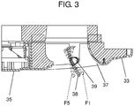
- FIG. 3 is a partial cross section of the indoor unit, which is used to explain an operation of the flaps.
- an exemplary room air conditioning system that will be described below is installed on a ceiling.
- the arrangement of constituent elements in the room air conditioning system will be described with reference to the "top”, “bottom”, and “side” in FIG. 1 .
- the room air conditioning system in this exemplary embodiment includes indoor unit 10 installed on ceiling 11 in a house, a building or other structures. As illustrated in FIG. 1 , indoor unit 10 is positioned in ceiling space 13 between ceiling 11 and ceiling plate 12 disposed under ceiling 11.
- Indoor unit 10 includes air conditioner main body 14, which has a lower surface 14a having an opening and is formed into a rectangular shape, for example. Air conditioner main body 14 is hung from ceiling 11 with hanging bolts 15.
- Thermal insulating member 16 which is made of Styrofoam (TM), for example, is disposed inside air conditioner main body 14. Thermal insulating member 16 is in contact with the inner surface of side plate 17 of air conditioner main body 14, thereby reducing condensation on side plate 17 of air conditioner main body 14.
- TM Styrofoam
- Fan motor 21 is mounted on the lower surface of upper plate 18 of air conditioner main body 14. Fan motor 21 extends downward and is provided with rotating shaft 22, which rotates in response to the driving of fan motor 21. The lower end of rotating shaft 22 is attached to centrifugal fan 23. Both fan motor 21 and centrifugal fan 23 constitute blower 20.
- Centrifugal fan 23 has main plate 24 having a flat, circular shape.
- Main plate 24 has motor container 25 on the lower surface at its center, motor container 25 having a frustum shape.
- Motor container 25 accommodates fan motor 21.
- Rotating shaft 22 of fan motor 21 extends downward with its lower end connected to bottom surface 25a of motor container 25. With the driving of fan motor 21, centrifugal fan 23 to which rotating shaft 22 is connected rotates.
- Main plate 24 is provided with shroud 26 having a lower circumferential surface formed into an arc shape, for example.
- a plurality of vanes 27 are disposed at predetermined spacings between main plate 24 and the inner circumferential surface of shroud 26.
- Orifice 28 is disposed below shroud 26.
- Orifice 28 is formed into a circular shape, and its circumference is formed into an arc shape, for example.
- Heat exchanger 30 is disposed between blower 20 and thermal insulating member 16. Heat exchanger 30 is formed into a substantially rectangular shape (including a rectangular shape) in a plan view by bending and folding process. Heat exchanger 30 surrounds all the sides of blower 20.
- heat exchanger 30 functions as an evaporator for a coolant.
- heat exchanger 30 functions as a radiator for the coolant.
- Heat exchanger 30 exchanges heat between the coolant and air sucked from the room into air conditioner main body 14.
- heat exchanger 30 cools the air inside the air conditioning room.
- heat exchanger 30 heats the air inside the room.
- Drain pan 31 is disposed below heat exchanger 30 so as to face lower surface 30a of heat exchanger 30. Drain pan 31 receives drain water from heat exchanger 30, thus preventing the drain water from dropping onto the floor. Drain pan 31 has central suction opening 32 through which blower 20 sucks air.
- decorative panel 33 that has a substantially rectangular shape (including a rectangular shape) is attached to the lower surface of air conditioner main body 14.
- Decorative panel 33 covers the opening in lower surface 14a of air conditioner main body 14.
- Decorative panel 33 has central suction opening 34 communicating with suction opening 32 in drain pan 31.
- Suction grill 35 is detachably attached to decorative panel 33 so as to cover suction opening 34.
- the surface of suction grill 35 which faces air conditioner main body 14 is provided with filter 36. Filter 36 captures dust or other foreign matter in air to be absorbed into air conditioner main body 14 through suction opening 34 in decorative panel 33.
- Decorative panel 33 has blow-off openings 37, through which air whose temperature has been adjusted by indoor unit 10 is supplied to the interior of the room.
- Blow-off openings 37 are positioned outside the rectangular suction opening 34 in decorative panel 33 and along the respective four sides of decorative panel 33.
- centrifugal fan 23 When centrifugal fan 23 is rotated by fan motor 21 through rotating shaft 22, air in the room is sucked into indoor unit 10 via both suction opening 34 in decorative panel 33 and suction opening 32 in drain pan 31. Then, dust and other foreign matter are removed from the air by filter 36.
- the air passes through heat exchanger 30 while being subjected to the heat exchange, so that the temperature of the air is adjusted.
- the resultant air is returned to the interior of the room through blow-off openings 37 in decorative panel 33, thereby adjusting the room temperature.
- flaps 38 are provided in respective blow-off openings 37 formed along the four sides of decorative panel 33.
- flaps 38 when the flaps are collectively indicated, the flaps are referred to as flaps 38, whereas when the flaps are individually indicated as opposing pairs of flaps, the flaps are referred to as flaps 38A and 38B.
- flaps 38 include the opposing pair of flaps 38A (for example, a first pair of flaps) and the opposing pair of flaps 38B (for example, a second pair of flaps), in which a direction in which flaps 38A face each other is orthogonal to that in which flaps 38B face each other.
- Each of flaps 38 has support shafts (not illustrated) at both longitudinal ends and is attached to both short sides of a corresponding blow-off opening 37 through the support shafts. Consequently, flaps 38 are supported so as to be rotatable around the support shafts.
- Hinge 39 is provided on the rear surface of each flap 38 which faces air conditioner main body 14, at substantially the middle (including the middle) in a longitudinal direction. Hinges 39 are driven by flap driving motor 40 (see FIG. 5 ). Flaps 38 thereby can rotate independently of one another by flap driving motor 40.
- the angle of each flap 38 can change in five stages ranging from first stage (F1) to fifth stage (F5), so that a direction of airflow from each blow-off opening 37 is adjusted.
- first stage (F1) the angle of flap 38 is set to the smallest value with respect to the horizontal plane, so that air flows horizontally.
- fifth stage (F5) the angle of flap 38 is set to the largest value, namely, approximately 90 degrees with respect to the horizontal surface, so that air blows directly downward.
- Second stage (F2), third stage (F3), and fourth stage (F4) correspond to midway stages in which the angle of flap 38 changes stepwise in the range from the smallest value to the largest value.
- floor temperature sensor 41 and human body sensor 42 are disposed in decorative panel 33 at one corner.
- Floor temperature sensor 41 detects a temperature of the floor in the room.
- Human body sensor 42 detects whether a person is present in the room or where a person is.
- FIG. 4 illustrates the placement of indoor units
- a plurality of indoor units 10 are installed on the ceiling in a single air conditioning room.
- indoor units 10A and 10B are installed.
- the indoor units are referred to as the indoor units 10
- the indoor units are referred to as indoor units 10A and 10B.
- each of indoor units 10A, 10B has single human body sensor 42.
- Human body sensor 42 disposed in indoor unit 10A detects whether a person is present within a predetermined region below indoor unit 10A
- human body sensor 42 disposed in indoor unit 10B detects whether a person is present within a predetermined region below indoor unit 10B.
- single human body sensor 42 is disposed in each of indoor units 10A and 10B. This configuration can detect whether a person is present within the region below each of indoor units 10A and 10B.
- FIG. 5 is a block diagram of a control configuration of the room air conditioning system.
- the room air conditioning system in this exemplary embodiment includes controller 45, which may be implemented using a central processing unit (CPU) and a memory, for example and operates in accordance with a predetermined program. Controller 45 controls operations of various units constituting a plurality of indoor units 10 to which controller 45 is connected. Examples of these units include fan motors 21, flap driving motors 40, floor temperature sensors 41, and human body sensors 42.
- CPU central processing unit
- memory for example and operates in accordance with a predetermined program.
- Controller 45 controls operations of various units constituting a plurality of indoor units 10 to which controller 45 is connected. Examples of these units include fan motors 21, flap driving motors 40, floor temperature sensors 41, and human body sensors 42.
- the room air conditioning system includes two indoor units 10A, 10B.
- Each of indoor units 10A, 10B includes: floor temperature sensor 41 that detects a temperature of the floor in the room; and human body sensor 42 that detects the presence of a person in the room.
- Floor temperature sensor 41 detects a temperature of the floor in the room, and human body sensor 42 detects the presence of a person in the room. Then, both floor temperature sensor 41 and human body sensor 42 transmit the detection results to controller 45. Controller 45 controls operations of fan motor 21 and flap driving motor 40 in each of indoor units 10A, 10B, based on the received detection results.
- controller 45 determines whether persons are present at the sites below and corresponding to indoor units 10A, 10B, based on the detection results from human body sensor 42.
- controller 45 can perform airflow control and temperature evenness control.
- the airflow control is performed such that air is not blown directly into a person in the room.
- the temperature evenness control is performed such that air circulates inside the room and thus reduces unevenness of room temperature. Both the airflow control and the temperature evenness control may be selected optionally by a user through an operation using remote controller 46, for example, disposed inside the room.
- controller 45 detects whether persons are present below indoor units 10 by using respective human body sensors 42. If detecting the presence of a person below one of indoor units 10 (indoor unit 10A in FIG. 4 ), controller 45 controls the angles of the flaps 38 in indoor unit 10A such that air is not blown directly into the detected person. More specifically, for example, controller 45 controls flaps 38 so as to blow air at an angle ranging from first stage (F1) to third stage (F3).
- controller 45 causes indoor unit 10B to perform the temperature evenness control.
- controller 45 causes indoor unit 10B to perform the temperature evenness control.
- the room air conditioning system successfully suppresses the person from being annoyed by airflow and reduces unevenness of the room temperature.
- FIG. 6A illustrates an operation of the flaps under temperature evenness control in the exemplary embodiment.
- the opposing pair of flaps 38B (for example, a first pair of flaps) rotates such that their angles are equal to that in fifth stage (F5)
- the opposing pair of flaps 38A (for example, a second pair of flaps) rotates such that their angles are equal to that in third stage (F3).
- indoor unit 10 blows air for a preset period (e.g., approximately 10 minutes).
- all flaps 38 rotate such that their angles are equal to that in fifth stage (F5).
- indoor unit 10 blows air for a preset period (e.g., approximately 10 minutes).
- the opposing pair of flaps 38B whose angles have been set to that in fifth stage (F5) in the first step rotates such that their angles are equal to that in third stage (F3).
- the opposing pair of flaps 38A whose angles have been set to that in third stage (F3) in the first step rotates such that their angles are equal to that in fifth stage (F5).
- indoor unit 10 blows air for a preset period (e.g., approximately 10 minutes).
- controller 45 sequentially performs the operations in the first step, the second step, and the third step. Then, controller 45 performs the above operations in the reverse sequence, that is, sequentially performs the operations in the third step, the second step, and the first step. In short, controller 45 performs the operation in the second step at which the angles of all flaps 38 are set to that in fifth stage (F5) between the operations in the first and third steps. Performing these sequential operations in this manner successfully reduces unevenness of room temperature.
- the angles of one pair of flaps 38 are set to that in fifth stage (F5), and the angles of the remaining pair of flaps 38 are set to that in third stage (F3); however, the angles of flaps 38 in the first and third steps are not limited.
- the angles in the first stage (F1) and the second stage (F2) out of the first stage (F1) to the fifth stage (F5) are set such that air is not blown directly into a person in the room.
- the angle in the third stage (F3) is used as an angle that is the smallest one of the angles at which air is blown directly into a person below indoor unit 10. Therefore, if an angle of each flap 38 is set in six or more stages, for example, the angles of one pair of flaps 38 may be set to that in fourth stage (F4) and the angles of the remaining pair of flaps 38 may be set to that in sixth stage (F6), in the first and third steps under the temperature evenness control.
- each flap 38 may be set in up to four stages, for example, the angles of one pair of flaps 38 may be set to that in second stage (F2) and the angles of the remaining pair of flaps 38 may be set to that in fourth stage (F4), in the first and third steps under the temperature evenness control.
- FIG. 6B illustrates another operation of the flaps under the temperature evenness control.
- an adjacent pair of flaps 38A, 38B rotates such that their angles are equal to that in fifth stage (F5), and the remaining adjacent pair of flaps 38A, 38B (for example, a second pair of flaps) rotates such that their angles are equal to that in third stage (F3).
- indoor unit 10 blows air for a preset period (e.g., approximately 10 minutes).
- all flaps 38 rotate such that their angles are equal to that in fifth stage (F5), similar to the example in FIG. 6A .
- indoor unit 10 blows air for a preset period (e.g., approximately 10 minutes).
- the adjacent pair of flaps 38A, 38B whose angles have been set to that in the fifth stage (F5) in the first step rotates such that their angles are equal to that in third stage (F3).
- the adjacent pair of flaps 38A, 38B whose angles have been set to that in the third stage (F3) in the first step rotates such that their angles are equal to that in fifth stage (F5).
- indoor unit 10 blows air for a preset period (e.g., approximately 10 minutes).
- controller 45 sequentially performs the operations in the first step, the second step, and the third step. Then, controller 45 performs the above operations in the reverse sequence, that is, sequentially performs the operations in the third step, the second step, and the first step. This successfully reduces unevenness of room temperature.
- flaps 38 may rotate such that their angles are equal to that in fourth stage (F4) or fifth stage (F5), for example, instead of that in third stage (F3).
- flaps 38 may continue to move between the location at which their angles are equal to that in first stage (F1) and the location at which their angles are equal to that in fifth stage (F5).
- flaps 38 may perform the so-called swing operation. This is also effective in reducing unevenness of room temperature.
- indoor units 10A, 10B are installed in the room as a plurality of indoor units 10, especially although indoor units 10 are not discriminated against each other.
- FIG. 7 is a flowchart of a control operation of the room air conditioning system when the indoor units perform a heating operation.
- controller 45 determines whether the airflow control is selected (Step ST1). If the airflow control is not selected (NO at Step ST1), controller 45 waits until the airflow control has been selected.
- Step ST1 human body sensors 42 of indoor units 10 detect whether persons are present below respective indoor units 10 (Step ST2). In this case, if human body sensor 42 in each indoor unit 10 detects the presence of a person (YES in Step ST2), controller 45 waits until human body sensor 42 detects the absence of the person.
- Step ST3 floor temperature sensor 41 in indoor unit 10 in which no person is present detects whether a temperature of the floor in the room is equal to or lower than a predetermined temperature (e.g., 18°C) (Step ST3). If the temperature of the floor in the room exceeds 18°C (NO in Step ST3), the control operation returns to Step ST2, and the room air conditioning system performs the operation at Step ST2 and the subsequent operations.
- a predetermined temperature e.g., 18°C
- controller 45 starts to perform the temperature evenness control (Step ST4).
- controller 45 In response to the start of the temperature evenness control, controller 45 starts to measure a time period (Step ST5). While the temperature evenness control is performed, controller 45 causes human body sensor 42 to detect whether a person is present below indoor unit 10 (Step ST6). For example, if someone enters the room and thus human body sensor 42 detects his/her presence (YES in Step ST6), controller 45 terminates the temperature evenness control quickly (Step ST8).
- controller 45 determines whether a predetermined period (e.g., 10 minutes) has elapsed from the start of the temperature evenness control (Step ST7). If 10 minutes have not yet elapsed (NO at Step ST7), the control operation returns to Step ST6, and the room air conditioning system performs the operation in Step ST6 and the subsequent operations.
- a predetermined period e.g. 10 minutes
- controller 45 terminates the temperature evenness control (Step ST8).
- Controller 45 determines whether the compressor in heat exchanger 30 is stopped, namely, whether the so-called thermo-off operation has been performed (Step ST9). If the thermo-off operation has not yet been performed (NO in Step ST9), controller 45 waits until the thermo-off operation has been performed.
- thermo-off operation If the thermo-off operation has already been performed (YES at Step ST9), the control operation returns to Step ST1, and the room air conditioning system continues to perform the operation in Step ST1 and the subsequent operations.
- control operation is performed during the heating operation.
- indoor units 10A, 10B are installed in the room as a plurality of indoor units 10, although indoor units 10 are not especially discriminated against each other.
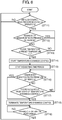
- FIG. 8 is a flowchart of a control operation of the room air conditioning system when the indoor units perform a cooling operation.
- controller 45 determines whether the airflow control is selected (Step ST11). If the airflow control is not selected (NO at Step ST11), controller 45 waits until the airflow control has been selected.
- Step ST11 human body sensors 42 of indoor units 10 detect whether persons are present below respective indoor units 10 (Step ST12). In this case, if human body sensor 42 in each indoor unit 10 detects the presence of a person (YES in Step ST12), controller 45 waits until human body sensor 42 detects the absence of the person.
- Step ST13 If one of human body sensors 42 in indoor units 10 does not detect the presence of a person (NO in Step ST12), floor temperature sensor 41 in indoor unit 10 in which no person is present detects a temperature of the floor in the room (Step ST13).
- controller 45 causes floor temperature sensor 41 to detect whether a temperature of the floor in the room is a predetermined temperature (e.g., a preset temperature + ⁇ ; ⁇ is in the range from approximately 2°C to approximately 3°C) (Step ST13). If the floor temperature is lower than the predetermined temperature (NO in Step ST13), the control operation returns to Step ST12, and the room air conditioning system performs the operation in Step ST12 and the subsequent operations.
- a predetermined temperature e.g., a preset temperature + ⁇ ; ⁇ is in the range from approximately 2°C to approximately 3°C
- controller 45 starts the temperature evenness control (Step ST14).
- controller 45 In response to the start of the temperature evenness control, controller 45 starts to measure a time period (Step ST15). While the temperature evenness control is performed, controller 45 causes human body sensor 42 to detect whether a person is present below indoor unit 10 (Step ST16). If detecting the presence of a person (YES in Step ST16), controller 45 terminates the temperature evenness control quickly (Step ST18).
- controller 45 determines whether a preset period (e.g., 10 minutes) has elapsed from the start of the temperature evenness control (Step ST17). If 10 minutes have not yet elapsed (NO at Step ST17), the control operation returns to Step ST16, and the room air conditioning system performs the operation in Step ST16 and the subsequent operations.
- a preset period e.g. 10 minutes
- controller 45 terminates the temperature evenness control (Step ST18).
- Controller 45 determines whether the compressor in heat exchanger 30 is stopped, namely, whether the so-called thermo-off operation has been performed (Step ST19). If the thermo-off operation has not yet been performed (NO at Step ST19), controller 45 waits until the thermo-off operation has been performed.
- thermo-off operation If the thermo-off operation has already been performed (YES in Step ST19), the control operation returns to Step ST11, and the room air conditioning system performs the operation in Step ST11 and the subsequent operations again.
- control operation is performed during the cooling operation.
- controller 45 terminates the temperature evenness control after a predetermined period has elapsed; however, the control operation is not limited to this example.
- controller 45 may detect a floor temperature by using floor temperature sensor 41, and may terminate the temperature evenness control if the floor temperature reaches a predetermined temperature (e.g., 26°C). This successfully reduces the risk that a user's body, especially around the foot may be overcooled during the cooling operation.
- indoor unit 10 in which no person is present performs the temperature evenness control; however, the control operation is not limited to this example.
- the above control operation may create following disadvantage. Specifically, for example, when indoor unit 10B does not detect the presence of a person as illustrated in FIG. 4 and thus performs the temperature evenness control, air from indoor unit 10B may be blown directly into a person present below adjacent indoor unit 10A.
- controller 45 may control indoor unit 10B to continuously blow air with the angle of flap 38 closest to indoor unit 10A kept unchanged (e.g., kept at the angle in first stage (F1) or second stage (F2)).
- controller 45 may control indoor unit 10B to perform the temperature evenness control with the angles of the remaining flaps 38 in the respective blow-off openings 37 changed in the above manner. This successfully reduces the risk of blowing air directly into a person below adjacent indoor unit 10A.
- controller 45 detects whether persons are present below respective indoor units 10 by using human body sensors 42, with the airflow control being selected. Then, if not detecting the presence of a person, indoor unit 10 in which no person is present performs the temperature evenness control. This successfully reduces the risk of blowing air directly into a person while reducing unevenness of room temperature.
- controller 45 when not detecting the presence of a person, performs a control operation, based on a temperature of the floor in the room which is detected by floor temperature sensor 41. More specifically, when the floor temperature is lower than a predetermined temperature (e.g., 28°C) during the heating operation or when the floor temperature is higher than another predetermined temperature (e.g., 25°C) during the cooling operation, indoor unit 10 that does not detect the presence of a person performs the temperature evenness control. In short, when a floor temperature is considerably different from a preset temperature, indoor unit 10 performs the temperature evenness control. This successfully reduces unevenness of room temperature efficiently.
- a predetermined temperature e.g. 28°C
- another predetermined temperature e.g. 25°C
- controller 45 terminates the temperature evenness control after a predetermined time period has elapsed from the start of the temperature evenness control. This successfully reduces the risk that controller 45 may excessively perform the temperature evenness control.
- controller 45 when detecting the presence of a person by using human body sensor 42 during the temperature evenness control, controller 45 terminates the temperature evenness control. This successfully reduces the risk of blowing air directly into a person.
- a room air conditioning system includes, inter alia: a plurality of indoor units to be installed on a ceiling; and a controller that causes the plurality of indoor units to perform airflow control and temperature evenness control.
- Each of the plurality of indoor units includes: an air conditioner main body; a plurality of flaps; and a human body sensor.
- a lower surface of the air conditioner main body has a periphery along which a plurality of blow-off openings are formed.
- the plurality of flaps are rotatably disposed in the respective blow-off openings and are capable of independently changing vertical angles of airflows.
- the human body sensor detects whether a person is present below a corresponding one of the plurality of indoor units.
- the controller When at least one of the human body sensors in the plurality of indoor units detects the absence of a person with the airflow control being selected, the controller causes a corresponding one of the indoor units which detects the absence to perform the temperature evenness control. In this way, the room air conditioning system can reduce the risk of blowing air directly into a person while reducing unevenness of room temperature.
- each of the plurality of indoor units preferably further includes a floor temperature sensor that detects a temperature of a floor in a room.
- a floor temperature sensor that detects a temperature of a floor in a room.
- the controller may terminate the temperature evenness control after a predetermined time period has elapsed from a start of the temperature evenness control. In this way, the room air conditioning system can reduce the risk that the controller may excessively perform the temperature evenness control, thereby operating efficiently.
- the controller may terminate the temperature evenness control. In this way, the room air conditioning system can reduce the risk of blowing air directly into a person.
- the plurality of flaps preferably include a first pair of flaps opposing each other and a second pair of flaps opposing each other, the first pair of flaps and the second pair of flaps being disposed perpendicularly to each other.
- the controller may perform the temperature evenness control by sequentially performing: a first step of positioning, of the plurality of flaps, the first pair of flaps at an angle of the lowest location and the second pair of flaps at an angle of a middle location; a second step of positioning all of the plurality of flaps at the angle of the lowest location; and a third step of positioning the first pair of flaps at the angle of the middle location and the second pair of flaps at the angle of the lowest location.
- the plurality of flaps preferably include a first pair of flaps disposed adjacent to each other and a second pair of flaps disposed adjacent to each other.
- the controller may perform the temperature evenness control by sequentially performing: a first step of positioning, of the first and second pairs, the first pair of flaps at an angle of the lowest location and the second pair of flaps at an angle of a middle location; a second step of positioning all of the plurality of flaps at the angle of the lowest location; and a third step of positioning the first pair of flaps at the angle of the middle location and the second pair of flaps at the angle of the lowest location.
- the room air conditioning system can reduce the risk of blowing air directly into a person while reducing unevenness of room temperature efficiently.
Landscapes
- Engineering & Computer Science (AREA)
- Chemical & Material Sciences (AREA)
- Combustion & Propulsion (AREA)
- Mechanical Engineering (AREA)
- General Engineering & Computer Science (AREA)
- Physics & Mathematics (AREA)
- Thermal Sciences (AREA)
- Air Conditioning Control Device (AREA)
Description
- The present invention relates to a room air conditioning system in an air conditioner, which includes at least four horizontal vanes (flaps) in blow-off openings and can independently change vertical angles of airflows.
- Unexamined
Japanese Patent Publication No. 2011-099609 Japanese Patent No. 5,310,792 - The first indoor unit disclosed in PTL1 includes a controller and a human body sensor. If the human body sensor detects the presence of a person when the indoor unit starts a heating operation, the controller controls the horizontal flap in the blow-off opening that corresponds to the target area in which the detected person is present. In this way, the controller suppresses air from being directly blown into the person.
- Similar to the controller in PTL1, human body sensors in the second indoor unit disclosed in PTL2 detect whether persons are present below the respective blow-off openings. If any of the human body sensors detects the presence of a person, the controller controls one of a plurality of vanes which corresponds to the target area in which the detected person is present such that air flows horizontally within this target area.
- The human body sensor in the first indoor unit in PTL 1 has a rotatable opening section, which rotates when the human body sensor detects whether persons are present within the respective target areas. The above second indoor unit has a human body sensor assembly made up of the human body sensors that detect whether persons are present within the respective target areas.
- Unfortunately, both the human body sensors in the first and second indoor units need to detect whether persons are present within as many as four target areas. In which case, the structure of the human body sensors may be complex and thus expensive.
- Moreover,
JP patent application 2015-21719 - The present invention provides a room air conditioning system as defined in claims 1 and 5, which is capable of reducing unevenness of room temperature without directly blowing air into a person.
- The room air conditioning system according to claims 1 and 5 includes, amongst others: a plurality of indoor units to be installed on a ceiling; and a controller that causes the plurality of indoor units to perform airflow control and temperature evenness control. Each of the plurality of indoor units includes: an air conditioner main body; a plurality of flaps; and a human body sensor. A lower surface of the air conditioner main body has a periphery along which a plurality of blow-off openings are formed. The plurality of flaps are rotatably disposed in the respective blow-off openings and are capable of independently changing vertical angles of airflows. The human body sensor detects whether a person is present below a corresponding one of the plurality of indoor units. When at least one of the human body sensors in the plurality of indoor units detects the absence of a person with the airflow control being selected, the controller causes a corresponding one of the indoor units that detects the absence to perform the temperature evenness control.
- According to the above configuration, when at least one of the human body sensors in the plurality of indoor units detects the absence of a person with the airflow control being selected, the controller causes a corresponding one of the indoor units that detects the absence to perform the temperature evenness control. In this way, the room air conditioning system can reduce unevenness of room temperature without blowing air directly into a person.
-
-
FIG. 1 illustrates a vertical cross section of an exemplary indoor unit in a room air conditioning system according to an exemplary embodiment of the present invention; -
FIG. 2 is a plan view of the indoor unit as seen from the floor in a room; -
FIG. 3 is a partial cross section of the indoor unit, which is used to explain an operation of the flaps; -
FIG. 4 illustrates the placement of indoor units; -
FIG. 5 is a block diagram of a control configuration of the room air conditioning system; -
FIG. 6A illustrates an operation of the flaps under temperature evenness control according to the exemplary embodiment; -
FIG. 6B illustrates another operation of the flaps under the temperature evenness control; -
FIG. 7 is a flowchart of a control operation of the room air conditioning system when indoor units perform a heating operation; and -
FIG. 8 is a flowchart of a control operation of the room air conditioning system when the indoor units perform a cooling operation. - A description will be given below of a room air conditioning system according to some exemplary embodiments of the present invention, with reference to the accompanying drawings.
-
FIG. 1 illustrates a vertical cross section of an exemplary indoor unit in a room air conditioning system according to an exemplary embodiment of the present invention.FIG. 2 is a plan view of a decorative panel in the indoor unit as seen from the floor in a room.FIG. 3 is a partial cross section of the indoor unit, which is used to explain an operation of the flaps. - Herein, an exemplary room air conditioning system that will be described below is installed on a ceiling. The arrangement of constituent elements in the room air conditioning system will be described with reference to the "top", "bottom", and "side" in
FIG. 1 . - The room air conditioning system in this exemplary embodiment includes
indoor unit 10 installed onceiling 11 in a house, a building or other structures. As illustrated inFIG. 1 ,indoor unit 10 is positioned inceiling space 13 betweenceiling 11 andceiling plate 12 disposed underceiling 11. -
Indoor unit 10 includes air conditionermain body 14, which has alower surface 14a having an opening and is formed into a rectangular shape, for example. Air conditionermain body 14 is hung fromceiling 11 with hangingbolts 15. -
Thermal insulating member 16, which is made of Styrofoam (TM), for example, is disposed inside air conditionermain body 14.Thermal insulating member 16 is in contact with the inner surface ofside plate 17 of air conditionermain body 14, thereby reducing condensation onside plate 17 of air conditionermain body 14. -
Fan motor 21 is mounted on the lower surface ofupper plate 18 of air conditionermain body 14.Fan motor 21 extends downward and is provided with rotatingshaft 22, which rotates in response to the driving offan motor 21. The lower end of rotatingshaft 22 is attached tocentrifugal fan 23. Bothfan motor 21 andcentrifugal fan 23 constituteblower 20. -
Centrifugal fan 23 hasmain plate 24 having a flat, circular shape.Main plate 24 hasmotor container 25 on the lower surface at its center,motor container 25 having a frustum shape. -
Motor container 25 accommodatesfan motor 21. Rotatingshaft 22 offan motor 21 extends downward with its lower end connected tobottom surface 25a ofmotor container 25. With the driving offan motor 21,centrifugal fan 23 to which rotatingshaft 22 is connected rotates. -
Main plate 24 is provided withshroud 26 having a lower circumferential surface formed into an arc shape, for example. A plurality ofvanes 27 are disposed at predetermined spacings betweenmain plate 24 and the inner circumferential surface ofshroud 26. -
Orifice 28 is disposed belowshroud 26.Orifice 28 is formed into a circular shape, and its circumference is formed into an arc shape, for example. -
Heat exchanger 30 is disposed betweenblower 20 and thermal insulatingmember 16.Heat exchanger 30 is formed into a substantially rectangular shape (including a rectangular shape) in a plan view by bending and folding process.Heat exchanger 30 surrounds all the sides ofblower 20. - During a cooling operation,
heat exchanger 30 functions as an evaporator for a coolant. During a heating operation,heat exchanger 30 functions as a radiator for the coolant.Heat exchanger 30 exchanges heat between the coolant and air sucked from the room into air conditionermain body 14. During the cooling operation,heat exchanger 30 cools the air inside the air conditioning room. During the heating operation,heat exchanger 30 heats the air inside the room. -
Drain pan 31 is disposed belowheat exchanger 30 so as to facelower surface 30a ofheat exchanger 30.Drain pan 31 receives drain water fromheat exchanger 30, thus preventing the drain water from dropping onto the floor.Drain pan 31 hascentral suction opening 32 through whichblower 20 sucks air. - As illustrated in
FIG. 1 andFIG. 2 ,decorative panel 33 that has a substantially rectangular shape (including a rectangular shape) is attached to the lower surface of air conditionermain body 14.Decorative panel 33 covers the opening inlower surface 14a of air conditionermain body 14. -
Decorative panel 33 hascentral suction opening 34 communicating with suction opening 32 indrain pan 31.Suction grill 35 is detachably attached todecorative panel 33 so as to coversuction opening 34. The surface ofsuction grill 35 which faces air conditionermain body 14 is provided withfilter 36.Filter 36 captures dust or other foreign matter in air to be absorbed into air conditionermain body 14 through suction opening 34 indecorative panel 33. -
Decorative panel 33 has blow-offopenings 37, through which air whose temperature has been adjusted byindoor unit 10 is supplied to the interior of the room. Blow-offopenings 37 are positioned outside the rectangular suction opening 34 indecorative panel 33 and along the respective four sides ofdecorative panel 33. Whencentrifugal fan 23 is rotated byfan motor 21 throughrotating shaft 22, air in the room is sucked intoindoor unit 10 via bothsuction opening 34 indecorative panel 33 andsuction opening 32 indrain pan 31. Then, dust and other foreign matter are removed from the air byfilter 36. After having enteredindoor unit 10, the air passes throughheat exchanger 30 while being subjected to the heat exchange, so that the temperature of the air is adjusted. The resultant air is returned to the interior of the room through blow-offopenings 37 indecorative panel 33, thereby adjusting the room temperature. - As illustrated in
FIG. 2 andFIG. 3 , flaps 38, each of which can change a direction of airflow, are provided in respective blow-offopenings 37 formed along the four sides ofdecorative panel 33. Hereinafter, when the flaps are collectively indicated, the flaps are referred to asflaps 38, whereas when the flaps are individually indicated as opposing pairs of flaps, the flaps are referred to asflaps - In this exemplary embodiment, flaps 38 include the opposing pair of
flaps 38A (for example, a first pair of flaps) and the opposing pair offlaps 38B (for example, a second pair of flaps), in which a direction in which flaps 38A face each other is orthogonal to that in which flaps 38B face each other. Each offlaps 38 has support shafts (not illustrated) at both longitudinal ends and is attached to both short sides of a corresponding blow-off opening 37 through the support shafts. Consequently, flaps 38 are supported so as to be rotatable around the support shafts.Hinge 39 is provided on the rear surface of eachflap 38 which faces air conditionermain body 14, at substantially the middle (including the middle) in a longitudinal direction.Hinges 39 are driven by flap driving motor 40 (seeFIG. 5 ).Flaps 38 thereby can rotate independently of one another byflap driving motor 40. - In this exemplary embodiment, as illustrated in
FIG. 3 , the angle of eachflap 38 can change in five stages ranging from first stage (F1) to fifth stage (F5), so that a direction of airflow from each blow-off opening 37 is adjusted. In first stage (F1), the angle offlap 38 is set to the smallest value with respect to the horizontal plane, so that air flows horizontally. In fifth stage (F5), the angle offlap 38 is set to the largest value, namely, approximately 90 degrees with respect to the horizontal surface, so that air blows directly downward. Second stage (F2), third stage (F3), and fourth stage (F4) correspond to midway stages in which the angle offlap 38 changes stepwise in the range from the smallest value to the largest value. - As illustrated in
FIG. 2 ,floor temperature sensor 41 andhuman body sensor 42 are disposed indecorative panel 33 at one corner.Floor temperature sensor 41 detects a temperature of the floor in the room.Human body sensor 42 detects whether a person is present in the room or where a person is. - Up to this point, the configuration of the room air conditioning system in this exemplary embodiment has been described.
- Next, a description will be given below of a concrete example of placement of the room air conditioning system in this exemplary embodiment inside a room, with reference to
FIG. 4 . -
FIG. 4 illustrates the placement of indoor units; - In a typical case, a plurality of
indoor units 10 are installed on the ceiling in a single air conditioning room. - In this exemplary embodiment, as illustrated in
FIG. 4 ,indoor units indoor units 10, whereas when the indoor units are individually indicated, the indoor units are referred to asindoor units - As illustrated in
FIG. 4 , each ofindoor units human body sensor 42.Human body sensor 42 disposed inindoor unit 10A detects whether a person is present within a predetermined region belowindoor unit 10A, andhuman body sensor 42 disposed inindoor unit 10B detects whether a person is present within a predetermined region belowindoor unit 10B. - In this exemplary embodiment, single
human body sensor 42 is disposed in each ofindoor units indoor units - Next, a description will be given below of a control configuration of the room air conditioning system in this exemplary embodiment, with reference to
FIG. 5 . -
FIG. 5 is a block diagram of a control configuration of the room air conditioning system. - The room air conditioning system in this exemplary embodiment includes
controller 45, which may be implemented using a central processing unit (CPU) and a memory, for example and operates in accordance with a predetermined program.Controller 45 controls operations of various units constituting a plurality ofindoor units 10 to whichcontroller 45 is connected. Examples of these units includefan motors 21,flap driving motors 40,floor temperature sensors 41, andhuman body sensors 42. - Hereinafter, the room air conditioning system includes two
indoor units - Each of
indoor units floor temperature sensor 41 that detects a temperature of the floor in the room; andhuman body sensor 42 that detects the presence of a person in the room. -
Floor temperature sensor 41 detects a temperature of the floor in the room, andhuman body sensor 42 detects the presence of a person in the room. Then, bothfloor temperature sensor 41 andhuman body sensor 42 transmit the detection results tocontroller 45.Controller 45 controls operations offan motor 21 andflap driving motor 40 in each ofindoor units - Likewise,
controller 45 determines whether persons are present at the sites below and corresponding toindoor units human body sensor 42. - In the room air conditioning system in this exemplary embodiment,
controller 45 can perform airflow control and temperature evenness control. The airflow control is performed such that air is not blown directly into a person in the room. The temperature evenness control is performed such that air circulates inside the room and thus reduces unevenness of room temperature. Both the airflow control and the temperature evenness control may be selected optionally by a user through an operation usingremote controller 46, for example, disposed inside the room. - A description will be given below of an operation of the room air conditioning system when the user selects the airflow control by using
remote controller 46. - When the user selects the airflow control,
controller 45 detects whether persons are present belowindoor units 10 by using respectivehuman body sensors 42. If detecting the presence of a person below one of indoor units 10 (indoor unit 10A inFIG. 4 ),controller 45 controls the angles of theflaps 38 inindoor unit 10A such that air is not blown directly into the detected person. More specifically, for example,controller 45 controls flaps 38 so as to blow air at an angle ranging from first stage (F1) to third stage (F3). - Even when the airflow control is selected, if
human body sensor 42 does not detect the presence of a person below another one of indoor units 10 (indoor unit 10B inFIG. 4 ),controller 45 causesindoor unit 10B to perform the temperature evenness control. - More specifically, as illustrated in
FIG. 4 , whenhuman body sensor 42 inindoor unit 10A installed on the right side detects the presence of a person andhuman body sensor 42 inindoor unit 10B inindoor unit 10B installed on the left side does not detect the presence of a person,controller 45 causesindoor unit 10B to perform the temperature evenness control. In this way, the room air conditioning system successfully suppresses the person from being annoyed by airflow and reduces unevenness of the room temperature. - A description will be given below of an exemplary operation performed by the room air conditioning system in this exemplary embodiment under the temperature evenness control, with reference to
FIG. 6A . -
FIG. 6A illustrates an operation of the flaps under temperature evenness control in the exemplary embodiment. - Under the temperature evenness control, as illustrated in
FIG. 6A , operations from a first step to a third step are performed in accordance with the angles offlaps 38. - More specifically, in the first step, the opposing pair of
flaps 38B (for example, a first pair of flaps) rotates such that their angles are equal to that in fifth stage (F5), and the opposing pair offlaps 38A (for example, a second pair of flaps) rotates such that their angles are equal to that in third stage (F3). Then,indoor unit 10 blows air for a preset period (e.g., approximately 10 minutes). In the second step, all flaps 38 rotate such that their angles are equal to that in fifth stage (F5). Then,indoor unit 10 blows air for a preset period (e.g., approximately 10 minutes). At the third step, the opposing pair offlaps 38B whose angles have been set to that in fifth stage (F5) in the first step rotates such that their angles are equal to that in third stage (F3). Simultaneously, the opposing pair offlaps 38A whose angles have been set to that in third stage (F3) in the first step rotates such that their angles are equal to that in fifth stage (F5). Then,indoor unit 10 blows air for a preset period (e.g., approximately 10 minutes). - In this exemplary embodiment, first,
controller 45 sequentially performs the operations in the first step, the second step, and the third step. Then,controller 45 performs the above operations in the reverse sequence, that is, sequentially performs the operations in the third step, the second step, and the first step. In short,controller 45 performs the operation in the second step at which the angles of allflaps 38 are set to that in fifth stage (F5) between the operations in the first and third steps. Performing these sequential operations in this manner successfully reduces unevenness of room temperature. - In this exemplary embodiment, in both of the first step and the third step, the angles of one pair of
flaps 38 are set to that in fifth stage (F5), and the angles of the remaining pair offlaps 38 are set to that in third stage (F3); however, the angles offlaps 38 in the first and third steps are not limited. - In this exemplary embodiment, the angles in the first stage (F1) and the second stage (F2) out of the first stage (F1) to the fifth stage (F5) are set such that air is not blown directly into a person in the room. In addition, under the temperature evenness control, the angle in the third stage (F3) is used as an angle that is the smallest one of the angles at which air is blown directly into a person below
indoor unit 10. Therefore, if an angle of eachflap 38 is set in six or more stages, for example, the angles of one pair offlaps 38 may be set to that in fourth stage (F4) and the angles of the remaining pair offlaps 38 may be set to that in sixth stage (F6), in the first and third steps under the temperature evenness control. Alternatively, if an angle of eachflap 38 is set in up to four stages, for example, the angles of one pair offlaps 38 may be set to that in second stage (F2) and the angles of the remaining pair offlaps 38 may be set to that in fourth stage (F4), in the first and third steps under the temperature evenness control. - Next, a description will be given below of another exemplary operation performed by the room air conditioning system in this exemplary embodiment under the temperature evenness control, with reference to
FIG. 6B . -
FIG. 6B illustrates another operation of the flaps under the temperature evenness control. - Under the temperature evenness control, as illustrated in
FIG. 6B , operations from a first step to a third step are performed in accordance with the angles offlaps 38, similar to the example inFIG. 6A . - More specifically, as illustrated in
FIG. 6B , in the first step, an adjacent pair offlaps flaps indoor unit 10 blows air for a preset period (e.g., approximately 10 minutes). In the second step, all flaps 38 rotate such that their angles are equal to that in fifth stage (F5), similar to the example inFIG. 6A . Then,indoor unit 10 blows air for a preset period (e.g., approximately 10 minutes). In the third step, the adjacent pair offlaps flaps indoor unit 10 blows air for a preset period (e.g., approximately 10 minutes). - Similar to the example in
FIG. 6A , first,controller 45 sequentially performs the operations in the first step, the second step, and the third step. Then,controller 45 performs the above operations in the reverse sequence, that is, sequentially performs the operations in the third step, the second step, and the first step. This successfully reduces unevenness of room temperature. - When
indoor unit 10 blows air downward under the temperature evenness control in this exemplary embodiment, flaps 38 may rotate such that their angles are equal to that in fourth stage (F4) or fifth stage (F5), for example, instead of that in third stage (F3). Alternatively, flaps 38 may continue to move between the location at which their angles are equal to that in first stage (F1) and the location at which their angles are equal to that in fifth stage (F5). In short, flaps 38 may perform the so-called swing operation. This is also effective in reducing unevenness of room temperature. - Up to this point, the operation performed by the room air conditioning system in this exemplary embodiment under the temperature evenness control has been described.
- Next, a description will be given below of a control operation of the room air conditioning system in this exemplary embodiment.
- First, a description will be given below of a control operation of the room air conditioning system when
indoor units 10 perform a heating operation, with reference toFIG. 7 . In this case, for example,indoor units indoor units 10, especially althoughindoor units 10 are not discriminated against each other. -
FIG. 7 is a flowchart of a control operation of the room air conditioning system when the indoor units perform a heating operation. - As illustrated in
FIG. 7 , when eachindoor unit 10 performs a heating operation,controller 45 determines whether the airflow control is selected (Step ST1). If the airflow control is not selected (NO at Step ST1),controller 45 waits until the airflow control has been selected. - If the airflow control is selected, namely, the ON operation is performed (YES in Step ST1),
human body sensors 42 ofindoor units 10 detect whether persons are present below respective indoor units 10 (Step ST2). In this case, ifhuman body sensor 42 in eachindoor unit 10 detects the presence of a person (YES in Step ST2),controller 45 waits untilhuman body sensor 42 detects the absence of the person. - If one of
human body sensors 42 inindoor units 10 does not detect the presence of a person (NO in Step ST2),floor temperature sensor 41 inindoor unit 10 in which no person is present detects whether a temperature of the floor in the room is equal to or lower than a predetermined temperature (e.g., 18°C) (Step ST3). If the temperature of the floor in the room exceeds 18°C (NO in Step ST3), the control operation returns to Step ST2, and the room air conditioning system performs the operation at Step ST2 and the subsequent operations. - If
floor temperature sensor 41 detects that the temperature of the floor in the room is equal to or lower than 18°C (YES in Step ST3),controller 45 starts to perform the temperature evenness control (Step ST4). - In response to the start of the temperature evenness control,
controller 45 starts to measure a time period (Step ST5). While the temperature evenness control is performed,controller 45 causeshuman body sensor 42 to detect whether a person is present below indoor unit 10 (Step ST6). For example, if someone enters the room and thushuman body sensor 42 detects his/her presence (YES in Step ST6),controller 45 terminates the temperature evenness control quickly (Step ST8). - If
human body sensors 42 does not detect the presence of a person (NO in Step ST6),controller 45 determines whether a predetermined period (e.g., 10 minutes) has elapsed from the start of the temperature evenness control (Step ST7). If 10 minutes have not yet elapsed (NO at Step ST7), the control operation returns to Step ST6, and the room air conditioning system performs the operation in Step ST6 and the subsequent operations. - If 10 minutes have already elapsed (YES in Step ST7),
controller 45 terminates the temperature evenness control (Step ST8). -
Controller 45 determines whether the compressor inheat exchanger 30 is stopped, namely, whether the so-called thermo-off operation has been performed (Step ST9). If the thermo-off operation has not yet been performed (NO in Step ST9),controller 45 waits until the thermo-off operation has been performed. - If the thermo-off operation has already been performed (YES at Step ST9), the control operation returns to Step ST1, and the room air conditioning system continues to perform the operation in Step ST1 and the subsequent operations.
- In this way, the control operation is performed during the heating operation.
- Next, a description will be given below of a control operation of the room air conditioning system when
indoor units 10 perform a cooling operation, with reference toFIG. 8 . In this case, for example,indoor units indoor units 10, althoughindoor units 10 are not especially discriminated against each other. -
FIG. 8 is a flowchart of a control operation of the room air conditioning system when the indoor units perform a cooling operation. - As illustrated in
FIG. 8 , whenindoor units 10 perform a cooling operation,controller 45 determines whether the airflow control is selected (Step ST11). If the airflow control is not selected (NO at Step ST11),controller 45 waits until the airflow control has been selected. - If the airflow control, or an ON operation, is selected (YES in Step ST11),
human body sensors 42 ofindoor units 10 detect whether persons are present below respective indoor units 10 (Step ST12). In this case, ifhuman body sensor 42 in eachindoor unit 10 detects the presence of a person (YES in Step ST12),controller 45 waits untilhuman body sensor 42 detects the absence of the person. - If one of
human body sensors 42 inindoor units 10 does not detect the presence of a person (NO in Step ST12),floor temperature sensor 41 inindoor unit 10 in which no person is present detects a temperature of the floor in the room (Step ST13). - More specifically,
controller 45 causesfloor temperature sensor 41 to detect whether a temperature of the floor in the room is a predetermined temperature (e.g., a preset temperature + α; α is in the range from approximately 2°C to approximately 3°C) (Step ST13). If the floor temperature is lower than the predetermined temperature (NO in Step ST13), the control operation returns to Step ST12, and the room air conditioning system performs the operation in Step ST12 and the subsequent operations. - If
floor temperature sensor 41 detects that the floor temperature is equal to or higher than the predetermined temperature (YES in Step ST13),controller 45 starts the temperature evenness control (Step ST14). - In response to the start of the temperature evenness control,
controller 45 starts to measure a time period (Step ST15). While the temperature evenness control is performed,controller 45 causeshuman body sensor 42 to detect whether a person is present below indoor unit 10 (Step ST16). If detecting the presence of a person (YES in Step ST16),controller 45 terminates the temperature evenness control quickly (Step ST18). - If
human body sensor 42 does not detect the presence of a person (NO in Step ST16),controller 45 determines whether a preset period (e.g., 10 minutes) has elapsed from the start of the temperature evenness control (Step ST17). If 10 minutes have not yet elapsed (NO at Step ST17), the control operation returns to Step ST16, and the room air conditioning system performs the operation in Step ST16 and the subsequent operations. - If 10 minutes have already elapsed (YES at Step ST17),
controller 45 terminates the temperature evenness control (Step ST18). -
Controller 45 determines whether the compressor inheat exchanger 30 is stopped, namely, whether the so-called thermo-off operation has been performed (Step ST19). If the thermo-off operation has not yet been performed (NO at Step ST19),controller 45 waits until the thermo-off operation has been performed. - If the thermo-off operation has already been performed (YES in Step ST19), the control operation returns to Step ST11, and the room air conditioning system performs the operation in Step ST11 and the subsequent operations again.
- In this way, the control operation is performed during the cooling operation.
- In the foregoing exemplary embodiment,
controller 45 terminates the temperature evenness control after a predetermined period has elapsed; however, the control operation is not limited to this example. Alternatively, for example,controller 45 may detect a floor temperature by usingfloor temperature sensor 41, and may terminate the temperature evenness control if the floor temperature reaches a predetermined temperature (e.g., 26°C). This successfully reduces the risk that a user's body, especially around the foot may be overcooled during the cooling operation. - In this exemplary embodiment, when
human body sensor 42 does not detect the presence of a person,indoor unit 10 in which no person is present performs the temperature evenness control; however, the control operation is not limited to this example. For example, ifindoor units 10 are installed adjacent to each other and oneindoor unit 10 does not detect the presence of a person, the above control operation may create following disadvantage. Specifically, for example, whenindoor unit 10B does not detect the presence of a person as illustrated inFIG. 4 and thus performs the temperature evenness control, air fromindoor unit 10B may be blown directly into a person present below adjacentindoor unit 10A. - To reduce the risk of the above disadvantage occurring,
controller 45 may controlindoor unit 10B to continuously blow air with the angle offlap 38 closest toindoor unit 10A kept unchanged (e.g., kept at the angle in first stage (F1) or second stage (F2)). In addition,controller 45 may controlindoor unit 10B to perform the temperature evenness control with the angles of the remainingflaps 38 in the respective blow-offopenings 37 changed in the above manner. This successfully reduces the risk of blowing air directly into a person below adjacentindoor unit 10A. - In this exemplary embodiment, as described above,
controller 45 detects whether persons are present below respectiveindoor units 10 by usinghuman body sensors 42, with the airflow control being selected. Then, if not detecting the presence of a person,indoor unit 10 in which no person is present performs the temperature evenness control. This successfully reduces the risk of blowing air directly into a person while reducing unevenness of room temperature. - In this exemplary embodiment, when not detecting the presence of a person,
controller 45 performs a control operation, based on a temperature of the floor in the room which is detected byfloor temperature sensor 41. More specifically, when the floor temperature is lower than a predetermined temperature (e.g., 28°C) during the heating operation or when the floor temperature is higher than another predetermined temperature (e.g., 25°C) during the cooling operation,indoor unit 10 that does not detect the presence of a person performs the temperature evenness control. In short, when a floor temperature is considerably different from a preset temperature,indoor unit 10 performs the temperature evenness control. This successfully reduces unevenness of room temperature efficiently. - In this exemplary embodiment,
controller 45 terminates the temperature evenness control after a predetermined time period has elapsed from the start of the temperature evenness control. This successfully reduces the risk thatcontroller 45 may excessively perform the temperature evenness control. - In this exemplary embodiment, when detecting the presence of a person by using
human body sensor 42 during the temperature evenness control,controller 45 terminates the temperature evenness control. This successfully reduces the risk of blowing air directly into a person. - Up to this point, the exemplary embodiment of the present invention has been described with reference to the accompanying drawings. However, the present invention is not limited to this exemplary embodiment, and the exemplary embodiment can undergo various modifications without departing from the spirit of the invention.
- A room air conditioning system, as described above, according to an exemplary embodiment of the present invention includes, inter alia: a plurality of indoor units to be installed on a ceiling; and a controller that causes the plurality of indoor units to perform airflow control and temperature evenness control. Each of the plurality of indoor units includes: an air conditioner main body; a plurality of flaps; and a human body sensor. A lower surface of the air conditioner main body has a periphery along which a plurality of blow-off openings are formed. The plurality of flaps are rotatably disposed in the respective blow-off openings and are capable of independently changing vertical angles of airflows. The human body sensor detects whether a person is present below a corresponding one of the plurality of indoor units. When at least one of the human body sensors in the plurality of indoor units detects the absence of a person with the airflow control being selected, the controller causes a corresponding one of the indoor units which detects the absence to perform the temperature evenness control. In this way, the room air conditioning system can reduce the risk of blowing air directly into a person while reducing unevenness of room temperature.
- In the foregoing room air conditioning system, each of the plurality of indoor units preferably further includes a floor temperature sensor that detects a temperature of a floor in a room. When the absence of a person is detected and at least one of the floor temperature sensors detects a state that the temperature of the floor in the room is lower than a predetermined temperature during a heating operation or higher than a predetermined temperature during a cooling operation, the controller causes a corresponding one of the indoor units that detects the state to perform the temperature evenness control. In this way, the room air conditioning system can reduce unevenness of room temperature efficiently.
- In the foregoing room air conditioning system, the controller may terminate the temperature evenness control after a predetermined time period has elapsed from a start of the temperature evenness control. In this way, the room air conditioning system can reduce the risk that the controller may excessively perform the temperature evenness control, thereby operating efficiently.
- In the foregoing room air conditioning system, when the human body sensor of the indoor unit performing the temperature evenness control detects the presence of a person, the controller may terminate the temperature evenness control. In this way, the room air conditioning system can reduce the risk of blowing air directly into a person.
- In the foregoing room air conditioning system, the plurality of flaps preferably include a first pair of flaps opposing each other and a second pair of flaps opposing each other, the first pair of flaps and the second pair of flaps being disposed perpendicularly to each other.
- In the room air conditioning system, the controller may perform the temperature evenness control by sequentially performing: a first step of positioning, of the plurality of flaps, the first pair of flaps at an angle of the lowest location and the second pair of flaps at an angle of a middle location; a second step of positioning all of the plurality of flaps at the angle of the lowest location; and a third step of positioning the first pair of flaps at the angle of the middle location and the second pair of flaps at the angle of the lowest location.
- In the room air conditioning system, the plurality of flaps preferably include a first pair of flaps disposed adjacent to each other and a second pair of flaps disposed adjacent to each other. The controller may perform the temperature evenness control by sequentially performing: a first step of positioning, of the first and second pairs, the first pair of flaps at an angle of the lowest location and the second pair of flaps at an angle of a middle location; a second step of positioning all of the plurality of flaps at the angle of the lowest location; and a third step of positioning the first pair of flaps at the angle of the middle location and the second pair of flaps at the angle of the lowest location.
- In the above ways, the room air conditioning system can reduce the risk of blowing air directly into a person while reducing unevenness of room temperature efficiently.
Claims (5)
- A room air conditioning system, comprising:a plurality of indoor units (10, 10A, 10B) to be installed on a ceiling (11); anda controller (45) that causes the plurality of indoor units (10, 10A, 10B) to perform airflow control and temperature evenness control (ST4, ST7, ST8, ST14, ST17, ST18),wherein each of the plurality of indoor units (10, 10A, 10B) includes:an air conditioner main body (14) whose lower surface (14a, 30a) has a periphery along which a plurality of blow-off openings (37) are formed;a plurality of flaps (38, 38A, 38B) rotatably disposed in the respective blow-off openings (37), the flaps (38, 38A, 38B) being capable of independently changing vertical angles of airflows; anda human body sensor (42) that detects whether a person is present below a corresponding one of the plurality of indoor units (10, 10A, 10B),wherein when at least one of the human body sensors (42) in the plurality of indoor units (10, 10A, 10B) detects absence of a person with the airflow control being selected, the controller (45) causes a corresponding one of the indoor units (10, 10A, 10B) that detects the absence to perform the temperature evenness control (ST4, ST7, ST8, ST14, ST17, ST18), characterized in that the plurality of flaps (38, 38A, 38B) include a first pair of flaps (38A) opposing each other and a second pair of flaps (38B) opposing each other, the first pair of flaps (38A) and the second pair of flaps (38B) being disposed perpendicularly to each other, and in that the controller (45) is configured to perform the temperature evenness control (ST4, ST7, ST8, SST14, ST17, ST18) by sequentially performing:a first step of positioning, of the plurality of flaps (38, 38A, 38B), the first pair of flaps (38A) at an angle of a lowest location and the second pair of flaps (38B) at an angle of a middle location;a second step of positioning all of the plurality of flaps (38, 38A, 38B) at the angle of the lowest location; anda third step of positioning the first pair of flaps (38A) at the angle of the middle location and the second pair of flaps (38B) at the angle of the lowest location.
- The room air conditioning system according to claim 1, whereineach of the plurality of indoor units (10, 10A, 10B) further includes a floor temperature sensor (41) that detects a temperature of a floor in a room, andwhen absence of a person is detected and at least one of the floor temperature sensors (41) detects a state that the temperature of the floor in the room is lower than a predetermined temperature during a heating operation or higher than a predetermined temperature during a cooling operation, the controller (45) causes a corresponding one of the indoor units (10, 10A, 10B) that detects the state to perform the temperature evenness control (ST4, ST7, ST8, ST14, ST17, ST18).
- The room air conditioning system according to claim 1, wherein
the controller (45) terminates the temperature evenness control (ST4, ST7, ST8, ST14, ST17, ST18) after a predetermined time period has elapsed from a start of the temperature evenness control (ST4, ST7, ST8, ST14, ST17, ST18). - The room air conditioning system according to claim 1, wherein
when the human body sensor (42) of the indoor unit performing the temperature evenness control (ST4, ST7, ST8, ST14, ST17, ST18) detects presence of a person, the controller (45) terminates the temperature evenness control (ST4, ST7, ST8, ST14, ST17, ST18). - A room air conditioning system, comprising:a plurality of indoor units (10, 10A, 10B) to be installed on a ceiling (11); anda controller (45) that causes the plurality of indoor units (10, 10A, 10B) to perform airflow control and temperature evenness control (ST4, ST7, ST8, ST14, ST17, ST18),wherein each of the plurality of indoor units (10, 10A, 10B) includes:an air conditioner main body (14) whose lower surface (14a, 30a) has a periphery along which a plurality of blow-off openings (37) are formed;a plurality of flaps (38, 38A, 38B) rotatably disposed in the respective blow-off openings (37), the flaps (38, 38A, 38B) being capable of independently changing vertical angles of airflows; anda human body sensor (42) that detects whether a person is present below a corresponding one of the plurality of indoor units (10, 10A, 10B),wherein when at least one of the human body sensors (42) in the plurality of indoor units (10, 10A, 10B) detects absence of a person with the airflow control being selected, the controller (45) causes a corresponding one of the indoor units (10, 10A, 10B) that detects the absence to perform the temperature evenness control (ST4, ST7, ST8, ST14, ST17, ST18), characterized in that the plurality of flaps (38, 38A, 38B) include a first pair of flaps (38A) disposed adjacent to each other and a second pair of flaps (38B) disposed adjacent to each other, and in that the controller (45) is configured to perform the temperature evenness control (ST4, ST7, ST8, ST14, ST17, ST18) by sequentially performing:a first step of positioning, of the first and second pairs, the first pair of flaps (38A) at an angle of a lowest location and the second pair of flaps (38B) at an angle of a middle location;a second step of positioning all of the plurality of flaps (38, 38A, 38B) at the angle of the lowest location; anda third step of positioning the first pair of flaps (38A) at the angle of the middle location and the second pair of flaps (38B) at the angle of the lowest location.
Applications Claiming Priority (1)
| Application Number | Priority Date | Filing Date | Title |
|---|---|---|---|
| JP2015102565A JP6767688B2 (en) | 2015-05-20 | 2015-05-20 | Indoor air conditioning system |
Publications (2)
| Publication Number | Publication Date |
|---|---|
| EP3096088A1 EP3096088A1 (en) | 2016-11-23 |
| EP3096088B1 true EP3096088B1 (en) | 2021-09-22 |
Family
ID=56014894
Family Applications (1)
| Application Number | Title | Priority Date | Filing Date |
|---|---|---|---|
| EP16170097.6A Active EP3096088B1 (en) | 2015-05-20 | 2016-05-18 | Room air conditioning system |
Country Status (4)
| Country | Link |
|---|---|
| US (1) | US10288303B2 (en) |
| EP (1) | EP3096088B1 (en) |
| JP (1) | JP6767688B2 (en) |
| CN (1) | CN106322532B (en) |
Families Citing this family (26)
| Publication number | Priority date | Publication date | Assignee | Title |
|---|---|---|---|---|
| CN106885351A (en) * | 2017-04-20 | 2017-06-23 | 广东高村空调制造有限公司 | A kind of central air-conditioning automation control system |
| JPWO2018229923A1 (en) * | 2017-06-15 | 2019-12-26 | 三菱電機株式会社 | Air conditioner indoor unit |
| CN118347156A (en) * | 2017-07-14 | 2024-07-16 | 大金工业株式会社 | Equipment control system |
| WO2019037228A1 (en) * | 2017-08-25 | 2019-02-28 | 广东美的暖通设备有限公司 | Temperature-sensing package support used for air-conditioner indoor unit, and air-conditioner indoor unit |
| EP4321816A3 (en) * | 2017-09-20 | 2024-07-17 | LG Electronics Inc. | Ceiling type indoor unit of air conditioner |
| CN108302695B (en) * | 2018-01-03 | 2020-05-05 | 广东美的制冷设备有限公司 | Human body detection method, human body detection equipment and air conditioner |
| CN108302729B (en) * | 2018-01-03 | 2020-06-05 | 广东美的制冷设备有限公司 | Human body detection method, human body detection equipment and air conditioner |
| JP7049167B2 (en) * | 2018-04-20 | 2022-04-06 | 三菱重工サーマルシステムズ株式会社 | Air conditioner |
| CN108758802A (en) * | 2018-04-26 | 2018-11-06 | 广东美的制冷设备有限公司 | Air conditioner and its control method, device |
| KR102168705B1 (en) * | 2018-05-15 | 2020-10-22 | 엘지전자 주식회사 | Method for controlling a ceiling type air conditioner |
| KR102167891B1 (en) | 2018-06-01 | 2020-10-20 | 엘지전자 주식회사 | A ceiling type air conditioner and controlling method thereof |
| KR102639774B1 (en) * | 2018-12-18 | 2024-02-21 | 엘지전자 주식회사 | Ceiling type indoor unit of air conditioner |
| JP7329332B2 (en) * | 2019-02-06 | 2023-08-18 | 三菱電機株式会社 | AIR CONDITIONING SYSTEM AND CONTROL METHOD OF AIR CONDITIONING SYSTEM |
| US12007136B2 (en) | 2019-02-18 | 2024-06-11 | Mitsubishi Electric Corporation | Air-conditioning apparatus |
| CN110108007B (en) * | 2019-05-16 | 2020-03-06 | 珠海格力电器股份有限公司 | Method and device for determining wind sweeping range of wind outlet equipment and air conditioner |
| DE112019007369B4 (en) | 2019-05-30 | 2023-04-06 | Mitsubishi Electric Corporation | Indoor unit of an air conditioner |
| CN110274364A (en) * | 2019-06-28 | 2019-09-24 | 宁波奥克斯电气股份有限公司 | A kind of control method, system and the air-conditioning of air conditioner intelligent air-supply |
| WO2021040634A1 (en) * | 2019-08-26 | 2021-03-04 | Ozyegin Universitesi | An adaptive vent system for providing localized and customized thermal comfort. |
| CN112361550B (en) * | 2020-10-29 | 2021-09-21 | 珠海格力电器股份有限公司 | Air conditioner anti-direct-blowing control method and device and air conditioner |
| JP7252480B2 (en) * | 2021-01-29 | 2023-04-05 | ダイキン工業株式会社 | blower |
| JP7303449B2 (en) * | 2021-03-31 | 2023-07-05 | ダイキン工業株式会社 | Air conditioning control device and air conditioning system |
| CN113819529A (en) * | 2021-08-31 | 2021-12-21 | 青岛海尔空调器有限总公司 | Cabinet air conditioner air outlet control method and device and cabinet air conditioner |
| KR20230050101A (en) * | 2021-10-07 | 2023-04-14 | 엘지전자 주식회사 | Air conditioner |
| CN113932369A (en) * | 2021-11-25 | 2022-01-14 | 宁波奥克斯电气股份有限公司 | Control method and device of air conditioner, air conditioner and storage medium |
| CN114838484B (en) * | 2022-04-24 | 2024-01-23 | 美的集团武汉暖通设备有限公司 | Control method of air conditioner, air conditioner and computer-readable storage medium |
| CN115899837B (en) * | 2022-12-01 | 2024-07-16 | 珠海格力电器股份有限公司 | Control method and device of patio type air conditioner and patio type air conditioner |
Family Cites Families (21)
| Publication number | Priority date | Publication date | Assignee | Title |
|---|---|---|---|---|
| DK161152C (en) | 1983-03-03 | 1991-11-11 | Genentech Inc | POLYPEPTIDE OF PROPERTIES AS HUMAN BETA-NERVE GROWTH FACTOR AND METHOD FOR PREPARATION THEREOF, DNA ISOLAT comprising a sequence encoding the polypeptide is replicable expression vector for DNA SEQUENCE recombinant host cell transformed with the vector, pharmaceutical composition comprising the polypeptide and be stated in. THAT INCLUDES THE APPLICATION OF THE POLYPEPTID IN FORCE. OF A PHARMACEUTICAL PREPARATION |
| JP2004150731A (en) * | 2002-10-31 | 2004-05-27 | Daikin Ind Ltd | Air conditioner |
| JP4311212B2 (en) * | 2004-01-26 | 2009-08-12 | ダイキン工業株式会社 | Ceiling-embedded air conditioner and control method thereof |
| KR100640801B1 (en) * | 2005-05-10 | 2006-11-02 | 엘지전자 주식회사 | Vane Control Method of Ceiling Air Conditioner |
| JP4537903B2 (en) | 2005-07-25 | 2010-09-08 | 三菱電機株式会社 | Air conditioner |
| KR101584801B1 (en) * | 2008-12-23 | 2016-01-12 | 엘지전자 주식회사 | Air conditioner and method for controlling the same |
| CN201488140U (en) * | 2009-08-22 | 2010-05-26 | 海尔集团公司 | An IFP air conditioner |
| JP2011196666A (en) | 2010-03-24 | 2011-10-06 | Daikin Industries Ltd | Air conditioner |
| JP5304574B2 (en) * | 2009-09-28 | 2013-10-02 | ダイキン工業株式会社 | Control device |
| EP2484986B1 (en) * | 2009-09-28 | 2020-08-05 | Daikin Industries, Ltd. | Control device |
| JP2011099609A (en) | 2009-11-05 | 2011-05-19 | Daikin Industries Ltd | Indoor unit of air conditioner |
| JP5310792B2 (en) | 2010-01-26 | 2013-10-09 | ダイキン工業株式会社 | Air conditioner ceiling-mounted indoor unit |
| WO2011093343A1 (en) * | 2010-01-26 | 2011-08-04 | ダイキン工業株式会社 | Ceiling-mounted indoor unit for air conditioning device |
| JP2011185591A (en) | 2010-02-15 | 2011-09-22 | Daikin Industries Ltd | Indoor unit of air conditioning device |
| CN102759173B (en) * | 2011-04-26 | 2014-09-03 | 珠海格力电器股份有限公司 | Method for controlling operation mode of air conditioner and air conditioner |
| JP2013224755A (en) | 2012-04-20 | 2013-10-31 | Corona Corp | Air conditioner |
| JP5967358B2 (en) * | 2012-04-27 | 2016-08-10 | 株式会社富士通ゼネラル | Control circuit and control program for air conditioner |
| US20150136378A1 (en) * | 2012-06-22 | 2015-05-21 | Mitsubishi Electric Corporation | Air-conditioning system |
| CN103912960B (en) * | 2013-01-07 | 2017-08-01 | 苏州三星电子有限公司 | A kind of air-conditioner control system and its control method |
| JP6161452B2 (en) * | 2013-07-24 | 2017-07-12 | ジョンソンコントロールズ ヒタチ エア コンディショニング テクノロジー(ホンコン)リミテッド | Air conditioner system |
| JP6631826B2 (en) | 2015-01-28 | 2020-01-15 | パナソニックIpマネジメント株式会社 | Recessed ceiling indoor unit |
-
2015
- 2015-05-20 JP JP2015102565A patent/JP6767688B2/en active Active
-
2016
- 2016-04-27 US US15/140,071 patent/US10288303B2/en active Active
- 2016-05-18 EP EP16170097.6A patent/EP3096088B1/en active Active
- 2016-05-20 CN CN201610808738.XA patent/CN106322532B/en active Active
Also Published As
| Publication number | Publication date |
|---|---|
| JP6767688B2 (en) | 2020-10-14 |
| CN106322532B (en) | 2021-01-19 |
| EP3096088A1 (en) | 2016-11-23 |
| US20160341438A1 (en) | 2016-11-24 |
| US10288303B2 (en) | 2019-05-14 |
| CN106322532A (en) | 2017-01-11 |
| JP2016217618A (en) | 2016-12-22 |
Similar Documents
| Publication | Publication Date | Title |
|---|---|---|
| US10288303B2 (en) | Room air conditioning system | |
| JP6242300B2 (en) | Air conditioner indoor unit and air conditioner | |
| CN203771556U (en) | Indoor machine and air conditioning device | |
| AU2011211125B2 (en) | Ceiling-mounted indoor unit for air conditioning apparatus | |
| JP6932009B2 (en) | Indoor unit of air conditioner | |
| CN107076447B (en) | Indoor unit of air conditioner | |
| JP6734624B2 (en) | Indoor unit of air conditioner | |
| WO2004044498A1 (en) | Air conditioner | |
| EP1319900A1 (en) | Air conditioner and method for controlling the same | |
| JP7163662B2 (en) | Environmental control system and air conditioner | |
| CN113454403B (en) | Air conditioner | |
| JP7206684B2 (en) | Environmental control system and air conditioner | |
| JP2011153725A (en) | Ceiling-mounted type indoor unit of air conditioning device | |
| JP6631826B2 (en) | Recessed ceiling indoor unit | |
| JP6631832B2 (en) | Recessed ceiling indoor unit | |
| JP2017032201A (en) | Air conditioner | |
| JP6823493B2 (en) | Indoor unit of air conditioner | |
| JP6592884B2 (en) | Indoor unit of air conditioner | |
| JP2554164B2 (en) | Control device for heat pump type air conditioner | |
| KR20190027272A (en) | Control Method of Air Conditioner | |
| JP2016217693A (en) | Recessed ceiling indoor unit | |
| US20200208850A1 (en) | Indoor unit of air conditioner | |
| JPH1163645A (en) | Air conditioner |
Legal Events
| Date | Code | Title | Description |
|---|---|---|---|
| PUAI | Public reference made under article 153(3) epc to a published international application that has entered the european phase |
Free format text: ORIGINAL CODE: 0009012 |
|
| AK | Designated contracting states |
Kind code of ref document: A1 Designated state(s): AL AT BE BG CH CY CZ DE DK EE ES FI FR GB GR HR HU IE IS IT LI LT LU LV MC MK MT NL NO PL PT RO RS SE SI SK SM TR |
|
| AX | Request for extension of the european patent |
Extension state: BA ME |
|
| STAA | Information on the status of an ep patent application or granted ep patent |
Free format text: STATUS: REQUEST FOR EXAMINATION WAS MADE |
|
| 17P | Request for examination filed |
Effective date: 20170523 |
|
| RBV | Designated contracting states (corrected) |
Designated state(s): AL AT BE BG CH CY CZ DE DK EE ES FI FR GB GR HR HU IE IS IT LI LT LU LV MC MK MT NL NO PL PT RO RS SE SI SK SM TR |
|
| STAA | Information on the status of an ep patent application or granted ep patent |
Free format text: STATUS: EXAMINATION IS IN PROGRESS |
|
| 17Q | First examination report despatched |
Effective date: 20200206 |
|
| GRAP | Despatch of communication of intention to grant a patent |
Free format text: ORIGINAL CODE: EPIDOSNIGR1 |
|
| STAA | Information on the status of an ep patent application or granted ep patent |
Free format text: STATUS: GRANT OF PATENT IS INTENDED |
|
| INTG | Intention to grant announced |
Effective date: 20210408 |
|
| GRAS | Grant fee paid |
Free format text: ORIGINAL CODE: EPIDOSNIGR3 |
|
| GRAA | (expected) grant |
Free format text: ORIGINAL CODE: 0009210 |
|
| STAA | Information on the status of an ep patent application or granted ep patent |
Free format text: STATUS: THE PATENT HAS BEEN GRANTED |
|
| AK | Designated contracting states |
Kind code of ref document: B1 Designated state(s): AL AT BE BG CH CY CZ DE DK EE ES FI FR GB GR HR HU IE IS IT LI LT LU LV MC MK MT NL NO PL PT RO RS SE SI SK SM TR |
|
| REG | Reference to a national code |
Ref country code: GB Ref legal event code: FG4D |
|
| REG | Reference to a national code |
Ref country code: IE Ref legal event code: FG4D |
|
| REG | Reference to a national code |
Ref country code: DE Ref legal event code: R096 Ref document number: 602016063927 Country of ref document: DE |
|
| REG | Reference to a national code |
Ref country code: CH Ref legal event code: EP Ref country code: AT Ref legal event code: REF Ref document number: 1432621 Country of ref document: AT Kind code of ref document: T Effective date: 20211015 |
|
| REG | Reference to a national code |
Ref country code: LT Ref legal event code: MG9D |
|
| REG | Reference to a national code |
Ref country code: NL Ref legal event code: MP Effective date: 20210922 |
|
| PG25 | Lapsed in a contracting state [announced via postgrant information from national office to epo] |
Ref country code: SE Free format text: LAPSE BECAUSE OF FAILURE TO SUBMIT A TRANSLATION OF THE DESCRIPTION OR TO PAY THE FEE WITHIN THE PRESCRIBED TIME-LIMIT Effective date: 20210922 Ref country code: RS Free format text: LAPSE BECAUSE OF FAILURE TO SUBMIT A TRANSLATION OF THE DESCRIPTION OR TO PAY THE FEE WITHIN THE PRESCRIBED TIME-LIMIT Effective date: 20210922 Ref country code: HR Free format text: LAPSE BECAUSE OF FAILURE TO SUBMIT A TRANSLATION OF THE DESCRIPTION OR TO PAY THE FEE WITHIN THE PRESCRIBED TIME-LIMIT Effective date: 20210922 Ref country code: NO Free format text: LAPSE BECAUSE OF FAILURE TO SUBMIT A TRANSLATION OF THE DESCRIPTION OR TO PAY THE FEE WITHIN THE PRESCRIBED TIME-LIMIT Effective date: 20211222 Ref country code: FI Free format text: LAPSE BECAUSE OF FAILURE TO SUBMIT A TRANSLATION OF THE DESCRIPTION OR TO PAY THE FEE WITHIN THE PRESCRIBED TIME-LIMIT Effective date: 20210922 Ref country code: BG Free format text: LAPSE BECAUSE OF FAILURE TO SUBMIT A TRANSLATION OF THE DESCRIPTION OR TO PAY THE FEE WITHIN THE PRESCRIBED TIME-LIMIT Effective date: 20211222 Ref country code: LT Free format text: LAPSE BECAUSE OF FAILURE TO SUBMIT A TRANSLATION OF THE DESCRIPTION OR TO PAY THE FEE WITHIN THE PRESCRIBED TIME-LIMIT Effective date: 20210922 |
|
| REG | Reference to a national code |
Ref country code: AT Ref legal event code: MK05 Ref document number: 1432621 Country of ref document: AT Kind code of ref document: T Effective date: 20210922 |
|
| PG25 | Lapsed in a contracting state [announced via postgrant information from national office to epo] |
Ref country code: LV Free format text: LAPSE BECAUSE OF FAILURE TO SUBMIT A TRANSLATION OF THE DESCRIPTION OR TO PAY THE FEE WITHIN THE PRESCRIBED TIME-LIMIT Effective date: 20210922 Ref country code: GR Free format text: LAPSE BECAUSE OF FAILURE TO SUBMIT A TRANSLATION OF THE DESCRIPTION OR TO PAY THE FEE WITHIN THE PRESCRIBED TIME-LIMIT Effective date: 20211223 |
|
| PG25 | Lapsed in a contracting state [announced via postgrant information from national office to epo] |
Ref country code: AT Free format text: LAPSE BECAUSE OF FAILURE TO SUBMIT A TRANSLATION OF THE DESCRIPTION OR TO PAY THE FEE WITHIN THE PRESCRIBED TIME-LIMIT Effective date: 20210922 |
|
| PG25 | Lapsed in a contracting state [announced via postgrant information from national office to epo] |
Ref country code: IS Free format text: LAPSE BECAUSE OF FAILURE TO SUBMIT A TRANSLATION OF THE DESCRIPTION OR TO PAY THE FEE WITHIN THE PRESCRIBED TIME-LIMIT Effective date: 20220122 Ref country code: SK Free format text: LAPSE BECAUSE OF FAILURE TO SUBMIT A TRANSLATION OF THE DESCRIPTION OR TO PAY THE FEE WITHIN THE PRESCRIBED TIME-LIMIT Effective date: 20210922 Ref country code: RO Free format text: LAPSE BECAUSE OF FAILURE TO SUBMIT A TRANSLATION OF THE DESCRIPTION OR TO PAY THE FEE WITHIN THE PRESCRIBED TIME-LIMIT Effective date: 20210922 Ref country code: PT Free format text: LAPSE BECAUSE OF FAILURE TO SUBMIT A TRANSLATION OF THE DESCRIPTION OR TO PAY THE FEE WITHIN THE PRESCRIBED TIME-LIMIT Effective date: 20220124 Ref country code: PL Free format text: LAPSE BECAUSE OF FAILURE TO SUBMIT A TRANSLATION OF THE DESCRIPTION OR TO PAY THE FEE WITHIN THE PRESCRIBED TIME-LIMIT Effective date: 20210922 Ref country code: NL Free format text: LAPSE BECAUSE OF FAILURE TO SUBMIT A TRANSLATION OF THE DESCRIPTION OR TO PAY THE FEE WITHIN THE PRESCRIBED TIME-LIMIT Effective date: 20210922 Ref country code: ES Free format text: LAPSE BECAUSE OF FAILURE TO SUBMIT A TRANSLATION OF THE DESCRIPTION OR TO PAY THE FEE WITHIN THE PRESCRIBED TIME-LIMIT Effective date: 20210922 Ref country code: EE Free format text: LAPSE BECAUSE OF FAILURE TO SUBMIT A TRANSLATION OF THE DESCRIPTION OR TO PAY THE FEE WITHIN THE PRESCRIBED TIME-LIMIT Effective date: 20210922 Ref country code: CZ Free format text: LAPSE BECAUSE OF FAILURE TO SUBMIT A TRANSLATION OF THE DESCRIPTION OR TO PAY THE FEE WITHIN THE PRESCRIBED TIME-LIMIT Effective date: 20210922 Ref country code: AL Free format text: LAPSE BECAUSE OF FAILURE TO SUBMIT A TRANSLATION OF THE DESCRIPTION OR TO PAY THE FEE WITHIN THE PRESCRIBED TIME-LIMIT Effective date: 20210922 |
|
| REG | Reference to a national code |
Ref country code: DE Ref legal event code: R097 Ref document number: 602016063927 Country of ref document: DE |
|
| PG25 | Lapsed in a contracting state [announced via postgrant information from national office to epo] |
Ref country code: DK Free format text: LAPSE BECAUSE OF FAILURE TO SUBMIT A TRANSLATION OF THE DESCRIPTION OR TO PAY THE FEE WITHIN THE PRESCRIBED TIME-LIMIT Effective date: 20210922 |
|
| PLBE | No opposition filed within time limit |
Free format text: ORIGINAL CODE: 0009261 |
|
| STAA | Information on the status of an ep patent application or granted ep patent |
Free format text: STATUS: NO OPPOSITION FILED WITHIN TIME LIMIT |
|
| 26N | No opposition filed |
Effective date: 20220623 |
|
| PG25 | Lapsed in a contracting state [announced via postgrant information from national office to epo] |
Ref country code: SI Free format text: LAPSE BECAUSE OF FAILURE TO SUBMIT A TRANSLATION OF THE DESCRIPTION OR TO PAY THE FEE WITHIN THE PRESCRIBED TIME-LIMIT Effective date: 20210922 |
|
| REG | Reference to a national code |
Ref country code: CH Ref legal event code: PL |
|
| REG | Reference to a national code |
Ref country code: BE Ref legal event code: MM Effective date: 20220531 |
|
| PG25 | Lapsed in a contracting state [announced via postgrant information from national office to epo] |
Ref country code: MC Free format text: LAPSE BECAUSE OF FAILURE TO SUBMIT A TRANSLATION OF THE DESCRIPTION OR TO PAY THE FEE WITHIN THE PRESCRIBED TIME-LIMIT Effective date: 20210922 Ref country code: LU Free format text: LAPSE BECAUSE OF NON-PAYMENT OF DUE FEES Effective date: 20220518 Ref country code: LI Free format text: LAPSE BECAUSE OF NON-PAYMENT OF DUE FEES Effective date: 20220531 Ref country code: IT Free format text: LAPSE BECAUSE OF FAILURE TO SUBMIT A TRANSLATION OF THE DESCRIPTION OR TO PAY THE FEE WITHIN THE PRESCRIBED TIME-LIMIT Effective date: 20210922 Ref country code: CH Free format text: LAPSE BECAUSE OF NON-PAYMENT OF DUE FEES Effective date: 20220531 |
|
| PG25 | Lapsed in a contracting state [announced via postgrant information from national office to epo] |
Ref country code: IE Free format text: LAPSE BECAUSE OF NON-PAYMENT OF DUE FEES Effective date: 20220518 |
|
| PG25 | Lapsed in a contracting state [announced via postgrant information from national office to epo] |
Ref country code: BE Free format text: LAPSE BECAUSE OF NON-PAYMENT OF DUE FEES Effective date: 20220531 |
|
| PG25 | Lapsed in a contracting state [announced via postgrant information from national office to epo] |
Ref country code: HU Free format text: LAPSE BECAUSE OF FAILURE TO SUBMIT A TRANSLATION OF THE DESCRIPTION OR TO PAY THE FEE WITHIN THE PRESCRIBED TIME-LIMIT; INVALID AB INITIO Effective date: 20160518 |
|
| PG25 | Lapsed in a contracting state [announced via postgrant information from national office to epo] |
Ref country code: SM Free format text: LAPSE BECAUSE OF FAILURE TO SUBMIT A TRANSLATION OF THE DESCRIPTION OR TO PAY THE FEE WITHIN THE PRESCRIBED TIME-LIMIT Effective date: 20210922 Ref country code: MK Free format text: LAPSE BECAUSE OF FAILURE TO SUBMIT A TRANSLATION OF THE DESCRIPTION OR TO PAY THE FEE WITHIN THE PRESCRIBED TIME-LIMIT Effective date: 20210922 Ref country code: CY Free format text: LAPSE BECAUSE OF FAILURE TO SUBMIT A TRANSLATION OF THE DESCRIPTION OR TO PAY THE FEE WITHIN THE PRESCRIBED TIME-LIMIT Effective date: 20210922 |
|
| PG25 | Lapsed in a contracting state [announced via postgrant information from national office to epo] |
Ref country code: TR Free format text: LAPSE BECAUSE OF FAILURE TO SUBMIT A TRANSLATION OF THE DESCRIPTION OR TO PAY THE FEE WITHIN THE PRESCRIBED TIME-LIMIT Effective date: 20210922 |
|
| PG25 | Lapsed in a contracting state [announced via postgrant information from national office to epo] |
Ref country code: MT Free format text: LAPSE BECAUSE OF FAILURE TO SUBMIT A TRANSLATION OF THE DESCRIPTION OR TO PAY THE FEE WITHIN THE PRESCRIBED TIME-LIMIT Effective date: 20210922 |
|
| PGFP | Annual fee paid to national office [announced via postgrant information from national office to epo] |
Ref country code: DE Payment date: 20250521 Year of fee payment: 10 |
|
| PGFP | Annual fee paid to national office [announced via postgrant information from national office to epo] |
Ref country code: GB Payment date: 20250527 Year of fee payment: 10 |
|
| PGFP | Annual fee paid to national office [announced via postgrant information from national office to epo] |
Ref country code: FR Payment date: 20250528 Year of fee payment: 10 |