EP3095672A1 - Power steering device - Google Patents
Power steering device Download PDFInfo
- Publication number
- EP3095672A1 EP3095672A1 EP14873868.5A EP14873868A EP3095672A1 EP 3095672 A1 EP3095672 A1 EP 3095672A1 EP 14873868 A EP14873868 A EP 14873868A EP 3095672 A1 EP3095672 A1 EP 3095672A1
- Authority
- EP
- European Patent Office
- Prior art keywords
- holder
- bearing
- main body
- peripheral surface
- support member
- Prior art date
- Legal status (The legal status is an assumption and is not a legal conclusion. Google has not performed a legal analysis and makes no representation as to the accuracy of the status listed.)
- Withdrawn
Links
Images




Classifications
-
- B—PERFORMING OPERATIONS; TRANSPORTING
- B62—LAND VEHICLES FOR TRAVELLING OTHERWISE THAN ON RAILS
- B62D—MOTOR VEHICLES; TRAILERS
- B62D5/00—Power-assisted or power-driven steering
- B62D5/04—Power-assisted or power-driven steering electrical, e.g. using an electric servo-motor connected to, or forming part of, the steering gear
- B62D5/0442—Conversion of rotational into longitudinal movement
- B62D5/0454—Worm gears
-
- B—PERFORMING OPERATIONS; TRANSPORTING
- B62—LAND VEHICLES FOR TRAVELLING OTHERWISE THAN ON RAILS
- B62D—MOTOR VEHICLES; TRAILERS
- B62D5/00—Power-assisted or power-driven steering
- B62D5/04—Power-assisted or power-driven steering electrical, e.g. using an electric servo-motor connected to, or forming part of, the steering gear
- B62D5/0409—Electric motor acting on the steering column
-
- B—PERFORMING OPERATIONS; TRANSPORTING
- B62—LAND VEHICLES FOR TRAVELLING OTHERWISE THAN ON RAILS
- B62D—MOTOR VEHICLES; TRAILERS
- B62D3/00—Steering gears
- B62D3/02—Steering gears mechanical
- B62D3/04—Steering gears mechanical of worm type
-
- B—PERFORMING OPERATIONS; TRANSPORTING
- B62—LAND VEHICLES FOR TRAVELLING OTHERWISE THAN ON RAILS
- B62D—MOTOR VEHICLES; TRAILERS
- B62D5/00—Power-assisted or power-driven steering
- B62D5/04—Power-assisted or power-driven steering electrical, e.g. using an electric servo-motor connected to, or forming part of, the steering gear
- B62D5/0403—Power-assisted or power-driven steering electrical, e.g. using an electric servo-motor connected to, or forming part of, the steering gear characterised by constructional features, e.g. common housing for motor and gear box
-
- F—MECHANICAL ENGINEERING; LIGHTING; HEATING; WEAPONS; BLASTING
- F16—ENGINEERING ELEMENTS AND UNITS; GENERAL MEASURES FOR PRODUCING AND MAINTAINING EFFECTIVE FUNCTIONING OF MACHINES OR INSTALLATIONS; THERMAL INSULATION IN GENERAL
- F16H—GEARING
- F16H57/00—General details of gearing
- F16H57/02—Gearboxes; Mounting gearing therein
- F16H57/021—Shaft support structures, e.g. partition walls, bearing eyes, casing walls or covers with bearings
- F16H2057/0213—Support of worm gear shafts
-
- F—MECHANICAL ENGINEERING; LIGHTING; HEATING; WEAPONS; BLASTING
- F16—ENGINEERING ELEMENTS AND UNITS; GENERAL MEASURES FOR PRODUCING AND MAINTAINING EFFECTIVE FUNCTIONING OF MACHINES OR INSTALLATIONS; THERMAL INSULATION IN GENERAL
- F16H—GEARING
- F16H57/00—General details of gearing
- F16H57/02—Gearboxes; Mounting gearing therein
- F16H57/021—Shaft support structures, e.g. partition walls, bearing eyes, casing walls or covers with bearings
- F16H57/022—Adjustment of gear shafts or bearings
- F16H2057/0222—Lateral adjustment
Definitions
- the present invention relates to a power steering device.
- a power steering device for reducing the backlash of teeth of a worm wheel and a worm shaft and preventing tooth collision sounds by biasing a bearing supporting the worm shaft meshed with the worm wheel by a spring is known as a conventional power steering device.
- JP2002-67992A discloses, an electric power steering device in which a guiding member is provided around a bearing supporting a drive gear configured to be rotated by a motor for steering assist.
- the guiding member guides a movement of the bearing in a biasing direction by being held in contact with a peripheral surface of the bearing.
- the guiding member described in JP2002-67992A is provided to be fitted and fixed to a fitting hole formed on a housing. If there is a clearance between the inner peripheral surface of the fitting hole of the housing and the outer peripheral surface of the guiding member, the guiding member moves in the fitting hole. Therefore, a collision sound of the inner peripheral surface of the fitting hole and the outer peripheral surface of the guiding member is generated.
- the present invention aims to prevent the generation of a collision sound of a holder for housing a bearing and a gear case.
- a power steering device includes: a worm shaft configured to rotate as an electric motor is driven; a worm wheel meshed with the worm shaft, the worm wheel being configured to transmit a rotational force of the electric motor to a rack shaft configured to turn wheels; a bearing that rotatably supports a tip side of the worm shaft; a gear case that houses the worm shaft; a biasing member configured to bias the worm shaft toward the worm wheel via the bearing; and a holder including a housing hole configured to house the bearing movably in a biasing direction of the biasing member.
- the holder includes a plurality of bulging parts formed to bulge radially outwardly, the bulging parts being configured to come into contact with an inner peripheral surface of the gear case.
- a power steering device 100 according to an embodiment of the present invention is described with reference to FIGS. 1 to 4 .
- the power steering device 100 is a device mounted in a vehicle and configured to assist a steering force applied to a steering wheel by a driver.
- the power steering device 100 includes a worm shaft 2 coupled to an output shaft of an electric motor 7 and configured to rotate as the electric motor 7 is driven and a worm wheel 1 meshed with the worm shaft 2 and configured to transmit a rotational force of the electric motor 7 to a rack shaft configured to turn wheels.
- the electric motor 7 is driven, the worm shaft 2 rotates and the rotation of the worm shaft 2 is decelerated and transmitted to the worm wheel 1.
- a worm speed reducer is configured by the worm wheel 1 and the worm shaft 2.
- a steering shaft includes an input shaft linked to the steering wheel, an output shaft linked to the rack shaft and a torsion bar coupling the input shaft and the output shaft.
- the worm wheel 1 is provided on the output shaft.
- the electric motor 7 outputs a torque corresponding to a steering torque calculated on the basis of a twisted amount of the torsion bar twisted by relative rotation of the input shaft and the output shaft.
- the torque output from the electric motor 7 is transmitted from the worm shaft 2 to the worm wheel 1 and applied as an assist torque to the output shaft of the steering shaft.
- the worm shaft 2 is housed in a gear case 3 made of metal and the electric motor 7 is mounted on the gear case 3.
- the gear case 3 includes a peripheral wall 3b surrounding the worm shaft 2 and a bottom wall 3c facing the tip of the worm shaft 2.
- the peripheral wall 3b and the bottom wall 3c are integrally formed.
- the gear case 3 is excellent in waterproof property since having a bag-like structure instead of being configured to seal an opening on a bottom part by a lid.
- Tooth parts 2a meshed with those of the worm wheel 1 are formed on a part of the worm shaft 2.
- the peripheral wall 3b of the gear case 3 is formed with an opening at a position corresponding to the tooth parts 2a and the tooth parts 2a of the worm shaft 2 and those of the worm wheel 1 are meshed through that opening.
- a base end side of the worm shaft 2 on the side of the electric motor 7 is rotatably supported by a first bearing 4.
- a ball is interposed between annular inner and outer rings.
- the outer ring of the first bearing 4 is sandwiched between a step part 3a formed in the gear case 3 and a lock nut 5 fastened in the gear case 3.
- the inner ring of the first bearing 4 is sandwiched between a step part 2b of the worm shaft 2 and a joint 9 press-fitted to an end part of the worm shaft 2. In this way, movements of the worm shaft 2 in an axial direction are regulated.
- a tip side of the worm shaft 2 is rotatably supported by a second bearing 11.
- a ball is interposed between annular inner and outer rings.
- the second bearing 11 is housed in a holder 30.
- the holder 30 is arranged in a holder housing hole 3d formed on a bottom side of the gear case 3 and having a circular inner peripheral surface.
- a flange part 17 having a flat end surface 17a is formed to project on the outer peripheral surface of the tip side of the gear case 3.
- the flange part 17 is formed with a through hole 13.
- the through hole 13 is open on the inner peripheral surface of the holder housing hole 3d of the gear case 3.
- a coil spring 12 as a biasing member is housed in the through hole 13.
- An opening of the through hole 13 open on the end surface 17a of the flange part 17 is sealed by a bolt 14.
- the coil spring 12 is compressed between the tip surface of the bolt 14 and the outer peripheral surface of the second bearing 11 and biases the second bearing 11 in a direction to reduce a clearance between the tooth parts 2a of the worm shaft 2 and those of the worm wheel 1. That is, the coil spring 12 is for biasing the worm shaft 2 toward the worm wheel 1 via the second bearing 11.
- the holder 30 includes a holder main body 31 having a bearing housing hole 32 for housing the second bearing 11, a support member 33 to be mounted on the outer peripheral surface of the holder main body 31 and a cover plate 34 for covering the second bearing 11 housed in the holder main body 31.
- the holder main body 31 is a bottomed tubular member.
- the holder main body 31 includes a disk-like bottom part 31a to be in contact with the bottom part of the gear case 3 and a cylindrical cylinder part 31b surrounding the outer peripheral surface of the second bearing 11.
- the holder main body 31 is formed with the bearing housing hole 32 by the bottom part 31a and the cylinder part 31b.
- the holder main body 31 is made of resin.
- the bearing housing hole 32 of the holder main body 31 is so formed that the second bearing 11 is movable in a biasing direction of the coil spring 12.
- a pair of plane parts 31c is formed on the inner peripheral surface of the cylinder part 31b.
- the pair of plane parts 31c is formed to face each other and parallel to the biasing direction of the coil spring 12.
- a dimension between the pair of plane parts 31c is slightly longer than an outer diameter of the second bearing 11. Since the bearing housing hole 32 is shaped to be elongate hole in this way, the second bearing 11 can move toward the worm wheel 1 in the bearing housing hole 32 by the biasing force of the coil spring 12.
- the cylinder part 31b of the holder main body 31 is formed with a cut 31d through which the coil spring 12 is inserted. Further, the outer peripheral surface of the cylinder part 31b is formed with groove parts 31e into which projections 33b of the support member 33 are to be fitted. The projections 33b will be described later. 7
- a through hole 31f through which the tip part of the worm shaft 2 is to be inserted is formed in an axial center of the bottom part 31a of the holder main body 31. Further, the back surface of the bottom part 31a is formed with a projection 31g to be fitted into a hole part 3e formed on the bottom part of the gear case 3 at a position deviated from the axial center.
- the holder 30 is circumferentially positioned in the holder housing hole 3d of the gear case 3 by having the rotation thereof regulated.
- the support member 33 is a C-shaped member formed by arcuately bending a long and narrow metal plate.
- the support member 33 includes an open part 33a between opposite end parts.
- the support member 33 has an inner diameter smaller than an outer diameter of the holder main body 31 in a state not mounted on the outer peripheral surface of the holder main body 31.
- the support member 33 is mounted on the outer peripheral surface of the holder main body 31 by canceling a diameter-enlarged state after the holder main body 31 is inserted into the support member 33 with the support member 33 enlarged in diameter in an elastic region. In this way, the support member 33 is fitted in close contact with the outer peripheral surface of the holder main body 31.
- the support member 33 is formed with two inwardly facing projections 33b.
- the projection 33b is formed by inwardly bending a part between a pair of long and narrow openings 33c formed in parallel on the support member 33.
- the support member 33 is circumferentially positioned with respect to the holder main body 31. In this positioned state, as shown in FIG. 2 , the circumferential position of the open part 33a of the support member 33 and that of the cut 31d of the holder main body 31 are aligned to expose the outer peripheral surface of the second bearing 11.
- the coil spring 12 is inserted through the open part 33a and the cut 31d to come into contact with the exposed outer peripheral surface of the second bearing 11.
- the support member 33 includes arcuate close-contact parts 33d to be in close contact with the outer peripheral surface of the cylinder part 31b of the holder main body 31 and arcuate bulging parts 33e formed to bulge radially outwardly without being in close contact with the outer peripheral surface of the cylinder part 31 b.
- the bulging parts 33e are formed at positions across the open part 33a and at a position facing the open part 33a.
- the bulging parts 33e are formed substantially at an interval of 120°.
- the bulging parts 33e are formed as arcs having a larger curvature than the close-contact parts 33d.
- Two close-contact parts 33d are formed between the bulging parts 33e.
- the projections 33b for circumferentially positioning the support member 33 with respect to the holder main body 31 are formed on the close-contact parts 33d. It should be noted that dashed-dotted lines shown in FIG. 4B are virtual line indicating extensions of the close-contact parts 33d.
- an outer diameter of the close-contact parts 33d of the support member 33 is slightly smaller than an inner diameter of the holder housing hole 3d with the support member 33 mounted on the outer peripheral surface of the holder main body 31.
- the three bulging parts 33e of the support member 33 are slightly compressed and deformed by being in contact with the inner peripheral surface of the holder housing hole 3d in a state where the holder 30 is housed in the holder housing hole 3d of the gear case 3. Since the holder 30 is housed while being press-fitted into the holder housing hole 3d at three points, i.e. at the bulging parts 33e formed at an interval of 120° as just described, the holder 30 is radially positioned in the holder housing hole 3d by the bulging parts 33e and backlash in a radial direction is prevented.
- the holder 30 Since the holder 30 is so housed that the outer peripheral surface is partially press-fitted without the entire peripheral surface being pressed fitted into the holder housing hole 3d, high machining accuracy is not required in machining the inner peripheral surface of the holder housing hole 3d.
- the gear case 3 since the gear case 3 is formed into the bag-like structure in consideration of the waterproof property in the present embodiment, the holder housing hole 3d on the bottom part of the gear case 3 needs to be machined by inserting a tool into the gear case 3 through an opening of the gear case 3 on the side of the electric motor 7 and required machining accuracy is difficult to achieve. Also considering such a situation, the present embodiment in which the outer peripheral surface of the holder 30 is partially press-fitted into the holder housing hole 3d is effective.
- the bulging parts 33e need not be arcs having a larger curvature than the close-contact parts 33d as long as they are formed to bulge radially outwardly without being in close contact with the outer peripheral surface of the cylinder part 31b.
- the bulging parts 33e may be arcs having a smaller curvature than the close-contact parts 33d or arcs having the same curvature as the close-contact parts 33d.
- the support member 33 includes a plurality of claw pieces 35 for preventing the second bearing 11 from coming out of the bearing housing hole 32 of the holder main body 31.
- the claw pieces 35 are formed to project inwardly from the peripheral edge of the support member 33.
- the cover plate 34 is arranged in contact between an end surface of the cylinder part 31b of the holder main body 31 and the claw pieces 35 of the support member 33. Since the cover plate 34 is arranged to cover an end surface of the second bearing 11 exposed from the holder main body 31, the claw pieces 35 of the support member 33 come into contact with not the second bearing 11, but the cover plate 34. Thus, the claw pieces 35 are prevented from obstructing the rotation of the second bearing 11 and damaging the second bearing 11.
- the cover plate 34 is formed with a through hole 34a through which the tip part of the worm shaft 2 is to be inserted.
- the second bearing 11 and the cover plate 34 are held by the claw pieces 35 of the support member 33 mounted on the outer peripheral surface of the holder main body 31.
- the second bearing 11, the holder main body 31, the support member 33 and the cover plate 34 are unitized into a bearing unit 40 as shown in FIG. 2 .
- each component needs not be individually mounted and only the bearing unit 40 has to be mounted. Therefore, a mounting operation is very easy.
- the holder 30 supporting the second bearing 11 is fixed in the gear case 3 in a state where the three bulging parts 33e are in contact with the inner peripheral surface of the holder housing hole 3d and slightly compressed and deformed. In this way, the holder 30 is housed while being partially press-fitted at the three bulging parts 33e without the entire outer peripheral surface of the holder main body 31 being press-fitted into the holder housing hole 3d.
- the holder 30 is housed into the holder housing hole 3d with the outer peripheral surface partially press-fitted.
- the holder 30 is radially positioned in the holder housing hole 3d via the three bulging parts 33e. Therefore, radial movements in the holder housing hole 3d are prevented. As a result, the generation of the collision sound of the holder 30 and the holder housing hole 3d is prevented.
- the second bearing 11 is normally biased in the direction to reduce the clearance between the tooth parts 2a of the worm shaft 2 and those of the worm wheel 1 by the biasing force of the coil spring 12.
- the second bearing 11 moves in the bearing housing hole 32 of the holder main body 31 against the biasing force of the coil spring 12 and, associated with this, the holder 30 also radially moves in the holder housing hole 3d. Even in such a case, the generation of the collision sound of the holder 30 and the holder housing hole 3d is prevented since the two bulging parts 33e formed at the positions across the open part 33a of the support member 33 function as cushioning members.
- the holder main body 31 is made of resin, an amount of thermal expansion is larger as compared to the gear case 3 made of metal. Thus, if the entire outer peripheral surface of the holder main body 31 is press-fitted into the holder housing hole 3d, the holder main body 31 may be fractured when the holder main body 31 thermally expands. However, since the holder main body 31 is partially press-fitted into the holder housing hole 3d via the bulging parts 33e of the support member 33 made of metal and mounted on the outer periphery, the thermal expansion of the holder main body 31 can be accommodated by the bulging parts 33e. Thus, the fracture of the holder main body 31 due to thermal expansion is prevented.
- the holder 30 is radially positioned in the holder housing hole 3d via the three bulging parts 33e, it is not necessary to provide a member such as an O-ring between the outer peripheral surface of the holder 30 and the inner peripheral surface of the holder housing hole 3d. Thus, the number of components can be reduced.
- the holder 30 is housed with the outer peripheral surface partially press-fitted without the entire outer peripheral surface being press-fitted into the holder housing hole 3d, high machining accuracy is not required in machining the inner peripheral surface of the holder housing hole 3d.
- the bag-like structure for which it is difficult to achieve required machining accuracy, but which is excellent in waterproof property can be adopted as the structure of the gear case 3.
- FIGS. 5 and 6 a second embodiment of the present invention is described with reference to FIGS. 5 and 6 .
- the following description is centered on points of difference from the above first embodiment and the same components as in the first embodiment are denoted by the same reference signs in FIGS. 5 and 6 and not described.
- a support member 33 includes a pair of leaf spring parts 36 respectively formed at a pair of close-contact portions 33d.
- a holder main body 31 includes a pair of through holes 37 facing each other at positions displaced 90° from a cut 31d through which a coil spring 12 is to be inserted.
- the pair of leaf spring parts 36 bias a second bearing 11 from positions symmetrical with respect to a biasing direction of the coil spring 12.
- the leaf spring parts 36 are formed to face each other so as to sandwich and bias the second bearing 11 in directions perpendicular to the biasing direction of the coil spring 12. Only one end parts 36a of the pair of leaf spring parts 36 are coupled to the support member 33 and the other end sides formed as free ends apply biasing forces to the outer peripheral surface of the second bearing 11 through the pair of through holes 37 of the holder main body 31.
- the pair of leaf spring parts 36 sandwich and bias the second bearing 11 in the directions perpendicular to the biasing direction of the coil spring 12, they act to constantly hold the second bearing 11 in center in a bearing housing hole 32 of the holder main body 31.
- the biasing force of the coil spring 12 stably acts on the second bearing 11, wherefore the backlash of teeth parts 2a of a worm shaft 2 and those of a worm wheel 1 is stably reduced.
- the configuration of the pair of leaf spring parts 36 is not limited to the configuration for sandwiching and biasing the second bearing 11 in the directions perpendicular to the biasing direction of the coil spring 12, and the pair of leaf spring parts 36 have only to be configured to bias the second bearing 11 such that components of force are generated in the directions perpendicular to the biasing direction of the coil spring 12. That is, the pair of leaf spring parts 36 have only to be configured to bias the second bearing 11 from the positions symmetrical with respect to the biasing direction of the coil spring 12.
- the coil spring 12 may be omitted and the pair of leaf spring parts 36 may also have a function of the coil spring 12. That is, the pair of leaf spring parts 36 may exhibit both the function of reducing the backlash of the tooth parts 2a of the worm shaft 2 and those of the worm wheel 1 and the function of constantly holding the second bearing 11 in center in the bearing housing hole 32 of the holder main body 31. In this case, the pair of leaf spring parts 36 need to be formed to generate a component of force in the biasing direction of the coil spring 12 and components of force in the directions perpendicular to the biasing direction of the coil spring 12 as biasing forces applied to the second bearing 11 by the pair of leaf spring parts 36.
- the component of force in the biasing direction of the coil spring 12 acts to reduce the backlash of the tooth parts 2a of the worm shaft 2 and those of the worm wheel 1 and the components of force in the directions perpendicular to the biasing direction of the coil spring 12 act to constantly hold the second bearing 11 in center in the bearing housing hole 32 of the holder main body 31.
- the above embodiments are configured such that the support member 33 is mounted on the outer peripheral surface of the holder main body 31.
- the support member 33 may be omitted and the bulging parts 33e may be directly formed on the outer peripheral surface of the holder main body 31.
- the three bulging parts 33e of the support member 33 are formed at the positions across the open part 33a and the position facing the open part 33a.
- the bulging part(s) 33e may be formed at position(s) other than these three positions.
- the worm wheel 1 is provided on the output shaft of the steering shaft.
- the worm wheel 1 may be provided on a pinion shaft provided separately from the steering shaft and meshed with the rack shaft.
Landscapes
- Engineering & Computer Science (AREA)
- Chemical & Material Sciences (AREA)
- Combustion & Propulsion (AREA)
- Transportation (AREA)
- Mechanical Engineering (AREA)
- Gear Transmission (AREA)
- Power Steering Mechanism (AREA)
- General Details Of Gearings (AREA)
Abstract
Description
- The present invention relates to a power steering device.
- A power steering device for reducing the backlash of teeth of a worm wheel and a worm shaft and preventing tooth collision sounds by biasing a bearing supporting the worm shaft meshed with the worm wheel by a spring is known as a conventional power steering device.
- As a power steering device of this type,
JP2002-67992A - The guiding member described in
JP2002-67992A - To eliminate the clearance between the inner peripheral surface of the fitting hole of the housing and the outer peripheral surface of the guiding member, high machining accuracy is required in forming the fitting hole on the housing. However, it is difficult to ensure such high machining accuracy.
- The present invention aims to prevent the generation of a collision sound of a holder for housing a bearing and a gear case.
- According to one aspect of the present invention, a power steering device includes: a worm shaft configured to rotate as an electric motor is driven; a worm wheel meshed with the worm shaft, the worm wheel being configured to transmit a rotational force of the electric motor to a rack shaft configured to turn wheels; a bearing that rotatably supports a tip side of the worm shaft; a gear case that houses the worm shaft; a biasing member configured to bias the worm shaft toward the worm wheel via the bearing; and a holder including a housing hole configured to house the bearing movably in a biasing direction of the biasing member. The holder includes a plurality of bulging parts formed to bulge radially outwardly, the bulging parts being configured to come into contact with an inner peripheral surface of the gear case.
-
-
FIG. 1 is a sectional view showing a power steering device according to a first embodiment of the present invention, -
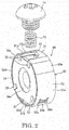
FIG. 2 is an exploded perspective view of a bearing unit, a spring and a bolt, -
FIG. 3 is an exploded perspective view of the bearing unit, -
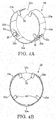
FIG. 4A is a perspective view of a support member, -
FIG. 4B is a plan view of the support member, -
FIG. 5A is a perspective view of a support member in a power steering device according to a second embodiment of the present invention, -
FIG. 5B is a plan view of the support member in the power steering device according to the second embodiment of the present invention, and -
FIG. 6 is a perspective view of a holder main body in the power steering device according to the second embodiment of the present invention. - Embodiments of the present invention are described with reference to the drawings.
- A
power steering device 100 according to an embodiment of the present invention is described with reference toFIGS. 1 to 4 . - The
power steering device 100 is a device mounted in a vehicle and configured to assist a steering force applied to a steering wheel by a driver. - As shown in
FIG. 1 , thepower steering device 100 includes aworm shaft 2 coupled to an output shaft of anelectric motor 7 and configured to rotate as theelectric motor 7 is driven and a worm wheel 1 meshed with theworm shaft 2 and configured to transmit a rotational force of theelectric motor 7 to a rack shaft configured to turn wheels. As theelectric motor 7 is driven, theworm shaft 2 rotates and the rotation of theworm shaft 2 is decelerated and transmitted to the worm wheel 1. A worm speed reducer is configured by the worm wheel 1 and theworm shaft 2. - A steering shaft includes an input shaft linked to the steering wheel, an output shaft linked to the rack shaft and a torsion bar coupling the input shaft and the output shaft. The worm wheel 1 is provided on the output shaft.
- The
electric motor 7 outputs a torque corresponding to a steering torque calculated on the basis of a twisted amount of the torsion bar twisted by relative rotation of the input shaft and the output shaft. The torque output from theelectric motor 7 is transmitted from theworm shaft 2 to the worm wheel 1 and applied as an assist torque to the output shaft of the steering shaft. - The
worm shaft 2 is housed in agear case 3 made of metal and theelectric motor 7 is mounted on thegear case 3. Thegear case 3 includes aperipheral wall 3b surrounding theworm shaft 2 and abottom wall 3c facing the tip of theworm shaft 2. Theperipheral wall 3b and thebottom wall 3c are integrally formed. As just described, thegear case 3 is excellent in waterproof property since having a bag-like structure instead of being configured to seal an opening on a bottom part by a lid. -
Tooth parts 2a meshed with those of the worm wheel 1 are formed on a part of theworm shaft 2. Theperipheral wall 3b of thegear case 3 is formed with an opening at a position corresponding to thetooth parts 2a and thetooth parts 2a of theworm shaft 2 and those of the worm wheel 1 are meshed through that opening. - A base end side of the
worm shaft 2 on the side of theelectric motor 7 is rotatably supported by a first bearing 4. In the first bearing 4, a ball is interposed between annular inner and outer rings. The outer ring of the first bearing 4 is sandwiched between astep part 3a formed in thegear case 3 and a lock nut 5 fastened in thegear case 3. The inner ring of the first bearing 4 is sandwiched between astep part 2b of theworm shaft 2 and a joint 9 press-fitted to an end part of theworm shaft 2. In this way, movements of theworm shaft 2 in an axial direction are regulated. - A tip side of the
worm shaft 2 is rotatably supported by a second bearing 11. In the second bearing 11, a ball is interposed between annular inner and outer rings. The second bearing 11 is housed in aholder 30. Theholder 30 is arranged in aholder housing hole 3d formed on a bottom side of thegear case 3 and having a circular inner peripheral surface. - A
flange part 17 having aflat end surface 17a is formed to project on the outer peripheral surface of the tip side of thegear case 3. Theflange part 17 is formed with athrough hole 13. The throughhole 13 is open on the inner peripheral surface of theholder housing hole 3d of thegear case 3. Acoil spring 12 as a biasing member is housed in the throughhole 13. An opening of the throughhole 13 open on theend surface 17a of theflange part 17 is sealed by abolt 14. - The
coil spring 12 is compressed between the tip surface of thebolt 14 and the outer peripheral surface of the second bearing 11 and biases the second bearing 11 in a direction to reduce a clearance between thetooth parts 2a of theworm shaft 2 and those of the worm wheel 1. That is, thecoil spring 12 is for biasing theworm shaft 2 toward the worm wheel 1 via the second bearing 11. - Next, the
holder 30 for housing the second bearing 11 is described mainly with reference toFIGS. 2 to 4 . - The
holder 30 includes a holdermain body 31 having a bearinghousing hole 32 for housing thesecond bearing 11, asupport member 33 to be mounted on the outer peripheral surface of the holdermain body 31 and acover plate 34 for covering thesecond bearing 11 housed in the holdermain body 31. - As shown in
FIGS. 2 and3 , the holdermain body 31 is a bottomed tubular member. The holdermain body 31 includes a disk-likebottom part 31a to be in contact with the bottom part of thegear case 3 and acylindrical cylinder part 31b surrounding the outer peripheral surface of thesecond bearing 11. The holdermain body 31 is formed with the bearinghousing hole 32 by thebottom part 31a and thecylinder part 31b. The holdermain body 31 is made of resin. - The bearing
housing hole 32 of the holdermain body 31 is so formed that thesecond bearing 11 is movable in a biasing direction of thecoil spring 12. Specifically, a pair ofplane parts 31c is formed on the inner peripheral surface of thecylinder part 31b. The pair ofplane parts 31c is formed to face each other and parallel to the biasing direction of thecoil spring 12. A dimension between the pair ofplane parts 31c is slightly longer than an outer diameter of thesecond bearing 11. Since the bearinghousing hole 32 is shaped to be elongate hole in this way, thesecond bearing 11 can move toward the worm wheel 1 in the bearinghousing hole 32 by the biasing force of thecoil spring 12. - The
cylinder part 31b of the holdermain body 31 is formed with acut 31d through which thecoil spring 12 is inserted. Further, the outer peripheral surface of thecylinder part 31b is formed withgroove parts 31e into whichprojections 33b of thesupport member 33 are to be fitted. Theprojections 33b will be described later. 7 - As shown in
FIG. 1 , a throughhole 31f through which the tip part of theworm shaft 2 is to be inserted is formed in an axial center of thebottom part 31a of the holdermain body 31. Further, the back surface of thebottom part 31a is formed with aprojection 31g to be fitted into ahole part 3e formed on the bottom part of thegear case 3 at a position deviated from the axial center. By fitting theprojection 31g of the holdermain body 31 into thehole part 3e of thegear case 3, theholder 30 is circumferentially positioned in theholder housing hole 3d of thegear case 3 by having the rotation thereof regulated. - As shown in
FIGS. 4A and 4B , thesupport member 33 is a C-shaped member formed by arcuately bending a long and narrow metal plate. Thesupport member 33 includes anopen part 33a between opposite end parts. Thesupport member 33 has an inner diameter smaller than an outer diameter of the holdermain body 31 in a state not mounted on the outer peripheral surface of the holdermain body 31. Thus, thesupport member 33 is mounted on the outer peripheral surface of the holdermain body 31 by canceling a diameter-enlarged state after the holdermain body 31 is inserted into thesupport member 33 with thesupport member 33 enlarged in diameter in an elastic region. In this way, thesupport member 33 is fitted in close contact with the outer peripheral surface of the holdermain body 31. - The
support member 33 is formed with two inwardly facingprojections 33b. Theprojection 33b is formed by inwardly bending a part between a pair of long andnarrow openings 33c formed in parallel on thesupport member 33. By fitting theprojections 33b into thegroove parts 31e formed on the outer peripheral surface of the holdermain body 31, thesupport member 33 is circumferentially positioned with respect to the holdermain body 31. In this positioned state, as shown inFIG. 2 , the circumferential position of theopen part 33a of thesupport member 33 and that of thecut 31d of the holdermain body 31 are aligned to expose the outer peripheral surface of thesecond bearing 11. Thecoil spring 12 is inserted through theopen part 33a and thecut 31d to come into contact with the exposed outer peripheral surface of thesecond bearing 11. - As shown in
FIG. 4B , thesupport member 33 includes arcuate close-contact parts 33d to be in close contact with the outer peripheral surface of thecylinder part 31b of the holdermain body 31 and arcuate bulgingparts 33e formed to bulge radially outwardly without being in close contact with the outer peripheral surface of thecylinder part 31 b. - Three bulging
parts 33e are formed at positions across theopen part 33a and at a position facing theopen part 33a. The bulgingparts 33e are formed substantially at an interval of 120°. The bulgingparts 33e are formed as arcs having a larger curvature than the close-contact parts 33d. Two close-contact parts 33d are formed between the bulgingparts 33e. Theprojections 33b for circumferentially positioning thesupport member 33 with respect to the holdermain body 31 are formed on the close-contact parts 33d. It should be noted that dashed-dotted lines shown inFIG. 4B are virtual line indicating extensions of the close-contact parts 33d. - In a state where the
holder 30 is housed in theholder housing hole 3d of thegear case 3, the three bulgingparts 33e are in contact with the inner peripheral surface of theholder housing hole 3d, whereas the two close-contact parts 33d face the inner peripheral surface of theholder housing hole 3d with small clearances defined therebetween. As just described, an outer diameter of the close-contact parts 33d of thesupport member 33 is slightly smaller than an inner diameter of theholder housing hole 3d with thesupport member 33 mounted on the outer peripheral surface of the holdermain body 31. - The three bulging
parts 33e of thesupport member 33 are slightly compressed and deformed by being in contact with the inner peripheral surface of theholder housing hole 3d in a state where theholder 30 is housed in theholder housing hole 3d of thegear case 3. Since theholder 30 is housed while being press-fitted into theholder housing hole 3d at three points, i.e. at the bulgingparts 33e formed at an interval of 120° as just described, theholder 30 is radially positioned in theholder housing hole 3d by the bulgingparts 33e and backlash in a radial direction is prevented. Since theholder 30 is so housed that the outer peripheral surface is partially press-fitted without the entire peripheral surface being pressed fitted into theholder housing hole 3d, high machining accuracy is not required in machining the inner peripheral surface of theholder housing hole 3d. Particularly, since thegear case 3 is formed into the bag-like structure in consideration of the waterproof property in the present embodiment, theholder housing hole 3d on the bottom part of thegear case 3 needs to be machined by inserting a tool into thegear case 3 through an opening of thegear case 3 on the side of theelectric motor 7 and required machining accuracy is difficult to achieve. Also considering such a situation, the present embodiment in which the outer peripheral surface of theholder 30 is partially press-fitted into theholder housing hole 3d is effective. - The bulging
parts 33e need not be arcs having a larger curvature than the close-contact parts 33d as long as they are formed to bulge radially outwardly without being in close contact with the outer peripheral surface of thecylinder part 31b. For example, the bulgingparts 33e may be arcs having a smaller curvature than the close-contact parts 33d or arcs having the same curvature as the close-contact parts 33d. - The
support member 33 includes a plurality ofclaw pieces 35 for preventing thesecond bearing 11 from coming out of the bearinghousing hole 32 of the holdermain body 31. Theclaw pieces 35 are formed to project inwardly from the peripheral edge of thesupport member 33. - If the
claw pieces 35 directly come into contact with thesecond bearing 11, they may obstruct the rotation of thesecond bearing 11 or damage thesecond bearing 11. Thus, as shown inFIG. 2 , thecover plate 34 is arranged in contact between an end surface of thecylinder part 31b of the holdermain body 31 and theclaw pieces 35 of thesupport member 33. Since thecover plate 34 is arranged to cover an end surface of thesecond bearing 11 exposed from the holdermain body 31, theclaw pieces 35 of thesupport member 33 come into contact with not thesecond bearing 11, but thecover plate 34. Thus, theclaw pieces 35 are prevented from obstructing the rotation of thesecond bearing 11 and damaging thesecond bearing 11. Thecover plate 34 is formed with a throughhole 34a through which the tip part of theworm shaft 2 is to be inserted. - The
second bearing 11 and thecover plate 34 are held by theclaw pieces 35 of thesupport member 33 mounted on the outer peripheral surface of the holdermain body 31. As just described, thesecond bearing 11, the holdermain body 31, thesupport member 33 and thecover plate 34 are unitized into a bearingunit 40 as shown inFIG. 2 . Thus, in mounting thesecond bearing 11 and theholder 30 into theholder housing hole 3d of thegear case 3, each component needs not be individually mounted and only the bearingunit 40 has to be mounted. Therefore, a mounting operation is very easy. - Next, functions and effects of the
holder 30 are described. - The
holder 30 supporting thesecond bearing 11 is fixed in thegear case 3 in a state where the three bulgingparts 33e are in contact with the inner peripheral surface of theholder housing hole 3d and slightly compressed and deformed. In this way, theholder 30 is housed while being partially press-fitted at the three bulgingparts 33e without the entire outer peripheral surface of the holdermain body 31 being press-fitted into theholder housing hole 3d. If the entire outer peripheral surface of theholder 30 is pressed-fitted into theholder housing hole 3d, parts of the outer peripheral surface of theholder 30 unevenly come into contact with the inner peripheral surface of theholder housing hole 3d and theholder 30 may loosely move in theholder housing hole 3d if the machining accuracy of the inner peripheral surface of theholder housing hole 3d is poor. In such a case, a collision sound of theholder 30 and theholder housing hole 3d is generated. However, in the present embodiment, theholder 30 is housed into theholder housing hole 3d with the outer peripheral surface partially press-fitted. Thus, even if the machining accuracy of the inner peripheral surface of theholder housing hole 3d is poor, theholder 30 is radially positioned in theholder housing hole 3d via the three bulgingparts 33e. Therefore, radial movements in theholder housing hole 3d are prevented. As a result, the generation of the collision sound of theholder 30 and theholder housing hole 3d is prevented. - Further, the
second bearing 11 is normally biased in the direction to reduce the clearance between thetooth parts 2a of theworm shaft 2 and those of the worm wheel 1 by the biasing force of thecoil spring 12. However, if a load exceeding the biasing force of thecoil spring 12 is input from a wheel side through the worm wheel 1 and theworm shaft 2, thesecond bearing 11 moves in the bearinghousing hole 32 of the holdermain body 31 against the biasing force of thecoil spring 12 and, associated with this, theholder 30 also radially moves in theholder housing hole 3d. Even in such a case, the generation of the collision sound of theholder 30 and theholder housing hole 3d is prevented since the two bulgingparts 33e formed at the positions across theopen part 33a of thesupport member 33 function as cushioning members. - Further, since the holder
main body 31 is made of resin, an amount of thermal expansion is larger as compared to thegear case 3 made of metal. Thus, if the entire outer peripheral surface of the holdermain body 31 is press-fitted into theholder housing hole 3d, the holdermain body 31 may be fractured when the holdermain body 31 thermally expands. However, since the holdermain body 31 is partially press-fitted into theholder housing hole 3d via the bulgingparts 33e of thesupport member 33 made of metal and mounted on the outer periphery, the thermal expansion of the holdermain body 31 can be accommodated by the bulgingparts 33e. Thus, the fracture of the holdermain body 31 due to thermal expansion is prevented. - According to the above embodiment, the following effects are exhibited.
- Since the
holder 30 is fixed in theholder housing hole 3d of thegear case 3 via the bulgingpart 33e, radial movements of theholder 30 in theholder housing hole 3d are prevented. Thus, the generation of the collision sound of theholder 30 and thegear case 3 can be prevented. - Further, since the
holder 30 is radially positioned in theholder housing hole 3d via the three bulgingparts 33e, it is not necessary to provide a member such as an O-ring between the outer peripheral surface of theholder 30 and the inner peripheral surface of theholder housing hole 3d. Thus, the number of components can be reduced. - Further, since the
holder 30 is housed with the outer peripheral surface partially press-fitted without the entire outer peripheral surface being press-fitted into theholder housing hole 3d, high machining accuracy is not required in machining the inner peripheral surface of theholder housing hole 3d. Thus, the bag-like structure for which it is difficult to achieve required machining accuracy, but which is excellent in waterproof property can be adopted as the structure of thegear case 3. - Next, a second embodiment of the present invention is described with reference to
FIGS. 5 and6 . The following description is centered on points of difference from the above first embodiment and the same components as in the first embodiment are denoted by the same reference signs inFIGS. 5 and6 and not described. - A
support member 33 includes a pair ofleaf spring parts 36 respectively formed at a pair of close-contact portions 33d. A holdermain body 31 includes a pair of throughholes 37 facing each other at positions displaced 90° from acut 31d through which acoil spring 12 is to be inserted. - The pair of
leaf spring parts 36 bias asecond bearing 11 from positions symmetrical with respect to a biasing direction of thecoil spring 12. Specifically, theleaf spring parts 36 are formed to face each other so as to sandwich and bias thesecond bearing 11 in directions perpendicular to the biasing direction of thecoil spring 12. Only oneend parts 36a of the pair ofleaf spring parts 36 are coupled to thesupport member 33 and the other end sides formed as free ends apply biasing forces to the outer peripheral surface of thesecond bearing 11 through the pair of throughholes 37 of the holdermain body 31. - Since the pair of
leaf spring parts 36 sandwich and bias thesecond bearing 11 in the directions perpendicular to the biasing direction of thecoil spring 12, they act to constantly hold thesecond bearing 11 in center in a bearinghousing hole 32 of the holdermain body 31. Thus, the biasing force of thecoil spring 12 stably acts on thesecond bearing 11, wherefore the backlash ofteeth parts 2a of aworm shaft 2 and those of a worm wheel 1 is stably reduced. - The configuration of the pair of
leaf spring parts 36 is not limited to the configuration for sandwiching and biasing thesecond bearing 11 in the directions perpendicular to the biasing direction of thecoil spring 12, and the pair ofleaf spring parts 36 have only to be configured to bias thesecond bearing 11 such that components of force are generated in the directions perpendicular to the biasing direction of thecoil spring 12. That is, the pair ofleaf spring parts 36 have only to be configured to bias thesecond bearing 11 from the positions symmetrical with respect to the biasing direction of thecoil spring 12. - Further, the
coil spring 12 may be omitted and the pair ofleaf spring parts 36 may also have a function of thecoil spring 12. That is, the pair ofleaf spring parts 36 may exhibit both the function of reducing the backlash of thetooth parts 2a of theworm shaft 2 and those of the worm wheel 1 and the function of constantly holding thesecond bearing 11 in center in the bearinghousing hole 32 of the holdermain body 31. In this case, the pair ofleaf spring parts 36 need to be formed to generate a component of force in the biasing direction of thecoil spring 12 and components of force in the directions perpendicular to the biasing direction of thecoil spring 12 as biasing forces applied to thesecond bearing 11 by the pair ofleaf spring parts 36. The component of force in the biasing direction of thecoil spring 12 acts to reduce the backlash of thetooth parts 2a of theworm shaft 2 and those of the worm wheel 1 and the components of force in the directions perpendicular to the biasing direction of thecoil spring 12 act to constantly hold thesecond bearing 11 in center in the bearinghousing hole 32 of the holdermain body 31. - Modifications of the above embodiments are described below.
- The above embodiments are configured such that the
support member 33 is mounted on the outer peripheral surface of the holdermain body 31. Instead of this configuration, thesupport member 33 may be omitted and the bulgingparts 33e may be directly formed on the outer peripheral surface of the holdermain body 31. - Further, in the above embodiments, the three bulging
parts 33e of thesupport member 33 are formed at the positions across theopen part 33a and the position facing theopen part 33a. The bulging part(s) 33e may be formed at position(s) other than these three positions. - Further, in the above embodiments, the worm wheel 1 is provided on the output shaft of the steering shaft. Instead of this configuration, the worm wheel 1 may be provided on a pinion shaft provided separately from the steering shaft and meshed with the rack shaft.
- Embodiments of this invention were described above, but the above embodiments are merely examples of applications of this invention, and the technical scope of this invention is not limited to the specific constitutions of the above embodiments.
- This application claims priority based on Japanese Patent Application No.
2013-267495
Claims (6)
- A power steering device, comprising:a worm shaft configured to rotate as an electric motor is driven;a worm wheel meshed with the worm shaft, the worm wheel being configured to transmit a rotational force of the electric motor to a rack shaft configured to turn wheels;a bearing that rotatably supports a tip side of the worm shaft;a gear case that houses the worm shaft;a biasing member configured to bias the worm shaft toward the worm wheel via the bearing; anda holder including a housing hole configured to house the bearing movably in a biasing direction of the biasing member, wherein
the holder includes a plurality of bulging parts formed to bulge radially outwardly, the bulging parts being configured to come into contact with an inner peripheral surface of the gear case. - The power steering device according to claim 1, wherein:the holder includes:a holder main body formed with the housing hole, anda support member to be mounted on an outer peripheral surface of the holder main body; andthe support member includes:a close-contact portion to be held in close contact with the outer peripheral surface of the holder main body, andthe bulging parts formed to bulge radially outwardly.
- The power steering device according to claim 2, wherein:the support member has a C shape with an open part; andthe bulging parts are formed at positions across the open part and at a position facing the open part.
- The power steering device according to claim 2, wherein:the support member includes a pair of leaf spring parts configured to bias the bearing from positions symmetrical with respect to the biasing direction of the biasing member by being inserted through a pair of through holes formed on the holder main body.
- The power steering device according to claim 2, wherein:the support member includes a projection on the close-contact portion, the projection being fitted into a groove part formed on the outer peripheral surface of the holder main body.
- The power steering device according to claim 2, wherein:the support member includes a claw piece configured to prevent the bearing from coming out of the housing hole of the holder main body.
Applications Claiming Priority (2)
| Application Number | Priority Date | Filing Date | Title |
|---|---|---|---|
| JP2013267495A JP6313969B2 (en) | 2013-12-25 | 2013-12-25 | Power steering device |
| PCT/JP2014/082856 WO2015098548A1 (en) | 2013-12-25 | 2014-12-11 | Power steering device |
Publications (2)
| Publication Number | Publication Date |
|---|---|
| EP3095672A1 true EP3095672A1 (en) | 2016-11-23 |
| EP3095672A4 EP3095672A4 (en) | 2017-10-11 |
Family
ID=53478412
Family Applications (1)
| Application Number | Title | Priority Date | Filing Date |
|---|---|---|---|
| EP14873868.5A Withdrawn EP3095672A4 (en) | 2013-12-25 | 2014-12-11 | Power steering device |
Country Status (5)
| Country | Link |
|---|---|
| US (1) | US10077067B2 (en) |
| EP (1) | EP3095672A4 (en) |
| JP (1) | JP6313969B2 (en) |
| CN (1) | CN105848988B (en) |
| WO (1) | WO2015098548A1 (en) |
Cited By (3)
| Publication number | Priority date | Publication date | Assignee | Title |
|---|---|---|---|---|
| WO2018220317A1 (en) * | 2017-05-31 | 2018-12-06 | Jtekt Europe | Sealing plug for a reducer casing, bearing a meshing play-compensating carriage |
| DE102017129429A1 (en) * | 2017-12-11 | 2019-06-13 | Schaeffler Technologies AG & Co. KG | worm gear |
| EP3549844A4 (en) * | 2016-12-29 | 2020-08-05 | erae AMS Co., Ltd. | ELECTRIC POWER STEERING SYSTEM |
Families Citing this family (18)
| Publication number | Priority date | Publication date | Assignee | Title |
|---|---|---|---|---|
| US10100873B2 (en) * | 2014-12-09 | 2018-10-16 | Ford Global Technologies, Llc | Radially deflectable bushing and steering gear assembly using the same |
| KR102187588B1 (en) * | 2015-06-29 | 2020-12-07 | 현대자동차주식회사 | Clearance compensation device of motor driven power steering apparatus |
| KR102300787B1 (en) * | 2015-09-18 | 2021-09-10 | 현대모비스 주식회사 | Elecric power steering apparatus |
| KR102101664B1 (en) * | 2015-12-31 | 2020-04-27 | 남양넥스모 주식회사 | Structure of bearing holder for electric power steering system |
| JP6167198B1 (en) * | 2016-03-25 | 2017-07-19 | Kyb株式会社 | Electric power steering device and method of manufacturing electric power steering device |
| JP6811083B2 (en) * | 2016-12-12 | 2021-01-13 | 株式会社小糸製作所 | Cleaners and vehicles with cleaners |
| JP6784587B2 (en) * | 2016-12-20 | 2020-11-11 | Kyb株式会社 | Power steering device |
| CN106741140B (en) * | 2016-12-20 | 2022-12-16 | 博世华域转向系统有限公司 | Vibration/noise reduction structure of electric power-assisted driving unit |
| KR102635273B1 (en) * | 2017-02-01 | 2024-02-13 | 에이치엘만도 주식회사 | Reducer of Electric Power Steering Apparatus |
| JP2018155301A (en) * | 2017-03-16 | 2018-10-04 | 株式会社ジェイテクト | Method for manufacturing worm reducer, worm reducer, and electric power steering device |
| JP6875963B2 (en) * | 2017-08-31 | 2021-05-26 | Kyb株式会社 | Power steering device |
| JP6875962B2 (en) * | 2017-08-31 | 2021-05-26 | Kyb株式会社 | Power steering device |
| KR101993295B1 (en) * | 2017-12-19 | 2019-06-26 | 주식회사 만도 | Reducer of Electric Power Steering Apparatus |
| JP6994405B2 (en) * | 2018-02-23 | 2022-01-14 | 日立Astemo株式会社 | Steering device |
| JP7133993B2 (en) * | 2018-06-07 | 2022-09-09 | 株式会社ユーシン | electric actuator |
| JP7310551B2 (en) | 2019-11-01 | 2023-07-19 | 株式会社ジェイテクト | Worm reducer and method for manufacturing worm reducer |
| KR102765344B1 (en) * | 2020-01-16 | 2025-02-13 | 생-고뱅 퍼포먼스 플라스틱스 렌콜 리미티드 | Bearing for steering assembly |
| JP7634418B2 (en) * | 2021-04-28 | 2025-02-21 | ナブテスコ株式会社 | Power transmission device and gear mechanism meshing adjustment device |
Family Cites Families (12)
| Publication number | Priority date | Publication date | Assignee | Title |
|---|---|---|---|---|
| JPH01102515U (en) * | 1987-12-28 | 1989-07-11 | ||
| JP3646205B2 (en) | 2000-09-04 | 2005-05-11 | 光洋精工株式会社 | Electric power steering device |
| JP4356485B2 (en) * | 2004-03-09 | 2009-11-04 | 株式会社ジェイテクト | Electric power steering device |
| US7052183B2 (en) * | 2004-06-15 | 2006-05-30 | Honeywell International Inc. | Composite resilient mount |
| FR2911171B1 (en) | 2007-01-10 | 2009-08-28 | Jtekt Europ Soc Par Actions Si | MECHANICAL SPEED REDUCER OF THE SCREW TYPE WITHOUT END AND TANGENT WHEEL |
| DE102008042477A1 (en) * | 2008-09-30 | 2010-04-01 | Zf Lenksysteme Gmbh | Floating bearing for worm in steering gear of servo-assisted steering mechanism, has bearing bush with bearing ring provided with flexible elements in sections, where flexible elements are attached at outer or inner wall of bearing ring |
| JP5285029B2 (en) * | 2010-06-10 | 2013-09-11 | 日立オートモティブシステムズ株式会社 | Electric power steering device |
| JP5551642B2 (en) * | 2011-03-22 | 2014-07-16 | カヤバ工業株式会社 | Power steering device |
| JP2013071679A (en) * | 2011-09-28 | 2013-04-22 | Showa Corp | Electric power steering device |
| JP5999423B2 (en) * | 2011-11-25 | 2016-09-28 | 株式会社ジェイテクト | Electric power steering device |
| JP2013184502A (en) * | 2012-03-06 | 2013-09-19 | Jtekt Corp | Electric power steering apparatus |
| JP5878064B2 (en) * | 2012-03-30 | 2016-03-08 | 株式会社ショーワ | Electric power steering device |
-
2013
- 2013-12-25 JP JP2013267495A patent/JP6313969B2/en not_active Expired - Fee Related
-
2014
- 2014-12-11 CN CN201480070558.5A patent/CN105848988B/en not_active Expired - Fee Related
- 2014-12-11 EP EP14873868.5A patent/EP3095672A4/en not_active Withdrawn
- 2014-12-11 US US15/107,923 patent/US10077067B2/en not_active Expired - Fee Related
- 2014-12-11 WO PCT/JP2014/082856 patent/WO2015098548A1/en not_active Ceased
Cited By (5)
| Publication number | Priority date | Publication date | Assignee | Title |
|---|---|---|---|---|
| EP3549844A4 (en) * | 2016-12-29 | 2020-08-05 | erae AMS Co., Ltd. | ELECTRIC POWER STEERING SYSTEM |
| WO2018220317A1 (en) * | 2017-05-31 | 2018-12-06 | Jtekt Europe | Sealing plug for a reducer casing, bearing a meshing play-compensating carriage |
| FR3067084A1 (en) * | 2017-05-31 | 2018-12-07 | Jtekt Europe | SEAL PLUG FOR REDUCER HOUSING CARRYING A GEAR SET COMPENSATION TROLLEY |
| US11635135B2 (en) | 2017-05-31 | 2023-04-25 | Jtekt Europe | Sealing plug for a reducer casing, bearing a meshing play-compensating carriage |
| DE102017129429A1 (en) * | 2017-12-11 | 2019-06-13 | Schaeffler Technologies AG & Co. KG | worm gear |
Also Published As
| Publication number | Publication date |
|---|---|
| CN105848988B (en) | 2018-07-06 |
| CN105848988A (en) | 2016-08-10 |
| WO2015098548A1 (en) | 2015-07-02 |
| US10077067B2 (en) | 2018-09-18 |
| US20160318545A1 (en) | 2016-11-03 |
| JP2015123769A (en) | 2015-07-06 |
| JP6313969B2 (en) | 2018-04-18 |
| EP3095672A4 (en) | 2017-10-11 |
Similar Documents
| Publication | Publication Date | Title |
|---|---|---|
| US10077067B2 (en) | Power steering device | |
| US10183693B2 (en) | Electric power steering device | |
| KR101718683B1 (en) | Rotary actuator and strain wave gearing reduction drive unit | |
| US10059366B2 (en) | Electrically driven power steering device | |
| US10106132B2 (en) | Electric parking brake driving device and electric parking brake device | |
| EP2562438B1 (en) | Shaft coupling structure and steering system | |
| WO2015115324A1 (en) | Reduction gear with brake | |
| JP5327724B2 (en) | Rotating electric machine, robot, manufacturing method of rotating electric machine, hollow shaft | |
| EP2367270A2 (en) | Electric rotary actuator | |
| JP5336823B2 (en) | Worm reducer and electric power steering device | |
| US20170363176A1 (en) | Speed reducer | |
| WO2019198525A1 (en) | Articulation unit, robot arm, and robot | |
| CN103711842A (en) | Wave gear unit with input bearings | |
| EP3549844A1 (en) | Electric power steering system | |
| JP6052988B2 (en) | Power steering device | |
| JPWO2015037087A1 (en) | Wave generator and wave gear device | |
| EP2963782B1 (en) | Motor device | |
| JP2011179658A (en) | Vehicular electric brake device | |
| JP6784587B2 (en) | Power steering device | |
| JP5336822B2 (en) | Gear device and electric power steering device | |
| JP2011179656A (en) | Electric brake device for vehicle | |
| JP2020197252A (en) | Rotation transmission mechanism and motor device | |
| JP2005151646A (en) | Motor support structure and electric actuator | |
| JP2015075200A (en) | Linear actuator | |
| JP2017009036A (en) | Reduction gear |
Legal Events
| Date | Code | Title | Description |
|---|---|---|---|
| PUAI | Public reference made under article 153(3) epc to a published international application that has entered the european phase |
Free format text: ORIGINAL CODE: 0009012 |
|
| 17P | Request for examination filed |
Effective date: 20160630 |
|
| AK | Designated contracting states |
Kind code of ref document: A1 Designated state(s): AL AT BE BG CH CY CZ DE DK EE ES FI FR GB GR HR HU IE IS IT LI LT LU LV MC MK MT NL NO PL PT RO RS SE SI SK SM TR |
|
| AX | Request for extension of the european patent |
Extension state: BA ME |
|
| DAX | Request for extension of the european patent (deleted) | ||
| A4 | Supplementary search report drawn up and despatched |
Effective date: 20170911 |
|
| RIC1 | Information provided on ipc code assigned before grant |
Ipc: F16H 1/16 20060101ALI20170905BHEP Ipc: B62D 5/04 20060101AFI20170905BHEP |
|
| STAA | Information on the status of an ep patent application or granted ep patent |
Free format text: STATUS: THE APPLICATION HAS BEEN WITHDRAWN |
|
| 18W | Application withdrawn |
Effective date: 20181219 |