EP3095656B1 - Procede de selection d'un mode de fonctionnement d'un vehicule automobile hybride - Google Patents
Procede de selection d'un mode de fonctionnement d'un vehicule automobile hybride Download PDFInfo
- Publication number
- EP3095656B1 EP3095656B1 EP16000919.7A EP16000919A EP3095656B1 EP 3095656 B1 EP3095656 B1 EP 3095656B1 EP 16000919 A EP16000919 A EP 16000919A EP 3095656 B1 EP3095656 B1 EP 3095656B1
- Authority
- EP
- European Patent Office
- Prior art keywords
- mode
- evaluation
- modes
- ideal
- determined
- Prior art date
- Legal status (The legal status is an assumption and is not a legal conclusion. Google has not performed a legal analysis and makes no representation as to the accuracy of the status listed.)
- Active
Links
Images


Classifications
-
- B—PERFORMING OPERATIONS; TRANSPORTING
- B60—VEHICLES IN GENERAL
- B60W—CONJOINT CONTROL OF VEHICLE SUB-UNITS OF DIFFERENT TYPE OR DIFFERENT FUNCTION; CONTROL SYSTEMS SPECIALLY ADAPTED FOR HYBRID VEHICLES; ROAD VEHICLE DRIVE CONTROL SYSTEMS FOR PURPOSES NOT RELATED TO THE CONTROL OF A PARTICULAR SUB-UNIT
- B60W10/00—Conjoint control of vehicle sub-units of different type or different function
- B60W10/04—Conjoint control of vehicle sub-units of different type or different function including control of propulsion units
- B60W10/06—Conjoint control of vehicle sub-units of different type or different function including control of propulsion units including control of combustion engines
-
- B—PERFORMING OPERATIONS; TRANSPORTING
- B60—VEHICLES IN GENERAL
- B60W—CONJOINT CONTROL OF VEHICLE SUB-UNITS OF DIFFERENT TYPE OR DIFFERENT FUNCTION; CONTROL SYSTEMS SPECIALLY ADAPTED FOR HYBRID VEHICLES; ROAD VEHICLE DRIVE CONTROL SYSTEMS FOR PURPOSES NOT RELATED TO THE CONTROL OF A PARTICULAR SUB-UNIT
- B60W10/00—Conjoint control of vehicle sub-units of different type or different function
- B60W10/04—Conjoint control of vehicle sub-units of different type or different function including control of propulsion units
- B60W10/08—Conjoint control of vehicle sub-units of different type or different function including control of propulsion units including control of electric propulsion units, e.g. motors or generators
-
- B—PERFORMING OPERATIONS; TRANSPORTING
- B60—VEHICLES IN GENERAL
- B60W—CONJOINT CONTROL OF VEHICLE SUB-UNITS OF DIFFERENT TYPE OR DIFFERENT FUNCTION; CONTROL SYSTEMS SPECIALLY ADAPTED FOR HYBRID VEHICLES; ROAD VEHICLE DRIVE CONTROL SYSTEMS FOR PURPOSES NOT RELATED TO THE CONTROL OF A PARTICULAR SUB-UNIT
- B60W20/00—Control systems specially adapted for hybrid vehicles
- B60W20/10—Controlling the power contribution of each of the prime movers to meet required power demand
- B60W20/11—Controlling the power contribution of each of the prime movers to meet required power demand using model predictive control [MPC] strategies, i.e. control methods based on models predicting performance
-
- B—PERFORMING OPERATIONS; TRANSPORTING
- B60—VEHICLES IN GENERAL
- B60W—CONJOINT CONTROL OF VEHICLE SUB-UNITS OF DIFFERENT TYPE OR DIFFERENT FUNCTION; CONTROL SYSTEMS SPECIALLY ADAPTED FOR HYBRID VEHICLES; ROAD VEHICLE DRIVE CONTROL SYSTEMS FOR PURPOSES NOT RELATED TO THE CONTROL OF A PARTICULAR SUB-UNIT
- B60W30/00—Purposes of road vehicle drive control systems not related to the control of a particular sub-unit, e.g. of systems using conjoint control of vehicle sub-units
- B60W30/18—Propelling the vehicle
- B60W30/182—Selecting between different operative modes, e.g. comfort and performance modes
-
- B—PERFORMING OPERATIONS; TRANSPORTING
- B60—VEHICLES IN GENERAL
- B60W—CONJOINT CONTROL OF VEHICLE SUB-UNITS OF DIFFERENT TYPE OR DIFFERENT FUNCTION; CONTROL SYSTEMS SPECIALLY ADAPTED FOR HYBRID VEHICLES; ROAD VEHICLE DRIVE CONTROL SYSTEMS FOR PURPOSES NOT RELATED TO THE CONTROL OF A PARTICULAR SUB-UNIT
- B60W2710/00—Output or target parameters relating to a particular sub-units
- B60W2710/06—Combustion engines, Gas turbines
- B60W2710/0677—Engine power
-
- B—PERFORMING OPERATIONS; TRANSPORTING
- B60—VEHICLES IN GENERAL
- B60W—CONJOINT CONTROL OF VEHICLE SUB-UNITS OF DIFFERENT TYPE OR DIFFERENT FUNCTION; CONTROL SYSTEMS SPECIALLY ADAPTED FOR HYBRID VEHICLES; ROAD VEHICLE DRIVE CONTROL SYSTEMS FOR PURPOSES NOT RELATED TO THE CONTROL OF A PARTICULAR SUB-UNIT
- B60W2710/00—Output or target parameters relating to a particular sub-units
- B60W2710/08—Electric propulsion units
- B60W2710/083—Torque
-
- B—PERFORMING OPERATIONS; TRANSPORTING
- B60—VEHICLES IN GENERAL
- B60W—CONJOINT CONTROL OF VEHICLE SUB-UNITS OF DIFFERENT TYPE OR DIFFERENT FUNCTION; CONTROL SYSTEMS SPECIALLY ADAPTED FOR HYBRID VEHICLES; ROAD VEHICLE DRIVE CONTROL SYSTEMS FOR PURPOSES NOT RELATED TO THE CONTROL OF A PARTICULAR SUB-UNIT
- B60W2710/00—Output or target parameters relating to a particular sub-units
- B60W2710/08—Electric propulsion units
- B60W2710/086—Power
-
- Y—GENERAL TAGGING OF NEW TECHNOLOGICAL DEVELOPMENTS; GENERAL TAGGING OF CROSS-SECTIONAL TECHNOLOGIES SPANNING OVER SEVERAL SECTIONS OF THE IPC; TECHNICAL SUBJECTS COVERED BY FORMER USPC CROSS-REFERENCE ART COLLECTIONS [XRACs] AND DIGESTS
- Y02—TECHNOLOGIES OR APPLICATIONS FOR MITIGATION OR ADAPTATION AGAINST CLIMATE CHANGE
- Y02T—CLIMATE CHANGE MITIGATION TECHNOLOGIES RELATED TO TRANSPORTATION
- Y02T10/00—Road transport of goods or passengers
- Y02T10/10—Internal combustion engine [ICE] based vehicles
- Y02T10/40—Engine management systems
-
- Y—GENERAL TAGGING OF NEW TECHNOLOGICAL DEVELOPMENTS; GENERAL TAGGING OF CROSS-SECTIONAL TECHNOLOGIES SPANNING OVER SEVERAL SECTIONS OF THE IPC; TECHNICAL SUBJECTS COVERED BY FORMER USPC CROSS-REFERENCE ART COLLECTIONS [XRACs] AND DIGESTS
- Y02—TECHNOLOGIES OR APPLICATIONS FOR MITIGATION OR ADAPTATION AGAINST CLIMATE CHANGE
- Y02T—CLIMATE CHANGE MITIGATION TECHNOLOGIES RELATED TO TRANSPORTATION
- Y02T10/00—Road transport of goods or passengers
- Y02T10/60—Other road transportation technologies with climate change mitigation effect
- Y02T10/62—Hybrid vehicles
-
- Y—GENERAL TAGGING OF NEW TECHNOLOGICAL DEVELOPMENTS; GENERAL TAGGING OF CROSS-SECTIONAL TECHNOLOGIES SPANNING OVER SEVERAL SECTIONS OF THE IPC; TECHNICAL SUBJECTS COVERED BY FORMER USPC CROSS-REFERENCE ART COLLECTIONS [XRACs] AND DIGESTS
- Y02—TECHNOLOGIES OR APPLICATIONS FOR MITIGATION OR ADAPTATION AGAINST CLIMATE CHANGE
- Y02T—CLIMATE CHANGE MITIGATION TECHNOLOGIES RELATED TO TRANSPORTATION
- Y02T10/00—Road transport of goods or passengers
- Y02T10/80—Technologies aiming to reduce greenhouse gasses emissions common to all road transportation technologies
- Y02T10/84—Data processing systems or methods, management, administration
-
- Y—GENERAL TAGGING OF NEW TECHNOLOGICAL DEVELOPMENTS; GENERAL TAGGING OF CROSS-SECTIONAL TECHNOLOGIES SPANNING OVER SEVERAL SECTIONS OF THE IPC; TECHNICAL SUBJECTS COVERED BY FORMER USPC CROSS-REFERENCE ART COLLECTIONS [XRACs] AND DIGESTS
- Y10—TECHNICAL SUBJECTS COVERED BY FORMER USPC
- Y10S—TECHNICAL SUBJECTS COVERED BY FORMER USPC CROSS-REFERENCE ART COLLECTIONS [XRACs] AND DIGESTS
- Y10S903/00—Hybrid electric vehicles, HEVS
- Y10S903/902—Prime movers comprising electrical and internal combustion motors
- Y10S903/903—Prime movers comprising electrical and internal combustion motors having energy storing means, e.g. battery, capacitor
- Y10S903/93—Conjoint control of different elements
Definitions
- the invention relates to a method for selecting an operating mode of a hybrid vehicle, in particular a method in which from a given set of possible operating modes of a hybrid powertrain optimal for the current operating time with respect to predetermined target criteria operating mode is selected with a corresponding optimal power distribution in the drive train.
- the drive train is extended by at least one electrical machine and an associated electrical storage system.
- various other operating modes such as electric driving, a boost operation, a brake recuperation, etc.
- the various modes of operation of a hybrid powertrain must be sensibly used in vehicle operation in order to achieve the greatest possible reduction in fuel consumption.
- other goals should also be taken into account, since the increase in fuel efficiency always takes place in the area of conflict between emission minimization, component protection and / or driving comfort.
- it is therefore necessary to select an optimum operating mode with a corresponding optimum power distribution in the drive train from a predefined set of possible operating modes of the hybridized powertrain for the current operating time with regard to the predefined target criteria.
- optimal controls which include a prediction horizon in the optimization problem (also called model-based predictive control (MPR)).
- MPR model-based predictive control
- Such approaches determine based on their input information, in a certain preview window (prediction horizon) in a given search space for the model under consideration an optimal trajectory of a state variable of the system, for example, the state of charge of the energy storage.
- AI method-based operating strategies for controlling the energy systems in the hybrid vehicle are known.
- publication [2] proposes a total cost function by means of which, in addition to the target criterion "fuel efficiency”, further target criteria such as, for example, drivability (ride comfort) are taken into account.
- target criteria such as, for example, drivability (ride comfort)
- partial cost functions correspond to the individual target criteria combined into a total cost function by means of a summation and then calculates the decision regarding the operating strategy from the total cost function.
- the US 2015/0051775 A1 and the US 2011/0130901 A1 disclose methods for selecting a mode of operation of a hybrid vehicle in which, from a given set of possible modes of operation of a hybrid powertrain, an optimum mode with a corresponding optimal power distribution in the driveline is selected for the current operating time with respect to predetermined target criteria.
- a disadvantage of the known approaches is that the optimization approaches based on such a combined total cost function require high computational effort and often are not suitable for real-time operation with regard to the limits of the computing capacity of current control devices. Furthermore, these approaches have the disadvantage that the optimization methods can not usually be adapted to further or changed target criteria with little adaptation effort, since interactions between the individual target criteria exist and adding additional sub-cost functions usually requires complex changes to the analytical formula of the total cost function ,
- the object of the invention is, in particular, to provide a method for selecting a mode of operation of a hybrid vehicle in which, from a predefined set of possible modes of operation of a hybrid powertrain, an optimum mode of operation for the current operating time with respect to predetermined target criteria can be selected and with which the risk of erroneous decisions is minimized and with the same amount of computing time can be saved. Furthermore, a method is to be provided which can be easily and intuitively extended to additional target criteria.
- a method for selecting a mode of operation of a hybrid vehicle in which, in a multi-stage process, one of the set of possible modes of operation of the vehicle or of the drive train with regard to predetermined optimization criteria, optimum operating mode is selected together with an optimal power distribution in the drive train.
- the optimization criteria are also referred to below as the target criteria.
- the decision to determine an optimal power distribution in the drive train is decoupled from the decision or selection of an optimal operating mode, ie, first the optimum power distribution is determined determined for each possible operating mode and then selected on the basis of this calculation result, the optimum operating conditions with respect to the target criteria.
- a method of selecting the mode of operation of a hybrid vehicle in which a selected optimum operating mode with a corresponding optimum power distribution in the driveline is selected from a given set of possible modes of operation of a hybrid powertrain for the current operating time with respect to predetermined target criteria.
- at least one evaluation variable is defined or determined in advance for the quantitative description of the respective target criterion.
- the term "advance” is understood to mean a determination of the evaluation variables that are "offline", ie. H. not in the driving operation of the vehicle takes place, but already before or at the programmable device of the vehicle control, which is designed to carry out the online method.
- the method further comprises the following steps: For each mode of operation of a first choice of possible modes, the possible power distributions in the powertrain and the values of the evaluation variable quantitatively describing the target criteria are determined, the values of the evaluation variables being calculated for each of the particular power distributions of the respective mode, at least if their values are dependent on the power distribution , Each operating point of a possible power distribution of an operating mode is thus assigned in each case a value of each of the evaluation variables.
- the target criterion of maximizing energy efficiency can be described quantitatively by, for example, a rating variable indicating the efficiency of the electric traction machine. The efficiency is then determined in each operating mode for each of the specific power distributions.
- an optimal power distribution in the powertrain is determined by means of the determined values of the evaluation variables.
- an optimum operating mode is selected by means of those values of the evaluation variables which they have for the operating modes of the first selection in each case at the operating point of the determined optimum power distribution.
- the corresponding predetermined optimal power distribution for that mode is set.
- each operating mode independently of the other which would be the currently optimal power distribution in the drive train.
- One advantage of this is that it avoids cross-influences from other modes in determining the optimal power distribution for a mode of operation. Only in a subsequent step, the individual operating modes are then compared with each other by means of the evaluation variables, for which purpose only those values of the valuation variables are used which have these in the operating points of the previously determined optimal power distributions.
- the term operating mode of a hybrid powertrain is understood in this document to mean a combination of a specific powertrain configuration and the form of the energy flows in the components involved.
- the possible modes of operation of the powertrain may include at least two of the following operating modes known per se: a purely internal combustion engine driving; a purely electric driving with the internal combustion engine switched off; an electric driving with internal combustion engine in the idling mode; a boost operation in which the total drive power is above the power that currently can be provided solely by the internal combustion engine, and wherein the additional power is provided by the electric traction machine powered by the electric traction energy storage; a sailing operation, d. H.
- a rolling operation in which the internal combustion engine and / or the regenerative electric machine are not dragged by the kinetic energy of the vehicle; a brake recuperation; an electric starting; a load point boost; a load point reduction; and a so-called GenSet operation, in which the output from the engine power is converted by the electric machine into electrical power to supply the ancillaries and / or to charge the electrical energy storage without a moment is put on the drive wheels.
- a power distribution indicates the distribution of the total power of the drive train to the individual components of the drive unit in the hybridized powertrain with regard to a driver's current requested performance (eg in the form of a positive or negative driver request torque).
- the hybrid vehicle is a parallel hybrid vehicle with an internal combustion engine and an electric traction engine, which are operable independently of each other, but on a common shaft so that they are always moved in the coupled case at the same speed and add their moments.
- the power distribution in the powertrain corresponds to the distribution of the driver's desired torque to the torque (torque) of the internal combustion engine and the torque (moment) of the electric machine.
- the possible power distributions in the drive train for each operating mode can thus be indicated by the torques that can be generated by the electric traction machine in this operating mode, which are limited by the performance of the electric machine.
- the optimal power distribution per mode for a parallel hybrid vehicle may be indicated by an optimal torque of the electric traction machine with respect to the predetermined target criteria. It is emphasized, however, that the method is not limited to parallel hybrid vehicles.
- the optimal selection of an operating mode is understood as the selection of that operating mode which offers the best possible compromise with regard to the several predetermined target criteria.
- target criteria can be specified, such as the conditioning of the energy storage, a fuel consumption minimization and / or the highest possible driving comfort.
- at least one evaluation variable is defined, which can quantitatively describe the respective target criterion.
- the target criterion of driving comfort can be described quantitatively, for example, with a rating variable that indicates a change in the current torque, in particular the occurrence of a torque jump. The higher the torque jumps, the lower the ride comfort for the driver.
- an evaluation variable can be used which indicates the fuel mass flow permeated in the cylinders of an internal combustion engine.
- the following steps are performed to determine the optimum power distributions, which are respectively determined for each operating mode of the first selection of possible operating modes, the steps being carried out for each operating mode of the first selection: Determining an optimum value of each evaluation variable in the respective operating mode, which is determined on the basis of the previously determined values of the respective evaluation variable in the respective operating mode.
- This optimum value is hereinafter referred to as "first optimum value” to distinguish this optimum value from a subsequent "second optimum value", which is determined in the context of the subsequent selection of the optimum mode.
- a weighted first deviation of the values of the respective rating variable from the determined first optimum value of the respective rating variable is determined.
- these weighted first deviations for the rating variables are also determined in each mode. For each operating point of a possible power distribution of an operating mode, this weighted first deviation of each of the evaluation variables is thus calculated.
- a determination of the optimal power distribution of the respective operating mode is subsequently carried out using a predetermined first decision rule which defines an optimum power distribution as a function of the determined weighted first deviations of the evaluation variables.
- the first optimal value is set as an extreme value of the determined values of the respective evaluation variable in the respective operating mode.
- the maximum value of the values of the evaluation variables that result for the possible power distributions of a mode is set as the respective first optimum value.
- An advantage of this embodiment is that the various target criteria do not have to be summed up in the form of individual partial cost functions to form a total cost function. Instead, each target criterion is first evaluated on its own and independently of the other target criteria with regard to the different operating modes and possible power distributions, and then transferred by means of the weighted deviations to a common evaluation scheme.
- This approach offers the advantage that the process can easily be extended by further desired target criteria if required. In this case, it is only necessary to define a suitable further evaluation variable for the new target criterion, which quantitatively describes the target criterion, and to carry out the aforementioned steps analogously in addition to the further evaluation variable. An adaptation of a complex mathematical formula, as would be necessary for a total cost function, is not required.
- the following steps are performed to select an optimal mode of operation from the first selection of possible modes of operation: For each valuation variable, a second optimal value of the valuation variable, which is valid for all operating modes of the first selection, is determined on the basis of its specific values. In contrast to the first optimum value, which is determined as the "local" optimum value for each evaluation variable in each operating mode, the second optimum value is determined as a "global" optimum value valid for all operating modes, so that a second optimum value is determined for each evaluation variable, independently from the operating mode.
- a weighted second deviation determined for each evaluation variable in each mode of the first selection and each having a weighted deviation of the second optimum value of the respective evaluation variable from the value of the evaluation variable at the operating point of the first variable certain optimum power distribution for the respective operating mode indicates.
- the first Selection determines a weighted difference in magnitude that indicates a deviation of the value of the evaluation variable in the optimal performance distribution from the mode-independent second optimal value of the evaluation variable.
- the selection of the optimum mode is performed using a predetermined second decision rule which evaluates the modes of the first selection as a function of the weighted second deviations of the evaluation variables and determines an optimal mode of operation.
- the second optimum value is preferably set as an extreme value of the values of the respective evaluation variable at the operating point of the previously determined optimal power distribution in all modes of the first selection.
- the second optimum value of a particular evaluation variable thus corresponds to the maximization value of the values of these evaluation variables in the different operating modes at the operating point of the optimal power distribution.
- the target criterion is a minimization target, then the minimum of these values is set as the second optimum value.
- the second optimum value is given as a set point independent of the determined values of the respective evaluation variable, which in turn can be calculated in accordance with current vehicle information.
- At least one weighting factor or weighting factor can be provided for each weighting variable which determines the absolute difference of the values of the weighting variables from the first and second optimum values of the respective Valuation variable on a dimensionless basis or common cost base for all valuation variables, d.
- assessment variables that quantitatively describe a wide variety of target criteria, such as the maximization of the energy efficiency of the electric traction engine, fuel consumption minimization, emission minimization, etc., can be transferred to a common and therefore comparable basis and evaluated at the same time.
- a rating in this sense means that a deviation of, for example, x% of a first variable that, for example, evaluates energy efficiency, from its Optimal value may be rated more critically than a 10% deviation of a second evaluation variable describing an emission target from its optimum value. This different weighting or evaluation of the evaluation variables can thus be carried out in a simple manner on the basis of the determination of the weighting factors.
- Such selection of an optimal element from a plurality of evaluation variable-valued variants using decision rules is known per se from the field of game theory or the field of multi-criteria decision problems.
- decision rules the various types of decision rules known per se in these fields can be used, such as the minimax principle or the so-called lexicographical order, etc. It should be noted that the known decision rules each have different strengths and weaknesses, so that the Using a particular decision rule always brings certain advantages and disadvantages.
- the present inventive method for selecting an optimal operating mode if the second decision rule is such that the weighted second deviations of the evaluation variables are respectively summed up for one operating mode and the operating mode is set as the optimum operating mode whose sum value of the summed second deviations is minimal.
- the operating mode is thus selected on the basis of the sum values as the optimum operating mode, which has the lowest overall damage sum in the form of the summed second deviations.
- the first decision rule which is used to evaluate the first deviations, ie the deviations from the local first optimum values
- the first decision rule is a minimax decision rule.
- the largest first deviation is determined from the values of the weighted first deviations of the evaluation variables and the operating point which is the smallest of the greatest first deviations determined in this way is defined as the operating point of the optimum power distribution.
- the "worst case" is minimized, which according to findings of the inventors in the determination of the optimal power distribution allows a better compromise of the target criteria than a simple addition.
- a further particularly advantageous embodiment of the invention provides that the first selection of the operating modes on the basis of which the aforementioned determination of the optimal power distribution per operating mode and the subsequent determination of the optimum operating mode is already possible by operating modes of the hybrid vehicle which are possible in principle Current vehicle movement state are not possible and / or are excluded due to other restriction rules, is adjusted.
- This limitation of the operating modes allows a significant reduction of the computational effort in the subsequent determination of the optimal power distribution and the optimal mode.
- the determination of the first selection of the operating modes thus comprises the following steps: specification of possible vehicle movement states of the hybrid vehicle, specification of possible operating modes of the drive train and specification of an assignment which indicates which of the possible operating modes are permissible in which vehicle movement state; Determining a current vehicle motion condition; and restricting the modes of operation of the vehicle to those associated with the determined current vehicle motion state.
- the predetermined possible vehicle movement states may include, for example, a vehicle standstill, a braking operation and a driving operation (without braking), hereinafter also referred to as "driving".
- a vehicle movement state “driving” the modes of combustion engine driving, electric driving, load point increase and load point reduction can be assigned.
- the vehicle movement condition "braking” may be assigned to the modes of conventional braking, brake regeneration and sailing.
- the vehicle movement state "standstill” may be assigned the operating modes idle and the GenSet.
- At least one restriction rule is specified, which determines depending on at least one operating parameter and preferably independent of a current torque request and the current vehicle motion state, which modes are currently available.
- a further restriction of the operating modes of the vehicle can then be made to those currently available.
- an availability of components in the drive train can be tested, in particular an electrical energy store and / or an electric traction machine.
- the restriction rule can specify that all operating modes that require the use of the electrical machine are currently not permitted if the electrical energy store exceeds predetermined temperature limits and / or is outside of predetermined charge state limits. In this way, those operating modes that are not available in the current operating state of the vehicle can thus be excluded even before the optimal power distribution for each operating mode is calculated.
- predetermined values of the power distributions of the operating modes which are to be excluded as possible operating points can be determined on the basis of predefined exclusion criteria.
- the exclusion criteria are preferably defined so that any potential distribution of benefits that is not excluded is generally an acceptable selection candidate.
- the invention further relates to a hybrid vehicle, in particular a utility vehicle, comprising a control device for selecting an operating mode of the hybrid vehicle that is configured to perform the method as disclosed herein.
- a hybrid vehicle in particular a utility vehicle
- a control device for selecting an operating mode of the hybrid vehicle that is configured to perform the method as disclosed herein.
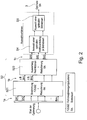
- FIG. 1 shows an exemplary flowchart for illustrating the steps of a method for selecting a mode of operation of a hybrid vehicle according to a preferred embodiment.
- the hybrid vehicle is designed as a parallel hybrid vehicle, in particular as such a commercial vehicle.
- the per se known hybrid powertrain comprises an internal combustion engine and an electric traction machine, wherein the internal combustion engine and the electric traction machine, hereinafter also referred to as electric machine or electric motor, speed-coupled via a common shaft, but are independently controllable.
- the various modes of operation should be used meaningfully in vehicle operation, in order to achieve the greatest possible reduction in fuel consumption, with other predetermined objectives to be considered, such as maximizing the energy efficiency of the electric traction engine, the emission minimization and / or ride comfort.
- it is therefore necessary to select from a given set of possible operating modes of the hybridized powertrain an optimal operating mode with respect to the predetermined target criteria with a corresponding optimal power distribution in the drive train, d. H. to select the operating mode in each operating time, which offers the best possible compromise in terms of the target criteria.
- step S1 at least one suitable evaluation variable for each of the target criteria is initially defined offline, ie before the actual online optimization process is carried out, by means of which the respective target criterion can be described quantitatively. This is exemplified in more detail below with reference to the FIGS. 6 and 7 explained.
- steps S2 to S5 are then carried out continuously, ie. That is, the steps S2 to S5 are performed again every few milliseconds so as to continuously select and set the optimum mode for the current vehicle state depending on current vehicle values.
- steps S2 to S5 in a multi-stage process, out of the set of all possible operating modes possible with the system, an optimum operating mode with respect to the optimization criteria is selected together with an optimal power distribution.
- step S2 this is done first of all, a reduction of the modes to a currently valid amount, which in the Figures 2 and 8th is explained in more detail.
- the multistage selection method initially presents all operating modes BA1 to BAn that can be realized with the hybridized drive train for evaluation.
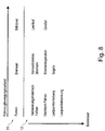
- FIG. 8 lists the possible vehicle movement states 11 of the hybrid vehicle:
- the predefined possible vehicle movement states are, for example, vehicle standstill, brake operation and driving operation (without brakes). As is known, not every one of the operating modes can be realized in each of the possible vehicle movement states 11 of the vehicle.
- a vehicle movement state "driving” is assigned the operating modes of combustion engine driving, electric driving, load point raising and load point lowering.
- the vehicle movement state “brakes” are assigned to the modes conventional braking, brake recovery and sailing.
- the vehicle movement state “standstill” is assigned the operating modes idle and the GenSet.
- step S21 of FIG. 2 First, the current vehicle movement state is determined and then the restriction of the operating modes of the vehicle to those made to the particular current vehicle movement state according to the in FIG. 8 assigned assignment 12 are assigned. Thus, if the vehicle is currently in the vehicle movement state "driving", in the following step S22 only those operating modes are again supplied which are assigned as possible operating modes via the vehicle movement state "driving". The reduced amount of modes 1b is then further processed in step S22.
- step S22 restrictions on individual operating modes are evaluated on the basis of defined rules.
- Restrictions go z. B. from the availability of components.
- Such restrictions may include, for example, thermal restrictions that check whether the electric machine or traction energy storage of the electric machine has become too hot, so that those modes that require the electric machine are not available at the current time and consequently in this Case be excluded from the list of possible operating modes.
- restriction rules can also check if the machine is available for other reasons or not.
- these restrictions are not torque-related, but such criteria are only in the subsequent steps (eg S45, S55), z. For example, within the exclusion criteria.
- the number of possible operating modes 1b can therefore optionally be further restricted in step S22 on the basis of predetermined restriction rules, so that finally a first selection of possible operating modes 1c is supplied to the subsequent two-stage selection process of steps S3 to S5.
- a first selection of possible operating modes 1c is supplied to the subsequent two-stage selection process of steps S3 to S5.
- BA1, BA2 and BA3 three operating modes, which are referred to below as BA1, BA2 and BA3.
- step S3 the in FIG. 2 is not shown, first possible power distributions in the drive train are determined for each of the remaining after the reduction of the operating modes 1c.
- the possible power distribution is given by specifying the torques that can be realized with the electric machine in the current operating state.
- the efficiency of the electric motor is taken into account. From each possible moment of the electric motor, the remaining torque to be applied by the internal combustion engine then results as the difference between the currently requested driver's desired torque minus the torque of the electric motor, so that the power distribution is clearly defined.
- a range of possible values for the E machine torques thus results for each operating mode.
- the possible values for the e-machine torques are calculated in discrete steps, eg. B. in steps of 10 Nm.
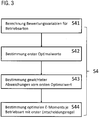
- step S4 then the calculation of the optimal E-machine torque per mode takes place.
- the substeps of step S4 are in the Figures 3 . 5 and 6 each illustrated in different representations.
- the values of the abscissa indicate the possible e-moments determined in step S3 of one of the operating modes of the first selection 1c, here by way of example for the operating mode BA2.
- the operating mode BA2 represents the operating mode of a load point reduction, in which the power required to satisfy the positive driver request torque is provided both by the internal combustion engine and by the electric motor.
- the load point reduction is used for the operating point optimization of the internal combustion engine or for the targeted discharge of the energy store.
- possible E-moments 2 in the range of 0-600 Nm were determined in discrete steps of 10 Nm (see step S3).
- steps S41 and S42 the values of the evaluation variables for each operating mode are then calculated and then the first optimum value is determined for each evaluation variable in the respective operating mode.
- the curves 5 and 6 drawn in the diagram and the horizontal line 7 indicate the course of the values of three evaluation variables calculated in step S41 in dependence on the specific possible moments 2 of the electric motor or the power distribution.
- the curve 5 indicates the course of a rating variable "efficiency of the electric traction machine".
- the unit of this evaluation variable is dimensionless.
- This rating variable is used to quantitatively describe the target criterion of maximizing the energy efficiency of the electric traction machine.
- the target criterion of maximizing the energy efficiency of the electric traction machine is an maximization goal, i. h., energy efficiency should be maximized. Consequently, in step S42, as the first optimum value 5a of the evaluation variable "efficiency of the electric traction machine", the maximum value of the curve 5 is determined.
- the course 5 of this evaluation variable has a maximum 5a at an e-machine torque value of z. B. 100 Nm.
- the efficiency drops again at a larger E-moment than 100 Nm. This is z.
- Example is that the power loss increases quadratically towards higher torques.
- the calculation of the course 5 takes place by means of a stored efficiency map 4a of the electric traction machine.
- the marked with the reference numeral 6 line in the upper diagram of FIG. 6 represents a curve of the battery power and indicates the charging or discharging power of the energy storage, in which the efficiency of the traction energy storage is received.
- the discharge power increases, which is represented by the slope of the curve 6.
- the associated target criterion is a Approxim réellesziel regarding the optimal state of charge of the energy storage, which should be in a predetermined range. If the traction energy store is fully charged, it is favorable to discharge it in order subsequently to again have sufficient storage capacity for receiving recuperation energy. If the traction energy storage heavily discharged, it is convenient to load this again.
- the first optimum value for the course of the curve 6 is given as a desired value 6a as a function of current vehicle data, in particular as a function of the current state of charge of the traction energy store, which is achieved here by a value of the E torque at 440 Nm.
- the course of the curve 7 is the course of a further evaluation variable for the evaluation of another goal.
- This rating variable is an example of a rating variable that is not dependent on the current e-moment.
- the course of such a rating variable shows up as a horizontal straight line above the e-moment and only gains significance in the subsequent step of comparing the different operating modes with one another.
- a minimum is identified as the optimum value. Due to the constant course of the curve 7, this minimum 7a is not associated with a specific torque.
- the first optimal values 5a, 6a, and 7a are determined not only for the mode BA2 but for all modes of the first selection.
- the represented course 5, 6, 7 of the values of the evaluation variables is recalculated each time through the steps S2 to S5.
- the individual calculation steps are here information such as current measurement data, vehicle and component parameters and maps available that are processed by a vehicle controller 4, which is set up to carry out the method, and in the target sizes, exclusion criteria (KO criteria), weighting factors, to be used vehicle parameters, etc. are deposited, which is indicated by the block 4 only by way of example and highly schematic.
- the calculation of the gradients 5, 6, 7 of the evaluation variables takes place as a function of current measured data, vehicle and component parameters as well as characteristic maps and is particularly dependent on the specific drive train configuration of the hybrid vehicle.
- the curves 5, 6, 7 of the evaluation variables thus determined are only valid for one calculation cycle of the steps S2 to S5 of the online calculation, ie. That is, in a subsequent calculation cycle S2 to S5, which is executed a few milliseconds later or in another driving situation, other courses and other optimum values 5a, 6a, 7a may result, since the vehicle parameters and measurement data are constantly changing.
- step S43 for each evaluation variable of each mode, the weighted first deviation of the values of the respective evaluation variable from the determined first optimum value of the respective evaluation variable is determined. This is in the lower diagram of the FIG. 6 shown. To determine the weighted deviation, the difference values from the original curve 5, 6, 7 with the respective optimum value 5a, 6a or 7a are respectively formed for each curve and additionally scaled by a weighting factor (weighting factor).
- weighting factor weighting factor
- the course of the weighted first deviation 5c has a zero point in this torque value of the electric machine.
- the weighted curve 7c is difficult to see in the diagram, since it lies directly on the abscissa axis, which results from the constant curve 7 in the upper diagram. In the present case, this evaluation variable thus virtually disappears from the current evaluation because there is no optimum value.
- the determined first deviations can be translated on the one hand to a dimensionless unit or to a common unit, e.g. a monetary unit of a damage function, because the valuation variables are usually given in different units.
- the weighting makes it possible to calibrate the first deviations of the evaluation variables among one another in order to prioritize the evaluation variables with one another, since as a rule the target criteria assigned to the evaluation variables should be weighted or prioritized to different degrees.
- exclusion criteria in FIG. 5 can be specified as "KO criteria"
- K criteria optional exclusion criteria
- E-moments 9 of the possible power distribution per operating mode are thus excluded, which is indicated by the hatched areas in the lower diagram of the FIG. 6 is shown. In these areas, the values of the evaluation variable or the weighted first deviation are therefore not taken into account in the subsequent determination of the optimum operating mode.
- An advantage of using such exclusion criteria is that they can be determined so that each of the E-moments not excluded thereby already represents an acceptable selection candidate, so that subsequently the optimum of the power distribution is sought only within acceptable power distributions or E-moments , This can reduce the risk of a wrong decision. Furthermore, weaknesses of the subsequently applied decision rules can thereby be compensated, since at least this ensures that an acceptable e-moment is always taken as the basis for the selection of the optimum mode of operation.
- step S44 an optimal E-machine torque 2a is subsequently determined using a predetermined decision rule.
- a preferable solution is therefore a good compromise between all the target criteria.
- a decision rule based on the minimax principle is better suited.
- the curve 10 indicates the worst case in which the greatest first deviation is determined in each case from the values of the weighted first deviations 5c, 6c, 7c at each operating point of the possible moments.
- the optimal power distribution then becomes the E-moment 2 a, to which the smallest 10 a of the determined largest first deviations 10 is assigned. This is the case in point 2a, since the dashed curve has its minimum 10a at the operating point 2a. It should be pointed out again that in FIG.
- step S4 the values of the evaluation variables with the associated optimum values and the weighted deviations from the first optimum values are calculated for all operating modes of the first selection 1c, and then the optimum power distribution for the respective operating mode is determined.
- the upper right diagram again shows the result of step S44 for operating mode BA2. From the possible values 2 of the E machine torques in the operating mode BA2, the point 2a is determined as the optimum E machine torque. At this optimal power distribution operating point 2a, the values 5b, 6b, and 7b are assigned as corresponding values of the evaluation variables, which are subsequently supplied to the step S5
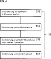
- step S5 the determination of the optimum operating mode then takes place based on the results of step S4.
- the steps S51 to S54 or S55 are performed, which in turn in the FIGS. 4 . 5 and 7 illustrated in different representations.
- step S51 first, the optimum E-moments for each mode and the corresponding values of the evaluation variables 5b, 6b, 7b determined in step S44 are provided as input data, which is shown in the upper diagram of FIG. 7 is exemplified for the three operating modes BA1, BA2 and BA3.
- BA1 a mode of load increase.
- the engine When boosting the load, the engine provides both the power to fully meet the positive driver torque demand and to simultaneously charge traction energy storage.
- the operating mode BA3 represents a mode of purely electric driving.
- steps S52 to S55 correspond in principle to steps S42 to S45.
- the special feature when performing steps S52 to S55 is that the calculation steps are now run through with the optimal power distributions 2a of the operating modes and the associated values 5b, 6b, 7b of the evaluation variables.
- step S52 first the optimal values 5d, 6d, 7d of the evaluation variable are determined again. Whether the respective optimum value is a maximum value, a minimum value or a desired value, in turn, depends on the respective target criterion.
- the maximum value is searched. But this time across all modes of operation, so that in each case the value 5b is determined as the maximum value 5d, which has the largest value in the operating point 2a of the optimal E-moment. In the present case this is the point 5b of the operating mode BA2, since the value 5b of the operating mode BA3 and the operating mode BA 1 is smaller.
- a desired value 6d is specified, which is set as the optimum value.
- the minimum value is searched.
- the value 7b of the height zero of the mode 3 is set as the optimum value.
- the optimum value 5d, 6d, 7d thus determined for each evaluation variable referred to below as the second optimum value, applies to all operating modes BA1, BA2 and BA3 and is used to determine the weighted second deviation which is determined for each evaluation variable in each mode of the first selection in FIG Step S53 is determined.
- the weighted second deviation 5e, 6e, 7e respectively represents a weighted deviation of the second optimum value 5d, 6d, 7d of the respective evaluation variable from the values of the respective evaluation variables 5b, 6b, etc. at the operating point 2a of the determined optimum power distribution for the respective mode.
- a value of 0 for the weighted second deviation 5e results for the operating variable "efficiency of the electric traction machine" since the second optimum value 5b is identical to the value of the evaluation variable for this operating mode.
- a positive difference in the absolute value of the weighted results second deviation 5e.
- the weighted second deviation 7e of the operating mode BA3 results in a value of 0, while the weighted second deviation 7e results in a positive absolute value value for the operating mode BA2.
- step S54 the determination of the optimum operating mode is carried out using a second decision rule according to which the operating modes BA1, BA2 and BA3 are respectively evaluated as a function of the weighted second deviations 5e, 6e and 7e of the evaluation variables and from this an optimum operating mode is determined ,
- the decision rule used is not the previously applied minimax decision rule. Rather, according to the second decision rule, the weighted second deviations 5e, 6e, 7e of the evaluation variables are respectively summed up into a mode of operation, resulting in the points ⁇ 1, ⁇ 2 and ⁇ 3. Subsequently, the smallest of these sum values is determined, which in the present case corresponds to the value ⁇ 2. Then, that mode is set as the optimum mode 3 having the smallest of these sum values. Thus, in the present case, the operating mode BA2 is set as the optimum operating mode.
- the optimum operating mode BA2 which corresponds to a load point reduction, is thus subsequently set by a control device as the current operating mode, wherein the previously determined in this mode optimal power distribution in the form of the optimal e-machine torque in the amount of just over 200 Nm specified as e-machine torque becomes.
Landscapes
- Engineering & Computer Science (AREA)
- Transportation (AREA)
- Mechanical Engineering (AREA)
- Chemical & Material Sciences (AREA)
- Combustion & Propulsion (AREA)
- Automation & Control Theory (AREA)
- Electric Propulsion And Braking For Vehicles (AREA)
- Human Computer Interaction (AREA)
Claims (10)
- Procédé de sélection d'un mode de fonctionnement d'un véhicule hybride, selon lequel un mode de fonctionnement optimal pour l'instant de fonctionnement actuel du point de vue de critères cibles prédéfinis, avec une distribution de puissance optimale correspondante dans le groupe motopropulseur, est sélectionné parmi un nombre prédéfini de modes de fonctionnement possibles (1a) d'un groupe motopropulseur hybride, au moins une variable d'évaluation étant déterminée pour chacun des critères cibles prédéfinis en vue de la description quantitative du critère cible respectif (S1), comprenant les étapes suivantes :- pour chaque mode de fonctionnement d'une première sélection (1c) de modes de fonctionnement possibles, détermination des distributions de puissance possibles (2) dans le groupe motopropulseur (S3) ; et- pour chaque mode de fonctionnement de la première sélection, détermination de valeurs (5, 6, 7) des variables d'évaluation pour chacune des distributions de puissance (2) déterminées du mode de fonctionnement respectif et détermination d'une distribution de puissance optimale (2a) dans le groupe motopropulseur au moyen des valeurs déterminées des variables d'évaluation pour chaque mode de fonctionnement (S4) ; et- sélection d'un mode de fonctionnement optimal au moyen des valeurs des variables d'évaluation qui présentent celles-ci pour les modes de fonctionnement de la première sélection respectivement au point de fonctionnement de la distribution de puissance optimale (S5),
caractérisé en ce
que les étapes suivantes sont exécutées pour chaque mode de fonctionnement de la première sélection en vue de déterminer la distribution de puissance optimale pour chaque mode de fonctionnement de la première sélection (S4) :a) pour chaque variable d'évaluation, détermination d'une première valeur optimale (5a, 6a, 7a) de la variable d'évaluation dans le mode de fonctionnement respectif la première valeur optimale étant de préférence (S42)a1) définie en tant que valeur extrême (5a, 7a) des valeurs déterminées de la variable d'évaluation dans le mode de fonctionnement respectif dans le cas où la cible décrite par la variable d'évaluation est une cible d'extrême, eta2) prédéfinie en tant que valeur de consigne (6a) indépendante des valeurs déterminées de la variable d'évaluation dans le mode de fonctionnement respectif dans le cas où la cible décrite par la variable d'évaluation est une cible approximative ;b) pour chaque variable d'évaluation, détermination de premiers écarts pondérés (5c, 6c, 7c) des valeurs de la variable d'évaluation respective par rapport à la première valeur optimale (5a, 6a, 7a) déterminée de la variable d'évaluation respective (S43) ; etc) détermination de la distribution de puissance optimale du mode de fonctionnement respectif en utilisant une première règle de décision prédéterminée (S44), laquelle définit une distribution de puissance optimale (2a) en fonction des premiers écarts pondérés (5c, 6c, 7c) déterminés des variables d'évaluation (S44) ; et/ou que les étapes suivantes sont exécutées pour sélectionner un mode de fonctionnement optimal à partir de la première sélection des modes de fonctionnement possibles :a) pour chaque variable d'évaluation, détermination d'une deuxième valeur optimale (5d, 6d, 7d) de la variable d'évaluation valide pour tous les modes de fonctionnement de la première sélection, (S52), la deuxième valeur optimale étant de préférencea1) définie en tant que valeur extrême des valeurs (5b, 7b) des variables d'évaluation respectives au point de fonctionnement de la distribution de puissance optimale déterminée dans tous les modes de fonctionnement de la première sélection dans le cas où la cible décrite par la variable d'évaluation est une cible d'extrême, eta2) prédéfinie en tant que valeur de consigne (6d) indépendante des valeurs déterminées (5b, 7b) de la variable d'évaluation respective dans le cas où la cible décrite par la variable d'évaluation est une cible approximative ;b) détermination d'un deuxième écart pondéré (5e, 6e, 7e), qui est déterminé respectivement pour chaque variable d'évaluation dans chaque mode de fonctionnement de la première sélection et qui indique respectivement un écart pondéré entre la deuxième valeur optimale (5d, 6d, 7d) de la variable d'évaluation respective et la valeur des variables d'évaluation au point de fonctionnement (2a) de la distribution de puissance optimale déterminée pour le mode de fonctionnement respectif (S53) ; etc) sélection du mode de fonctionnement optimal en utilisant une deuxième règle de décision prédéterminée, laquelle évalue les modes de fonctionnement de la première sélection respectivement en fonction des deuxièmes écarts pondérés (5e, 6e, 7e) des variables d'évaluation et définit un mode de fonctionnement optimal (BA2) (S54). - Procédé selon la revendication 1, caractérisé par au moins un facteur de pondération pour chaque variable d'évaluation en vue de déterminer lesa) premiers écarts pondérés (5c, 6c, 7c), lequel redimensionne l'amplitude de la différence entre les valeurs des variables d'évaluation et la première valeur optimale de la variable d'évaluation respective sur une base sans dimension ou une base de coût commune à toutes les variables d'évaluation ; et/oub) deuxièmes écarts pondérés (5e, 6e, 7e, 8e), lequel redimensionne l'amplitude de la différence entre les valeurs des variables d'évaluation et la deuxième valeur optimale de la variable d'évaluation respective sur une base sans dimension ou une base de coût commune à toutes les variables d'évaluation.
- Procédé selon la revendication 1 ou 2, caractérisé en cea) que conformément à la deuxième règle de décision, les deuxièmes écarts pondérés (5e, 6e, 7e, 8e) des variables d'évaluation d'un mode de fonctionnement respectif sont additionnés et le mode de fonctionnement qui est défini en tant que mode de fonctionnement optimal est celui dont le total (S2) des deuxièmes écarts additionnés (∑1, ∑2, ∑3) est minimal ; et/oub1) que la première règle de décision est une règle de décision mini/maxi, et/oub2) que conformément à la première règle de décision, le plus grand premier écart (10) est déterminé à chaque point de fonctionnement des distributions de puissance possibles d'un mode de fonctionnement, respectivement à partir des valeurs des premiers écarts pondérés (5c, 6c, 7c) des variables d'évaluation et le point de fonctionnement (2a) qui est défini en tant que distribution de puissance optimale est celui qui présente le plus petit (10a) des plus grands premiers écarts (10) déterminés.
- Procédé selon l'une des revendications précédentes, caractérisé en ce qu'une détermination de la première sélection des modes de fonctionnement comprend les étapes suivantes :a) prédéfinition des états de déplacement de véhicule possibles (11) du véhicule hybride, de modes de fonctionnement possibles du groupe motopropulseur et d'une association (12) qui indique lesquels des modes de fonctionnement possibles sont autorisés dans quel état de déplacement de véhicule ;b) détermination d'un état de déplacement de véhicule actuel ; etc) limitation des modes de fonctionnement du véhicule à ceux qui sont associés à l'état de déplacement de véhicule actuel détermin (S21).
- Procédé selon la revendication 4, caractérisé en ce que la détermination de la première sélection des modes de fonctionnement comprend les étapes suivantes :a) indication d'au moins une règle de restriction qui définit les modes de fonctionnement qui sont actuellement disponibles en fonction d'au moins un paramètre de fonctionnement et indépendamment d'une demande de couple actuelle et de l'état de déplacement de véhicule actuel ; etb) limitation des modes de fonctionnement du véhicule à ceux qui, conformément à l'au moins une règle de restriction, sont actuellement disponibles (S22).
- Procédé selon la revendication 5, caractérisé en ce qu'une disponibilité des composants dans le groupe motopropulseur, notamment d'un accumulateur d'énergie électrique et/ou d'une machine de traction électrique est vérifiée conformément à l'au moins une règle de restriction.
- Procédé selon l'une des revendications précédentes, caractérisé en cea) que des valeurs (9) de la distribution de puissance des modes de fonctionnement qui doivent être exclues en tant que points de fonctionnement possibles sont déterminées à l'aide de critères d'exclusion prédéfinis, etb) qu'en vue de la détermination de la distribution de puissance optimale pour chaque mode de fonctionnement de la première sélection, seules sont utilisées les valeurs de la distribution de puissance possible et les valeurs respectivement associées des variables d'évaluation qui n'ont pas été exclues au moyen des critères d'exclusion (S45) .
- Procédé selon l'une des revendications précédentes, caractérisé en cea) que le véhicule est un véhicule hybride parallèle ; etb) que les distributions de puissance possibles dans le groupe motopropulseur pour chaque mode de fonctionnement sont déterminées en tant que couples pouvant être produits par la machine de traction électrique en tenant compte des performances des composants dans le groupe motopropulseur ; etc) que la distribution de puissance optimale est déterminée par un couple (2a) de la machine de traction électrique qui est optimal du point de vue des critères cibles prédéfinis.
- Procédé selon l'une des revendications précédentes, caractérisé en ce que les modes de fonctionnement possibles du groupe motopropulseur comprennent au moins certains des modes de fonctionnement suivants : déplacement purement par moteur à combustion, déplacement purement électrique avec moteur à combustion interne arrêté, déplacement électrique avec moteur à combustion interne au ralenti, mode suralimentation, récupération de freinage, démarrage électrique, élévation du point de charge, abaissement du point de charge et mode dit en groupe électrogène.
- Véhicule hybride, notamment véhicule utilitaire, comprenant un dispositif de commande destiné à sélectionner un mode de fonctionnement du véhicule hybride, lequel est conçu pour mettre en oeuvre le procédé selon l'une des revendications 1 à 9.
Applications Claiming Priority (1)
| Application Number | Priority Date | Filing Date | Title |
|---|---|---|---|
| DE102015006820.2A DE102015006820A1 (de) | 2015-05-22 | 2015-05-22 | Verfahren zur Auswahl einer Betriebsart eines Hybridfahrzeugs |
Publications (3)
| Publication Number | Publication Date |
|---|---|
| EP3095656A2 EP3095656A2 (fr) | 2016-11-23 |
| EP3095656A3 EP3095656A3 (fr) | 2016-12-14 |
| EP3095656B1 true EP3095656B1 (fr) | 2019-06-05 |
Family
ID=55854542
Family Applications (1)
| Application Number | Title | Priority Date | Filing Date |
|---|---|---|---|
| EP16000919.7A Active EP3095656B1 (fr) | 2015-05-22 | 2016-04-22 | Procede de selection d'un mode de fonctionnement d'un vehicule automobile hybride |
Country Status (6)
| Country | Link |
|---|---|
| US (1) | US10166965B2 (fr) |
| EP (1) | EP3095656B1 (fr) |
| CN (1) | CN106167019B (fr) |
| BR (1) | BR102016010922B1 (fr) |
| DE (1) | DE102015006820A1 (fr) |
| RU (1) | RU2709367C2 (fr) |
Families Citing this family (7)
| Publication number | Priority date | Publication date | Assignee | Title |
|---|---|---|---|---|
| CN106427990B (zh) * | 2016-12-16 | 2018-09-28 | 上汽大众汽车有限公司 | 混合动力系统及其能量管理方法 |
| US20180204252A1 (en) * | 2017-01-19 | 2018-07-19 | Conduent Business Services, Llc | System and method for representing the costs of commuting journeys |
| CN113715800B (zh) * | 2020-05-22 | 2024-06-28 | 广州汽车集团股份有限公司 | 具有混合动力耦合系统的车辆的控制器、控制方法和车辆 |
| CN111891109B (zh) * | 2020-08-12 | 2021-08-03 | 北京理工大学 | 基于非合作博弈论的混合动力汽车能量优化分配控制方法 |
| CN113627693A (zh) * | 2021-01-18 | 2021-11-09 | 吉林大学 | 一种电动汽车实时能量管理方法、装置、汽车和存储介质 |
| IT202100003203A1 (it) * | 2021-02-12 | 2022-08-12 | Punch Hydrocells S R L | Strategia di controllo di un sistema a propulsione ibrida |
| CN114179781B (zh) * | 2021-12-22 | 2022-11-18 | 北京理工大学 | 一种插电式混合动力汽车实时控制优化方法及系统 |
Family Cites Families (11)
| Publication number | Priority date | Publication date | Assignee | Title |
|---|---|---|---|---|
| AT9756U1 (de) * | 2006-12-11 | 2008-03-15 | Magna Steyr Fahrzeugtechnik Ag | Verfahren zur steuerung des hybridantriebes eines kraftfahrzeuges und steuersystem |
| DE102007019989A1 (de) * | 2007-04-27 | 2008-10-30 | Robert Bosch Gmbh | Verfahren zum Betreiben eines Hybridantriebs |
| FR2935123B1 (fr) | 2008-08-20 | 2010-08-27 | Renault Sas | Systeme de commande d'un groupe motopropulseur hybride pour vehicule automobile, et procede associe |
| DE102008042781B4 (de) * | 2008-10-13 | 2019-03-14 | Robert Bosch Gmbh | Bestimmung einer Betriebsart einer Hybridantriebsvorrichtung eines Kraftfahrzeugs |
| RU2480348C2 (ru) * | 2008-12-22 | 2013-04-27 | Тойота Дзидося Кабусики Кайся | Гибридное транспортное средство |
| DE102010008695A1 (de) | 2010-02-19 | 2011-08-25 | FEV Motorentechnik GmbH, 52078 | Steuergerät und Verfahren zur Steuerung eines Betriebspunktes eines hybriden Antriebssystems |
| JP5742124B2 (ja) * | 2010-07-21 | 2015-07-01 | 日産自動車株式会社 | ハイブリッド車両の制御装置 |
| FR3001427B1 (fr) | 2013-01-31 | 2016-01-22 | Renault Sas | Procede de limitation energetique du couple d'assistance a l'acceleration d'un vehicule hybride |
| US9499159B2 (en) * | 2013-08-19 | 2016-11-22 | Denso Corporation | Vehicle control apparatus |
| GB2517469A (en) * | 2013-08-21 | 2015-02-25 | Jaguar Land Rover Ltd | Hybrid electric vehicle controller and method |
| US9409563B2 (en) * | 2013-10-31 | 2016-08-09 | Ford Global Technologies, Llc | PHEV energy management control with trip-oriented energy consumption preplanning |
-
2015
- 2015-05-22 DE DE102015006820.2A patent/DE102015006820A1/de not_active Withdrawn
-
2016
- 2016-04-22 EP EP16000919.7A patent/EP3095656B1/fr active Active
- 2016-05-13 BR BR102016010922-1A patent/BR102016010922B1/pt active IP Right Grant
- 2016-05-20 RU RU2016119516A patent/RU2709367C2/ru active
- 2016-05-20 CN CN201610336593.8A patent/CN106167019B/zh active Active
- 2016-05-23 US US15/162,031 patent/US10166965B2/en active Active
Non-Patent Citations (1)
| Title |
|---|
| None * |
Also Published As
| Publication number | Publication date |
|---|---|
| EP3095656A2 (fr) | 2016-11-23 |
| DE102015006820A1 (de) | 2016-11-24 |
| BR102016010922B1 (pt) | 2022-10-04 |
| US10166965B2 (en) | 2019-01-01 |
| CN106167019B (zh) | 2020-09-25 |
| BR102016010922A2 (pt) | 2016-11-22 |
| RU2709367C2 (ru) | 2019-12-17 |
| CN106167019A (zh) | 2016-11-30 |
| RU2016119516A (ru) | 2017-11-23 |
| RU2016119516A3 (fr) | 2019-10-10 |
| US20160339904A1 (en) | 2016-11-24 |
| EP3095656A3 (fr) | 2016-12-14 |
| BR102016010922A8 (pt) | 2021-10-13 |
Similar Documents
| Publication | Publication Date | Title |
|---|---|---|
| EP3095656B1 (fr) | Procede de selection d'un mode de fonctionnement d'un vehicule automobile hybride | |
| EP3106362B1 (fr) | Procede d'adaptation en ligne d'une courbe caracteristique d'un vehicule hybride | |
| EP2097304B1 (fr) | Procédé de commande de l'entraînement hybride d'un véhicule automobile, et système de commande | |
| DE102014012318B4 (de) | Verfahren zum Vorausberechnen eines Verbrauchs eines Kraftfahrzeugs, Kraftfahrzeug und Computerprogramm | |
| DE102015223045A1 (de) | Ladesteuerverfahren und System für ein elektrisches Fahrzeug | |
| EP3173284A1 (fr) | Procede de fonctionnement d'une pile a combustible | |
| EP2857271A2 (fr) | Procédé de fonctionnement d'un entraînement hybride, notamment pour la sélection de modes de fonctionnement optimaux de l'entraînement hybride le long d'un trajet | |
| DE102010029122A1 (de) | Regelabgleichverfahren des Ladungszustandes einer Batterie für ein Hybridfahrzeug | |
| DE102014204354A1 (de) | Verfahren zum Betreiben eines Fahrzeugs und Fahrerassistenzsystem | |
| DE102015226614A1 (de) | Verfahren zum Betreiben eines Kraftfahrzeugs, Steuerungseinheit für ein Antriebssystem und ein Antriebssystem | |
| DE102018124515A1 (de) | Autonomes Fahrzeugbeschleunigungsprofil | |
| DE102013222751A1 (de) | System und Verfahren zum Steuern des Fahrmodus eines Hybridfahrzeugs | |
| DE102019217299A1 (de) | Verfahren zur Prädiktion eines Alterungszustands einer Batterie | |
| DE102021204510A1 (de) | Verfahren und Antriebssystem zur Anpassung einer Antriebsunterstützung durch einen elektrischen Antriebsmotor eines elektrisch antreibbaren Fahrrades | |
| DE102015225296B4 (de) | System und Verfahren zum Regeln der LDC-Spannung eines Hybridfahrzeugs | |
| EP3072769B1 (fr) | Procede destine a limiter l'espace de recherche d'un procede d'optimisation en ligne par modelisation destine a predire une variable d'un vehicule automobile | |
| EP3988361A1 (fr) | Procédé de fonctionnement d'un véhicule doté d'un système de transmission hybride | |
| DE102017123033A1 (de) | System und verfahren zum steuern von elektrofahrzeugen | |
| DE102019114617A1 (de) | Voraussagendes drehmomentmanagement für antriebsstrang mit kontinuierlichen stellgliedern und mehreren diskreten modi | |
| DE102019117737A1 (de) | Brennstoffzellensystem | |
| DE102014219216A1 (de) | Verfahren und Vorrichtung zum vorausschauenden Betreiben eines Kraftfahrzeugs | |
| DE102012202284B4 (de) | Vorausschauendes Energiemanagement | |
| DE102023120726A1 (de) | Globale Koordinierung der Energieverteilung an Teilsysteme in BEV | |
| DE102018205238A1 (de) | Verfahren zum Durchführen eines Umschaltvorgangs in einem Hybridfahrzeug, Motorsteuerung und Hybridfahrzeug | |
| DE102017204163A1 (de) | Verfahren zum Betreiben eines Kraftfahrzeugs mit einem hybriden Antriebssystem sowie Steuereinrichtung für ein Antriebssystem sowie ein Antriebssystem |
Legal Events
| Date | Code | Title | Description |
|---|---|---|---|
| PUAI | Public reference made under article 153(3) epc to a published international application that has entered the european phase |
Free format text: ORIGINAL CODE: 0009012 |
|
| PUAL | Search report despatched |
Free format text: ORIGINAL CODE: 0009013 |
|
| AK | Designated contracting states |
Kind code of ref document: A2 Designated state(s): AL AT BE BG CH CY CZ DE DK EE ES FI FR GB GR HR HU IE IS IT LI LT LU LV MC MK MT NL NO PL PT RO RS SE SI SK SM TR |
|
| AX | Request for extension of the european patent |
Extension state: BA ME |
|
| AK | Designated contracting states |
Kind code of ref document: A3 Designated state(s): AL AT BE BG CH CY CZ DE DK EE ES FI FR GB GR HR HU IE IS IT LI LT LU LV MC MK MT NL NO PL PT RO RS SE SI SK SM TR |
|
| AX | Request for extension of the european patent |
Extension state: BA ME |
|
| RIC1 | Information provided on ipc code assigned before grant |
Ipc: B60W 20/40 20160101ALI20161107BHEP Ipc: B60W 10/08 20060101AFI20161107BHEP |
|
| STAA | Information on the status of an ep patent application or granted ep patent |
Free format text: STATUS: REQUEST FOR EXAMINATION WAS MADE |
|
| 17P | Request for examination filed |
Effective date: 20170608 |
|
| RBV | Designated contracting states (corrected) |
Designated state(s): AL AT BE BG CH CY CZ DE DK EE ES FI FR GB GR HR HU IE IS IT LI LT LU LV MC MK MT NL NO PL PT RO RS SE SI SK SM TR |
|
| GRAP | Despatch of communication of intention to grant a patent |
Free format text: ORIGINAL CODE: EPIDOSNIGR1 |
|
| STAA | Information on the status of an ep patent application or granted ep patent |
Free format text: STATUS: GRANT OF PATENT IS INTENDED |
|
| INTG | Intention to grant announced |
Effective date: 20181212 |
|
| GRAS | Grant fee paid |
Free format text: ORIGINAL CODE: EPIDOSNIGR3 |
|
| RIN1 | Information on inventor provided before grant (corrected) |
Inventor name: KIRCHENSTEINER, ELMAR Inventor name: HIERLMEIER, MATTHIAS Inventor name: OVARI, SEBASTIAN Inventor name: GUENNEWICHT, MANUEL Inventor name: NUBER, JOHANNES |
|
| GRAA | (expected) grant |
Free format text: ORIGINAL CODE: 0009210 |
|
| STAA | Information on the status of an ep patent application or granted ep patent |
Free format text: STATUS: THE PATENT HAS BEEN GRANTED |
|
| AK | Designated contracting states |
Kind code of ref document: B1 Designated state(s): AL AT BE BG CH CY CZ DE DK EE ES FI FR GB GR HR HU IE IS IT LI LT LU LV MC MK MT NL NO PL PT RO RS SE SI SK SM TR |
|
| REG | Reference to a national code |
Ref country code: GB Ref legal event code: FG4D Free format text: NOT ENGLISH |
|
| REG | Reference to a national code |
Ref country code: CH Ref legal event code: EP |
|
| REG | Reference to a national code |
Ref country code: AT Ref legal event code: REF Ref document number: 1139679 Country of ref document: AT Kind code of ref document: T Effective date: 20190615 |
|
| REG | Reference to a national code |
Ref country code: IE Ref legal event code: FG4D Free format text: LANGUAGE OF EP DOCUMENT: GERMAN |
|
| REG | Reference to a national code |
Ref country code: DE Ref legal event code: R096 Ref document number: 502016004868 Country of ref document: DE |
|
| RAP2 | Party data changed (patent owner data changed or rights of a patent transferred) |
Owner name: MAN TRUCK & BUS SE |
|
| REG | Reference to a national code |
Ref country code: NL Ref legal event code: FP |
|
| REG | Reference to a national code |
Ref country code: SE Ref legal event code: TRGR |
|
| REG | Reference to a national code |
Ref country code: DE Ref legal event code: R081 Ref document number: 502016004868 Country of ref document: DE Owner name: MAN TRUCK & BUS SE, DE Free format text: FORMER OWNER: MAN TRUCK & BUS AG, 80995 MUENCHEN, DE |
|
| REG | Reference to a national code |
Ref country code: LT Ref legal event code: MG4D |
|
| PG25 | Lapsed in a contracting state [announced via postgrant information from national office to epo] |
Ref country code: FI Free format text: LAPSE BECAUSE OF FAILURE TO SUBMIT A TRANSLATION OF THE DESCRIPTION OR TO PAY THE FEE WITHIN THE PRESCRIBED TIME-LIMIT Effective date: 20190605 Ref country code: NO Free format text: LAPSE BECAUSE OF FAILURE TO SUBMIT A TRANSLATION OF THE DESCRIPTION OR TO PAY THE FEE WITHIN THE PRESCRIBED TIME-LIMIT Effective date: 20190905 Ref country code: AL Free format text: LAPSE BECAUSE OF FAILURE TO SUBMIT A TRANSLATION OF THE DESCRIPTION OR TO PAY THE FEE WITHIN THE PRESCRIBED TIME-LIMIT Effective date: 20190605 Ref country code: HR Free format text: LAPSE BECAUSE OF FAILURE TO SUBMIT A TRANSLATION OF THE DESCRIPTION OR TO PAY THE FEE WITHIN THE PRESCRIBED TIME-LIMIT Effective date: 20190605 Ref country code: LT Free format text: LAPSE BECAUSE OF FAILURE TO SUBMIT A TRANSLATION OF THE DESCRIPTION OR TO PAY THE FEE WITHIN THE PRESCRIBED TIME-LIMIT Effective date: 20190605 Ref country code: ES Free format text: LAPSE BECAUSE OF FAILURE TO SUBMIT A TRANSLATION OF THE DESCRIPTION OR TO PAY THE FEE WITHIN THE PRESCRIBED TIME-LIMIT Effective date: 20190605 |
|
| PG25 | Lapsed in a contracting state [announced via postgrant information from national office to epo] |
Ref country code: LV Free format text: LAPSE BECAUSE OF FAILURE TO SUBMIT A TRANSLATION OF THE DESCRIPTION OR TO PAY THE FEE WITHIN THE PRESCRIBED TIME-LIMIT Effective date: 20190605 Ref country code: RS Free format text: LAPSE BECAUSE OF FAILURE TO SUBMIT A TRANSLATION OF THE DESCRIPTION OR TO PAY THE FEE WITHIN THE PRESCRIBED TIME-LIMIT Effective date: 20190605 Ref country code: BG Free format text: LAPSE BECAUSE OF FAILURE TO SUBMIT A TRANSLATION OF THE DESCRIPTION OR TO PAY THE FEE WITHIN THE PRESCRIBED TIME-LIMIT Effective date: 20190905 Ref country code: GR Free format text: LAPSE BECAUSE OF FAILURE TO SUBMIT A TRANSLATION OF THE DESCRIPTION OR TO PAY THE FEE WITHIN THE PRESCRIBED TIME-LIMIT Effective date: 20190906 |
|
| PG25 | Lapsed in a contracting state [announced via postgrant information from national office to epo] |
Ref country code: CZ Free format text: LAPSE BECAUSE OF FAILURE TO SUBMIT A TRANSLATION OF THE DESCRIPTION OR TO PAY THE FEE WITHIN THE PRESCRIBED TIME-LIMIT Effective date: 20190605 Ref country code: RO Free format text: LAPSE BECAUSE OF FAILURE TO SUBMIT A TRANSLATION OF THE DESCRIPTION OR TO PAY THE FEE WITHIN THE PRESCRIBED TIME-LIMIT Effective date: 20190605 Ref country code: EE Free format text: LAPSE BECAUSE OF FAILURE TO SUBMIT A TRANSLATION OF THE DESCRIPTION OR TO PAY THE FEE WITHIN THE PRESCRIBED TIME-LIMIT Effective date: 20190605 Ref country code: SK Free format text: LAPSE BECAUSE OF FAILURE TO SUBMIT A TRANSLATION OF THE DESCRIPTION OR TO PAY THE FEE WITHIN THE PRESCRIBED TIME-LIMIT Effective date: 20190605 Ref country code: PT Free format text: LAPSE BECAUSE OF FAILURE TO SUBMIT A TRANSLATION OF THE DESCRIPTION OR TO PAY THE FEE WITHIN THE PRESCRIBED TIME-LIMIT Effective date: 20191007 |
|
| PG25 | Lapsed in a contracting state [announced via postgrant information from national office to epo] |
Ref country code: IS Free format text: LAPSE BECAUSE OF FAILURE TO SUBMIT A TRANSLATION OF THE DESCRIPTION OR TO PAY THE FEE WITHIN THE PRESCRIBED TIME-LIMIT Effective date: 20191005 Ref country code: SM Free format text: LAPSE BECAUSE OF FAILURE TO SUBMIT A TRANSLATION OF THE DESCRIPTION OR TO PAY THE FEE WITHIN THE PRESCRIBED TIME-LIMIT Effective date: 20190605 |
|
| REG | Reference to a national code |
Ref country code: DE Ref legal event code: R097 Ref document number: 502016004868 Country of ref document: DE |
|
| PG25 | Lapsed in a contracting state [announced via postgrant information from national office to epo] |
Ref country code: TR Free format text: LAPSE BECAUSE OF FAILURE TO SUBMIT A TRANSLATION OF THE DESCRIPTION OR TO PAY THE FEE WITHIN THE PRESCRIBED TIME-LIMIT Effective date: 20190605 |
|
| PLBE | No opposition filed within time limit |
Free format text: ORIGINAL CODE: 0009261 |
|
| STAA | Information on the status of an ep patent application or granted ep patent |
Free format text: STATUS: NO OPPOSITION FILED WITHIN TIME LIMIT |
|
| PG25 | Lapsed in a contracting state [announced via postgrant information from national office to epo] |
Ref country code: DK Free format text: LAPSE BECAUSE OF FAILURE TO SUBMIT A TRANSLATION OF THE DESCRIPTION OR TO PAY THE FEE WITHIN THE PRESCRIBED TIME-LIMIT Effective date: 20190605 Ref country code: PL Free format text: LAPSE BECAUSE OF FAILURE TO SUBMIT A TRANSLATION OF THE DESCRIPTION OR TO PAY THE FEE WITHIN THE PRESCRIBED TIME-LIMIT Effective date: 20190605 |
|
| 26N | No opposition filed |
Effective date: 20200306 |
|
| PG25 | Lapsed in a contracting state [announced via postgrant information from national office to epo] |
Ref country code: SI Free format text: LAPSE BECAUSE OF FAILURE TO SUBMIT A TRANSLATION OF THE DESCRIPTION OR TO PAY THE FEE WITHIN THE PRESCRIBED TIME-LIMIT Effective date: 20190605 |
|
| PG25 | Lapsed in a contracting state [announced via postgrant information from national office to epo] |
Ref country code: MC Free format text: LAPSE BECAUSE OF FAILURE TO SUBMIT A TRANSLATION OF THE DESCRIPTION OR TO PAY THE FEE WITHIN THE PRESCRIBED TIME-LIMIT Effective date: 20190605 |
|
| REG | Reference to a national code |
Ref country code: CH Ref legal event code: PL |
|
| PG25 | Lapsed in a contracting state [announced via postgrant information from national office to epo] |
Ref country code: CH Free format text: LAPSE BECAUSE OF NON-PAYMENT OF DUE FEES Effective date: 20200430 Ref country code: LI Free format text: LAPSE BECAUSE OF NON-PAYMENT OF DUE FEES Effective date: 20200430 Ref country code: LU Free format text: LAPSE BECAUSE OF NON-PAYMENT OF DUE FEES Effective date: 20200422 |
|
| REG | Reference to a national code |
Ref country code: BE Ref legal event code: MM Effective date: 20200430 |
|
| PG25 | Lapsed in a contracting state [announced via postgrant information from national office to epo] |
Ref country code: BE Free format text: LAPSE BECAUSE OF NON-PAYMENT OF DUE FEES Effective date: 20200430 |
|
| GBPC | Gb: european patent ceased through non-payment of renewal fee |
Effective date: 20200422 |
|
| PG25 | Lapsed in a contracting state [announced via postgrant information from national office to epo] |
Ref country code: IE Free format text: LAPSE BECAUSE OF NON-PAYMENT OF DUE FEES Effective date: 20200422 Ref country code: GB Free format text: LAPSE BECAUSE OF NON-PAYMENT OF DUE FEES Effective date: 20200422 |
|
| PG25 | Lapsed in a contracting state [announced via postgrant information from national office to epo] |
Ref country code: MT Free format text: LAPSE BECAUSE OF FAILURE TO SUBMIT A TRANSLATION OF THE DESCRIPTION OR TO PAY THE FEE WITHIN THE PRESCRIBED TIME-LIMIT Effective date: 20190605 Ref country code: CY Free format text: LAPSE BECAUSE OF FAILURE TO SUBMIT A TRANSLATION OF THE DESCRIPTION OR TO PAY THE FEE WITHIN THE PRESCRIBED TIME-LIMIT Effective date: 20190605 |
|
| REG | Reference to a national code |
Ref country code: AT Ref legal event code: MM01 Ref document number: 1139679 Country of ref document: AT Kind code of ref document: T Effective date: 20210422 |
|
| PG25 | Lapsed in a contracting state [announced via postgrant information from national office to epo] |
Ref country code: MK Free format text: LAPSE BECAUSE OF FAILURE TO SUBMIT A TRANSLATION OF THE DESCRIPTION OR TO PAY THE FEE WITHIN THE PRESCRIBED TIME-LIMIT Effective date: 20190605 |
|
| PG25 | Lapsed in a contracting state [announced via postgrant information from national office to epo] |
Ref country code: AT Free format text: LAPSE BECAUSE OF NON-PAYMENT OF DUE FEES Effective date: 20210422 |
|
| PGFP | Annual fee paid to national office [announced via postgrant information from national office to epo] |
Ref country code: NL Payment date: 20250424 Year of fee payment: 10 |
|
| PGFP | Annual fee paid to national office [announced via postgrant information from national office to epo] |
Ref country code: DE Payment date: 20250428 Year of fee payment: 10 |
|
| PGFP | Annual fee paid to national office [announced via postgrant information from national office to epo] |
Ref country code: IT Payment date: 20250422 Year of fee payment: 10 |
|
| PGFP | Annual fee paid to national office [announced via postgrant information from national office to epo] |
Ref country code: FR Payment date: 20250424 Year of fee payment: 10 |
|
| PGFP | Annual fee paid to national office [announced via postgrant information from national office to epo] |
Ref country code: SE Payment date: 20250424 Year of fee payment: 10 |