EP3095400B1 - Wirbelsäulenfixierungskonstrukt - Google Patents
Wirbelsäulenfixierungskonstrukt Download PDFInfo
- Publication number
- EP3095400B1 EP3095400B1 EP16173488.4A EP16173488A EP3095400B1 EP 3095400 B1 EP3095400 B1 EP 3095400B1 EP 16173488 A EP16173488 A EP 16173488A EP 3095400 B1 EP3095400 B1 EP 3095400B1
- Authority
- EP
- European Patent Office
- Prior art keywords
- spinal
- flexible member
- modulus
- elasticity
- fixation
- Prior art date
- Legal status (The legal status is an assumption and is not a legal conclusion. Google has not performed a legal analysis and makes no representation as to the accuracy of the status listed.)
- Active
Links
- 210000000988 bone and bone Anatomy 0.000 claims description 50
- 239000000463 material Substances 0.000 claims description 18
- 238000000034 method Methods 0.000 description 19
- 239000007943 implant Substances 0.000 description 16
- 238000001356 surgical procedure Methods 0.000 description 8
- -1 but not limited to Substances 0.000 description 4
- 238000011065 in-situ storage Methods 0.000 description 4
- 210000000115 thoracic cavity Anatomy 0.000 description 4
- 206010023509 Kyphosis Diseases 0.000 description 3
- 238000011282 treatment Methods 0.000 description 3
- 229910000684 Cobalt-chrome Inorganic materials 0.000 description 2
- 208000007623 Lordosis Diseases 0.000 description 2
- 229910001069 Ti alloy Inorganic materials 0.000 description 2
- 239000000560 biocompatible material Substances 0.000 description 2
- 239000010952 cobalt-chrome Substances 0.000 description 2
- 208000037265 diseases, disorders, signs and symptoms Diseases 0.000 description 2
- 230000004927 fusion Effects 0.000 description 2
- 239000007769 metal material Substances 0.000 description 2
- 125000006850 spacer group Chemical group 0.000 description 2
- 210000000278 spinal cord Anatomy 0.000 description 2
- 239000010935 stainless steel Substances 0.000 description 2
- 208000024891 symptom Diseases 0.000 description 2
- 230000007704 transition Effects 0.000 description 2
- 206010061246 Intervertebral disc degeneration Diseases 0.000 description 1
- 208000034819 Mobility Limitation Diseases 0.000 description 1
- 206010028980 Neoplasm Diseases 0.000 description 1
- 239000004677 Nylon Substances 0.000 description 1
- 208000001132 Osteoporosis Diseases 0.000 description 1
- 229930182556 Polyacetal Natural products 0.000 description 1
- 239000004697 Polyetherimide Substances 0.000 description 1
- 239000004698 Polyethylene Substances 0.000 description 1
- 239000004743 Polypropylene Substances 0.000 description 1
- 206010058907 Spinal deformity Diseases 0.000 description 1
- 208000020307 Spinal disease Diseases 0.000 description 1
- 208000020339 Spinal injury Diseases 0.000 description 1
- 208000007103 Spondylolisthesis Diseases 0.000 description 1
- 239000004699 Ultra-high molecular weight polyethylene Substances 0.000 description 1
- 208000027418 Wounds and injury Diseases 0.000 description 1
- 230000037182 bone density Effects 0.000 description 1
- 239000002775 capsule Substances 0.000 description 1
- 230000000295 complement effect Effects 0.000 description 1
- 239000002131 composite material Substances 0.000 description 1
- 238000000748 compression moulding Methods 0.000 description 1
- 210000002808 connective tissue Anatomy 0.000 description 1
- 238000010276 construction Methods 0.000 description 1
- 230000006378 damage Effects 0.000 description 1
- 230000007850 degeneration Effects 0.000 description 1
- 208000018180 degenerative disc disease Diseases 0.000 description 1
- 230000001419 dependent effect Effects 0.000 description 1
- 230000003292 diminished effect Effects 0.000 description 1
- 201000010099 disease Diseases 0.000 description 1
- 208000035475 disorder Diseases 0.000 description 1
- 238000002224 dissection Methods 0.000 description 1
- 238000002513 implantation Methods 0.000 description 1
- 238000001746 injection moulding Methods 0.000 description 1
- 208000014674 injury Diseases 0.000 description 1
- 208000021600 intervertebral disc degenerative disease Diseases 0.000 description 1
- 210000000281 joint capsule Anatomy 0.000 description 1
- 238000003754 machining Methods 0.000 description 1
- 238000012423 maintenance Methods 0.000 description 1
- 239000002184 metal Substances 0.000 description 1
- 229910052751 metal Inorganic materials 0.000 description 1
- 210000003205 muscle Anatomy 0.000 description 1
- 210000005036 nerve Anatomy 0.000 description 1
- 210000000653 nervous system Anatomy 0.000 description 1
- 230000007971 neurological deficit Effects 0.000 description 1
- 229920001778 nylon Polymers 0.000 description 1
- 230000007170 pathology Effects 0.000 description 1
- 229920002492 poly(sulfone) Polymers 0.000 description 1
- 229920001601 polyetherimide Polymers 0.000 description 1
- 229920000573 polyethylene Polymers 0.000 description 1
- 229920006324 polyoxymethylene Polymers 0.000 description 1
- 229920001155 polypropylene Polymers 0.000 description 1
- 229920001343 polytetrafluoroethylene Polymers 0.000 description 1
- 239000004810 polytetrafluoroethylene Substances 0.000 description 1
- 206010039722 scoliosis Diseases 0.000 description 1
- 238000007493 shaping process Methods 0.000 description 1
- 210000004872 soft tissue Anatomy 0.000 description 1
- 239000007787 solid Substances 0.000 description 1
- 210000001032 spinal nerve Anatomy 0.000 description 1
- 230000000087 stabilizing effect Effects 0.000 description 1
- 229910001220 stainless steel Inorganic materials 0.000 description 1
- 229910001256 stainless steel alloy Inorganic materials 0.000 description 1
- 239000013589 supplement Substances 0.000 description 1
- 229920000785 ultra high molecular weight polyethylene Polymers 0.000 description 1
- 210000002517 zygapophyseal joint Anatomy 0.000 description 1
Images


Classifications
-
- A—HUMAN NECESSITIES
- A61—MEDICAL OR VETERINARY SCIENCE; HYGIENE
- A61B—DIAGNOSIS; SURGERY; IDENTIFICATION
- A61B17/00—Surgical instruments, devices or methods, e.g. tourniquets
- A61B17/56—Surgical instruments or methods for treatment of bones or joints; Devices specially adapted therefor
- A61B17/58—Surgical instruments or methods for treatment of bones or joints; Devices specially adapted therefor for osteosynthesis, e.g. bone plates, screws, setting implements or the like
- A61B17/68—Internal fixation devices, including fasteners and spinal fixators, even if a part thereof projects from the skin
- A61B17/70—Spinal positioners or stabilisers ; Bone stabilisers comprising fluid filler in an implant
- A61B17/7001—Screws or hooks combined with longitudinal elements which do not contact vertebrae
- A61B17/7002—Longitudinal elements, e.g. rods
- A61B17/7019—Longitudinal elements having flexible parts, or parts connected together, such that after implantation the elements can move relative to each other
- A61B17/7031—Longitudinal elements having flexible parts, or parts connected together, such that after implantation the elements can move relative to each other made wholly or partly of flexible material
-
- A—HUMAN NECESSITIES
- A61—MEDICAL OR VETERINARY SCIENCE; HYGIENE
- A61B—DIAGNOSIS; SURGERY; IDENTIFICATION
- A61B17/00—Surgical instruments, devices or methods, e.g. tourniquets
- A61B17/56—Surgical instruments or methods for treatment of bones or joints; Devices specially adapted therefor
- A61B17/58—Surgical instruments or methods for treatment of bones or joints; Devices specially adapted therefor for osteosynthesis, e.g. bone plates, screws, setting implements or the like
- A61B17/68—Internal fixation devices, including fasteners and spinal fixators, even if a part thereof projects from the skin
- A61B17/70—Spinal positioners or stabilisers ; Bone stabilisers comprising fluid filler in an implant
- A61B17/7001—Screws or hooks combined with longitudinal elements which do not contact vertebrae
- A61B17/7002—Longitudinal elements, e.g. rods
- A61B17/7004—Longitudinal elements, e.g. rods with a cross-section which varies along its length
-
- A—HUMAN NECESSITIES
- A61—MEDICAL OR VETERINARY SCIENCE; HYGIENE
- A61B—DIAGNOSIS; SURGERY; IDENTIFICATION
- A61B17/00—Surgical instruments, devices or methods, e.g. tourniquets
- A61B17/56—Surgical instruments or methods for treatment of bones or joints; Devices specially adapted therefor
- A61B17/58—Surgical instruments or methods for treatment of bones or joints; Devices specially adapted therefor for osteosynthesis, e.g. bone plates, screws, setting implements or the like
- A61B17/68—Internal fixation devices, including fasteners and spinal fixators, even if a part thereof projects from the skin
- A61B17/70—Spinal positioners or stabilisers ; Bone stabilisers comprising fluid filler in an implant
- A61B17/7001—Screws or hooks combined with longitudinal elements which do not contact vertebrae
- A61B17/7002—Longitudinal elements, e.g. rods
- A61B17/701—Longitudinal elements with a non-circular, e.g. rectangular, cross-section
-
- A—HUMAN NECESSITIES
- A61—MEDICAL OR VETERINARY SCIENCE; HYGIENE
- A61B—DIAGNOSIS; SURGERY; IDENTIFICATION
- A61B17/00—Surgical instruments, devices or methods, e.g. tourniquets
- A61B17/56—Surgical instruments or methods for treatment of bones or joints; Devices specially adapted therefor
- A61B17/58—Surgical instruments or methods for treatment of bones or joints; Devices specially adapted therefor for osteosynthesis, e.g. bone plates, screws, setting implements or the like
- A61B17/68—Internal fixation devices, including fasteners and spinal fixators, even if a part thereof projects from the skin
- A61B17/70—Spinal positioners or stabilisers ; Bone stabilisers comprising fluid filler in an implant
- A61B17/7001—Screws or hooks combined with longitudinal elements which do not contact vertebrae
- A61B17/7002—Longitudinal elements, e.g. rods
- A61B17/7019—Longitudinal elements having flexible parts, or parts connected together, such that after implantation the elements can move relative to each other
- A61B17/7022—Tethers, i.e. longitudinal elements capable of transmitting tension only, e.g. straps, sutures or cables
-
- A—HUMAN NECESSITIES
- A61—MEDICAL OR VETERINARY SCIENCE; HYGIENE
- A61B—DIAGNOSIS; SURGERY; IDENTIFICATION
- A61B17/00—Surgical instruments, devices or methods, e.g. tourniquets
- A61B17/56—Surgical instruments or methods for treatment of bones or joints; Devices specially adapted therefor
- A61B17/58—Surgical instruments or methods for treatment of bones or joints; Devices specially adapted therefor for osteosynthesis, e.g. bone plates, screws, setting implements or the like
- A61B17/68—Internal fixation devices, including fasteners and spinal fixators, even if a part thereof projects from the skin
- A61B17/70—Spinal positioners or stabilisers ; Bone stabilisers comprising fluid filler in an implant
- A61B17/7001—Screws or hooks combined with longitudinal elements which do not contact vertebrae
- A61B17/7035—Screws or hooks, wherein a rod-clamping part and a bone-anchoring part can pivot relative to each other
- A61B17/7037—Screws or hooks, wherein a rod-clamping part and a bone-anchoring part can pivot relative to each other wherein pivoting is blocked when the rod is clamped
-
- A—HUMAN NECESSITIES
- A61—MEDICAL OR VETERINARY SCIENCE; HYGIENE
- A61B—DIAGNOSIS; SURGERY; IDENTIFICATION
- A61B17/00—Surgical instruments, devices or methods, e.g. tourniquets
- A61B17/56—Surgical instruments or methods for treatment of bones or joints; Devices specially adapted therefor
- A61B17/58—Surgical instruments or methods for treatment of bones or joints; Devices specially adapted therefor for osteosynthesis, e.g. bone plates, screws, setting implements or the like
- A61B17/68—Internal fixation devices, including fasteners and spinal fixators, even if a part thereof projects from the skin
- A61B17/70—Spinal positioners or stabilisers ; Bone stabilisers comprising fluid filler in an implant
- A61B17/7053—Spinal positioners or stabilisers ; Bone stabilisers comprising fluid filler in an implant with parts attached to bones or to each other by flexible wires, straps, sutures or cables
-
- A—HUMAN NECESSITIES
- A61—MEDICAL OR VETERINARY SCIENCE; HYGIENE
- A61B—DIAGNOSIS; SURGERY; IDENTIFICATION
- A61B17/00—Surgical instruments, devices or methods, e.g. tourniquets
- A61B17/56—Surgical instruments or methods for treatment of bones or joints; Devices specially adapted therefor
- A61B17/58—Surgical instruments or methods for treatment of bones or joints; Devices specially adapted therefor for osteosynthesis, e.g. bone plates, screws, setting implements or the like
- A61B17/68—Internal fixation devices, including fasteners and spinal fixators, even if a part thereof projects from the skin
- A61B17/70—Spinal positioners or stabilisers ; Bone stabilisers comprising fluid filler in an implant
- A61B17/7062—Devices acting on, attached to, or simulating the effect of, vertebral processes, vertebral facets or ribs ; Tools for such devices
- A61B17/7067—Devices bearing against one or more spinous processes and also attached to another part of the spine; Tools therefor
-
- A—HUMAN NECESSITIES
- A61—MEDICAL OR VETERINARY SCIENCE; HYGIENE
- A61B—DIAGNOSIS; SURGERY; IDENTIFICATION
- A61B17/00—Surgical instruments, devices or methods, e.g. tourniquets
- A61B17/56—Surgical instruments or methods for treatment of bones or joints; Devices specially adapted therefor
- A61B17/58—Surgical instruments or methods for treatment of bones or joints; Devices specially adapted therefor for osteosynthesis, e.g. bone plates, screws, setting implements or the like
- A61B17/68—Internal fixation devices, including fasteners and spinal fixators, even if a part thereof projects from the skin
- A61B17/84—Fasteners therefor or fasteners being internal fixation devices
- A61B17/86—Pins or screws or threaded wires; nuts therefor
- A61B17/8605—Heads, i.e. proximal ends projecting from bone
-
- A—HUMAN NECESSITIES
- A61—MEDICAL OR VETERINARY SCIENCE; HYGIENE
- A61B—DIAGNOSIS; SURGERY; IDENTIFICATION
- A61B17/00—Surgical instruments, devices or methods, e.g. tourniquets
- A61B17/56—Surgical instruments or methods for treatment of bones or joints; Devices specially adapted therefor
- A61B17/58—Surgical instruments or methods for treatment of bones or joints; Devices specially adapted therefor for osteosynthesis, e.g. bone plates, screws, setting implements or the like
- A61B17/68—Internal fixation devices, including fasteners and spinal fixators, even if a part thereof projects from the skin
- A61B17/84—Fasteners therefor or fasteners being internal fixation devices
- A61B17/86—Pins or screws or threaded wires; nuts therefor
- A61B17/8625—Shanks, i.e. parts contacting bone tissue
- A61B17/863—Shanks, i.e. parts contacting bone tissue with thread interrupted or changing its form along shank, other than constant taper
Definitions
- the present disclosure relates generally to spinal fixation devices, and more particularly, to a spinal fixation construct for use in a spinal procedure.
- the spinal column is a complex system of bones and connective tissues that provide support for the human body and protection for the spinal cord and nerves.
- the adult spine includes an upper portion and a lower portion.
- the upper portion contains twenty-four discrete bones, which are subdivided into three areas including seven cervical vertebrae, twelve thoracic vertebrae, and five lumbar vertebrae.
- the lower portion includes the sacral and coccygeal bones.
- the cylindrical shaped bones, called vertebral bodies, progressively increase in size from the upper portion downwards to the lower portion.
- the intervertebral disc along with two posterior facet joints cushion and dampen the various translational and rotational forces exerted upon the spinal column.
- the intervertebral disc is a spacer located between two vertebral bodies.
- the facets provide stability to the posterior portion of adjacent vertebrae.
- the spinal cord is housed in the canal of the vertebral bodies. It is protected posteriorly by the lamina.
- the lamina is a curved surface with three main protrusions. Two transverse processes extend laterally from the lamina, while the spinous process extends caudally and posteriorly.
- the vertebral bodies and lamina are connected by a bone bridge called the pedicle.
- the spine is a flexible structure capable of a large range of motion.
- disorders, diseases, and types of injury which restrict the range of motion of the spine or interfere with important elements of the nervous system.
- the problems include, but are not limited to, scoliosis, kyphosis, excessive lordosis, spondylolisthesis, slipped or ruptured discs, degenerative disc disease, vertebral body fracture, and tumors.
- Persons suffering from any of the above conditions typically experience extreme and/or debilitating pain, and often times diminished nerve function.
- These conditions and their treatments can be further complicated if the patient is suffering from osteoporosis, or bone tissue thinning and loss of bone density.
- Spinal fixation devices are widely employed in surgical processes for correcting spinal injuries and diseases.
- interbody implants include interbody spacers, metal cages, and cadaver and human bone implants.
- other implants are commonly employed, such as bone screws and spinal rods.
- a surgeon will select the appropriate spinal rod material and size, specifically, the cross-sectional diameter of the spinal rod.
- PJK proximal junctional kyphosis
- PJK is a spinal deformity condition that may occur if the lumbar lordosis and thoracic kyphosis are not properly restored post-surgery.
- PJK may also be caused by the accelerated degeneration of the joint capsules and smaller articular processes at one or two levels above or below the junctional region.
- PJK appears at or above the cranial-most thoracic level treated. Even though PJK most commonly occurs in the thoracic region of the spine, it can also occur in various spinal regions and may occur above or below the instrument levels and may impact the next adjacent level or two that is not instrumented.
- PJK PJK phenylcholine
- adjacent level failure Symptoms of PJK and adjacent level failure include pain, neurological deficit, ambulatory difficulty, and poor maintenance of sagittal balance. For patients that demonstrate these symptoms, often the only treatment is an additional surgery.
- the incidence rate of PJK may be upward of 50% of long construct, instrumented fusion cases. Factors contributing to this condition are the end vertebrae selection, facet violation, weakened structural support due to significant soft tissue disruption, extensive junctional paraspinal musculature dissection, and loss of integrity of the posterior tension band.
- One thought to address the incidence of PJK is to decrease the structural rigidity of the construct at the top of the construct just below the proximal junction, thereby providing a transition from the relatively stiff instrumented spine to the more flexible, non-instrumented spine to minimize facet capsule and muscle disruption.
- Spinal rods are typically made of cobalt chrome, stainless steel, or titanium alloy. However, in order to transition to a less stiff construct at the top, other less rigid materials may be employed to provide the desired stiffness.
- the present invention is defined by the independent claim below and thus describing a spinal fixation construct.
- the dependent claims are directed to optional features and preferred embodiments.
- the present disclosure is directed to fixing spinal vertebrae with a spinal fixation construct having varying stiffness properties along its length.
- a flexible member of the spinal fixation construct has reduced stiffness properties as compared to other components of the spinal fixation construct (e.g., a fixation member and/or a spinal rod).
- a spinal fixation construct for aligning vertebral bodies includes a bone screw, a spinal rod, a flexible member, and a fixation member.
- the bone screw includes a housing having a saddle portion and a bone screw member extending from the housing.
- the spinal rod is disposed within the saddle portion of the housing of the bone screw, and includes an elongated body having a first end and a second end.
- the spinal rod is formed from a first material having a first modulus of elasticity.
- the flexible member is coupled to the spinal rod, and includes an elongated body having a first end portion and a second end portion.
- the flexible member is formed from a second material having a second modulus of elasticity that is different from the first modulus of elasticity.
- the fixation member includes a threaded body portion and a head portion defining a hole therethrough. A first portion of the flexible member extends through the hole of the head portion of the fixation member.
- the fixation member may be formed from a third material having a third modulus of elasticity that is different from the first modulus of elasticity.
- the first modulus of elasticity and/or the third modulus of elasticity may be higher than the second modulus of elasticity.
- the hole of the fixation member may have a lateral dimension that is different from a longitudinal dimension of the hole.
- the elongated body of the flexible member may be braided.
- the bone screw may include a set screw having external threads configured to engage internal threads of the housing, and the first and second end portions of the flexible member may be compressed against the spinal rod within the saddle portion of the housing and secured therein by the set screw.
- the first end of the spinal rod may define an aperture therethrough, and a second portion of the flexible member may extend through the aperture.
- the second end of the spinal rod may also define an aperture therethrough.
- a method for aligning vertebral bodies includes implanting a bone screw into a vertebral body of a spine, positioning a portion of a spinal rod within a housing of the bone screw, the spinal rod formed from a first material having a first modulus of elasticity and including an elongated body having first and second ends, and securing a portion of a flexible member to the spinal rod, the flexible member formed from a second material having a second modulus of elasticity that is lower than the first modulus of elasticity, and including an elongated body having first and second end portions.
- the method may further include passing a portion of the flexible member around a bony element of the spine. Passing the portion of the flexible member around the bony element may include at least one of looping the flexible member, through a spinous process, or over a spinous process.
- Securing the portion of the flexible member to the spinal rod includes placing the first and second end portions of the flexible member adjacent to the portion of the spinal rod positioned within the housing of the bone screw, and compressing the first and second end portions of the flexible member against the spinal rod with a set screw of the bone screw.
- Positioning the portion of the spinal rod may include the spinal rod having an aperture extending through at least one of the first or second ends, and securing the portion of the flexible member to the spinal rod may include passing the portion of the flexible member through the aperture of the spinal rod.
- the method may further include tying the first and second end portions of the flexible member such that the flexible member forms a continuous loop.
- the method may include implanting a fixation member into a bony element of the spine in spaced relation relative to the spinal rod, and securing a portion of the flexible member to the fixation member.
- the fixation member may include a head portion defining a hole therethrough, and securing the portion of the flexible member to the fixation member may include passing the portion of the flexible member through the hole of the fixation member.
- proximal refers to a portion of a device or component thereof that is closer to a clinician
- distal refers to the portion of the device or component thereof that is farther from the clinician.
- Ceranial refers to a spine segment closer to the head of a patient
- “caudal” refers to the spine segment closer to the feet of the patient.
- anterior indicates a direction toward the patient's back
- anterior indicates a direction toward the patient's front
- terms such as front, rear, upper, lower, top, bottom, and similar directional terms are used simply for convenience of description and are not intended to limit the disclosure.
- well-known functions or constructions are not described in detail to avoid obscuring the present disclosure in unnecessary detail.
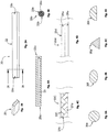
- a spinal fixation construct 1 in accordance with an embodiment of the present disclosure includes a fixation member 10, a flexible member 20, a spinal rod 30, and at least one bone screw 40. While two spinal fixation constructs 1 are shown in FIG. 1 , the spinal fixation constructs 1 are discussed singularly as they are substantially identical.
- the fixation member 10 includes a proximal end 12 including a head portion 14, and a threaded body portion 16 extending distally from the head portion 14 to a distal tip 18 along a longitudinal axis "X".
- the head portion 14 of the fixation member 10 defines a hole 14a therethrough that is configured and dimensioned to receive and retain a portion of the flexible member 20 (see e.g., FIG. 1 ).
- the hole 14a has a lateral dimension that is larger than a longitudinal dimension of the hole 14a.
- the threaded body portion 16 of the fixation member 10 includes a first threaded region 16a and a second threaded region 16b.
- the fixation member 10 is formed or machined from a biocompatible metallic material including, but not limited to, titanium alloy, stainless steel, and cobalt chrome.
- the flexible member 20 includes an elongated body 22 having a first end portion 22a and a second end portion 22b.
- the flexible member 20 is formed from a biocompatible material having a lower modulus of elasticity than the biocompatible material of the fixation member 10 (see e.g., FIG. 2 ) and thus, the flexible member 20 is formed of a less stiff material than that of the fixation member 10.
- the flexible member 20 may be fabricated from one or more polymeric materials such as, but not limited to, polyethylene, ultra-high molecular weight polyethylene, polypropylene, polyetherimide, polysulfone, polyacetal, nylon, polytetrafluoroethylene, and combinations thereof, and may be formed by injection molding, extruding, compression molding, overmolding, machining or other known methods for shaping polymeric materials as within the purview of those skilled in the art.
- polymeric materials such as, but not limited to, polyethylene, ultra-high molecular weight polyethylene, polypropylene, polyetherimide, polysulfone, polyacetal, nylon, polytetrafluoroethylene, and combinations thereof, and may be formed by injection molding, extruding, compression molding, overmolding, machining or other known methods for shaping polymeric materials as within the purview of those skilled in the art.
- the elongated body 22 of the flexible member 20 has a uniform dimension along the length thereof, and as shown in FIG. 3B , is a solid monolithic structure having a generally rectangular cross-sectional shape. It is envisioned that the dimensions of the elongated body 22 of the flexible member 20 may vary along the length thereof.
- the elongated body 22a of a flexible member 20a may have an opening 23 defined therethrough to increase the flexibility of the flexible member 20a.
- the flexible member may be a composite.
- an elongated body 22b of a flexible member 20b has a core 25a and sheath 25b configuration in which the core 25a and sheath 25b may be formed of the same or different materials having the same or different moduli of elasticities. As shown in FIG.
- an elongated body 22c of a flexible member 20c has a braided configuration in which first strand(s) 27a of the elongated body 22c are formed from the same or different material having the same or different modulus of elasticity than second strand(s) 27b of the elongated body 22c.
- an elongated body 22d of a flexible member 20d has a layered configuration including two or more layers 29a, 29b which may be formed from the same or different materials having the same or different modulus of elasticities.
- the flexible member may have other cross-sectional shapes, such as a flexible member 20e having a circular shape ( FIG.
- FIG. 5A a flexible member 20f having an elliptical shape
- FIG. 5B a flexible member 20g having a triangular shape
- FIG. 5C a flexible member 20h having a semi-circular shape
- FIG. 5D a semi-circular shape
- the combination of, for example, size, configuration, shape, and/or material selection of the elongated body of the flexible member provides the flexible member with a desired stiffness profile along the length thereof for a desired surgical application.
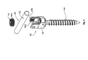
- the spinal rod 30 includes an elongated body 32 having opposed ends, and the bone screw 40 includes a housing 42, a bone screw member 44, and a set screw 46.
- Housing 42 of bone screw 40 includes a saddle portion 42a within which the spinal rod 30 may be seated.
- Housing 42 also includes internal threads 42b configured to engage complementary external threads 46a of the set screw 46 to secure the set screw 46 within the housing 42 and to secure the spinal rod 30 within the saddle portion 42a of the housing 42.
- Suitable spinal rods and bone screws for use in the spinal fixation construct of the present disclosure are shown and described in U.S. Patent Application Publication Nos. 2013/0013003 and 2013/0144342 , and U.S. Patent No. 8,882,817 .
- the spinal rod 30 and bone screw(s) 40 are formed from biocompatible metallic materials, such as those listed above with regard to the fixation member 10 and thus, the flexible member 20 is formed of a less stiff material than that of the spinal rod 30 and the bone screw(s) 40.
- the fixation member 10 is implanted within a bony element of a spine "S," such as the pedicle or facet.
- the bone screws 40 are implanted into vertebral bodies “V” of the spine "S” in spaced relation relative to the fixation member 10 and relative to each other, and the spinal rod 30 is positioned within the bone screws 40.
- the flexible member 20 is passed through the hole 14a (see e.g., FIG. 2 ) of the head portion 14 of the fixation member 10 such that a portion of the flexible member 20 is secured within the head portion 14 of the fixation member 10, and the first and second end portions 22a and 22b (see e.g., FIG.
- a spinal fixation construct 2 in accordance with another embodiment of the present disclosure includes a fixation member 110, a flexible member 20, a spinal rod 30, and at least one bone screw 40.
- the fixation member 110 includes a proximal end 112 including a head portion 114 and a threaded body portion 116 extending distally from the head portion 114 to a distal tip 118 along a longitudinal axis "X".
- the head portion 114 of the fixation member 110 defines a hole 114a therethrough that is configured and dimensioned to receive a portion of the flexible member 20 (see e.g., FIG. 7 ).
- the hole 114a has a lateral dimension that is smaller than a longitudinal dimension of the hole 114a.
- the threaded body portion 116 of the fixation member 110 includes a first threaded region 116a and a second threaded region 116b.
- the fixation member 110 is implanted within a bony structure of a spine "S," such as the pedicle or facet.
- the bone screws 40 are implanted into vertebral bodies “V” of the spine "S” in spaced relation relative to the fixation member 110 and relative to each other, and the spinal rod 30 is positioned within the bone screws 40.
- the flexible member 20 is passed through the hole 114a (see e.g., FIG. 8 ) of the head portion 114 of the fixation member 110 such that a portion of the flexible member 20 is secured within the head portion 114 of the fixation member 110, and the first and second end portions 22a and 22b (see e.g., FIG. 3A ) of the flexible member 20 are placed adjacent to the spinal rod 30 within the saddle portion 42a (see e.g., FIG. 6 ) of the housing 42 of the bone screw 40, and secured therein by the set screw 46.
- a spinal fixation construct 3 in accordance with another embodiment of the present disclosure includes a fixation member 110, flexible member 20, a spinal rod 300, and at least one bone screw 40.
- the spinal rod 300 includes an elongated body 302 having a first end 304 and a second end 306.
- the first end 304 defines an aperture or through hole 304a therethrough which is configured and dimensioned to engage a portion of the flexible member 20 (see e.g., FIG. 9 ).
- a spinal rod 300' includes an elongated body 302' having a first end 304 defining an aperture 304a therethrough, and a second end 306' defining an aperture 306a therethrough for use with a flexible member.
- the fixation member 110 is implanted within a bony element of a spine "S," the bone screw 40 is implanted into a vertebral body "V" of the spine “S” in spaced relation relative to the fixation member 110, and the spinal rod 300 is positioned within the bone screw 40.
- the flexible member 20 is passed through the hole 114a (see e.g., FIG. 8 ) of the fixation member 110 and the aperture 304a of the spinal rod 300 such that portions of the flexible member 20 are secured within the head portion 114 of the fixation member 110 and the first end 304 of the spinal rod 300.
- the first and second end portions 22a and 22b (see e.g., FIG. 3A ) of the flexible member 20 are secured, e.g., by being tied or clamped, to the fixation member 110, the spinal rod 300, and/or to each other, such that the flexible member 20 forms a continuous loop.
- a spinal fixation construct 4 in accordance with another embodiment of the present disclosure includes two fixation members 110, a flexible member 20, two spinal rods 300, and a plurality of bone screws 40.
- the fixation members 110 are implanted within a bony element of a spine "S" on opposed sides of the spinous process "SP.”
- the bone screws 40 are implanted into vertebral bodies "V” of the spine "S” in spaced relation relative to the fixation members 110, also on opposed sides of the spinous process "SP,” and the spinal rods 300 are positioned within the bone screws 40.
- the flexible member 20 is passed through the holes 114a (see e.g., FIG.
- the first and second end portions 22a, 22b ( FIG. 3A ) of the flexible member 20 are secured, e.g., by being tied or clamped, to the fixation member 110, the spinal rod 300, and/or to each other.
- the spinal fixation constructs 1-4 have been shown with the flexible member 20 oriented in a cranial orientation to facilitate reducing the stress impact on the cranial, non-instrumented adjacent level to the spinal fixation construct 1-4, it should be understood that if a less stiff portion is desired at the caudal end of the spinal fixation construct 1-4, the spinal fixation construct 1-4 may be turned 180 degrees to allow the flexible member 20 to be located in a caudal orientation and/or the spinal fixation construct 1-4 may be stopped one level above the desired level. Should both the cranial and caudal ends require less stiffness, both ends may include the flexible member 20.
- the modulus of elasticity of the flexible member 20 is different from the modulus of elasticity of the other components of the spinal fixation construct 1-4 (e.g., the spinal rod 30, 300, 300'), and thus, a range of motion is maintained between adjacent vertebrae without spinal fusion.
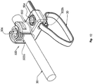
- the flexible member may be configured to loop around a portion of a bony element, such as a vertebral body, and coupled to a spinal rod with a spinal implant, such as an implant depicted in U.S. Patent Application No. 2014/0257397 .
- the spinal implant 500 includes an implant housing 502 that defines a rod passage 502a and an implant passage 502b.
- the rod passage 502a is configured to receive a portion of a spinal rod 30 and the implant passage 502b is configured to receive a portion of the flexible member 20.
- An implant set screw 504 engages the flexible member 20 when the flexible member 20 is received within the implant passage 502b to fix the flexible member 20 relative to the implant housing 502, and a rod set screw 506 engages the spinal rod 30 disposed within the rod passage 502a to fix the spinal rod 30 relative to the implant housing 502.
- a surgical instrument such as that described in commonly owned U.S. Patent Application No. 14/644,428 may be used by a clinician to tension the flexible member 20 about the bony element and/or fix the flexible member 20 to the spinal implant 500.
- the spinal fixation construct may be provided in a kit.
- the kit is an assembled package with at least one flexible member, at least one fixation member, at least one spinal rod, and/or bone screw(s).
- the kit may include any and/or all of the configurations of: the flexible member 20, 20a-20h; the fixation members 10, 110; the spinal rods 30, 300, 300'; and/or the bone screws 40, described above.
- the kit may include a plurality of flexible members, fixation members, spinal rods, and/or bone screws having, for example, different configurations, diameters, lengths, and/or shapes. Accordingly, a clinician may pick and choose components to form a spinal fixation construct with a desired stiffness profile for a surgical procedure.
- a clinician may perform any required anterior procedures and then turn the patient to a prone position.
- the clinician can create a spinal fixation construct which may be a combination of any of the components described above, and include additional components, such as bone anchors, transverse connectors, etc.
- the clinician implants any fixation members, bone screws, and/or bone anchors, and spinal rods posteriorly, and then supplements the posterior instrumentation with the flexible member.
- the flexible member may be looped over the lamina, through the spinous process, over the spinous process, or anchored to a fixation member and/or a spinal rod, as desired by the clinician for the particular surgical procedure.
- the first and second end portions of the flexible member may be placed in the saddle portion of a bone screw adjacent the spinal rod and locked in place by the set screw of the bone screw, one or both end portions may be tied through a through hole of a fixation member and/or a spinal rod, as desired by the clinician for the particular surgical procedure.
- the flexible member may be placed at the cranial and/or caudal end of the spinal fixation construct.
Landscapes
- Health & Medical Sciences (AREA)
- Orthopedic Medicine & Surgery (AREA)
- Life Sciences & Earth Sciences (AREA)
- Surgery (AREA)
- Neurology (AREA)
- Heart & Thoracic Surgery (AREA)
- Engineering & Computer Science (AREA)
- Biomedical Technology (AREA)
- Nuclear Medicine, Radiotherapy & Molecular Imaging (AREA)
- Medical Informatics (AREA)
- Molecular Biology (AREA)
- Animal Behavior & Ethology (AREA)
- General Health & Medical Sciences (AREA)
- Public Health (AREA)
- Veterinary Medicine (AREA)
- Surgical Instruments (AREA)
- Prostheses (AREA)
Claims (10)
- Wirbelsäulenfixierungskonstrukt zum Ausrichten von Wirbelkörpern, umfassend:eine Knochenschraube (40), beinhaltend ein Gehäuse (42) mit einem Sattelabschnitt (42a), und ein Knochenschraubenelement (44), das sich von dem Gehäuse erstreckt;einen Wirbelsäulenstab (30), der innerhalb des Sattelabschnitts des Gehäuses der Knochenschraube angeordnet ist, wobei der Wirbelsäulenstab einen länglichen Körper (32) mit einem ersten Ende und einem zweiten Ende beinhaltet, wobei der Wirbelsäulenstab aus einem ersten Material mit einem ersten Elastizitätsmodul hergestellt ist;ein flexibles Element (20), beinhaltend einen länglichen Körper (22) mit einem ersten Endabschnitt (22a) und einem zweiten Endabschnitt (22b), wobei das flexible Element aus einem zweiten Material mit einem zweiten Elastizitätsmodul, der sich von dem ersten Elastizitätsmodul unterscheidet, hergestellt ist; undein Fixierungselement (10), beinhaltend einen Gewindekörperabschnitt (16) und einen Kopfabschnitt (14), der eine Öffnung (14a) dort hindurch definiert, dadurch gekennzeichnet, dassein erster Abschnitt des flexiblen Elements sich durch die Öffnung des Kopfabschnitts erstreckt und der erste und der zweite Endabschnitt des flexiblen Elements an den Wirbelsäulenstab gekoppelt sind, so dass das Wirbelsäulenfixierungskonstrukt eine variierende Steifigkeit entlang seiner Länge aufweist.
- Wirbelsäulenfixierungskonstrukt nach Anspruch 1, wobei das Fixierungselement (10) aus einem dritten Material mit einem dritten Elastizitätsmodul, der sich von dem ersten Elastizitätsmodul unterscheidet, hergestellt ist.
- Wirbelsäulenfixierungskonstrukt nach einem der vorhergehenden Ansprüche, wobei die Öffnung (14a) des Fixierungselements eine Seitenabmessung aufweist, die sich von einer Längsabmessung der Öffnung unterscheidet.
- Wirbelsäulenfixierungskonstrukt nach einem der vorhergehenden Ansprüche, wobei der längliche Körper des flexiblen Elements umflochten ist.
- Wirbelsäulenfixierungskonstrukt nach einem der vorhergehenden Ansprüche, wobei die Knochenschraube eine Stellschraube (46) mit Außengewinden beinhaltet, die dazu konfiguriert sind, Innengewinde des Gehäuses in Eingriff zu nehmen, und wobei der erste und der zweite Endabschnitt des flexiblen Elements gegen den Wirbelsäulenstab innerhalb des Sattelabschnitts des Gehäuses komprimierbar und darin durch die Stellschraube sicherbar sind.
- Wirbelsäulenfixierungskonstrukt nach einem der Ansprüche 1-4, wobei das erste Ende (304) des Wirbelsäulenstabs einen Durchbruch (304a) dort hindurch definiert und ein zweiter Abschnitt des flexiblen Elements sich durch den Durchbruch erstreckt.
- Wirbelsäulenfixierungskonstrukt nach Anspruch 6, wobei das zweite Ende (306) des Wirbelsäulenstabs einen Durchbruch (306a) dort hindurch definiert.
- Wirbelsäulenfixierungskonstrukt nach einem der vorhergehenden Ansprüche, wobei der erste Elastizitätsmodul höher als der zweite Elastizitätsmodul ist.
- Wirbelsäulenfixierungskonstrukt nach Anspruch 2, wobei der erste Elastizitätsmodul und der dritte Elastizitätsmodul höher als der zweite Elastizitätsmodul sind.
- Wirbelsäulenfixierungskonstrukt nach einem der vorhergehenden Ansprüche, wobei das flexible Element an das erste Ende des Wirbelsäulenstabs gekoppelt ist.
Applications Claiming Priority (2)
| Application Number | Priority Date | Filing Date | Title |
|---|---|---|---|
| US201562115259P | 2015-02-12 | 2015-02-12 | |
| EP16155445.6 | 2016-02-12 |
Related Parent Applications (1)
| Application Number | Title | Priority Date | Filing Date |
|---|---|---|---|
| EP16155445.6 Division | 2015-02-12 | 2016-02-12 |
Publications (2)
| Publication Number | Publication Date |
|---|---|
| EP3095400A1 EP3095400A1 (de) | 2016-11-23 |
| EP3095400B1 true EP3095400B1 (de) | 2021-12-15 |
Family
ID=55353111
Family Applications (1)
| Application Number | Title | Priority Date | Filing Date |
|---|---|---|---|
| EP16173488.4A Active EP3095400B1 (de) | 2015-02-12 | 2016-02-12 | Wirbelsäulenfixierungskonstrukt |
Country Status (3)
| Country | Link |
|---|---|
| US (4) | US10064656B2 (de) |
| EP (1) | EP3095400B1 (de) |
| AU (1) | AU2016200919B2 (de) |
Families Citing this family (16)
| Publication number | Priority date | Publication date | Assignee | Title |
|---|---|---|---|---|
| US9675386B2 (en) | 2013-03-11 | 2017-06-13 | K2M, Inc. | Flexible fastening system |
| US11213325B2 (en) * | 2013-03-15 | 2022-01-04 | Jcbd, Llc | Spinal stabilization system with adjustable interlaminar devices |
| FR3010628B1 (fr) | 2013-09-18 | 2015-10-16 | Medicrea International | Procede permettant de realiser la courbure ideale d'une tige d'un materiel d'osteosynthese vertebrale destinee a etayer la colonne vertebrale d'un patient |
| FR3012030B1 (fr) | 2013-10-18 | 2015-12-25 | Medicrea International | Procede permettant de realiser la courbure ideale d'une tige d'un materiel d'osteosynthese vertebrale destinee a etayer la colonne vertebrale d'un patient |
| EP3285667B1 (de) * | 2015-04-24 | 2022-12-14 | K2M, Inc. | Fixierschraubensystem |
| DE102016011947A1 (de) * | 2016-10-05 | 2018-04-05 | Bluewater Medical GmbH | Schraube mit einem Kopfteil, einem Gewindeteil und einem Verbindungsteil |
| US10463403B2 (en) | 2017-07-31 | 2019-11-05 | Medos International Sarl | Systems and methods for reducing the risk of proximal junctional kyphosis using a bone anchor or other attachment point |
| US10456174B2 (en) * | 2017-07-31 | 2019-10-29 | Medos International Sarl | Connectors for use in systems and methods for reducing the risk of proximal junctional kyphosis |
| US10918422B2 (en) * | 2017-12-01 | 2021-02-16 | Medicrea International | Method and apparatus for inhibiting proximal junctional failure |
| US11344337B2 (en) * | 2018-02-19 | 2022-05-31 | Zimmer Biomet Spine, Inc. | Systems for attenuation of increased spinal flexion loads post-fusion and associated methods |
| US11020149B2 (en) * | 2018-02-28 | 2021-06-01 | Globus Medical Inc. | Scoliosis correction systems, methods, and instruments |
| US11771472B2 (en) * | 2019-10-29 | 2023-10-03 | Globus Medical, Inc. | Sublaminar band clamp |
| US11974785B2 (en) | 2020-10-16 | 2024-05-07 | Globus Medical, Inc | Band clamp implants |
| US11771475B2 (en) | 2020-10-07 | 2023-10-03 | Globus Medical, Inc. | Systems and methods for surgical procedures using band clamp implants and tensioning instruments |
| EP4166103A1 (de) * | 2021-10-12 | 2023-04-19 | Chien-Yu Chen | Translaminares pedikelanker-aufhängungssystem und pedikelanker dafür |
| US11877775B1 (en) * | 2022-11-21 | 2024-01-23 | Warsaw Orthopedic, Inc. | Multiaxial receivers with tether |
Family Cites Families (48)
| Publication number | Priority date | Publication date | Assignee | Title |
|---|---|---|---|---|
| DE59305375D1 (de) | 1992-08-12 | 1997-03-20 | Synthes Ag | Wirbelsäulenfixationselement |
| US5312410A (en) | 1992-12-07 | 1994-05-17 | Danek Medical, Inc. | Surgical cable tensioner |
| US5496318A (en) | 1993-01-08 | 1996-03-05 | Advanced Spine Fixation Systems, Inc. | Interspinous segmental spine fixation device |
| US5449361A (en) | 1993-04-21 | 1995-09-12 | Amei Technologies Inc. | Orthopedic cable tensioner |
| US5417690A (en) | 1993-09-20 | 1995-05-23 | Codman & Shurtleff, Inc. | Surgical cable |
| US6086590A (en) | 1999-02-02 | 2000-07-11 | Pioneer Laboratories, Inc. | Cable connector for orthopaedic rod |
| JP2001314416A (ja) * | 2000-05-10 | 2001-11-13 | Showa Ika Kohgyo Co Ltd | 骨接合具用のロッド |
| AU2002239723B2 (en) | 2000-10-24 | 2004-08-26 | The Spineology Group, Llc | Tension band clip |
| FR2858929B1 (fr) | 2003-08-21 | 2005-09-30 | Spine Next Sa | "implant intervertebral pour l'articulation lombo-sacree" |
| US7083622B2 (en) * | 2003-11-10 | 2006-08-01 | Simonson Peter M | Artificial facet joint and method |
| US7458981B2 (en) | 2004-03-09 | 2008-12-02 | The Board Of Trustees Of The Leland Stanford Junior University | Spinal implant and method for restricting spinal flexion |
| US8454657B2 (en) * | 2004-06-15 | 2013-06-04 | Warsaw Orthopedic, Inc. | Medical systems for the spine and related methods |
| US20070088359A1 (en) * | 2005-02-07 | 2007-04-19 | Woods Richard W | Universal dynamic spine stabilization device and method of use |
| US20060229607A1 (en) * | 2005-03-16 | 2006-10-12 | Sdgi Holdings, Inc. | Systems, kits and methods for treatment of the spinal column using elongate support members |
| US8273086B2 (en) * | 2005-03-24 | 2012-09-25 | Depuy Spine, Inc. | Low profile spinal tethering devices |
| FR2890851B1 (fr) | 2005-09-21 | 2008-06-20 | Abbott Spine Sa | Ancillaire de mise en tension d'un lien souple. |
| ES2729413T3 (es) * | 2005-11-24 | 2019-11-04 | Giuseppe Calvosa | Estabilizador modular de vértebras |
| KR100829338B1 (ko) * | 2006-12-07 | 2008-05-13 | 김수경 | 척추 고정 장치 |
| US8057516B2 (en) * | 2007-03-21 | 2011-11-15 | Zimmer Spine, Inc. | Spinal stabilization system with rigid and flexible elements |
| US20080269805A1 (en) * | 2007-04-25 | 2008-10-30 | Warsaw Orthopedic, Inc. | Methods for correcting spinal deformities |
| EP2052689B1 (de) | 2007-10-23 | 2011-12-14 | Zimmer Spine | Befestigungsvorrichtungen und Stabilisierungssysteme mit diesen Befestigungsvorrichtungen |
| US20090204118A1 (en) | 2008-02-13 | 2009-08-13 | William Ralph Pratt | Surgical cable with malleable leader segment |
| EP2138122A1 (de) * | 2008-06-25 | 2009-12-30 | Abbott Spine | Stabilisationssystem zwischen dem Kreuzbein und einem Lendenwirbel |
| EP2184023B1 (de) | 2008-11-07 | 2016-06-29 | Zimmer Spine | Operationsinstrument zur Spannung eines flexiblen Elements |
| US20100160968A1 (en) * | 2008-12-19 | 2010-06-24 | Abbott Spine Inc. | Systems and methods for pedicle screw-based spine stabilization using flexible bands |
| US20110009906A1 (en) * | 2009-07-13 | 2011-01-13 | Zimmer Spine, Inc. | Vertebral stabilization transition connector |
| US20110066187A1 (en) * | 2009-09-11 | 2011-03-17 | Zimmer Spine, Inc. | Spinal stabilization system |
| US8236032B2 (en) | 2009-10-20 | 2012-08-07 | Depuy Spine, Inc. | Spinal implant with a flexible extension element |
| EP2316363A1 (de) | 2009-10-27 | 2011-05-04 | Zimmer Spine | Knochenhaltevorrichtung |
| US8216245B2 (en) | 2009-10-30 | 2012-07-10 | Warsaw Orthopedic | Apparatus and method for applying sustained tension on a tether |
| US9393048B2 (en) | 2010-02-23 | 2016-07-19 | K2M, Inc. | Polyaxial bonescrew assembly |
| US20110301644A1 (en) | 2010-06-08 | 2011-12-08 | Zimmer Spine | Spinal stabilization system |
| US9295494B2 (en) | 2010-06-28 | 2016-03-29 | K2M, Inc. | Spine stabilization system |
| EP2605716B1 (de) | 2010-08-20 | 2021-04-21 | K2M, Inc. | Wirbelsäulenfixierungssystem |
| FR2976783B1 (fr) | 2011-06-22 | 2014-05-09 | Medicrea International | Materiel d'osteosynthese vertebrale |
| FR2977138B1 (fr) | 2011-06-30 | 2014-02-28 | Implanet | Dispositif de fixation vertebrale |
| US8636770B2 (en) | 2011-08-08 | 2014-01-28 | Zimmer Spine, Inc. | Bone anchoring device |
| WO2013040456A1 (en) * | 2011-09-14 | 2013-03-21 | Band-Lok, Llc | Tether clamp and implantation system |
| US20130253587A1 (en) * | 2012-03-20 | 2013-09-26 | Warsaw Orthopedic, Inc. | Spinal systems and methods for correction of spinal disorders |
| US20140025116A1 (en) * | 2012-07-23 | 2014-01-23 | Chih-Hsuan Wei | Fixing Structure of Bone Screws and a Connecting Rod for a Minimally Invasive Surgery |
| US9757160B2 (en) * | 2012-09-28 | 2017-09-12 | Globus Medical, Inc. | Device and method for treatment of spinal deformity |
| US9433441B2 (en) | 2013-03-05 | 2016-09-06 | Globus Medical, Inc. | Elastic member clamps |
| US10034692B2 (en) | 2013-03-05 | 2018-07-31 | Globus Medical, Inc. | Elastic member clamps |
| US10548644B2 (en) | 2013-03-05 | 2020-02-04 | Globus Medical, Inc. | Elastic member clamps |
| US9675386B2 (en) | 2013-03-11 | 2017-06-13 | K2M, Inc. | Flexible fastening system |
| US9820784B2 (en) | 2013-03-14 | 2017-11-21 | Spinal Elements, Inc. | Apparatus for spinal fixation and methods of use |
| US9421044B2 (en) * | 2013-03-14 | 2016-08-23 | Spinal Elements, Inc. | Apparatus for bone stabilization and distraction and methods of use |
| US9757167B2 (en) | 2015-03-11 | 2017-09-12 | K2M, Inc. | Inserter and method for securing an implant to a spinal process with a flexible fastening system |
-
2016
- 2016-02-12 EP EP16173488.4A patent/EP3095400B1/de active Active
- 2016-02-12 AU AU2016200919A patent/AU2016200919B2/en not_active Ceased
- 2016-02-12 US US15/042,184 patent/US10064656B2/en active Active
-
2018
- 2018-08-22 US US16/108,126 patent/US10582953B2/en active Active
-
2020
- 2020-02-19 US US16/794,546 patent/US11672567B2/en active Active
-
2023
- 2023-05-03 US US18/142,805 patent/US20230293206A1/en active Pending
Also Published As
| Publication number | Publication date |
|---|---|
| US20200179013A1 (en) | 2020-06-11 |
| EP3095400A1 (de) | 2016-11-23 |
| US10582953B2 (en) | 2020-03-10 |
| US20160235447A1 (en) | 2016-08-18 |
| US11672567B2 (en) | 2023-06-13 |
| AU2016200919A1 (en) | 2016-09-01 |
| US20230293206A1 (en) | 2023-09-21 |
| US10064656B2 (en) | 2018-09-04 |
| US20180353216A1 (en) | 2018-12-13 |
| AU2016200919B2 (en) | 2020-08-27 |
Similar Documents
| Publication | Publication Date | Title |
|---|---|---|
| US11672567B2 (en) | Spinal fixation construct and methods of use | |
| US11051860B2 (en) | Spinal construct with flexible member | |
| US8882817B2 (en) | Spinal fixation system | |
| US7708762B2 (en) | Systems, devices and methods for stabilization of the spinal column | |
| US8523922B2 (en) | Dynamic multi-axial fastener | |
| US20240197366A1 (en) | Spinal fixation constructs and related methods | |
| US20120065687A1 (en) | Multi-Radius Vertebral Rod With a Varying Stiffness | |
| US9795413B2 (en) | Spinal fixation member | |
| US11457960B2 (en) | Lateral spine stabilization devices and methods | |
| US20130218207A1 (en) | Dynamic multi-axial anchor | |
| US9095378B2 (en) | Spinal stabilization system | |
| US10631899B2 (en) | Flexible spine stabilization system | |
| US20120245693A1 (en) | Spinal fixation device | |
| US20210228241A1 (en) | Polyaxial Lateral Offset Connector |
Legal Events
| Date | Code | Title | Description |
|---|---|---|---|
| PUAI | Public reference made under article 153(3) epc to a published international application that has entered the european phase |
Free format text: ORIGINAL CODE: 0009012 |
|
| AK | Designated contracting states |
Kind code of ref document: A1 Designated state(s): AL AT BE BG CH CY CZ DE DK EE ES FI FR GB GR HR HU IE IS IT LI LT LU LV MC MK MT NL NO PL PT RO RS SE SI SK SM TR |
|
| AX | Request for extension of the european patent |
Extension state: BA ME |
|
| STAA | Information on the status of an ep patent application or granted ep patent |
Free format text: STATUS: REQUEST FOR EXAMINATION WAS MADE |
|
| 17P | Request for examination filed |
Effective date: 20170516 |
|
| RBV | Designated contracting states (corrected) |
Designated state(s): AL AT BE BG CH CY CZ DE DK EE ES FI FR GB GR HR HU IE IS IT LI LT LU LV MC MK MT NL NO PL PT RO RS SE SI SK SM TR |
|
| RAP1 | Party data changed (applicant data changed or rights of an application transferred) |
Owner name: K2M, INC. |
|
| GRAP | Despatch of communication of intention to grant a patent |
Free format text: ORIGINAL CODE: EPIDOSNIGR1 |
|
| STAA | Information on the status of an ep patent application or granted ep patent |
Free format text: STATUS: GRANT OF PATENT IS INTENDED |
|
| INTG | Intention to grant announced |
Effective date: 20210723 |
|
| GRAS | Grant fee paid |
Free format text: ORIGINAL CODE: EPIDOSNIGR3 |
|
| GRAA | (expected) grant |
Free format text: ORIGINAL CODE: 0009210 |
|
| STAA | Information on the status of an ep patent application or granted ep patent |
Free format text: STATUS: THE PATENT HAS BEEN GRANTED |
|
| AK | Designated contracting states |
Kind code of ref document: B1 Designated state(s): AL AT BE BG CH CY CZ DE DK EE ES FI FR GB GR HR HU IE IS IT LI LT LU LV MC MK MT NL NO PL PT RO RS SE SI SK SM TR |
|
| REG | Reference to a national code |
Ref country code: GB Ref legal event code: FG4D Ref country code: CH Ref legal event code: EP |
|
| REG | Reference to a national code |
Ref country code: IE Ref legal event code: FG4D Ref country code: DE Ref legal event code: R096 Ref document number: 602016067313 Country of ref document: DE |
|
| REG | Reference to a national code |
Ref country code: AT Ref legal event code: REF Ref document number: 1454889 Country of ref document: AT Kind code of ref document: T Effective date: 20220115 |
|
| REG | Reference to a national code |
Ref country code: LT Ref legal event code: MG9D |
|
| REG | Reference to a national code |
Ref country code: NL Ref legal event code: MP Effective date: 20211215 |
|
| PG25 | Lapsed in a contracting state [announced via postgrant information from national office to epo] |
Ref country code: RS Free format text: LAPSE BECAUSE OF FAILURE TO SUBMIT A TRANSLATION OF THE DESCRIPTION OR TO PAY THE FEE WITHIN THE PRESCRIBED TIME-LIMIT Effective date: 20211215 Ref country code: LT Free format text: LAPSE BECAUSE OF FAILURE TO SUBMIT A TRANSLATION OF THE DESCRIPTION OR TO PAY THE FEE WITHIN THE PRESCRIBED TIME-LIMIT Effective date: 20211215 Ref country code: FI Free format text: LAPSE BECAUSE OF FAILURE TO SUBMIT A TRANSLATION OF THE DESCRIPTION OR TO PAY THE FEE WITHIN THE PRESCRIBED TIME-LIMIT Effective date: 20211215 Ref country code: BG Free format text: LAPSE BECAUSE OF FAILURE TO SUBMIT A TRANSLATION OF THE DESCRIPTION OR TO PAY THE FEE WITHIN THE PRESCRIBED TIME-LIMIT Effective date: 20220315 |
|
| REG | Reference to a national code |
Ref country code: AT Ref legal event code: MK05 Ref document number: 1454889 Country of ref document: AT Kind code of ref document: T Effective date: 20211215 |
|
| PG25 | Lapsed in a contracting state [announced via postgrant information from national office to epo] |
Ref country code: SE Free format text: LAPSE BECAUSE OF FAILURE TO SUBMIT A TRANSLATION OF THE DESCRIPTION OR TO PAY THE FEE WITHIN THE PRESCRIBED TIME-LIMIT Effective date: 20211215 Ref country code: NO Free format text: LAPSE BECAUSE OF FAILURE TO SUBMIT A TRANSLATION OF THE DESCRIPTION OR TO PAY THE FEE WITHIN THE PRESCRIBED TIME-LIMIT Effective date: 20220315 Ref country code: LV Free format text: LAPSE BECAUSE OF FAILURE TO SUBMIT A TRANSLATION OF THE DESCRIPTION OR TO PAY THE FEE WITHIN THE PRESCRIBED TIME-LIMIT Effective date: 20211215 Ref country code: HR Free format text: LAPSE BECAUSE OF FAILURE TO SUBMIT A TRANSLATION OF THE DESCRIPTION OR TO PAY THE FEE WITHIN THE PRESCRIBED TIME-LIMIT Effective date: 20211215 Ref country code: GR Free format text: LAPSE BECAUSE OF FAILURE TO SUBMIT A TRANSLATION OF THE DESCRIPTION OR TO PAY THE FEE WITHIN THE PRESCRIBED TIME-LIMIT Effective date: 20220316 |
|
| PG25 | Lapsed in a contracting state [announced via postgrant information from national office to epo] |
Ref country code: NL Free format text: LAPSE BECAUSE OF FAILURE TO SUBMIT A TRANSLATION OF THE DESCRIPTION OR TO PAY THE FEE WITHIN THE PRESCRIBED TIME-LIMIT Effective date: 20211215 |
|
| PG25 | Lapsed in a contracting state [announced via postgrant information from national office to epo] |
Ref country code: SM Free format text: LAPSE BECAUSE OF FAILURE TO SUBMIT A TRANSLATION OF THE DESCRIPTION OR TO PAY THE FEE WITHIN THE PRESCRIBED TIME-LIMIT Effective date: 20211215 Ref country code: SK Free format text: LAPSE BECAUSE OF FAILURE TO SUBMIT A TRANSLATION OF THE DESCRIPTION OR TO PAY THE FEE WITHIN THE PRESCRIBED TIME-LIMIT Effective date: 20211215 Ref country code: PT Free format text: LAPSE BECAUSE OF FAILURE TO SUBMIT A TRANSLATION OF THE DESCRIPTION OR TO PAY THE FEE WITHIN THE PRESCRIBED TIME-LIMIT Effective date: 20220418 Ref country code: ES Free format text: LAPSE BECAUSE OF FAILURE TO SUBMIT A TRANSLATION OF THE DESCRIPTION OR TO PAY THE FEE WITHIN THE PRESCRIBED TIME-LIMIT Effective date: 20211215 Ref country code: EE Free format text: LAPSE BECAUSE OF FAILURE TO SUBMIT A TRANSLATION OF THE DESCRIPTION OR TO PAY THE FEE WITHIN THE PRESCRIBED TIME-LIMIT Effective date: 20211215 Ref country code: CZ Free format text: LAPSE BECAUSE OF FAILURE TO SUBMIT A TRANSLATION OF THE DESCRIPTION OR TO PAY THE FEE WITHIN THE PRESCRIBED TIME-LIMIT Effective date: 20211215 |
|
| PG25 | Lapsed in a contracting state [announced via postgrant information from national office to epo] |
Ref country code: PL Free format text: LAPSE BECAUSE OF FAILURE TO SUBMIT A TRANSLATION OF THE DESCRIPTION OR TO PAY THE FEE WITHIN THE PRESCRIBED TIME-LIMIT Effective date: 20211215 Ref country code: AT Free format text: LAPSE BECAUSE OF FAILURE TO SUBMIT A TRANSLATION OF THE DESCRIPTION OR TO PAY THE FEE WITHIN THE PRESCRIBED TIME-LIMIT Effective date: 20211215 |
|
| REG | Reference to a national code |
Ref country code: DE Ref legal event code: R097 Ref document number: 602016067313 Country of ref document: DE |
|
| PG25 | Lapsed in a contracting state [announced via postgrant information from national office to epo] |
Ref country code: MC Free format text: LAPSE BECAUSE OF FAILURE TO SUBMIT A TRANSLATION OF THE DESCRIPTION OR TO PAY THE FEE WITHIN THE PRESCRIBED TIME-LIMIT Effective date: 20211215 Ref country code: IS Free format text: LAPSE BECAUSE OF FAILURE TO SUBMIT A TRANSLATION OF THE DESCRIPTION OR TO PAY THE FEE WITHIN THE PRESCRIBED TIME-LIMIT Effective date: 20220415 |
|
| REG | Reference to a national code |
Ref country code: CH Ref legal event code: PL |
|
| PLBE | No opposition filed within time limit |
Free format text: ORIGINAL CODE: 0009261 |
|
| STAA | Information on the status of an ep patent application or granted ep patent |
Free format text: STATUS: NO OPPOSITION FILED WITHIN TIME LIMIT |
|
| REG | Reference to a national code |
Ref country code: BE Ref legal event code: MM Effective date: 20220228 |
|
| PG25 | Lapsed in a contracting state [announced via postgrant information from national office to epo] |
Ref country code: LU Free format text: LAPSE BECAUSE OF NON-PAYMENT OF DUE FEES Effective date: 20220212 Ref country code: DK Free format text: LAPSE BECAUSE OF FAILURE TO SUBMIT A TRANSLATION OF THE DESCRIPTION OR TO PAY THE FEE WITHIN THE PRESCRIBED TIME-LIMIT Effective date: 20211215 Ref country code: AL Free format text: LAPSE BECAUSE OF FAILURE TO SUBMIT A TRANSLATION OF THE DESCRIPTION OR TO PAY THE FEE WITHIN THE PRESCRIBED TIME-LIMIT Effective date: 20211215 |
|
| 26N | No opposition filed |
Effective date: 20220916 |
|
| PG25 | Lapsed in a contracting state [announced via postgrant information from national office to epo] |
Ref country code: SI Free format text: LAPSE BECAUSE OF FAILURE TO SUBMIT A TRANSLATION OF THE DESCRIPTION OR TO PAY THE FEE WITHIN THE PRESCRIBED TIME-LIMIT Effective date: 20211215 |
|
| PG25 | Lapsed in a contracting state [announced via postgrant information from national office to epo] |
Ref country code: LI Free format text: LAPSE BECAUSE OF NON-PAYMENT OF DUE FEES Effective date: 20220228 Ref country code: CH Free format text: LAPSE BECAUSE OF NON-PAYMENT OF DUE FEES Effective date: 20220228 Ref country code: IE Free format text: LAPSE BECAUSE OF NON-PAYMENT OF DUE FEES Effective date: 20220212 |
|
| PGFP | Annual fee paid to national office [announced via postgrant information from national office to epo] |
Ref country code: GB Payment date: 20221222 Year of fee payment: 8 Ref country code: FR Payment date: 20221208 Year of fee payment: 8 |
|
| PG25 | Lapsed in a contracting state [announced via postgrant information from national office to epo] |
Ref country code: BE Free format text: LAPSE BECAUSE OF NON-PAYMENT OF DUE FEES Effective date: 20220228 |
|
| PG25 | Lapsed in a contracting state [announced via postgrant information from national office to epo] |
Ref country code: IT Free format text: LAPSE BECAUSE OF FAILURE TO SUBMIT A TRANSLATION OF THE DESCRIPTION OR TO PAY THE FEE WITHIN THE PRESCRIBED TIME-LIMIT Effective date: 20211215 |
|
| PGFP | Annual fee paid to national office [announced via postgrant information from national office to epo] |
Ref country code: DE Payment date: 20221220 Year of fee payment: 8 |
|
| P01 | Opt-out of the competence of the unified patent court (upc) registered |
Effective date: 20230522 |
|
| PG25 | Lapsed in a contracting state [announced via postgrant information from national office to epo] |
Ref country code: HU Free format text: LAPSE BECAUSE OF FAILURE TO SUBMIT A TRANSLATION OF THE DESCRIPTION OR TO PAY THE FEE WITHIN THE PRESCRIBED TIME-LIMIT; INVALID AB INITIO Effective date: 20160212 |
|
| PG25 | Lapsed in a contracting state [announced via postgrant information from national office to epo] |
Ref country code: RO Free format text: LAPSE BECAUSE OF FAILURE TO SUBMIT A TRANSLATION OF THE DESCRIPTION OR TO PAY THE FEE WITHIN THE PRESCRIBED TIME-LIMIT Effective date: 20211215 Ref country code: MK Free format text: LAPSE BECAUSE OF FAILURE TO SUBMIT A TRANSLATION OF THE DESCRIPTION OR TO PAY THE FEE WITHIN THE PRESCRIBED TIME-LIMIT Effective date: 20211215 Ref country code: CY Free format text: LAPSE BECAUSE OF FAILURE TO SUBMIT A TRANSLATION OF THE DESCRIPTION OR TO PAY THE FEE WITHIN THE PRESCRIBED TIME-LIMIT Effective date: 20211215 |
|
| PG25 | Lapsed in a contracting state [announced via postgrant information from national office to epo] |
Ref country code: TR Free format text: LAPSE BECAUSE OF FAILURE TO SUBMIT A TRANSLATION OF THE DESCRIPTION OR TO PAY THE FEE WITHIN THE PRESCRIBED TIME-LIMIT Effective date: 20211215 |