EP3094899B1 - Ventilblock mit hochstromflüssigkeit - Google Patents
Ventilblock mit hochstromflüssigkeit Download PDFInfo
- Publication number
- EP3094899B1 EP3094899B1 EP14869509.1A EP14869509A EP3094899B1 EP 3094899 B1 EP3094899 B1 EP 3094899B1 EP 14869509 A EP14869509 A EP 14869509A EP 3094899 B1 EP3094899 B1 EP 3094899B1
- Authority
- EP
- European Patent Office
- Prior art keywords
- bores
- fluid
- inlet
- valve block
- outlet
- Prior art date
- Legal status (The legal status is an assumption and is not a legal conclusion. Google has not performed a legal analysis and makes no representation as to the accuracy of the status listed.)
- Active
Links
Images


Classifications
-
- F—MECHANICAL ENGINEERING; LIGHTING; HEATING; WEAPONS; BLASTING
- F16—ENGINEERING ELEMENTS AND UNITS; GENERAL MEASURES FOR PRODUCING AND MAINTAINING EFFECTIVE FUNCTIONING OF MACHINES OR INSTALLATIONS; THERMAL INSULATION IN GENERAL
- F16K—VALVES; TAPS; COCKS; ACTUATING-FLOATS; DEVICES FOR VENTING OR AERATING
- F16K7/00—Diaphragm valves or cut-off apparatus, e.g. with a member deformed, but not moved bodily, to close the passage ; Pinch valves
- F16K7/12—Diaphragm valves or cut-off apparatus, e.g. with a member deformed, but not moved bodily, to close the passage ; Pinch valves with flat, dished, or bowl-shaped diaphragm
- F16K7/14—Diaphragm valves or cut-off apparatus, e.g. with a member deformed, but not moved bodily, to close the passage ; Pinch valves with flat, dished, or bowl-shaped diaphragm arranged to be deformed against a flat seat
- F16K7/17—Diaphragm valves or cut-off apparatus, e.g. with a member deformed, but not moved bodily, to close the passage ; Pinch valves with flat, dished, or bowl-shaped diaphragm arranged to be deformed against a flat seat the diaphragm being actuated by fluid pressure
-
- B—PERFORMING OPERATIONS; TRANSPORTING
- B01—PHYSICAL OR CHEMICAL PROCESSES OR APPARATUS IN GENERAL
- B01D—SEPARATION
- B01D15/00—Separating processes involving the treatment of liquids with solid sorbents; Apparatus therefor
- B01D15/08—Selective adsorption, e.g. chromatography
- B01D15/10—Selective adsorption, e.g. chromatography characterised by constructional or operational features
- B01D15/18—Selective adsorption, e.g. chromatography characterised by constructional or operational features relating to flow patterns
- B01D15/1814—Selective adsorption, e.g. chromatography characterised by constructional or operational features relating to flow patterns recycling of the fraction to be distributed
- B01D15/1821—Simulated moving beds
- B01D15/1842—Simulated moving beds characterized by apparatus features
-
- B—PERFORMING OPERATIONS; TRANSPORTING
- B01—PHYSICAL OR CHEMICAL PROCESSES OR APPARATUS IN GENERAL
- B01D—SEPARATION
- B01D15/00—Separating processes involving the treatment of liquids with solid sorbents; Apparatus therefor
- B01D15/08—Selective adsorption, e.g. chromatography
- B01D15/10—Selective adsorption, e.g. chromatography characterised by constructional or operational features
- B01D15/22—Selective adsorption, e.g. chromatography characterised by constructional or operational features relating to the construction of the column
-
- F—MECHANICAL ENGINEERING; LIGHTING; HEATING; WEAPONS; BLASTING
- F16—ENGINEERING ELEMENTS AND UNITS; GENERAL MEASURES FOR PRODUCING AND MAINTAINING EFFECTIVE FUNCTIONING OF MACHINES OR INSTALLATIONS; THERMAL INSULATION IN GENERAL
- F16K—VALVES; TAPS; COCKS; ACTUATING-FLOATS; DEVICES FOR VENTING OR AERATING
- F16K11/00—Multiple-way valves, e.g. mixing valves; Pipe fittings incorporating such valves
- F16K11/10—Multiple-way valves, e.g. mixing valves; Pipe fittings incorporating such valves with two or more closure members not moving as a unit
- F16K11/20—Multiple-way valves, e.g. mixing valves; Pipe fittings incorporating such valves with two or more closure members not moving as a unit operated by separate actuating members
- F16K11/22—Multiple-way valves, e.g. mixing valves; Pipe fittings incorporating such valves with two or more closure members not moving as a unit operated by separate actuating members with an actuating member for each valve, e.g. interconnected to form multiple-way valves
-
- F—MECHANICAL ENGINEERING; LIGHTING; HEATING; WEAPONS; BLASTING
- F16—ENGINEERING ELEMENTS AND UNITS; GENERAL MEASURES FOR PRODUCING AND MAINTAINING EFFECTIVE FUNCTIONING OF MACHINES OR INSTALLATIONS; THERMAL INSULATION IN GENERAL
- F16K—VALVES; TAPS; COCKS; ACTUATING-FLOATS; DEVICES FOR VENTING OR AERATING
- F16K25/00—Details relating to contact between valve members and seat
- F16K25/005—Particular materials for seats or closure elements
-
- F—MECHANICAL ENGINEERING; LIGHTING; HEATING; WEAPONS; BLASTING
- F16—ENGINEERING ELEMENTS AND UNITS; GENERAL MEASURES FOR PRODUCING AND MAINTAINING EFFECTIVE FUNCTIONING OF MACHINES OR INSTALLATIONS; THERMAL INSULATION IN GENERAL
- F16K—VALVES; TAPS; COCKS; ACTUATING-FLOATS; DEVICES FOR VENTING OR AERATING
- F16K27/00—Construction of housing; Use of materials therefor
- F16K27/003—Housing formed from a plurality of the same valve elements
-
- F—MECHANICAL ENGINEERING; LIGHTING; HEATING; WEAPONS; BLASTING
- F16—ENGINEERING ELEMENTS AND UNITS; GENERAL MEASURES FOR PRODUCING AND MAINTAINING EFFECTIVE FUNCTIONING OF MACHINES OR INSTALLATIONS; THERMAL INSULATION IN GENERAL
- F16K—VALVES; TAPS; COCKS; ACTUATING-FLOATS; DEVICES FOR VENTING OR AERATING
- F16K27/00—Construction of housing; Use of materials therefor
- F16K27/02—Construction of housing; Use of materials therefor of lift valves
- F16K27/0236—Diaphragm cut-off apparatus
-
- F—MECHANICAL ENGINEERING; LIGHTING; HEATING; WEAPONS; BLASTING
- F16—ENGINEERING ELEMENTS AND UNITS; GENERAL MEASURES FOR PRODUCING AND MAINTAINING EFFECTIVE FUNCTIONING OF MACHINES OR INSTALLATIONS; THERMAL INSULATION IN GENERAL
- F16K—VALVES; TAPS; COCKS; ACTUATING-FLOATS; DEVICES FOR VENTING OR AERATING
- F16K27/00—Construction of housing; Use of materials therefor
- F16K27/02—Construction of housing; Use of materials therefor of lift valves
- F16K27/0263—Construction of housing; Use of materials therefor of lift valves multiple way valves
-
- F—MECHANICAL ENGINEERING; LIGHTING; HEATING; WEAPONS; BLASTING
- F16—ENGINEERING ELEMENTS AND UNITS; GENERAL MEASURES FOR PRODUCING AND MAINTAINING EFFECTIVE FUNCTIONING OF MACHINES OR INSTALLATIONS; THERMAL INSULATION IN GENERAL
- F16K—VALVES; TAPS; COCKS; ACTUATING-FLOATS; DEVICES FOR VENTING OR AERATING
- F16K31/00—Actuating devices; Operating means; Releasing devices
- F16K31/12—Actuating devices; Operating means; Releasing devices actuated by fluid
- F16K31/126—Actuating devices; Operating means; Releasing devices actuated by fluid the fluid acting on a diaphragm, bellows, or the like
- F16K31/1266—Actuating devices; Operating means; Releasing devices actuated by fluid the fluid acting on a diaphragm, bellows, or the like one side of the diaphragm being acted upon by the circulating fluid
Definitions
- Simulated moving bed (SMB) chromatography utilizes a number of interconnecting adsorbent beds (columns) containing solid phase chromatography media.
- Inlet ports for feedstock, desorbent, and other optional input streams and outlet ports for raffinate, extract, and other optional output streams are placed at specific points in the series of columns, and a series of valves and tubing and/or channels between the columns connects flow of the mobile phase to provide a continuous loop.
- Liquid flow is controlled by two or more pumps connected to the inlet and/or outlet streams. At defined intervals, the positions of the inlet and outlet ports are switched in the same direction as the flow, simulating a countercurrent movement of the solid phase relative to the mobile phase.
- Feedstock introduced into the first column begins to separate into components contained therein as flow ensues, with less retained species migrating in the direction of fluid flow and being collected at the raffinate port. The more retained species remains preferentially associated with the solid phase and is collected at the extract port.
- a standing wave pattern is established, allowing for continuous flow of separated products from the system.
- the number of input streams, output streams, and operations performed in the columns can be modified according to the requirements of the separation and capabilities of the valving system.
- an example valve block in an illustrative embodiment, includes, but is not limited to, a fluid-transfer plate, a pressure plate, and a diaphragm disposed between the fluid-transfer plate and the pressure plate.
- Inlet channels are formed through the fluid-transfer plate and selectively opened or closed via the diaphragm by pressure applied to recesses on the pressure plate.
- the inlet and outlet bores of each fluid channel connect in a common inlet channel and outlet channel respectively.
- the sizing and number of inlet and outlet bores are selected to avoid deleterious deformation of the diaphragm and to control the pressure required to force fluid through the valve (back pressure).
- an inlet channel may include four or more inlet bores, with each inlet bore being 1.8 mm (0.07 inches) or less in diameter.
- a valve block in another illustrative embodiment, includes an inlet channel formed on a first surface of a fluid-transfer plate and an outlet channel formed on the first surface of the fluid-transfer plate.
- the valve block can also include a plurality of inlet bores each extending from the inlet channel to a second surface of the fluid-transfer plate and a plurality of outlet bores each extending from the outlet channel to the second surface of the fluid-transfer plate.
- the valve block can further comprise a recess fillable with a pressurized material formed on a first surface of a pressure plate and a diaphragm disposed between the second surface of the fluid-transfer plate and the first surface of the pressure plate.
- the diaphragm is configured to prevent flow of a fluid from at least one of the plurality of inlet bores to at least one of the plurality of outlet bores if the recess is filled with the pressurized material.
- the diaphragm is further configured to allow flow of the fluid from the plurality of inlet bores to the plurality of outlet bores if the recess is filled with a material having a pressure less than a pressure of the fluid.
- the valve block further comprises a top plate comprising an inlet connection bore fluidly connected to the inlet channel and an outlet connection bore fluidly connected to the outlet channel.
- valves In designing specialized valve systems for controlling the scaled-down SMB applications, the present inventors have recognized several issues with the current valve designs. For example, typical valves that employ moving parts, such as rotary valves, encounter the problem that fluid and solute mixtures tend to have a deleterious effect on the reliability of moving parts and, therefore, on the reliability of the valves. As another example, systems that employ flexible diaphragms (or membranes) may also suffer reliability issues due to over-stretching of the diaphragm or contact between the diaphragm and edges/comers of structures on the plates. Further still, some valve systems generate unacceptably high pressure and/or fluid linear velocity at flow rates required for various applications.
- valve systems with a flexible diaphragm require flow rates and/or pressures that are higher than existing flexible diaphragm valve systems can accommodate.
- existing diaphragm valve systems can have a maximum flow rate on the scale of milliliters per minute (e.g., up to 500 milliliters/minute (mL/min)) or 690 Kpa (100 pounds per square inch (psi)) fluid pressure.
- Various embodiments of the present disclosure can accommodate flow rates on the scale of liters per minute (e.g., 2.5 liters/minute (L/min)) and 2000 kPa (290 pounds per square inch (psi)) fluid pressure.
- a valve block can be operated between ambient temperatures (e.g., 20° Celsius (C)-25° C) and 65° C with flow rates between 0.1 mL/min and 2.5 L/min at fluid pressures up to 2000 kPa (290 pounds per square inch (psi)).
- An example fluid that flows through the valve block can have no suspended solids and can range from 0.2 mPa-s - 3 mPa-s (0.2 centipoise (cP)-3 cP) viscosity. In some embodiments, the viscosity of the fluid can be greater than 3 mPa-s (3 cP).
- One specific example can be for monoclonal antibody (mAb) capture from a culture fluid on a production scale.
- the valve block can be operated at flow rates between 100 mL/min and 2.5 L/min with an aqueous process fluid with protein concentrations up to 25 milligrams/milliliter (mg/mL), with up to 1 molar (M) sodium chloride (NaCl), 0.1 M sodium hydroxide (NaOH), and with pH values ranging from 1 to 12.
- a group of valves is formed by sandwiching a pliant diaphragm between a fluid-transfer plate and a pressure plate.
- Each plate may be designed and machined to have specialized channels and bores to direct fluid flow.
- the fluid-transfer plate (which can also be referred to as the upper plate) contains at least two channels etched or otherwise formed into its flat upper surface, with each channel connecting to fluid connectors above the fluid-transfer plate. Multiple bores are machined or otherwise formed through the fluid-transfer plate, along the length of each of the channels to the flat lower surface of the fluid-transfer plate.
- a fluid may be introduced into one channel from one of the fluid connectors and, if a fluid valve associated with the channel is open, then the fluid may flow down through the bores to the lower surface of the fluid-transfer plate. On the lower surface of the plate, the flow is directed from the bores that connect to the first channel, through bores that connect with a second channel, and up into the fluid connector that connects to the second channel.
- the first channel acts as an inlet for the fluid and the second channel acts as an outlet.
- the pressure plate may contain recesses or dimples on its upper surface that can be positioned relative to the fluid-transfer plate such that each recess covers at least two bores on the bottom of the fluid-transfer plate.
- Each recess is coupled to a bore which is operably coupled to a valve that directs the flow of pressurized material.
- pressurized material is forced into a recess, the diaphragm between the plates is pushed against the bottom of the fluid-transfer plate, pressing the diaphragm over the bores covered by the recess.
- Such a state may be termed a valve-closed state, because the fluid flow between the covered bores is blocked or closed.
- Such a valve block may be used in any fluid transfer or control application in which a fluid valve is required.
- An example of a system in which such a valve could be applied is described in more detail in U.S. Patent 7,790,040 ,.
- features of any of the embodiments disclosed in the reference may be used in the described embodiments. Similar structures in each reference may be substituted with structures in another reference. In cases where the references disagree, the embodiments or language of the present disclosure will be controlling.
- Control system 100 controls the operation of a valve system to direct the flow of fluid in a manner that simulates a moving bed.
- control system 100 can be configured to control the operation of the valve system in accordance with any other fluid system comprising valves.
- Control system 100 implements a desired process by controlling the states (open or closed) of one or more valves of a valve block assembly and may also control the pumps that direct the flow of fluid into and out of the valve system.
- the components of control system 100 may be mounted to or otherwise connect to an electronics board in the valve system.
- Control system 100 may include an input interface 102, an output interface 104, a computer-readable medium 106, a processor 108, and a controller application 110.
- control system 100 may further include a communication interface.
- Components of control system 100 may be mounted to the valve system or mounted in a separate device or set of devices.
- the communication interface can provide an interface for receiving and transmitting data between the valve system and one or more additional devices hosting components of control system 100 using various protocols, transmission technologies, and media.
- the communication interface may support communication using various transmission media that may be wired or wireless.
- the components of control system 100 may be connected as appropriate using wires or other coupling methods or wirelessly and may be positioned locally or remotely with respect to the valve system.
- Input interface 102 provides an interface for receiving user-input and/or machine instructions for entry into control system 100 as known to those skilled in the art.
- Input interface 102 may use various input technologies including, but not limited to, a keyboard, a pen and touch screen, a mouse, a track ball, a touch screen, a keypad, voice recognition, motion recognition, disk drives, remote controllers, input ports, one or more buttons, etc. to allow an external source, such as a user, to enter information into control system 100.
- the valve system may have one or more input interfaces that use the same or a different interface technology.
- Output interface 104 provides an interface for presenting information from control system 100 to external systems, users, or memory as known to those skilled in the art.
- output interface 104 may include an interface to a display, a printer, a speaker, etc.
- the output interface 104 may also include alarm/indicator lights, a network interface, a disk drive, a computer memory device, etc.
- the valve system may have one or more output interfaces that use the same or a different interface technology.
- Computer-readable medium 106 is an electronic holding place or storage for information so that the information can be accessed by processor 108 as known to those skilled in the art.
- Computer-readable medium 106 can include, but is not limited to, any type of random access memory (RAM), any type of read only memory (ROM), any type of flash memory, etc. such as magnetic storage devices (e.g., hard disk, floppy disk, magnetic strips, ...), optical disks (e.g., compact disk (CD), digital versatile disk (DVD), ...), smart cards, flash memory devices, etc.
- the valve system may have one or more computer-readable media that use the same or a different memory media technology.
- the valve system may have one or more drives that support the loading of a memory medium such as a CD, a DVD, a flash memory card, etc.
- Processor 108 executes instructions as known to those skilled in the art.
- the instructions may be carried out by a special purpose computer, logic circuits, or hardware circuits.
- processor 108 may be implemented in hardware, firmware, software, or any combination of these methods.
- execution is the process of running an application or the carrying out of the operation called for by an instruction.
- the instructions may be written using one or more programming language, scripting language, assembly language, etc.
- Processor 108 executes an instruction, meaning that it performs the operations called for by that instruction.
- Processor 108 operably couples with input interface 102, output interface 104, computer-readable medium 106, controller application 110, etc. to receive, to send, and to process information and to control the operations of the valve system.
- Processor 108 may retrieve a set of instructions from a permanent memory device such as a ROM device and copy the instructions in an executable form to a temporary memory device that is generally some form of RAM.
- the valve system may include a plurality of processors that use the same or a different processing technology.
- the instructions may be stored in computer-readable medium 106.
- Controller application 110 includes operations which control the valve system and may provide a graphical user interface with selectable and controllable functionality to define the processes executed by the valve system.
- the operations may be implemented using hardware, firmware, software, or any combination of these methods.
- controller application 110 is implemented in software stored in computer-readable medium 106 and accessible by processor 108 for execution of the computer-readable instructions that embody the operations of controller application 110.
- the computer-readable instructions of controller application 110 may be written using one or more programming languages, assembly languages, scripting languages, etc.
- the functionality provided by controller application 110 may be distributed among one or more modules and across one or more device.
- controller application 110 may include a module that controls the opening and closing of one or more valves that is separate or integrated with a module that controls pump flow rates. Controller application 110 provides control signals to the plurality of electrical connectors, which connect to the valves as well as to the pumps associated with a plurality of pump connectors that apply pressure to fluid either entering the valve block at inlets 126 or 128 or exiting the valve block through outlets 130 or 132.
- numbered fluid paths 126-132 are referred to as "inlets” and "outlets,” the illustrated structure and orientation of the inlets relative to the outlets should not be seen as limiting the ways that inlets and/or outlets are implemented.
- fluid paths may be equivalent or identical in structure, such that users may change which fluid path is used as inlet and which is used as outlet to the valve. In some embodiments, the changing from inlet to outlet may be automated.
- a gas valve is connected to a reservoir of pressurized gas and to a vent.
- a first gas valve 118a is shown connected to a first pressure reservoir 114a and a first vent 116a
- a second gas valve 118b is shown connected to a second pressure reservoir 114b and a second vent 116b.
- First pressure reservoir 114a and second pressure reservoir 114b may be the same or different.
- First vent 116a and second vent 116b may be the same or different.
- the one or more gas valves may be designed as normally open or may be designed as normally closed.
- Controller application 110 can be designed to support either method of valve operation.
- the gas valves are normally closed and are switched at 24 volts. To reduce heat, the voltage applied to the gas valves may be stepped down to 12 volts or lower after switching while maintaining the state.
- FIG. 1 a simplified cross sectional view of a portion of a valve block is shown connected to first gas valve 118a and to second gas valve 118b to illustrate the operation of the valve states.
- Pressure plate 120 includes a first recess 122a and a second recess 122b coupled to a first gas channel 124a and a second gas channel 124b, respectively.
- First gas channel 124a and second gas channel 124b operably couple to first gas valve 118a and to second gas valve 118b, respectively.
- Fluid-transfer plate 134 and top plate 136 include a first fluid channel (comprised of inlet 126 and outlet 130) and a second fluid channel (comprised of inlet 128 and outlet 132). As shown with reference to FIG.
- pneumatic pressure from second gas valve 118b applied to second recess 122b causes diaphragm 138 to stop the flow of fluid through the second fluid channel (i.e., from inlet 128 to outlet 132).
- Pneumatic pressure released by first gas valve 118a through first gas channel 124a allows fluid pressure through the first fluid channel from inlet 126 to deflect diaphragm 138 into first recess 122a thereby allowing the flow of fluid through the first fluid channel from inlet 126 to outlet 130.
- Diaphragm 138 can be formed of a polymer that is sufficiently pliant to permit deflection when pneumatic pressure is relieved in a pressure channel, such as first gas channel 124a.
- Diaphragm 138 can be of a material chosen to be pliable, resistant to tearing and penetration, gas impermeable, and chemically resistant. For example, such deflection may be caused by fluid pressure from inlet 126.
- the pressure in first gas channel 124a could be an ambient air pressure, for instance, so that only the fluid pressure in the first gas channel 124a causes the deflection, rather than suction in first gas channel 124a.
- diaphragm 138 may be naturally formed in a substantially flat shape, such that the first recess 122a is closed in the absence of a pressure differential. In other cases, diaphragm 138 may be preformed and/or may be naturally biased in an open (recessed) position in first recess 122a.
- diaphragm 138 may be formed of perfluoroalkoxy (PFA) copolymer resin having a thickness of 0.25 mm (0.01 inches). Alternatively, other materials and/or thicknesses may be used.
- diaphragm 138 can be made of fluorinated ethylene propylene (FEP) copolymer resin.
- FIG. 1 Although some aspects of controlling a valve system are shown in FIG. 1 , other aspects of an illustrative valve control system may be found in U.S. Patent 7,806,137 .
- FIG. 2 shows an exploded view of a valve block 200 according to an illustrative embodiment.
- valve block 200 includes top plate 202, fluid-transfer plate 204, and pressure plate 206 with various passages, grooves, channels, and bores disposed in the plates.
- top plate 202, fluid-transfer plate 204, and pressure plate 206 may be joined to form a functional valve block that includes diaphragm 602.
- Top plate 202 of valve block 200 has bores formed therethrough, which align with features of fluid-transfer plate 204 and/or pressure plate 206.
- bore 208 may align with corresponding bores through top plate 202 and pressure plate 206 to provide a cavity through which structural supports may be placed.
- bore 210 and bore 212 may provide fluid passages for receiving and expelling fluids to/from valve block 200.
- bore 210 and bore 212 may be aligned with channel 214 and channel 216, respectively, which are cut or otherwise formed in fluid-transfer plate 204. In use, then, fluid may enter the valve block through one of bore 210 or bore 212 and be input into channel 214 or channel 216.
- Top plate 202, fluid-transfer plate 204, and/or pressure plate 206 can be made of any material that is inert and structurally rigid enough for the valve block 200 to form the necessary seals between the various plates.
- Bore 208 can be used to create a compressive force between top plate 202, fluid-transfer plate 204, and pressure plate 206. Bore 208 can also be used to align the various plates and prevent one or more of the plates from creeping out of place after initial alignment.
- top plate 202 can be made of stainless steel.
- top plate 202, fluid transfer plate 204, and/or pressure plate 206 can be made of material that is less structurally rigid and alternative methods can be used to create a compressive force between the various plates to form the necessary seals and prevent creeping.
- a clamp can be used.
- a valve body housing can be used.
- top plate 202, fluid transfer plate 204, and/or pressure plate 206 can be made of aluminum or plastic. If plastic is used, the plastic can be Class VI plastic that can be used in pharmaceutical processes and/or can be biocompatible.
- top plate 202, fluid transfer plate 204, and pressure plate 206 can all be made of the same or similar material.
- the various plates can have materials of construction that vary from one another.
- top plate 202, fluid-transfer plate 204, and pressure plate 206 can be machined (or otherwise finished) to have a smooth finish.
- the surface finish can have a roughness average (Ra) of 0.2 ⁇ m (8 microinches).
- the smooth finish can be provided to create a seal where two plates touch.
- a chemically compatible and/or biocompatible gasket can be used instead of a smooth finish.
- Fluid-transfer plate 204 may include features for facilitating and controlling fluid flow through valve block 200.
- fluid-transfer plate 204 may include channel 214 and channel 216 that may function as common inlet or outlet channels for fluid from bore 210 and/or bore 212.
- channel 214 and channel 216 may each connect to multiple bores that extend through fluid-transfer plate 204.
- the combination of bore 210 and bore 212 with channel 214 and channel 216 (including the bores that extend from channel 214 and channel 216 through fluid-transfer plate 204) may be considered functional implementations of inlet 126 and outlet 130 as shown in FIG. 1 .
- recess 218 and recesses 220 may be considered implementations of the combination of first recess 122a and second recess 122b with first gas channel 124a and second gas channel 124b.
- some embodiments may include a single recess for controlling fluid transfer through all fluid paths from a set of inlet and outlet channels (e.g., 214 and 216).
- recesses 220 some embodiments may include a separate recess for controlling fluid transfer through each fluid path from a set of inlet and outlet channels (e.g., 214 and 216).
- each of recess 218 or recesses 220 may be surrounded by a sealing structure 222 or sealing structures 224.
- sealing structure 222 and sealing structures 224 are shown as grooves or channels around recess 218 and recesses 220, other sealing structures may be used.
- the features of pressure plate 206 will be explained in more detail with respect to FIG. 5 .
- FIG. 3 shows features of the top side of a fluid-transfer plate 300.
- fluid-transfer plate 300 may include, for example, channel 302 and channel 304.
- channel 302 and channel 304 may each include a widened area (306 and 310) for receiving fluid into the channel.
- widened area 306 and widened area 310 are shown at opposite ends of channel 302 and channel 304, fluid receiving structures may be placed anywhere along the fluid channels, and need not be limited to a slight rounding and widening of the channel. In some cases, no alteration is necessary for receiving fluid into a channel.
- fluid-transfer plate 300 shows two sets of inlet and outlet channels
- fluid-transfer plate 204 shows three sets of inlet and outlet channels
- any number of channels may be used in an illustrative embodiment.
- sets of inlet and outlet channels may be shaped, oriented, and connected in ways other than those shown in the figures.
- the inlet and outlet channels may be circular or semicircular shape and oriented in an annular arrangement with respect to one another. Many other alternatives are possible.
- bores 308 and bores 312 are formed to provide fluid flow paths through fluid-transfer plate 300.
- bores 308 and bores 312 may be offset from the center of channel 302 and channel 304, respectively. Such an offset may be useful in designing valves to transfer fluid at high rates, because the closer the inlet bores are to their respective outlet bore, the shorter the distance the fluid must travel. Additionally, if the pressure recesses for controlling the valves are similar in shape to first recess 122a and second recess 122b of FIG. 1 , then the offset bores would be more centrally located with respect to the pressure recess(es).
- bores offset towards the center of the pressure recess would be located under a deeper portion of the recess than a bore in the middle of channel 302 or channel 304.
- a bore beneath a deeper recess may accommodate a faster flow rate because of the larger maximum open volume above the bore.
- bores 308 and/or bores 312 may, alternatively, be formed in the center of channel 302 and channel 304, respectively, or even formed offset to the outside of channel 302 and channel 304.
- bores 308 and bores 312 are an important feature of present embodiments to optimize fluid flow and pressure drop.
- single larger bores are used to maintain a high flow rate by reducing the flow velocity and pressure drop across the valve. Insufficient flow area can result in unacceptable pressure drop and/or flow velocities high enough to cause turbulent flow and/or spontaneous vaporization ("flashing") of a fluid as fluid passes through the valve.
- flashing turbulent flow and/or spontaneous vaporization
- the present inventors have recognized that such large-bore implementations may have inherent limitations in flexible-diaphragm based valve systems. If the bore diameter becomes too large, for example, physical damage and/or permanent deformation of the diaphragm can occur during operation.
- the bores 308 and bores 312 should be sized large enough such that sufficient flow is permitted, but sized small enough to prevent an unacceptable amount of permanent deformation of diaphragm 138.
- Decreased performance of the valve can include a reduced flow rate, blocked flow, and/or unacceptably high pressure drop through the valve in an open state.
- Permanent deformation of diaphragm can be caused by a combination of pressure and temperature. For example, gas pressure in gas channel 124a (or gas channel 124b) can put stress on the elasticity of diaphragm 138 causing permanent deformation.
- diaphragm 138 can be permanently deformed if the diaphragm 138 does not return to its original (or substantially original) shape under non-pressurized conditions.
- the extent of permanent deformation can be sufficient to prevent the diaphragm from fully deflecting into the recess under fluid pressure, therefore impinging upon and restricting fluid flow from inlet 126 to outlet 130, resulting in increased flow velocity and pressure drop.
- diaphragm 138 can become permanently deformed by wearing down the elasticity of the diaphragm 138.
- a combination of high fluid temperature and high gas pressure can cause an unacceptable amount of permanent deformation. As such, as the fluid temperature rises, the minimum gas pressure required to cause permanent deformation of diaphragm 138 falls.
- the diameter size of the bores 308 and bores 312 can be a factor in determining pressure drop across the diaphragm 138 for a given flow rate. For example, if the diameter size of fluid inlet bores (e.g. 308) is small, the fluid velocity can increase the pressure drop across the diaphragm 138. In another example, if the outlet bores (e.g., 312) are small, the outlet bores can restrict flow through the valve, creating higher fluid velocity and therefore a higher differential pressure across the valve at the diaphragm 138. If the bores 308 or 312 are too large, then the diaphragm 138 can experience deformation that exceeds the elasticity of the material. That is, the diaphragm 138 can be deformed in a manner such that the diaphragm 138 does not return to its original (or substantially original) shape under non-pressurized conditions.
- FIG. 13 is a table that shows the results of an experiment regarding deformation of a diaphragm of a valve in accordance with an illustrative embodiment.
- a test valve in accordance with the present disclosure was constructed having four identical rows, each with six different bore diameters.
- the six different bore diameters were 1.3 mm, 1.6 mm, 1.8 mm, 1.9 mm, 2.4 mm, and 2.5 mm (0.050 inches, 0.063 inches, 0.070 inches, 0.075 inches, 0.094 inches, and 0.099 inches).
- Four identical diaphragms of 0.25 mm (0.01 inch) thick PFA were used, each under different test conditions for twenty-four hours.
- the first test condition was at a temperature of 20° C at 1030 kPa (150 psi).
- the second test condition was at a temperature of 20° C at 2070 kPa (300 psi).
- the third test condition was at a temperature of 65° C at 1030 kPa (150 psi).
- the fourth test condition was at a temperature of 65° C at 2070 kPa (300 psi).
- the diaphragm was removed from the valve body and the deformation of the diaphragm corresponding to the various bores was measured using an analog height indicator.
- the average deformation of the diaphragm in mm (inches) corresponding to each bore diameter under each pressure and temperature condition shown in the table of FIG. 13 . Also shown in the table of FIG. 13 is the corresponding pressure increase due to the deformation calculated using an assumed flow rate of 2.5 L/min of water at 20° C through a valve having the corresponding bore diameter and with a recess depth of 0.0
- FIG. 13 shows the results under four different test conditions.
- the diaphragm corresponding to the bore diameter of 1.3 mm (0.050 inches) had an average deformation of 0.030 mm (0.0012 inches) and a 2.4 percent (%) increase in pressure.
- the diaphragm corresponding to the bore diameter of 1.8 mm (0.070 inches) had an average deformation of 0.048 mm (0.0019 inches) and a 5.3% increase in pressure.
- the present inventors have determined that pressure increases greater than 10% are unacceptable and correspond to excessive permanent deformation of the diaphragm.
- the corresponding deformation ranges from 0.089 mm to 0.13 mm (0.0035 inches to 0.005 inches).
- An "unacceptable" amount of deformation is determined if the valve has either (A) an increase of pressure drop across the valve of greater than 69 kPa (10 psi) at 2.5 L/min of water at 20° C or (B) permanent deformation of the diaphragm greater than 35% of the original thickness of the diaphragm.
- bore diameters of 1.9 mm (0.075 inches) or more can be used with fluid pressures of 1030 kPa (150 psi) and with fluid temperatures of 20° C for at least 24 hours without significant permanent deformation to the diaphragm 138.
- fluid pressure is raised to 2070 kPa (300 psi)
- enough permanent deformation to the diaphragm 138 can occur to degrade the performance of the valve.
- recesses 220 can be an oval shape. In other embodiments, recesses 220 can be circular. Depth of recesses 220 can also affect the permanent deformation of diaphragm 138 because if the depth is too deep, then deformation of the diaphragm 138 during operation of the valve can exceed an elasticity of the diaphragm 138. In some embodiments, a depth of recesses 220 can be 0.25 mm (0.010 inches (10 mil)). In another embodiment, a depth of recesses 220 can be 0.5 mm (0.020 inches (20 mil)).
- a depth of recesses 220 can be between 0.25 mm and 0.5 mm (0.010 inches and 0.020 inches). In yet other embodiments, a depth of recesses 220 can be less than 0.25 mm (0.010 inches) or greater than 0.5 mm (0.020 inches).
- the shape of bores 308 and bores 312 can be circular. In other embodiments, the shape of bores 308 and bores 312 can be oval shaped. In yet other embodiments, the shape of bores 308 and bores 312 can be slot shaped. In some embodiments, the bores 308 and bores 312 can be chamfered.
- the shape of bores 308 and bores 312 can be any shape designed to minimize permanent deformation of the diaphragm at operating pressures and temperatures.
- the shape of bores 308 and bores 312 can further be designed such that there is a desired pressure drop and fluid velocity across the valve at the desired flow rate.
- each bore may have a diameter of less than 2.4 mm (0.094 inches) and, in some embodiments, a diameter of 1.8 mm (0.070 inches) or less.
- the valve block may employ multiple bores from a single fluid source and/or multiple bores leading to a single outlet.
- FIG. 3 shows channel 302 and channel 304 having seven bores each. In some embodiments, a greater number of bores may be included in each channel in order to accommodate a faster flow rate and/or reduce pressure drop.
- a greater number of bores may be provided that have a smaller diameter such that the valve can have a similar pressure drop and fluid velocity at a given flow rate to a valve with a fewer number of bores with a larger diameter.
- the embodiment of FIG. 3 may be sufficiently optimized by utilizing seven bores of about 1.8 mm (0.07 inches) in diameter, spaced about 6.4 mm (0.25 inches) apart (from center of bore to center of bore) along the inlet or outlet channel (304 or 302) and a distance of about 6.4 mm (0.25 inches) between one inlet bore and one outlet bore on the upper side of the fluid transfer plate.
- Channel 302 and channel 304 may be separated by about 7.92 mm (0.312 inches) from the center of the channel 302 to the center of the channel 304 on the top side of the fluid-transfer plate 300.
- FIG. 4 shows features of the bottom side of fluid-transfer plate 300 in accordance with an illustrative embodiment.
- the bottom side of fluid transfer plate 300 contains bores therethrough for structural support or fluid transfer.
- bores 400 and bores 402 correspond with bores 308 and 312 of the top side of plate 300.
- there is a raised portion 404 of fluid-transfer plate 300 that may act as a barrier between the inlet and outlet bores.
- fluid-transfer plate 204 may be brought into connection with a pressure plate, such as pressure plate 206, in order to control the opening and closing of the fluid channels, as previously discussed.
- FIG. 5 shows a perspective drawing of an example pressure plate 206 that can be used in combination with a fluid-transfer plate to produce a valve system.
- a flexible diaphragm 602 is placed between the fluid-transfer plate 204 and the pressure plate 206.
- bores are bored or otherwise formed at least partially through pressure plate 206, as shown by the peripheral bores shown in FIG. 5 .
- pressure plate 206 includes recesses, such as recess 218 and recesses 220, which may be aligned with bores and raised portions on the bottom of a fluid-transfer plate 204.
- a valve diaphragm composed of a pliant pressure responsive material (e.g., diaphragm 138 or 602) is disposed between the upper surface of the pressure plate (e.g., 120 or 206) and the lower surface of the fluid-transfer plate (e.g., 300 or 204).
- the diaphragm 138 lacks bores except where used for screws or other fasteners for holding the assembly together.
- a barrier plate or gasket forming a sealing interface at the upper surface of the fluid-transfer plate (e.g., 300 or 204), forming an upper barrier wall to the fluid egress and ingress channels (e.g., channel 302 and channel 304).
- the plate or gasket also has column access bores to communicate with chromatographic columns and the ingress and egress channels.
- an anchor (top) plate 202 having an upper and a lower surface containing column communicating bores in alignment with the chromatographic columns and the ingress and egress channels.
- Recess 218 and recesses 220 may each include a recessed portion 502 and recessed portion 502B, some form of fluid seal (e.g., sealing structure 222 and sealing structures 224), and bore 506, bores 508, bore 506B and bore 508B.
- Bore 506 may be considered the functional implementation of first gas channel 124a and second gas channel 124b shown in FIG. 1 .
- bore 506 and bore 506B may be a pressure inlet and a venting outlet, used respectively for increasing the pressure in recessed portion 502 and recessed portion 502B in order to produce a valve closed state, and for venting said pressure to establish a valve open state.
- Bores 508 and bore 508B may be pressure inlet ports to sealing structure 222 and sealing structures 224 (which can be o-ring channels).
- Sealing structure 222 and sealing structures 224 may be a circumferential groove or channel encompassing the perimeter of recessed portion 502 and recessed portion 502B and containing any type of fluid sealing mechanism that may maintain pressure in recessed portion 502 and recessed portion 502B.
- a fluid sealing mechanism installed within sealing structure 222 may be an o-ring, flexible gasket, blade gasket, labyrinth seal, U-cup, a pressure cup, or a combination of these or other sealing architectures.
- sealing structures 224 are located around the perimeters of recesses 220 and may contain a fluid sealing mechanism as described above with reference to sealing structure 222. Pressure may be applied to sealing structure 222 and sealing structures 224 through bores 508 and bore 508B to increase the seal force applied by the fluid sealing mechanism.
- fluid pressure through bores 508 and bore 508B may be independent of the pressure/flow of pressurized material through bore 506 and bore 506B. More, fewer, or different bores, seals, and structures than those shown in the figures may be utilized in an example recess.
- elements 224, 502B, 506B, and 508B are only labeled with respect to one of recesses 220, FIG. 5 shows that each of recesses 220 may include similar structures.
- multiple recesses may individually control fluid flow between each set of bores.
- FIGS. 2 and 5 show four recesses, any number of recesses may be utilized in order to ensure as flexible a structure as needed for a particular application.
- the individual control of the sets of bores may be used primarily in controlling the particular flow rate of fluid.
- a certain application requires a fluid to maintain a particular flow regime (e.g., laminar, turbulent, subsonic, supersonic, transitional), establish a specific linear flow velocity, or maintain or establish a certain pressure differential
- a certain flow regime e.g., laminar, turbulent, subsonic, supersonic, transitional
- the number of fluid pathways utilized may be adjusted to cause fluid to conform to the desired flow regime.
- a system detects that a valve around a particular set of bores has become damaged, the system may responsively cut off fluid flow through the damaged valve by maintaining a continuous closed state for that valve.
- Other example applications of the independent control of different fluid channels may also be used.
- the valves between one inlet and outlet need not be limited to either all a single collective valve or independent control. For example, a combination of multiple-bore valves and single-bore valves may be produced.
- any controllable material may be used as a source of pressure in pressure plate 206.
- a system may have multiple inlets 510 for pressurized material.
- the number of pressurized material inlets may be equal to the number of controllable recesses in the plate.
- the pressure of each of these inlets 510 may be controlled at the valve block or in a separate the control system connected to inlets 510.
- the pressurized material in pressure plate 206 is different than the fluid being transferred in fluid-transfer plate 300. Accordingly, the material and manufacture of the diaphragm may be selected to prevent mixing between the pressurized material and the transferred fluid.
- FIG. 6 shows a cross-section of valve block 200 as assembled, taken at line A - B (shown in FIG. 5 ).
- bore 208 (which can be used for structural support) extends into each of top plate 202, fluid-transfer plate 204, diaphragm 602, and pressure plate 206.
- bore 210 is positioned such that it connects with the widened area of channel 214 (which can be an inlet channel), providing essential fluid flow down to recess 220.
- pressurized material from inlet 510 may provide sufficient pressure to diaphragm 602 in order to close recess 220 and prevent flow of the fluid from channel 214 to channel 216.
- FIG. 7 shows a perspective view of an assembled valve block 700 with seven inlet bores 710 and seven outlet bores 712 in accordance with an illustrative embodiment.
- Valve block 700 has a top plate 702, a fluid-transfer plate 704, a pressure plate 706, and a diaphragm 738.
- fluid-transfer plate 704 can be comprised of multiple (e.g., three) plates. The use of multiple plates can be useful in manufacturing the various bores and channels. In some embodiments fluid-transfer plate 704 can be comprised of more than three or less than three individual plates.
- Top plate 702 can include an inlet connection bore 730 and an outlet connection bore 732.
- Inlet connection bore 730 and outlet connection bore 732 can be configured to fluidly connect valve block 700 to a manufacturing, chemical, biological, or other fluid based process (e.g., an SMB process).
- Inlet connection bore 730 can be configured to fluidly connect inlet bores 710 with an inlet from the fluid based process.
- Outlet connection bore 732 can be configured to fluidly connect outlet bores 712 with an outlet to the fluid based process.
- Fluid-transfer plate 704 includes inlet channels 734 and an outlet channel 736.
- Inlet channels 734 are configured to fluidly connect inlet connection bore 730 to inlet channel 714.
- Outlet channel 736 is similarly configured to fluidly connect outlet connection bore 732 to outlet channel 716.
- FIG. 7 shows two straight sections of inlet channels 734, any number of straight sections can be used (e.g., one straight section, as in outlet channel 736). Further, the straight sections of inlet channels 734 need not be straight, but can be any shape configured to transfer fluid from inlet connection bore 730 to inlet channel 714.
- FIG. 7 shows a single straight section comprising outlet channel 736, any number of straight sections can be used (e.g., two straight sections, as in inlet channel 734). Further, the straight sections of outlet channels 736 need not be straight, but can be any shape configured to transfer fluid from outlet channel 716 to outlet connection bore 732.
- Fluid-transfer plate 704 can further comprise inlet channel 714, outlet channel 716, a plurality of inlet bores 710, and a plurality of outlet bores 712. Although Fig. 7 shows seven inlet bores 710 and seven outlet bores 712, any other number of inlet bores 710 and outlet bores 712 can be used.
- fluid-transfer plate 704 can have five inlet bores 710 and five outlet bores 712.
- fluid-transfer plate 704 can have one inlet bore 710 and one outlet bore 712.
- fluid-transfer plate 704 can have more than seven inlet bores 710 and more than seven outlet bores 712.
- Inlet channel 714 fluidly connects inlet channel 734 to each of inlet bores 710.
- outlet channel 714 fluidly connects outlet channel 736 with each of outlet bores 712.
- Pressure plate 706 includes a recess 718, a sealing structure 722, and a pressure inlet 740.
- Pressure inlet 740 can be configured to supply or release pressurized material into and out of recess 718.
- Sealing structure 722 can be configured to prevent the pressurized material from escaping from the recess 718 except through the pressure inlet 740. Sealing structure 722 can further be configured to prevent process fluid from escaping from recess 718 except through outlet bores 712 (or inlet bores 710).
- Diaphragm 738 can be disposed between the pressure plate 706 and the fluid-transfer plate 704.
- diaphragm 738 can be pressed against fluid-transfer plate 704, thereby preventing fluid from flowing between inlet bores 710 and outlet bores 712.
- fluid pressure from fluid-transfer plate 704 can cause the diaphragm 738 to deflect into recess 718, thereby permitting fluid to flow between inlet bores 710 and outlet bores 712 through recess 718.
- Gas valve 742 can be configured to introduce pressurized material into pressure inlet 740 and recess 718. Gas valve 742 can further be configured to remove pressurized material from pressure inlet 740 and recess 718.
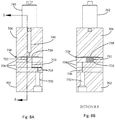
- FIGS. 8A and 8B show cross-sections of an assembled valve block 700 with seven inlet bores 710 and seven outlet bores 712 in accordance with an illustrative embodiment.
- FIG. 8A is a side perspective cross-section view of the valve block 700 shown in FIG. 7 .
- FIG. 8B is a side perspective cross-section of the valve block 700 shown in FIGS. 7 and 8A , with a cross section indicated by lines B-B in FIG. 8A .
- the valve blocks shown in FIGS. 8A and 8B can have the same elements configured in the same way as discussed above with reference to FIG. 7 .
- FIG. 9 shows a perspective view of an assembled valve block 700 with five inlet bores 710 and five outlet bores 712 in accordance with an illustrative embodiment.
- FIGS. 10A and 10B show cross-sections of an assembled valve block 700 with five inlet bores 710 and five outlet bores 712 in accordance with an illustrative embodiment.
- FIG. 10A is a side perspective cross-section view of the valve block 700 shown in FIG. 9 .
- FIG. 10B is a side perspective cross-section of the valve block 700 shown in FIGS. 9 and 10A , with a cross section indicated by lines B-B in FIG. 10A .
- the valve blocks shown in FIGS. 9 , 10A and 10B can have the same elements configured to operate in a similar fashion as discussed above with reference to FIG. 7 .
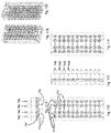
- FIGS. 11A - 11F show various views of an assembled valve block comprising multiple valves in accordance with an illustrative embodiment.
- a valve block with multiple valves can have varying configurations of inlet connection bore 730 and outlet connection bore 732 (and corresponding inlet channels 714 and outlet channels 716).
- the valve block can have inlet connection bores 730 that can provide a fluid inlet to multiple valves 742.
- FIG. 11D is a front view of the valve block and FIG. 11F is a rear view of the valve block.
- the valve block can have multiple outlet connection bores 732 that provide a fluid outlet for multiple valves.
- the inlet connection bore 730 can act as an outlet and the outlet connection bore 732 can act as an inlet.
- FIGS. 11B and 11C show a perspective view of the valve block with multiple valves and the various bores and channels corresponding to each valve in accordance with an illustrative embodiment.
- FIG. 11E shows a cut-away side perspective of a valve block with multiple valves in accordance with an illustrative embodiment.
- FIGS. 12A - 12G show various views of an assembled valve block comprising multiple valves in accordance with an illustrative embodiment.
- FIG. 12A shows a side perspective of the valve block.
- the valve block can have multiple gas valves 742 within the same valve block 700.
- FIG. 12F shows an embodiment of the bottom side of a fluid-transfer plate 704 that comprises five inlet bores 710 and five outlet bores 712 in accordance with an illustrative embodiment.
- the inlet bores 710 and the outlet bores 712 can be configured in an annular shape.
- FIG. 12A shows a side perspective of the valve block.
- the valve block can have multiple gas valves 742 within the same valve block 700.
- FIG. 12F shows an embodiment of the bottom side of a fluid-transfer plate 704 that comprises five inlet bores 710 and five outlet bores 712 in accordance with an illustrative embodiment.
- the inlet bores 710 and the outlet bores 712 can be configured in an
- FIGS. 12G and 12C show a view of pressure plate 706 with gas valves 742 in accordance with an illustrative embodiment.
- FIGS. 12B and 12C show perspective views of the outside surface of an assembled valve block comprising multiple valves in accordance with an illustrative embodiment.
Claims (12)
- Ventilblock (200, 700), umfassend:eine Druckplatte (120, 206, 706), umfassend eine Aussparung (122a, 122b, 218, 220, 718), die mit einem unter Druck stehenden Material an einer Oberseite der Druckplatte (120, 206, 706) gefüllt werden kann;eine Fluid-Übertragungsplatte (134, 204, 300, 704), umfassend einen Einlasskanal (302, 734), einen Auslasskanal (304, 736), eine Vielzahl von Einlassbohrungen (308, 400, 710), die sich von dem Einlasskanal zu einer Unterseite der Fluid-Übertragungsplatte erstrecken, und eine Vielzahl von Auslassbohrungen (312, 402, 712), die sich von dem Auslasskanal (304, 736) zu der Unterseite der Fluid-Übertragungsplatte (134, 204, 300, 704) erstrecken, wobei der Einlasskanal (302, 734), der Auslasskanal (304, 736), die Vielzahl von Einlassbohrungen (308, 400, 710) und die Vielzahl von Auslassbohrungen (312, 402, 712) in einem Ventil des Ventilblocks (200, 700) enthalten sind; undeine Membran (138, 602, 738), die zwischen der Oberseite der Druckplatte (120, 206, 706) und der Unterseite der Fluid-Übertragungsplatte (134, 204, 300, 704) angeordnet ist, wobei die Membran (138, 602, 738) konfiguriert ist, um einen Fluidstrom aus mindestens einer der Vielzahl von Einlassbohrungen (308, 400, 710) zu mindestens einer der Vielzahl von Auslassbohrungen (312, 402, 712) zu verhindern, wenn die Aussparung (122a, 122b, 218, 220, 718) mit unter Druck stehenden Material gefüllt ist; unddadurch gekennzeichnet, dass der Ventilblock (200, 700) ferner eine Abdeckplatte (136, 202, 702) umfasst, umfassend eine Einlassverbindungsbohrung (126, 128, 210, 730), die fluidisch mit dem Einlasskanal (302, 734) verbunden ist, und eine Auslassverbindungsbohrung (130, 132, 212, 732), die fluidisch mit dem Auslasskanal (304, 736) verbunden ist.
- Ventilblock (200, 700) nach Anspruch 1, wobei jede der Vielzahl von Einlassbohrungen (308, 400, 710) einen Durchmesser von höchstens 0,18 cm (0,070 Zoll) aufweist, und wobei jede der Vielzahl von Auslassbohrungen (312, 402, 712) einen Durchmesser von höchstens 0,18 cm (0,070 Zoll) aufweist.
- Ventilblock (200, 700) nach Anspruch 1, wobei jede der Vielzahl von Einlassbohrungen (308, 400, 710) einen Durchmesser von höchstens 0,24 cm (0,094 Zoll) aufweist, und wobei jede der Vielzahl von Auslassbohrungen (312, 402, 712) einen Durchmesser von höchstens 0,24 cm (0,094 Zoll) aufweist.
- Ventilblock (200, 700) nach Anspruch 2, wobei der Ventilblock (200, 700) ferner konfiguriert ist, um 2,5 Liter Fluid pro Minute durch die Vielzahl von Einlassbohrungen (308, 400, 710) bei einem Druckabfall von weniger als oder gleich wie 69 kPa (10 Pfund pro Quadratzoll) pro Ventil zu ermöglichen.
- Ventilblock (200, 700) nach Anspruch 4, wobei der Ventilblock (200, 700) ferner konfiguriert ist, um mit einer Temperatur des Fluids bei 65 Grad Celsius und einem Druck des Fluids bei bis zu 2070 kPa (300 Pfund pro Quadratzoll) betrieben zu werden.
- Ventilblock (200, 700) nach Anspruch 1, wobei ein Durchmesser der Vielzahl von Einlassbohrungen (308, 400, 710) konfiguriert ist, um eine dauerhafte Verformung der Membran (138, 602, 738) zu verhindern.
- Ventilblock (200, 700) nach Anspruch 6, wobei die dauerhafte Verformung der Membran (138, 602, 738) einem Druckabfall über die Vielzahl von Einlassbohrungen (308, 400, 710) und die Auslassbohrungen (312, 402, 712) von größer als oder gleich wie 69 kPa (zehn Pfund pro Quadratzoll) bei einer Durchflussrate von 2,5 Litern Wasser pro Minute entspricht.
- Ventilblock (200, 700) nach Anspruch 6, wobei die dauerhafte Verformung der Membran (138, 602, 738) einer Verformungshöhe der Membran (138, 602, 738) größer als oder gleich wie fünfunddreißig Prozent einer Stärke der Membran (138, 602, 738) entspricht.
- Ventilblock (200, 700) nach Anspruch 1, wobei eine Tiefe der Aussparung (122a, 122b, 218, 220, 718) zwischen 0,25 mm und 0,51 mm (0,010 Zoll und 0,020 Zoll) ist.
- Ventilblock (200, 700) nach Anspruch 1, wobei die Druckplatte (120, 206, 706) ferner eine Vielzahl von Aussparungen (220) umfasst, die mit dem unter Druck stehenden Material gefüllt werden können;
wobei jede der Vielzahl von Einlassbohrungen (308, 400, 710) einer anderen der Vielzahl von Auslassbohrungen (312, 402, 712) entspricht; und
wobei jede der Vielzahl von Aussparungen (220) konfiguriert ist, um einen Fluidstrom durch eine der Vielzahl von Einlassbohrungen (308, 400, 710) und die entsprechende andere der Vielzahl von Auslassbohrungen (312, 402, 712) zu regulieren. - Ventilblock (200, 700) nach Anspruch 10, wobei jede der Vielzahl von Aussparungen (220) unabhängig voneinander unter Druck gesetzt ist.
- Ventilblock (200, 700) nach Anspruch 1, wobei die Vielzahl von Einlassbohrungen (308, 400, 710) und die Vielzahl von Auslassbohrungen (312, 402, 712) in einer ringförmigen Form angeordnet sind.
Applications Claiming Priority (2)
| Application Number | Priority Date | Filing Date | Title |
|---|---|---|---|
| US201361914164P | 2013-12-10 | 2013-12-10 | |
| PCT/US2014/069580 WO2015089202A1 (en) | 2013-12-10 | 2014-12-10 | High-flow fluid valve block |
Publications (3)
| Publication Number | Publication Date |
|---|---|
| EP3094899A1 EP3094899A1 (de) | 2016-11-23 |
| EP3094899A4 EP3094899A4 (de) | 2017-08-02 |
| EP3094899B1 true EP3094899B1 (de) | 2019-04-10 |
Family
ID=53371810
Family Applications (3)
| Application Number | Title | Priority Date | Filing Date |
|---|---|---|---|
| EP14869509.1A Active EP3094899B1 (de) | 2013-12-10 | 2014-12-10 | Ventilblock mit hochstromflüssigkeit |
| EP15870643.2A Active EP3230632B1 (de) | 2013-12-10 | 2015-12-01 | Ventilblock mit hohem durchfluss |
| EP19209810.1A Pending EP3636973A1 (de) | 2013-12-10 | 2015-12-01 | Ventilblock mit hochstromflüssigkeit |
Family Applications After (2)
| Application Number | Title | Priority Date | Filing Date |
|---|---|---|---|
| EP15870643.2A Active EP3230632B1 (de) | 2013-12-10 | 2015-12-01 | Ventilblock mit hohem durchfluss |
| EP19209810.1A Pending EP3636973A1 (de) | 2013-12-10 | 2015-12-01 | Ventilblock mit hochstromflüssigkeit |
Country Status (7)
| Country | Link |
|---|---|
| US (8) | US10393276B2 (de) |
| EP (3) | EP3094899B1 (de) |
| JP (3) | JP6689278B2 (de) |
| CN (1) | CN107407434B (de) |
| CA (1) | CA3008014C (de) |
| HK (2) | HK1231537A1 (de) |
| WO (2) | WO2015089202A1 (de) |
Families Citing this family (6)
| Publication number | Priority date | Publication date | Assignee | Title |
|---|---|---|---|---|
| WO2015089202A1 (en) | 2013-12-10 | 2015-06-18 | Semba Biosciences, Inc. | High-flow fluid valve block |
| CN104653837B (zh) * | 2015-02-16 | 2017-10-03 | 艾欧史密斯(中国)热水器有限公司 | 比例阀阀体的加工方法 |
| JP6430983B2 (ja) * | 2016-03-23 | 2018-11-28 | トヨタ自動車株式会社 | バルブ装置 |
| JP7157461B2 (ja) * | 2017-10-31 | 2022-10-20 | 株式会社フジキン | バルブ装置 |
| US11426730B2 (en) * | 2020-02-24 | 2022-08-30 | Merck Sharp & Dohme Corp. | Well plate assembly with pressure release mechanism |
| CN114688296B (zh) * | 2020-12-29 | 2023-05-16 | 上海微电子装备(集团)股份有限公司 | 气动控制装置及系统、光刻设备 |
Family Cites Families (45)
| Publication number | Priority date | Publication date | Assignee | Title |
|---|---|---|---|---|
| US2877791A (en) | 1955-08-15 | 1959-03-17 | Fisher Governor Co | Flexible diaphragm flow control valve |
| US3792720A (en) | 1970-11-27 | 1974-02-19 | Sybron Corp | Diaphragm valve |
| US3856046A (en) * | 1972-10-17 | 1974-12-24 | Tool Instr Ass Inc | Valve |
| US3844529A (en) | 1973-05-11 | 1974-10-29 | Brandt Ind | Fluid valve having a pressure responsive internal membrane |
| DE2648751C2 (de) | 1976-10-27 | 1986-04-30 | Max-Planck-Gesellschaft zur Förderung der Wissenschaften e.V., 3400 Göttingen | Vorrichtung für die Zuführung flüssiger oder gasförmiger Substanzen zu einem Verarbeitungsgefäß |
| US4119120A (en) | 1976-11-29 | 1978-10-10 | Beckman Instruments, Inc. | Fluid switch |
| US4098490A (en) | 1977-03-02 | 1978-07-04 | Acf Industries, Incorporated | Valve body-bonnet joint |
| DE2821801C3 (de) * | 1978-05-19 | 1981-06-25 | Friedrich Wilhelm 6535 Gau-Algesheim Schmitt | Ventilanordnung mit Membranventilen |
| US4353243A (en) | 1981-02-02 | 1982-10-12 | Quadrex Corporation | Flexible diaphragm controlled valve |
| US4431019A (en) | 1981-06-25 | 1984-02-14 | Baxter Travenol Laboratories, Inc. | Fluid flow control device |
| JPS5891067U (ja) | 1981-12-15 | 1983-06-20 | 三菱重工業株式会社 | 大容量切換弁 |
| US4558845A (en) | 1982-09-22 | 1985-12-17 | Hunkapiller Michael W | Zero dead volume valve |
| JPS62100380U (de) * | 1985-12-16 | 1987-06-26 | ||
| US5088515A (en) | 1989-05-01 | 1992-02-18 | Kamen Dean L | Valve system with removable fluid interface |
| JP2525772B2 (ja) * | 1986-05-19 | 1996-08-21 | 藤倉ゴム工業株式会社 | ダイアフラム型パイロツト操作方向切換弁 |
| US4852851A (en) | 1987-12-11 | 1989-08-01 | Integrated Fluidics, Inc. | Valve with flexible sheet member |
| US4858883A (en) * | 1987-12-11 | 1989-08-22 | Integrated Fluidics, Inc. | Valve with flexible sheet member |
| US4846215A (en) | 1988-06-07 | 1989-07-11 | Marathon Oil Company | Back pressure regulator |
| US4917348A (en) * | 1988-11-14 | 1990-04-17 | Oden Corporation | Filling nozzle cut-off valve |
| CN1023509C (zh) | 1989-04-28 | 1994-01-12 | 里希尔国际有限公司 | 阀组件 |
| US5176359A (en) * | 1991-05-20 | 1993-01-05 | Photovac International, Inc. | Fluid control valve arrangement |
| US5271601A (en) * | 1992-07-29 | 1993-12-21 | Fisher Controls International, Inc. | Regulator valve with diaphragm support |
| US5496009A (en) | 1994-10-07 | 1996-03-05 | Bayer Corporation | Valve |
| US5660370A (en) | 1996-03-07 | 1997-08-26 | Integrated Fludics, Inc. | Valve with flexible sheet member and two port non-flexing backer member |
| JP3029515U (ja) * | 1996-03-27 | 1996-10-01 | 株式会社ベンカン | ダイヤフラム弁のシート交換式弁座構造 |
| US6698915B2 (en) * | 2001-12-26 | 2004-03-02 | Rolligon Corporation | Manifold for mixing device |
| US6834675B1 (en) | 2003-08-06 | 2004-12-28 | Ajit Singh Gill | Integrated multipurpose caged valve |
| ATE394726T1 (de) * | 2004-03-12 | 2008-05-15 | Hengst Gmbh & Co Kg | Pneumatisches druckregelventil |
| US7544293B2 (en) | 2005-09-26 | 2009-06-09 | Semba Inc. | Valve and process for interrupted continuous flow chromatography |
| US20070128061A1 (en) | 2005-12-02 | 2007-06-07 | Iraj Gashgaee | Fixed volume valve system |
| US7790040B2 (en) | 2006-08-30 | 2010-09-07 | Semba Biosciences, Inc. | Continuous isocratic affinity chromatography |
| US8807164B2 (en) | 2006-08-30 | 2014-08-19 | Semba Biosciences, Inc. | Valve module and methods for simulated moving bed chromatography |
| US7806137B2 (en) | 2006-08-30 | 2010-10-05 | Semba Biosciences, Inc. | Control system for simulated moving bed chromatography |
| US7607641B1 (en) | 2006-10-05 | 2009-10-27 | Microfluidic Systems, Inc. | Microfluidic valve mechanism |
| EP2003379A1 (de) | 2007-06-12 | 2008-12-17 | Luxembourg Patent Company S.A. | Hochdruckmembranventil mit austauschbarer Sitzanordnung |
| FR2918148A1 (fr) * | 2007-06-29 | 2009-01-02 | Witeck Sarl | Bloc de distribution de fluides. |
| US8104506B2 (en) | 2007-07-10 | 2012-01-31 | Mecanique Analytique Inc. | Diaphragm-sealed valve having intermediate communication ports |
| US8193280B2 (en) * | 2008-07-04 | 2012-06-05 | Az Technology, Inc. | Ionic liquid epoxy resins |
| US8196603B2 (en) * | 2008-08-20 | 2012-06-12 | Semba Biosciences, Inc. | Valve block assembly |
| JP5343611B2 (ja) | 2009-02-23 | 2013-11-13 | セイコーエプソン株式会社 | 圧力調整弁およびこれを備えた液滴吐出装置 |
| US8844901B2 (en) * | 2009-03-27 | 2014-09-30 | Horiba Stec, Co., Ltd. | Flow control valve |
| CN201526718U (zh) | 2009-11-04 | 2010-07-14 | 山东中石大石仪科技有限公司 | 带有柔性隔离环和过滤挡片的回压器 |
| EP2724060B1 (de) * | 2011-06-24 | 2019-11-27 | Equilibar, LLC | Gegendruckregler mit gleitringdichtungsträger |
| JP5891067B2 (ja) | 2012-02-28 | 2016-03-22 | Kddi株式会社 | 通信制御装置および通信制御方法 |
| WO2015089202A1 (en) | 2013-12-10 | 2015-06-18 | Semba Biosciences, Inc. | High-flow fluid valve block |
-
2014
- 2014-12-10 WO PCT/US2014/069580 patent/WO2015089202A1/en active Application Filing
- 2014-12-10 EP EP14869509.1A patent/EP3094899B1/de active Active
- 2014-12-10 US US15/102,989 patent/US10393276B2/en active Active
-
2015
- 2015-12-01 CN CN201580075570.XA patent/CN107407434B/zh active Active
- 2015-12-01 JP JP2017531619A patent/JP6689278B2/ja active Active
- 2015-12-01 CA CA3008014A patent/CA3008014C/en active Active
- 2015-12-01 EP EP15870643.2A patent/EP3230632B1/de active Active
- 2015-12-01 US US15/534,369 patent/US10451188B2/en active Active
- 2015-12-01 WO PCT/US2015/063109 patent/WO2016099857A1/en active Application Filing
- 2015-12-01 EP EP19209810.1A patent/EP3636973A1/de active Pending
-
2017
- 2017-05-23 HK HK17105208.8A patent/HK1231537A1/zh unknown
-
2018
- 2018-04-17 HK HK18104954.6A patent/HK1245380A1/zh unknown
-
2019
- 2019-08-26 US US16/550,550 patent/US11054045B2/en active Active
- 2019-10-18 US US16/657,670 patent/US11174952B2/en active Active
-
2020
- 2020-04-07 JP JP2020068824A patent/JP6994697B2/ja active Active
-
2021
- 2021-06-04 US US17/338,934 patent/US11703133B2/en active Active
- 2021-11-15 US US17/526,465 patent/US11773989B2/en active Active
- 2021-12-01 JP JP2021195182A patent/JP7446272B2/ja active Active
-
2023
- 2023-05-11 US US18/196,321 patent/US20230358322A1/en active Pending
- 2023-08-29 US US18/457,977 patent/US20230400106A1/en active Pending
Non-Patent Citations (1)
| Title |
|---|
| None * |
Also Published As
Similar Documents
| Publication | Publication Date | Title |
|---|---|---|
| US11703133B2 (en) | High-flow fluid valve block | |
| EP2334397B1 (de) | Ventilblockanordnung | |
| CN102812276B (zh) | 微阀 | |
| CN107250648B (zh) | 具有自动压力补偿的脉冲阻尼器 | |
| JP7308192B2 (ja) | ダイヤフラム式チェックバルブ | |
| EP3033526B1 (de) | Mikrofluidische vorrichtung mit ventil | |
| JP4303177B2 (ja) | 薬液弁 | |
| US20160319958A1 (en) | Multiplexed valve for microfluidic devices | |
| EP3464967A1 (de) | Ventilbaugruppe und verfahren zum betrieb davon | |
| KR101566678B1 (ko) | 유체 제어 통합형 밸브 블럭 | |
| JP2003254454A (ja) | パターン式流路切換え微小弁 |
Legal Events
| Date | Code | Title | Description |
|---|---|---|---|
| PUAI | Public reference made under article 153(3) epc to a published international application that has entered the european phase |
Free format text: ORIGINAL CODE: 0009012 |
|
| 17P | Request for examination filed |
Effective date: 20160706 |
|
| AK | Designated contracting states |
Kind code of ref document: A1 Designated state(s): AL AT BE BG CH CY CZ DE DK EE ES FI FR GB GR HR HU IE IS IT LI LT LU LV MC MK MT NL NO PL PT RO RS SE SI SK SM TR |
|
| AX | Request for extension of the european patent |
Extension state: BA ME |
|
| DAX | Request for extension of the european patent (deleted) | ||
| A4 | Supplementary search report drawn up and despatched |
Effective date: 20170704 |
|
| RIC1 | Information provided on ipc code assigned before grant |
Ipc: F16K 31/126 20060101ALI20170628BHEP Ipc: F16K 7/17 20060101AFI20170628BHEP |
|
| REG | Reference to a national code |
Ref country code: HK Ref legal event code: DE Ref document number: 1231537 Country of ref document: HK |
|
| STAA | Information on the status of an ep patent application or granted ep patent |
Free format text: STATUS: EXAMINATION IS IN PROGRESS |
|
| 17Q | First examination report despatched |
Effective date: 20180323 |
|
| REG | Reference to a national code |
Ref country code: DE Ref legal event code: R079 Ref document number: 602014044673 Country of ref document: DE Free format text: PREVIOUS MAIN CLASS: F16K0007170000 Ipc: F16K0011044000 |
|
| RIC1 | Information provided on ipc code assigned before grant |
Ipc: F16K 11/044 20060101AFI20180911BHEP |
|
| GRAP | Despatch of communication of intention to grant a patent |
Free format text: ORIGINAL CODE: EPIDOSNIGR1 |
|
| STAA | Information on the status of an ep patent application or granted ep patent |
Free format text: STATUS: GRANT OF PATENT IS INTENDED |
|
| INTG | Intention to grant announced |
Effective date: 20181024 |
|
| GRAS | Grant fee paid |
Free format text: ORIGINAL CODE: EPIDOSNIGR3 |
|
| GRAA | (expected) grant |
Free format text: ORIGINAL CODE: 0009210 |
|
| STAA | Information on the status of an ep patent application or granted ep patent |
Free format text: STATUS: THE PATENT HAS BEEN GRANTED |
|
| AK | Designated contracting states |
Kind code of ref document: B1 Designated state(s): AL AT BE BG CH CY CZ DE DK EE ES FI FR GB GR HR HU IE IS IT LI LT LU LV MC MK MT NL NO PL PT RO RS SE SI SK SM TR |
|
| REG | Reference to a national code |
Ref country code: GB Ref legal event code: FG4D |
|
| REG | Reference to a national code |
Ref country code: CH Ref legal event code: EP Ref country code: AT Ref legal event code: REF Ref document number: 1119124 Country of ref document: AT Kind code of ref document: T Effective date: 20190415 |
|
| REG | Reference to a national code |
Ref country code: IE Ref legal event code: FG4D |
|
| REG | Reference to a national code |
Ref country code: DE Ref legal event code: R096 Ref document number: 602014044673 Country of ref document: DE |
|
| REG | Reference to a national code |
Ref country code: NL Ref legal event code: MP Effective date: 20190410 |
|
| REG | Reference to a national code |
Ref country code: LT Ref legal event code: MG4D |
|
| REG | Reference to a national code |
Ref country code: AT Ref legal event code: MK05 Ref document number: 1119124 Country of ref document: AT Kind code of ref document: T Effective date: 20190410 |
|
| PG25 | Lapsed in a contracting state [announced via postgrant information from national office to epo] |
Ref country code: NL Free format text: LAPSE BECAUSE OF FAILURE TO SUBMIT A TRANSLATION OF THE DESCRIPTION OR TO PAY THE FEE WITHIN THE PRESCRIBED TIME-LIMIT Effective date: 20190410 |
|
| PG25 | Lapsed in a contracting state [announced via postgrant information from national office to epo] |
Ref country code: LT Free format text: LAPSE BECAUSE OF FAILURE TO SUBMIT A TRANSLATION OF THE DESCRIPTION OR TO PAY THE FEE WITHIN THE PRESCRIBED TIME-LIMIT Effective date: 20190410 Ref country code: HR Free format text: LAPSE BECAUSE OF FAILURE TO SUBMIT A TRANSLATION OF THE DESCRIPTION OR TO PAY THE FEE WITHIN THE PRESCRIBED TIME-LIMIT Effective date: 20190410 Ref country code: SE Free format text: LAPSE BECAUSE OF FAILURE TO SUBMIT A TRANSLATION OF THE DESCRIPTION OR TO PAY THE FEE WITHIN THE PRESCRIBED TIME-LIMIT Effective date: 20190410 Ref country code: PT Free format text: LAPSE BECAUSE OF FAILURE TO SUBMIT A TRANSLATION OF THE DESCRIPTION OR TO PAY THE FEE WITHIN THE PRESCRIBED TIME-LIMIT Effective date: 20190910 Ref country code: NO Free format text: LAPSE BECAUSE OF FAILURE TO SUBMIT A TRANSLATION OF THE DESCRIPTION OR TO PAY THE FEE WITHIN THE PRESCRIBED TIME-LIMIT Effective date: 20190710 Ref country code: ES Free format text: LAPSE BECAUSE OF FAILURE TO SUBMIT A TRANSLATION OF THE DESCRIPTION OR TO PAY THE FEE WITHIN THE PRESCRIBED TIME-LIMIT Effective date: 20190410 Ref country code: AL Free format text: LAPSE BECAUSE OF FAILURE TO SUBMIT A TRANSLATION OF THE DESCRIPTION OR TO PAY THE FEE WITHIN THE PRESCRIBED TIME-LIMIT Effective date: 20190410 Ref country code: FI Free format text: LAPSE BECAUSE OF FAILURE TO SUBMIT A TRANSLATION OF THE DESCRIPTION OR TO PAY THE FEE WITHIN THE PRESCRIBED TIME-LIMIT Effective date: 20190410 |
|
| PG25 | Lapsed in a contracting state [announced via postgrant information from national office to epo] |
Ref country code: BG Free format text: LAPSE BECAUSE OF FAILURE TO SUBMIT A TRANSLATION OF THE DESCRIPTION OR TO PAY THE FEE WITHIN THE PRESCRIBED TIME-LIMIT Effective date: 20190710 Ref country code: GR Free format text: LAPSE BECAUSE OF FAILURE TO SUBMIT A TRANSLATION OF THE DESCRIPTION OR TO PAY THE FEE WITHIN THE PRESCRIBED TIME-LIMIT Effective date: 20190711 Ref country code: LV Free format text: LAPSE BECAUSE OF FAILURE TO SUBMIT A TRANSLATION OF THE DESCRIPTION OR TO PAY THE FEE WITHIN THE PRESCRIBED TIME-LIMIT Effective date: 20190410 Ref country code: RS Free format text: LAPSE BECAUSE OF FAILURE TO SUBMIT A TRANSLATION OF THE DESCRIPTION OR TO PAY THE FEE WITHIN THE PRESCRIBED TIME-LIMIT Effective date: 20190410 Ref country code: PL Free format text: LAPSE BECAUSE OF FAILURE TO SUBMIT A TRANSLATION OF THE DESCRIPTION OR TO PAY THE FEE WITHIN THE PRESCRIBED TIME-LIMIT Effective date: 20190410 |
|
| PG25 | Lapsed in a contracting state [announced via postgrant information from national office to epo] |
Ref country code: AT Free format text: LAPSE BECAUSE OF FAILURE TO SUBMIT A TRANSLATION OF THE DESCRIPTION OR TO PAY THE FEE WITHIN THE PRESCRIBED TIME-LIMIT Effective date: 20190410 Ref country code: IS Free format text: LAPSE BECAUSE OF FAILURE TO SUBMIT A TRANSLATION OF THE DESCRIPTION OR TO PAY THE FEE WITHIN THE PRESCRIBED TIME-LIMIT Effective date: 20190810 |
|
| REG | Reference to a national code |
Ref country code: DE Ref legal event code: R097 Ref document number: 602014044673 Country of ref document: DE |
|
| PG25 | Lapsed in a contracting state [announced via postgrant information from national office to epo] |
Ref country code: SK Free format text: LAPSE BECAUSE OF FAILURE TO SUBMIT A TRANSLATION OF THE DESCRIPTION OR TO PAY THE FEE WITHIN THE PRESCRIBED TIME-LIMIT Effective date: 20190410 Ref country code: CZ Free format text: LAPSE BECAUSE OF FAILURE TO SUBMIT A TRANSLATION OF THE DESCRIPTION OR TO PAY THE FEE WITHIN THE PRESCRIBED TIME-LIMIT Effective date: 20190410 Ref country code: RO Free format text: LAPSE BECAUSE OF FAILURE TO SUBMIT A TRANSLATION OF THE DESCRIPTION OR TO PAY THE FEE WITHIN THE PRESCRIBED TIME-LIMIT Effective date: 20190410 Ref country code: DK Free format text: LAPSE BECAUSE OF FAILURE TO SUBMIT A TRANSLATION OF THE DESCRIPTION OR TO PAY THE FEE WITHIN THE PRESCRIBED TIME-LIMIT Effective date: 20190410 Ref country code: EE Free format text: LAPSE BECAUSE OF FAILURE TO SUBMIT A TRANSLATION OF THE DESCRIPTION OR TO PAY THE FEE WITHIN THE PRESCRIBED TIME-LIMIT Effective date: 20190410 |
|
| PLBE | No opposition filed within time limit |
Free format text: ORIGINAL CODE: 0009261 |
|
| STAA | Information on the status of an ep patent application or granted ep patent |
Free format text: STATUS: NO OPPOSITION FILED WITHIN TIME LIMIT |
|
| PG25 | Lapsed in a contracting state [announced via postgrant information from national office to epo] |
Ref country code: SM Free format text: LAPSE BECAUSE OF FAILURE TO SUBMIT A TRANSLATION OF THE DESCRIPTION OR TO PAY THE FEE WITHIN THE PRESCRIBED TIME-LIMIT Effective date: 20190410 Ref country code: IT Free format text: LAPSE BECAUSE OF FAILURE TO SUBMIT A TRANSLATION OF THE DESCRIPTION OR TO PAY THE FEE WITHIN THE PRESCRIBED TIME-LIMIT Effective date: 20190410 |
|
| 26N | No opposition filed |
Effective date: 20200113 |
|
| PG25 | Lapsed in a contracting state [announced via postgrant information from national office to epo] |
Ref country code: TR Free format text: LAPSE BECAUSE OF FAILURE TO SUBMIT A TRANSLATION OF THE DESCRIPTION OR TO PAY THE FEE WITHIN THE PRESCRIBED TIME-LIMIT Effective date: 20190410 |
|
| PG25 | Lapsed in a contracting state [announced via postgrant information from national office to epo] |
Ref country code: SI Free format text: LAPSE BECAUSE OF FAILURE TO SUBMIT A TRANSLATION OF THE DESCRIPTION OR TO PAY THE FEE WITHIN THE PRESCRIBED TIME-LIMIT Effective date: 20190410 |
|
| REG | Reference to a national code |
Ref country code: CH Ref legal event code: PL |
|
| REG | Reference to a national code |
Ref country code: BE Ref legal event code: MM Effective date: 20191231 |
|
| PG25 | Lapsed in a contracting state [announced via postgrant information from national office to epo] |
Ref country code: MC Free format text: LAPSE BECAUSE OF FAILURE TO SUBMIT A TRANSLATION OF THE DESCRIPTION OR TO PAY THE FEE WITHIN THE PRESCRIBED TIME-LIMIT Effective date: 20190410 |
|
| PG25 | Lapsed in a contracting state [announced via postgrant information from national office to epo] |
Ref country code: IE Free format text: LAPSE BECAUSE OF NON-PAYMENT OF DUE FEES Effective date: 20191210 Ref country code: LU Free format text: LAPSE BECAUSE OF NON-PAYMENT OF DUE FEES Effective date: 20191210 |
|
| PG25 | Lapsed in a contracting state [announced via postgrant information from national office to epo] |
Ref country code: BE Free format text: LAPSE BECAUSE OF NON-PAYMENT OF DUE FEES Effective date: 20191231 Ref country code: CH Free format text: LAPSE BECAUSE OF NON-PAYMENT OF DUE FEES Effective date: 20191231 Ref country code: LI Free format text: LAPSE BECAUSE OF NON-PAYMENT OF DUE FEES Effective date: 20191231 |
|
| PG25 | Lapsed in a contracting state [announced via postgrant information from national office to epo] |
Ref country code: CY Free format text: LAPSE BECAUSE OF FAILURE TO SUBMIT A TRANSLATION OF THE DESCRIPTION OR TO PAY THE FEE WITHIN THE PRESCRIBED TIME-LIMIT Effective date: 20190410 |
|
| PG25 | Lapsed in a contracting state [announced via postgrant information from national office to epo] |
Ref country code: HU Free format text: LAPSE BECAUSE OF FAILURE TO SUBMIT A TRANSLATION OF THE DESCRIPTION OR TO PAY THE FEE WITHIN THE PRESCRIBED TIME-LIMIT; INVALID AB INITIO Effective date: 20141210 Ref country code: MT Free format text: LAPSE BECAUSE OF FAILURE TO SUBMIT A TRANSLATION OF THE DESCRIPTION OR TO PAY THE FEE WITHIN THE PRESCRIBED TIME-LIMIT Effective date: 20190410 |
|
| PG25 | Lapsed in a contracting state [announced via postgrant information from national office to epo] |
Ref country code: MK Free format text: LAPSE BECAUSE OF FAILURE TO SUBMIT A TRANSLATION OF THE DESCRIPTION OR TO PAY THE FEE WITHIN THE PRESCRIBED TIME-LIMIT Effective date: 20190410 |
|
| REG | Reference to a national code |
Ref country code: GB Ref legal event code: 732E Free format text: REGISTERED BETWEEN 20230209 AND 20230215 |
|
| REG | Reference to a national code |
Ref country code: DE Ref legal event code: R081 Ref document number: 602014044673 Country of ref document: DE Owner name: TOSOH BIOSCIENCE LLC, KING OF PRUSSIA, US Free format text: FORMER OWNER: SEMBA BIOSCIENCES, INC., MADISON, WIS., US |
|
| REG | Reference to a national code |
Ref country code: DE Ref legal event code: R081 Ref document number: 602014044673 Country of ref document: DE Owner name: TOSOH BIOSCIENCE LLC, KING OF PRUSSIA, US Free format text: FORMER OWNER: TOSOH BIOSEIENCE LLC, KING OF PRUSSIA, PA, US |
|
| PGFP | Annual fee paid to national office [announced via postgrant information from national office to epo] |
Ref country code: FR Payment date: 20230124 Year of fee payment: 9 |
|
| PGFP | Annual fee paid to national office [announced via postgrant information from national office to epo] |
Ref country code: GB Payment date: 20230119 Year of fee payment: 9 Ref country code: DE Payment date: 20230123 Year of fee payment: 9 |
|
| P01 | Opt-out of the competence of the unified patent court (upc) registered |
Effective date: 20230413 |