EP3094882B1 - Multi-state electronically switchable engine mount assembly - Google Patents
Multi-state electronically switchable engine mount assembly Download PDFInfo
- Publication number
- EP3094882B1 EP3094882B1 EP14876084.6A EP14876084A EP3094882B1 EP 3094882 B1 EP3094882 B1 EP 3094882B1 EP 14876084 A EP14876084 A EP 14876084A EP 3094882 B1 EP3094882 B1 EP 3094882B1
- Authority
- EP
- European Patent Office
- Prior art keywords
- port
- idle
- assembly
- decoupler
- fluid
- Prior art date
- Legal status (The legal status is an assumption and is not a legal conclusion. Google has not performed a legal analysis and makes no representation as to the accuracy of the status listed.)
- Active
Links
Images



Classifications
-
- F—MECHANICAL ENGINEERING; LIGHTING; HEATING; WEAPONS; BLASTING
- F16—ENGINEERING ELEMENTS AND UNITS; GENERAL MEASURES FOR PRODUCING AND MAINTAINING EFFECTIVE FUNCTIONING OF MACHINES OR INSTALLATIONS; THERMAL INSULATION IN GENERAL
- F16F—SPRINGS; SHOCK-ABSORBERS; MEANS FOR DAMPING VIBRATION
- F16F13/00—Units comprising springs of the non-fluid type as well as vibration-dampers, shock-absorbers, or fluid springs
- F16F13/04—Units comprising springs of the non-fluid type as well as vibration-dampers, shock-absorbers, or fluid springs comprising both a plastics spring and a damper, e.g. a friction damper
- F16F13/26—Units comprising springs of the non-fluid type as well as vibration-dampers, shock-absorbers, or fluid springs comprising both a plastics spring and a damper, e.g. a friction damper characterised by adjusting or regulating devices responsive to exterior conditions
-
- B—PERFORMING OPERATIONS; TRANSPORTING
- B60—VEHICLES IN GENERAL
- B60K—ARRANGEMENT OR MOUNTING OF PROPULSION UNITS OR OF TRANSMISSIONS IN VEHICLES; ARRANGEMENT OR MOUNTING OF PLURAL DIVERSE PRIME-MOVERS IN VEHICLES; AUXILIARY DRIVES FOR VEHICLES; INSTRUMENTATION OR DASHBOARDS FOR VEHICLES; ARRANGEMENTS IN CONNECTION WITH COOLING, AIR INTAKE, GAS EXHAUST OR FUEL SUPPLY OF PROPULSION UNITS IN VEHICLES
- B60K5/00—Arrangement or mounting of internal-combustion or jet-propulsion units
- B60K5/12—Arrangement of engine supports
- B60K5/1283—Adjustable supports, e.g. the mounting or the characteristics being adjustable
-
- F—MECHANICAL ENGINEERING; LIGHTING; HEATING; WEAPONS; BLASTING
- F16—ENGINEERING ELEMENTS AND UNITS; GENERAL MEASURES FOR PRODUCING AND MAINTAINING EFFECTIVE FUNCTIONING OF MACHINES OR INSTALLATIONS; THERMAL INSULATION IN GENERAL
- F16F—SPRINGS; SHOCK-ABSORBERS; MEANS FOR DAMPING VIBRATION
- F16F13/00—Units comprising springs of the non-fluid type as well as vibration-dampers, shock-absorbers, or fluid springs
- F16F13/04—Units comprising springs of the non-fluid type as well as vibration-dampers, shock-absorbers, or fluid springs comprising both a plastics spring and a damper, e.g. a friction damper
- F16F13/06—Units comprising springs of the non-fluid type as well as vibration-dampers, shock-absorbers, or fluid springs comprising both a plastics spring and a damper, e.g. a friction damper the damper being a fluid damper, e.g. the plastics spring not forming a part of the wall of the fluid chamber of the damper
- F16F13/08—Units comprising springs of the non-fluid type as well as vibration-dampers, shock-absorbers, or fluid springs comprising both a plastics spring and a damper, e.g. a friction damper the damper being a fluid damper, e.g. the plastics spring not forming a part of the wall of the fluid chamber of the damper the plastics spring forming at least a part of the wall of the fluid chamber of the damper
- F16F13/10—Units comprising springs of the non-fluid type as well as vibration-dampers, shock-absorbers, or fluid springs comprising both a plastics spring and a damper, e.g. a friction damper the damper being a fluid damper, e.g. the plastics spring not forming a part of the wall of the fluid chamber of the damper the plastics spring forming at least a part of the wall of the fluid chamber of the damper the wall being at least in part formed by a flexible membrane or the like
Definitions
- This disclosure relates to a damper assembly and specifically a multistage switchable inertia track assembly.
- Automotive engineers frequently use hydraulically damped elastomeric powertrain mounts to control shake and vibration responses resulting from various sources such as road inputs.
- the pumped fluid oscillates through a tube called an inertia track which creates a fluid resonance system and associated damping to dissipate the vibration energy and reduce the shake response.
- This bypass valve usually takes the form of a simple rubber disc or other flat shape, fitted between two perforated rigid forms, such as pierced metal plates, which is positioned to provide a short, direct route to the low pressure reservoir. Clearance between the thickness of the disc and the spacing of the perforated plates permits unimpeded flow between the pump chamber and low pressure reservoir for small vibration inputs, while effectively sealing the pathway and forcing the fluid to flow through the inertia track during high amplitude vibration.
- the disc or other shape that redirects fluid flow depending on the amplitude of the vibration input is referred to as the decoupler.
- the air in the volume acts as a stiff spring because the volume is closed or sealed and the damping fluid is transferred back and forth between a first or working fluid chamber and a second or compensating fluid chamber to damp high amplitude, low frequency vibrations.
- the air spring (closed volume) created by the closed port reduces the pressure of the fluid that would otherwise be pumped through the inertia track, as some of the fluid pressure is used to compress the air spring.
- this mount is intended to suspend the powertrain, provide damping to powertrain motion, control the powertrain travel, and isolate the powertrain from the vehicle chassis.
- the switch mechanisms in multi-state mounts allow the mount to switch among four states. Two of the states allow the fluid effect of the mount to be decoupled from compliance vibrations, and the other two states adjust the damping and frequency response of the mount.
- a prior art switchable engine mount assembly including the features set out in the preamble of claim 1, is disclosed in patent US 2011/0024960 A1 .
- a multistate electronically switchable engine mount assembly comprising: a housing; an inertia track received in the housing and having an elongated fluid damped first path that is adapted to communicate with an associated first fluid chamber on a first side and an associated second fluid chamber on a second side, and a non-damped second path that is adapted to communicate with the associated first and second fluid chambers; a decoupler; an idle diaphragm in the housing that selectively controls communication between the first and second fluid chambers to selectively alter the damping; first idle and second decoupler ports in the housing that communicate with the idle diaphragm and the decoupler, respectively; a first solenoid that selectively controls fluid flow through the first idle port; and a second solenoid that selectively controls fluid flow through the second decoupler port, characterised in that the first solenoid is larger than the second solenoid.
- the assembly In the absence of electrical power, the assembly operates as a decoupled hydromount.
- the first solenoid is an idle fluid port and the second solenoid is a decoupler air port.
- the first port is normally closed and the second port is normally open.
- the diaphragm includes a first opening therethrough.
- the first opening is aligned with the second solenoid.
- the inertia track includes an elongated air port member extending through the first opening in the diaphragm that communicates with the decoupler.
- a diaphragm cover interposed between the diaphragm and the first and second solenoids.
- the diaphragm cover includes a support that receives a terminal end of the elongated air port member for aligning the terminal end with the second solenoid.
- a moveable valve controls flow through the idle port in the inertia track.
- a biasing spring urges the valve to a normally closed position with the idle port.
- a method of making an engine mount comprising: providing a housing; positioning an inertia track in the housing that has an elongated fluid damped first path that is adapted to communicate with an associated first fluid chamber on a first side and an associated second fluid chamber on a second side, and a non-damped second path that is adapted to communicate with the associated first and second fluid chambers; providing a decoupler in the housing to selectively close at least one of the first and second paths; supplying a diaphragm in the housing to selectively control communication between the first and second fluid chambers and to selectively alter the damping state; providing first and second ports in the housing to communicate with the idle diaphragm and the decoupler, respectively; and providing first and second solenoids that control fluid flow through the first and second ports, respectively, characterised in that the method includes making the first solenoid larger than the second solenoid.
- the mount assembly 100 includes a restrictor or external housing 102 dimensioned to receive a first or elastomeric component or main rubber element 104 that is generally shaped as a truncated cone, and primarily made of an elastomeric material, such as an elastic rubber as is conventional in the art.
- a fastener or bolt 106 extends outwardly from the main rubber element 104 for fastening to a power train or engine (not shown) in a manner generally known in the art.
- the fastener 106 cooperates with a metal bearing member 108 ( Figure 3 ) that has at least a portion encapsulated within the first elastomeric member 104.
- a lower peripheral portion of the main rubber element 104 may include a stiffener, such as metallic stiffener 110, molded within the main rubber element to add rigidity and support.
- the main rubber element 104 is received within the restrictor housing 102 so that the fastener 106 extends through a central opening 112 in the restrictor.
- An internal shoulder 114 ( Figure 3 ) of the restrictor 102 abuttingly engages the reinforced, lower portion of the main rubber element 104.
- the lower portion of the main rubber element 104 forms a portion of a first or upper fluid chamber 116, namely a high pressure side, of the engine mount 100.
- the remainder of the first fluid chamber 116 is defined by an inertia track assembly 120, more specific details of which will be described below.
- An outer radial portion of an upper surface of the inertia track assembly denoted by reference numeral 122 abuttingly and sealingly engages the main rubber element 104 in order to seal the first fluid chamber 116.
- at least a portion of the inertia track assembly 120 is received within the restrictor housing 102.
- a second, outer radial portion along the lower surface denoted by reference numeral 124 is sealingly engaged by a rubber boot or diaphragm 130, and particularly an upper peripheral portion 132 thereof.
- the diaphragm 130 includes an opening 134 therethrough for reasons to be described further below.
- the diaphragm 130 is protected by a diaphragm cover 140, preferably formed of a more rigid material than the elastomeric diaphragm, and that matingly engages the restrictor housing 102.
- a diaphragm cover 140 When the diaphragm cover 140 is fastened to the restrictor 102, the lower peripheral edge of the main rubber element 104 and the peripheral portion 132 of the diaphragm sealingly engage opposite sides or faces 122, 124, respectively, of the inertia track assembly 120.
- the inertia track assembly 120 is disposed between the first or upper fluid chamber 116 and the second or lower fluid chamber 150.
- the upper side of the inertia track assembly 120 is associated with the high pressure side of the mount.
- the lower surface of the inertia track assembly 120 is associated with the second or lower fluid chamber 150 and is sometimes referred to as the low pressure side of the mount.
- the fluid is pumped from the top to the bottom through the inertia track assembly 120.
- the fluid response of the inertia track assembly 120 depends on a decoupler 160 and the diaphragm 130.
- the diaphragm 130 is sealed about its perimeter to an underside of the inertia track assembly 120, thus forming the second or lower chamber 150 of the engine mount. Fluid between the first chamber 116 and the second chamber 150 either passes through an elongated serpentine path 172 or through a more direct, bypass or idle port passage 174.
- the passage 174 is closed by a first or an idle port valve 166.
- the idle port valve 160 is normally closed as a result of the biasing force imposed by spring 168 that urges the idle port valve toward a closed position (downwardly as illustrated in the figures).
- fluid communicates between the first and second chambers 116, 150 via the elongated serpentine path 172. Fluid is sent through this elongated path 172 in the inertia track 120 to damp the vibration energy (e.g., non-idle, high amplitude vibrations).
- a first solenoid 180 is mounted so that when the solenoid is energized, a stem/plate 182 is extended (upwardly as shown) and pushes on an underside of the diaphragm 130 which, in turn, pushes upwardly on the idle port valve 166 to overcome the downward biasing force of the spring 168.
- This energized solenoid action opens the idle port valve 166 and thus the passage 174 is open to allow communication between the first chamber 116 and the second chamber 150.
- the first solenoid 180 is only active during the idle state, and by pushing upwardly on the idle valve 166 to allow fluid flow through the idle port passage 174, a desired idle rate dip is created.
- the passage 174 is closed.
- a second solenoid 190 controls flow through a second port or passage 200, which is also referred to as a decoupler air port.
- a stem/seal member 192 extends into sealing engagement with the decoupler air port 200 when the second solenoid 190 is energized. By sealing the second port 200, air beneath the decoupler 160 no longer exhausts to ambient or atmosphere.
- the passage 200 extends from a cavity 202 beneath the decoupler 160 ( Figure 4 ), downwardly through the remainder of the inertia track assembly 120 where the passage passes through the corresponding opening 134 in the diaphragm 130.
- a support member 142 extends upwardly from the protective cover member 140 and overlies the second solenoid 190.
- the support member 142 includes an opening 144 in an upper portion thereof that is aligned with the opening 134 in the diaphragm 130, and also receives a portion of the decoupler air port 200.
- the support member 142, and particularly the aligned openings 134, 144 in the diaphragm and support member, respectively, properly position a terminal end of the decoupler airport passage 200 for selective engagement with the seal member 192 of the second solenoid 190.
- the second solenoid 190 urges the seal member 192 to seal the decoupler air port 200, thereby trapping air in cavity 202 beneath the decoupler 160. This stops movement of the decoupler 160.
- the second solenoid 190 is also active in the idle state.
- the first solenoid 180 is larger than the second solenoid 190.
- the second solenoid 190 requires considerably less power than the first or idle solenoid 180 and thus the reason for its reduced, relative size.
- Another advantageous feature of the multi-state electrical mount shown and described above is that in the absence of electronic failure, both the first and second solenoids 180, 190 are retracted and as a consequence, the idle port passage 174 is closed by the idle port valve 166 and the decoupler air port 200 is open so that the cavity 202 beneath the decoupler 160 communicates with ambient. This allows the assembly to operate as a decoupled hydromount.
Landscapes
- Engineering & Computer Science (AREA)
- General Engineering & Computer Science (AREA)
- Mechanical Engineering (AREA)
- Chemical & Material Sciences (AREA)
- Combustion & Propulsion (AREA)
- Transportation (AREA)
- Combined Devices Of Dampers And Springs (AREA)
- Arrangement Or Mounting Of Propulsion Units For Vehicles (AREA)
- Reciprocating Pumps (AREA)
- Magnetically Actuated Valves (AREA)
Description
- This application claims priority from
US provisional patent application Serial No. 61/923,020, filed 02 January 2014 - This disclosure relates to a damper assembly and specifically a multistage switchable inertia track assembly.
- Automotive engineers frequently use hydraulically damped elastomeric powertrain mounts to control shake and vibration responses resulting from various sources such as road inputs. This commonly comes in the form of a rubber isolator containing a hydraulic fluid cavity which acts as a pump when excited by vibration. The pumped fluid oscillates through a tube called an inertia track which creates a fluid resonance system and associated damping to dissipate the vibration energy and reduce the shake response. It is often desired to have a "bypass valve" designed into the fluid system to allow the pumped fluid to bypass the inertia track and flow directly into a low pressure reservoir under certain conditions, typically low amplitude vibrations, such as engine idle speed inputs, where isolation rather than damping is preferred to eliminate vibration. This bypass valve usually takes the form of a simple rubber disc or other flat shape, fitted between two perforated rigid forms, such as pierced metal plates, which is positioned to provide a short, direct route to the low pressure reservoir. Clearance between the thickness of the disc and the spacing of the perforated plates permits unimpeded flow between the pump chamber and low pressure reservoir for small vibration inputs, while effectively sealing the pathway and forcing the fluid to flow through the inertia track during high amplitude vibration. The disc or other shape that redirects fluid flow depending on the amplitude of the vibration input is referred to as the decoupler.
- The basic technology for switchable hydraulic engine mounts has been known in the industry for several years, and commonly owned published applications
WO2009105768A1 andWO2010/080630 show and describe representative engine mount assemblies. Physical switching of a hydraulic mount from a fluid damped state to a non-damped state by way of opening and closing a port is well understood. However, there are multiple methods by which this can be achieved. - Most vacuum actuated hardware is mounted externally for ease of manufacture. This external mounting tends to reduce the efficiency of the mount response. Most conventional designs use a diaphragm that encloses a volume and forms an air spring under the diaphragm and attached to an external port. Opening and closing this external port is the method used to "switch" the mount state, i.e., the stiffness or damping response. In the switch "open" state, air can be pumped to atmosphere from the volume. For example, the hydraulic engine mount has a low bearing spring stiffness with the open switch (the volume is open to atmosphere) and the engine mount damps or insulates idling vibrations (low amplitude, high frequency). In the switch "closed" state, the air in the volume acts as a stiff spring because the volume is closed or sealed and the damping fluid is transferred back and forth between a first or working fluid chamber and a second or compensating fluid chamber to damp high amplitude, low frequency vibrations. The air spring (closed volume) created by the closed port reduces the pressure of the fluid that would otherwise be pumped through the inertia track, as some of the fluid pressure is used to compress the air spring.
- As with most switchable hydraulic engine mounts, this mount is intended to suspend the powertrain, provide damping to powertrain motion, control the powertrain travel, and isolate the powertrain from the vehicle chassis. The switch mechanisms in multi-state mounts allow the mount to switch among four states. Two of the states allow the fluid effect of the mount to be decoupled from compliance vibrations, and the other two states adjust the damping and frequency response of the mount.
- A need exists for an improved switchable inertia track assembly, an associated method of packaging same, a design that functions in the same manner as a vacuum actuated multistate mount, but instead of vacuum, uses solenoids to switch the states, and also functions as a decoupled hydromount if there is an electronic failure.
- A prior art switchable engine mount assembly, including the features set out in the preamble of claim 1, is disclosed in patent
US 2011/0024960 A1 . - According to a first aspect of the invention there is provided a multistate electronically switchable engine mount assembly comprising: a housing; an inertia track received in the housing and having an elongated fluid damped first path that is adapted to communicate with an associated first fluid chamber on a first side and an associated second fluid chamber on a second side, and a non-damped second path that is adapted to communicate with the associated first and second fluid chambers; a decoupler; an idle diaphragm in the housing that selectively controls communication between the first and second fluid chambers to selectively alter the damping; first idle and second decoupler ports in the housing that communicate with the idle diaphragm and the decoupler, respectively; a first solenoid that selectively controls fluid flow through the first idle port; and a second solenoid that selectively controls fluid flow through the second decoupler port, characterised in that the first solenoid is larger than the second solenoid.
- In the absence of electrical power, the assembly operates as a decoupled hydromount.
- The first solenoid is an idle fluid port and the second solenoid is a decoupler air port.
- The first port is normally closed and the second port is normally open.
- The diaphragm includes a first opening therethrough.
- The first opening is aligned with the second solenoid.
- The inertia track includes an elongated air port member extending through the first opening in the diaphragm that communicates with the decoupler.
- A diaphragm cover interposed between the diaphragm and the first and second solenoids.
- The diaphragm cover includes a support that receives a terminal end of the elongated air port member for aligning the terminal end with the second solenoid.
- A moveable valve controls flow through the idle port in the inertia track.
- A biasing spring urges the valve to a normally closed position with the idle port.
- According to a second aspect of the invention there is provided a method of making an engine mount comprising: providing a housing; positioning an inertia track in the housing that has an elongated fluid damped first path that is adapted to communicate with an associated first fluid chamber on a first side and an associated second fluid chamber on a second side, and a non-damped second path that is adapted to communicate with the associated first and second fluid chambers; providing a decoupler in the housing to selectively close at least one of the first and second paths; supplying a diaphragm in the housing to selectively control communication between the first and second fluid chambers and to selectively alter the damping state; providing first and second ports in the housing to communicate with the idle diaphragm and the decoupler, respectively; and providing first and second solenoids that control fluid flow through the first and second ports, respectively, characterised in that the method includes making the first solenoid larger than the second solenoid.
- Still other features and benefits will be found in the following detailed description.
-
-
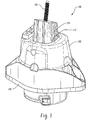
Figure 1 is a perspective view of an assembled hydraulic engine mount or hydromount. -
Figure 2 is an exploded view of various components of the mount assembly ofFigure 1 . -
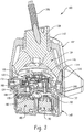
Figure 3 is a longitudinal cross-sectional view of the assembled mount ofFigures 1 and2 . -
Figure 4 is an enlarged view of the lower portion ofFigure 3 . -
Figures 5 and 6 are perspective views of the solenoid assembly used in the switchable engine mount. - Turning first to
Figures 1-3 , there is shown an engine mount orhydromount assembly 100. More particularly, themount assembly 100 includes a restrictor orexternal housing 102 dimensioned to receive a first or elastomeric component ormain rubber element 104 that is generally shaped as a truncated cone, and primarily made of an elastomeric material, such as an elastic rubber as is conventional in the art. A fastener orbolt 106 extends outwardly from themain rubber element 104 for fastening to a power train or engine (not shown) in a manner generally known in the art. Thefastener 106 cooperates with a metal bearing member 108 (Figure 3 ) that has at least a portion encapsulated within the firstelastomeric member 104. In addition, a lower peripheral portion of themain rubber element 104 may include a stiffener, such asmetallic stiffener 110, molded within the main rubber element to add rigidity and support. - The
main rubber element 104 is received within therestrictor housing 102 so that thefastener 106 extends through acentral opening 112 in the restrictor. An internal shoulder 114 (Figure 3 ) of therestrictor 102 abuttingly engages the reinforced, lower portion of themain rubber element 104. In addition, the lower portion of themain rubber element 104 forms a portion of a first orupper fluid chamber 116, namely a high pressure side, of theengine mount 100. The remainder of thefirst fluid chamber 116 is defined by aninertia track assembly 120, more specific details of which will be described below. An outer radial portion of an upper surface of the inertia track assembly denoted byreference numeral 122 abuttingly and sealingly engages themain rubber element 104 in order to seal thefirst fluid chamber 116. As particularly evident inFigure 3 , at least a portion of theinertia track assembly 120 is received within therestrictor housing 102. A second, outer radial portion along the lower surface denoted byreference numeral 124 is sealingly engaged by a rubber boot ordiaphragm 130, and particularly an upperperipheral portion 132 thereof. Thediaphragm 130 includes an opening 134 therethrough for reasons to be described further below. Thediaphragm 130 is protected by adiaphragm cover 140, preferably formed of a more rigid material than the elastomeric diaphragm, and that matingly engages therestrictor housing 102. When thediaphragm cover 140 is fastened to therestrictor 102, the lower peripheral edge of themain rubber element 104 and theperipheral portion 132 of the diaphragm sealingly engage opposite sides orfaces inertia track assembly 120. - As vibrations or displacements are received into the mount from the powertrain, fluid is pumped from the
first fluid chamber 116 through theinertia track assembly 120 in different ways. Particularly, and with continued reference toFigures 1-3 , and additional reference toFigure 4 , theinertia track assembly 120 is disposed between the first orupper fluid chamber 116 and the second orlower fluid chamber 150. Thus, the upper side of theinertia track assembly 120 is associated with the high pressure side of the mount. On the other hand, the lower surface of theinertia track assembly 120 is associated with the second orlower fluid chamber 150 and is sometimes referred to as the low pressure side of the mount. The fluid is pumped from the top to the bottom through theinertia track assembly 120. The fluid response of theinertia track assembly 120 depends on adecoupler 160 and thediaphragm 130. - As noted above, the
diaphragm 130 is sealed about its perimeter to an underside of theinertia track assembly 120, thus forming the second orlower chamber 150 of the engine mount. Fluid between thefirst chamber 116 and thesecond chamber 150 either passes through an elongatedserpentine path 172 or through a more direct, bypass oridle port passage 174. - As shown in
Figures 3 and4 , thepassage 174 is closed by a first or anidle port valve 166. Theidle port valve 160 is normally closed as a result of the biasing force imposed byspring 168 that urges the idle port valve toward a closed position (downwardly as illustrated in the figures). As a result, fluid communicates between the first andsecond chambers serpentine path 172. Fluid is sent through thiselongated path 172 in theinertia track 120 to damp the vibration energy (e.g., non-idle, high amplitude vibrations). - A
first solenoid 180 is mounted so that when the solenoid is energized, a stem/plate 182 is extended (upwardly as shown) and pushes on an underside of thediaphragm 130 which, in turn, pushes upwardly on theidle port valve 166 to overcome the downward biasing force of thespring 168. This energized solenoid action opens theidle port valve 166 and thus thepassage 174 is open to allow communication between thefirst chamber 116 and thesecond chamber 150. Typically, thefirst solenoid 180 is only active during the idle state, and by pushing upwardly on theidle valve 166 to allow fluid flow through theidle port passage 174, a desired idle rate dip is created. When thefirst solenoid 180 is deenergized, thepassage 174 is closed. - A
second solenoid 190 controls flow through a second port orpassage 200, which is also referred to as a decoupler air port. A stem/seal member 192 extends into sealing engagement with thedecoupler air port 200 when thesecond solenoid 190 is energized. By sealing thesecond port 200, air beneath thedecoupler 160 no longer exhausts to ambient or atmosphere. Noticeably, thepassage 200 extends from acavity 202 beneath the decoupler 160 (Figure 4 ), downwardly through the remainder of theinertia track assembly 120 where the passage passes through thecorresponding opening 134 in thediaphragm 130. Asupport member 142 extends upwardly from theprotective cover member 140 and overlies thesecond solenoid 190. Thesupport member 142 includes anopening 144 in an upper portion thereof that is aligned with theopening 134 in thediaphragm 130, and also receives a portion of thedecoupler air port 200. Thesupport member 142, and particularly the alignedopenings decoupler airport passage 200 for selective engagement with theseal member 192 of thesecond solenoid 190. When energized, thesecond solenoid 190 urges theseal member 192 to seal thedecoupler air port 200, thereby trapping air incavity 202 beneath thedecoupler 160. This stops movement of thedecoupler 160. Preferably, thesecond solenoid 190 is also active in the idle state. - As is also evident in the Figures, the
first solenoid 180 is larger than thesecond solenoid 190. Thesecond solenoid 190 requires considerably less power than the first oridle solenoid 180 and thus the reason for its reduced, relative size. - Another advantageous feature of the multi-state electrical mount shown and described above is that in the absence of electronic failure, both the first and
second solenoids idle port passage 174 is closed by theidle port valve 166 and thedecoupler air port 200 is open so that thecavity 202 beneath thedecoupler 160 communicates with ambient. This allows the assembly to operate as a decoupled hydromount. - This written description uses examples to describe the disclosure, including the best mode, and also to enable any person skilled in the art to make and use the disclosure. The patentable scope of the disclosure is defined by the claims, and may include other examples that occur to those skilled in the art. Such other examples are intended to be within the scope of the claims if they have structural elements that do not differ from the literal language of the claims, or if they include equivalent structural elements with insubstantial differences from the literal language of the claims. Moreover, this disclosure is intended to seek protection for a combination of components and/or steps and a combination of claims as originally presented for examination, as well as seek potential protection for other combinations of components and/or steps and combinations of claims during prosecution.
Claims (15)
- A multistate electronically switchable engine mount assembly (100) comprising:a housing;an inertia track (120) received in the housing and having an elongated fluid damped first path (172) that is adapted to communicate with an associated first fluid chamber (116) on a first side and an associated second fluid chamber (150) on a second side, and a non-damped second path that is adapted to communicate with the associated first and second fluid chambers (116, 150);a decoupler (160);an idle diaphragm (130) in the housing that selectively controls communication between the first and second fluid chambers (116, 150) to selectively alter the damping;first idle (174) and second decoupler (200) ports in the housing that communicate with the idle diaphragm (130) and the decoupler (160), respectively;a first solenoid (180) that selectively controls fluid flow through the first idle port (174); anda second solenoid (190) that selectively controls fluid flow through the second decoupler port (200),characterised in that the first solenoid (180) is larger than the second solenoid (190).
- The assembly (100) of claim 1 wherein in the absence of electrical power, the assembly operates as a decoupled hydromount.
- The assembly (100) of claim 2 wherein the first idle port (174) is normally closed and the second decoupler port (200) is normally open.
- The assembly (100) of claim 2 wherein the first idle port (174) is an idle fluid port (174).
- The assembly (100) of claim 4 wherein the second decoupler port (200) is a decoupler air port (200).
- The assembly (100) of claim 1 wherein the idle diaphragm (130) includes a first opening (134) therethrough.
- The assembly (100) of claim 6 wherein the first opening (134) is aligned with the second solenoid (190).
- The assembly (100) of claim 7 wherein the inertia track (120) includes an elongated air port member extending through the first opening (134) in the idle diaphragm (130) that communicates with the decoupler (160).
- The assembly (100) of claim 8 further comprising a diaphragm cover (140) interposed between the idle diaphragm (130) and the first and second solenoids (180, 190).
- The assembly (100) of claim 9 wherein the diaphragm cover (140) includes a support member (142) that receives a terminal end of the elongated air port member for aligning the terminal end with the second solenoid (190).
- The assembly (100) of claim 1 further comprising a moveable valve (166) that controls flow through the first idle port (174) in the inertia track (120).
- The assembly (100) of claim 11 further comprising a biasing spring (168) urging the valve (166) to a normally closed position with the first idle port (174).
- A method of making an engine mount comprising:providing a housing;positioning an inertia track (120) in the housing that has an elongated fluid damped first path (172) that is adapted to communicate with an associated first fluid chamber (116) on a first side and an associated second fluid chamber (150) on a second side, and a non-damped second path that is adapted to communicate with the associated first and second fluid chambers (116, 150);providing a decoupler (160) in the housing to selectively close at least one of the first (172) and second paths;supplying a diaphragm (130) in the housing to selectively control communication between the first and second fluid chambers (116, 150) and to selectively alter the damping state;providing first (174) and second (200) ports in the housing to communicate with the idle diaphragm (130) and the decoupler (160), respectively; andproviding first (180) and second (190) solenoids that control fluid flow through the first (174) and second (200) ports, respectively,characterised in that the method includes making the first solenoid (180) larger than the second solenoid (190).
- The method of claim 13 wherein providing the first port (174) includes providing an idle fluid port that is normally closed.
- The method of claim 14 wherein providing the second port (200) includes providing a decoupler air port that is normally open.
Applications Claiming Priority (2)
| Application Number | Priority Date | Filing Date | Title |
|---|---|---|---|
| US201461923020P | 2014-01-02 | 2014-01-02 | |
| PCT/US2014/073026 WO2015103406A1 (en) | 2014-01-02 | 2014-12-31 | Multi-state electronically switchable engine mount assembly |
Publications (3)
| Publication Number | Publication Date |
|---|---|
| EP3094882A1 EP3094882A1 (en) | 2016-11-23 |
| EP3094882A4 EP3094882A4 (en) | 2017-11-08 |
| EP3094882B1 true EP3094882B1 (en) | 2019-10-23 |
Family
ID=53494021
Family Applications (1)
| Application Number | Title | Priority Date | Filing Date |
|---|---|---|---|
| EP14876084.6A Active EP3094882B1 (en) | 2014-01-02 | 2014-12-31 | Multi-state electronically switchable engine mount assembly |
Country Status (7)
| Country | Link |
|---|---|
| US (1) | US9581218B2 (en) |
| EP (1) | EP3094882B1 (en) |
| JP (1) | JP6596004B2 (en) |
| CN (1) | CN106536968B (en) |
| CA (1) | CA2943567A1 (en) |
| MX (1) | MX2016008826A (en) |
| WO (1) | WO2015103406A1 (en) |
Families Citing this family (3)
| Publication number | Priority date | Publication date | Assignee | Title |
|---|---|---|---|---|
| US10167923B2 (en) * | 2016-07-18 | 2019-01-01 | GM Global Technology Operations LLC | Hydraulic powertrain mount with dual low frequency inertia tracks and decoupling membrane with synchronous switching mechanization |
| KR101849651B1 (en) * | 2016-08-26 | 2018-04-23 | (주)디티알 | Hydraulic engine mount with two channels |
| US11674397B2 (en) * | 2020-11-18 | 2023-06-13 | General Electric Company | Variable stiffness damper system |
Family Cites Families (20)
| Publication number | Priority date | Publication date | Assignee | Title |
|---|---|---|---|---|
| JPS6317347U (en) * | 1986-07-18 | 1988-02-04 | ||
| JPS646543A (en) * | 1987-06-29 | 1989-01-11 | Bridgestone Corp | Vibration isolating device |
| US4783062A (en) | 1987-07-01 | 1988-11-08 | General Motors Corporation | Electronic hydraulic mount-internal solenoid |
| JP3038138B2 (en) * | 1995-07-07 | 2000-05-08 | 東海ゴム工業株式会社 | Fluid-filled engine mount |
| US5620168A (en) * | 1996-01-02 | 1997-04-15 | Tokai Rubber Industries, Ltd. | Fluid-filled elastic mount having orifice passage control rotary valve connected to drive rod at radial position offset from rotation axis of the valve |
| FR2782764B1 (en) * | 1998-08-31 | 2000-11-10 | Hutchinson | ACTIVE HYDRAULIC ANTI-VIBRATION SUPPORT WITH PNEUMATIC CONTROL |
| US20040070125A1 (en) * | 1999-03-18 | 2004-04-15 | Osamu Nakagaki | Liquid-sealed vibration-proof device |
| US6361031B1 (en) | 2000-02-25 | 2002-03-26 | Delphi Technologies, Inc. | Adaptive hydraulic engine mount |
| US6722641B2 (en) * | 2000-09-19 | 2004-04-20 | Toyo Tire & Rubber Co., Ltd. | Liquid filled type vibration isolator |
| JP2002174288A (en) * | 2000-12-05 | 2002-06-21 | Tokai Rubber Ind Ltd | Pneumatic active vibration isolator |
| JP3715230B2 (en) * | 2001-10-29 | 2005-11-09 | 東海ゴム工業株式会社 | Active fluid filled vibration isolator |
| JP2003148550A (en) * | 2001-11-12 | 2003-05-21 | Bridgestone Corp | Damping device |
| US20040150145A1 (en) * | 2003-01-31 | 2004-08-05 | Delphi Technologies Inc. | Bi-state rate dip hydraulic mount |
| FR2872878B1 (en) * | 2004-07-07 | 2008-07-04 | Hutchinson Sa | PILOTABLE HYDRAULIC ANTIVIBRATORY SUPPORT |
| JP4273499B2 (en) * | 2004-07-23 | 2009-06-03 | Smc株式会社 | solenoid valve |
| KR101587863B1 (en) * | 2008-02-21 | 2016-01-22 | 쿠퍼-스탠다드 오토모티브 인코포레이티드 | Multi-stage switchable inertia track assembly |
| CN100588853C (en) * | 2008-05-07 | 2010-02-10 | 浙江骆氏减震件股份有限公司 | Engine variable damping suspension vibration reduction device |
| US9074653B2 (en) * | 2008-10-21 | 2015-07-07 | GM Global Technology Operations LLC | Multistate switchable engine mount and system |
| JP2011038595A (en) * | 2009-08-11 | 2011-02-24 | Bridgestone Corp | Vibration isolating device |
| KR101288997B1 (en) * | 2011-07-01 | 2013-07-23 | 주식회사 대흥알앤티 | Switching engine mount apparatus |
-
2014
- 2014-12-31 CN CN201480076287.4A patent/CN106536968B/en active Active
- 2014-12-31 EP EP14876084.6A patent/EP3094882B1/en active Active
- 2014-12-31 WO PCT/US2014/073026 patent/WO2015103406A1/en not_active Ceased
- 2014-12-31 JP JP2016544618A patent/JP6596004B2/en not_active Expired - Fee Related
- 2014-12-31 CA CA2943567A patent/CA2943567A1/en not_active Abandoned
- 2014-12-31 MX MX2016008826A patent/MX2016008826A/en unknown
- 2014-12-31 US US14/587,884 patent/US9581218B2/en active Active
Non-Patent Citations (1)
| Title |
|---|
| None * |
Also Published As
| Publication number | Publication date |
|---|---|
| CN106536968A (en) | 2017-03-22 |
| US20150377317A1 (en) | 2015-12-31 |
| EP3094882A1 (en) | 2016-11-23 |
| WO2015103406A1 (en) | 2015-07-09 |
| JP2017508111A (en) | 2017-03-23 |
| CN106536968B (en) | 2019-11-05 |
| US9581218B2 (en) | 2017-02-28 |
| CA2943567A1 (en) | 2015-07-09 |
| JP6596004B2 (en) | 2019-10-23 |
| EP3094882A4 (en) | 2017-11-08 |
| MX2016008826A (en) | 2017-10-23 |
Similar Documents
| Publication | Publication Date | Title |
|---|---|---|
| CA2716344C (en) | Multi-stage switchable inertia track assembly | |
| US20120049424A1 (en) | Electronically switchable bi-state engine mount | |
| EP1185800B1 (en) | Adaptive hydraulic engine mount | |
| KR101288997B1 (en) | Switching engine mount apparatus | |
| US9895965B2 (en) | Passively controlled dual-state vacuum switchable mount | |
| US9416843B2 (en) | Hydraulic vibration-damping support | |
| GB2505759A (en) | A hydraulically damped mounting device | |
| US7052003B2 (en) | Vibration isolating apparatus | |
| US9581218B2 (en) | Multi-state electronically switchable engine mount assembly | |
| JP2006258184A (en) | Fluid filled vibration isolator | |
| KR100952776B1 (en) | Engine mount unit | |
| JP2008232340A (en) | Liquid filled vibration isolator | |
| JP4210851B2 (en) | Fluid-filled engine mount for vehicles | |
| KR102440671B1 (en) | Semi active engine mount for vehicle | |
| JPH09222148A (en) | Liquid sealing type mount | |
| JP5060971B2 (en) | Fluid-filled vibration isolator and its operation control method | |
| CA2713695C (en) | Multi-stage switchable inertia track assembly | |
| US20070102855A1 (en) | Switchable hydrobushing | |
| JP2007263301A (en) | Fluid filled vibration isolator |
Legal Events
| Date | Code | Title | Description |
|---|---|---|---|
| PUAI | Public reference made under article 153(3) epc to a published international application that has entered the european phase |
Free format text: ORIGINAL CODE: 0009012 |
|
| 17P | Request for examination filed |
Effective date: 20160720 |
|
| AK | Designated contracting states |
Kind code of ref document: A1 Designated state(s): AL AT BE BG CH CY CZ DE DK EE ES FI FR GB GR HR HU IE IS IT LI LT LU LV MC MK MT NL NO PL PT RO RS SE SI SK SM TR |
|
| AX | Request for extension of the european patent |
Extension state: BA ME |
|
| DAX | Request for extension of the european patent (deleted) | ||
| A4 | Supplementary search report drawn up and despatched |
Effective date: 20171009 |
|
| RIC1 | Information provided on ipc code assigned before grant |
Ipc: F16F 13/26 20060101AFI20171003BHEP |
|
| STAA | Information on the status of an ep patent application or granted ep patent |
Free format text: STATUS: REQUEST FOR EXAMINATION WAS MADE |
|
| GRAP | Despatch of communication of intention to grant a patent |
Free format text: ORIGINAL CODE: EPIDOSNIGR1 |
|
| STAA | Information on the status of an ep patent application or granted ep patent |
Free format text: STATUS: GRANT OF PATENT IS INTENDED |
|
| RAP1 | Party data changed (applicant data changed or rights of an application transferred) |
Owner name: MCDONOUGH, WILLIAM, B. Owner name: COOPER-STANDARD AUTOMOTIVE INC. Owner name: BRADSHAW, JEFF |
|
| INTG | Intention to grant announced |
Effective date: 20190507 |
|
| GRAS | Grant fee paid |
Free format text: ORIGINAL CODE: EPIDOSNIGR3 |
|
| GRAA | (expected) grant |
Free format text: ORIGINAL CODE: 0009210 |
|
| STAA | Information on the status of an ep patent application or granted ep patent |
Free format text: STATUS: THE PATENT HAS BEEN GRANTED |
|
| AK | Designated contracting states |
Kind code of ref document: B1 Designated state(s): AL AT BE BG CH CY CZ DE DK EE ES FI FR GB GR HR HU IE IS IT LI LT LU LV MC MK MT NL NO PL PT RO RS SE SI SK SM TR |
|
| RAP1 | Party data changed (applicant data changed or rights of an application transferred) |
Owner name: MCDONOUGH, WILLIAM, B. Owner name: BRADSHAW, JEFF Owner name: CONTITECH USA, INC. |
|
| REG | Reference to a national code |
Ref country code: GB Ref legal event code: FG4D |
|
| REG | Reference to a national code |
Ref country code: CH Ref legal event code: EP |
|
| REG | Reference to a national code |
Ref country code: IE Ref legal event code: FG4D |
|
| REG | Reference to a national code |
Ref country code: DE Ref legal event code: R096 Ref document number: 602014055754 Country of ref document: DE |
|
| REG | Reference to a national code |
Ref country code: AT Ref legal event code: REF Ref document number: 1193999 Country of ref document: AT Kind code of ref document: T Effective date: 20191115 |
|
| REG | Reference to a national code |
Ref country code: NL Ref legal event code: MP Effective date: 20191023 |
|
| REG | Reference to a national code |
Ref country code: LT Ref legal event code: MG4D |
|
| PG25 | Lapsed in a contracting state [announced via postgrant information from national office to epo] |
Ref country code: PT Free format text: LAPSE BECAUSE OF FAILURE TO SUBMIT A TRANSLATION OF THE DESCRIPTION OR TO PAY THE FEE WITHIN THE PRESCRIBED TIME-LIMIT Effective date: 20200224 Ref country code: FI Free format text: LAPSE BECAUSE OF FAILURE TO SUBMIT A TRANSLATION OF THE DESCRIPTION OR TO PAY THE FEE WITHIN THE PRESCRIBED TIME-LIMIT Effective date: 20191023 Ref country code: BG Free format text: LAPSE BECAUSE OF FAILURE TO SUBMIT A TRANSLATION OF THE DESCRIPTION OR TO PAY THE FEE WITHIN THE PRESCRIBED TIME-LIMIT Effective date: 20200123 Ref country code: NL Free format text: LAPSE BECAUSE OF FAILURE TO SUBMIT A TRANSLATION OF THE DESCRIPTION OR TO PAY THE FEE WITHIN THE PRESCRIBED TIME-LIMIT Effective date: 20191023 Ref country code: SE Free format text: LAPSE BECAUSE OF FAILURE TO SUBMIT A TRANSLATION OF THE DESCRIPTION OR TO PAY THE FEE WITHIN THE PRESCRIBED TIME-LIMIT Effective date: 20191023 Ref country code: LV Free format text: LAPSE BECAUSE OF FAILURE TO SUBMIT A TRANSLATION OF THE DESCRIPTION OR TO PAY THE FEE WITHIN THE PRESCRIBED TIME-LIMIT Effective date: 20191023 Ref country code: GR Free format text: LAPSE BECAUSE OF FAILURE TO SUBMIT A TRANSLATION OF THE DESCRIPTION OR TO PAY THE FEE WITHIN THE PRESCRIBED TIME-LIMIT Effective date: 20200124 Ref country code: PL Free format text: LAPSE BECAUSE OF FAILURE TO SUBMIT A TRANSLATION OF THE DESCRIPTION OR TO PAY THE FEE WITHIN THE PRESCRIBED TIME-LIMIT Effective date: 20191023 Ref country code: LT Free format text: LAPSE BECAUSE OF FAILURE TO SUBMIT A TRANSLATION OF THE DESCRIPTION OR TO PAY THE FEE WITHIN THE PRESCRIBED TIME-LIMIT Effective date: 20191023 Ref country code: NO Free format text: LAPSE BECAUSE OF FAILURE TO SUBMIT A TRANSLATION OF THE DESCRIPTION OR TO PAY THE FEE WITHIN THE PRESCRIBED TIME-LIMIT Effective date: 20200123 |
|
| PG25 | Lapsed in a contracting state [announced via postgrant information from national office to epo] |
Ref country code: HR Free format text: LAPSE BECAUSE OF FAILURE TO SUBMIT A TRANSLATION OF THE DESCRIPTION OR TO PAY THE FEE WITHIN THE PRESCRIBED TIME-LIMIT Effective date: 20191023 Ref country code: IS Free format text: LAPSE BECAUSE OF FAILURE TO SUBMIT A TRANSLATION OF THE DESCRIPTION OR TO PAY THE FEE WITHIN THE PRESCRIBED TIME-LIMIT Effective date: 20200224 Ref country code: RS Free format text: LAPSE BECAUSE OF FAILURE TO SUBMIT A TRANSLATION OF THE DESCRIPTION OR TO PAY THE FEE WITHIN THE PRESCRIBED TIME-LIMIT Effective date: 20191023 |
|
| PG25 | Lapsed in a contracting state [announced via postgrant information from national office to epo] |
Ref country code: AL Free format text: LAPSE BECAUSE OF FAILURE TO SUBMIT A TRANSLATION OF THE DESCRIPTION OR TO PAY THE FEE WITHIN THE PRESCRIBED TIME-LIMIT Effective date: 20191023 |
|
| REG | Reference to a national code |
Ref country code: DE Ref legal event code: R097 Ref document number: 602014055754 Country of ref document: DE |
|
| PG2D | Information on lapse in contracting state deleted |
Ref country code: IS |
|
| PG25 | Lapsed in a contracting state [announced via postgrant information from national office to epo] |
Ref country code: DK Free format text: LAPSE BECAUSE OF FAILURE TO SUBMIT A TRANSLATION OF THE DESCRIPTION OR TO PAY THE FEE WITHIN THE PRESCRIBED TIME-LIMIT Effective date: 20191023 Ref country code: EE Free format text: LAPSE BECAUSE OF FAILURE TO SUBMIT A TRANSLATION OF THE DESCRIPTION OR TO PAY THE FEE WITHIN THE PRESCRIBED TIME-LIMIT Effective date: 20191023 Ref country code: ES Free format text: LAPSE BECAUSE OF FAILURE TO SUBMIT A TRANSLATION OF THE DESCRIPTION OR TO PAY THE FEE WITHIN THE PRESCRIBED TIME-LIMIT Effective date: 20191023 Ref country code: CZ Free format text: LAPSE BECAUSE OF FAILURE TO SUBMIT A TRANSLATION OF THE DESCRIPTION OR TO PAY THE FEE WITHIN THE PRESCRIBED TIME-LIMIT Effective date: 20191023 Ref country code: RO Free format text: LAPSE BECAUSE OF FAILURE TO SUBMIT A TRANSLATION OF THE DESCRIPTION OR TO PAY THE FEE WITHIN THE PRESCRIBED TIME-LIMIT Effective date: 20191023 Ref country code: IS Free format text: LAPSE BECAUSE OF FAILURE TO SUBMIT A TRANSLATION OF THE DESCRIPTION OR TO PAY THE FEE WITHIN THE PRESCRIBED TIME-LIMIT Effective date: 20200223 |
|
| REG | Reference to a national code |
Ref country code: CH Ref legal event code: PL |
|
| REG | Reference to a national code |
Ref country code: AT Ref legal event code: MK05 Ref document number: 1193999 Country of ref document: AT Kind code of ref document: T Effective date: 20191023 |
|
| REG | Reference to a national code |
Ref country code: BE Ref legal event code: MM Effective date: 20191231 |
|
| PLBE | No opposition filed within time limit |
Free format text: ORIGINAL CODE: 0009261 |
|
| STAA | Information on the status of an ep patent application or granted ep patent |
Free format text: STATUS: NO OPPOSITION FILED WITHIN TIME LIMIT |
|
| PG25 | Lapsed in a contracting state [announced via postgrant information from national office to epo] |
Ref country code: MC Free format text: LAPSE BECAUSE OF FAILURE TO SUBMIT A TRANSLATION OF THE DESCRIPTION OR TO PAY THE FEE WITHIN THE PRESCRIBED TIME-LIMIT Effective date: 20191023 Ref country code: IT Free format text: LAPSE BECAUSE OF FAILURE TO SUBMIT A TRANSLATION OF THE DESCRIPTION OR TO PAY THE FEE WITHIN THE PRESCRIBED TIME-LIMIT Effective date: 20191023 Ref country code: SK Free format text: LAPSE BECAUSE OF FAILURE TO SUBMIT A TRANSLATION OF THE DESCRIPTION OR TO PAY THE FEE WITHIN THE PRESCRIBED TIME-LIMIT Effective date: 20191023 Ref country code: SM Free format text: LAPSE BECAUSE OF FAILURE TO SUBMIT A TRANSLATION OF THE DESCRIPTION OR TO PAY THE FEE WITHIN THE PRESCRIBED TIME-LIMIT Effective date: 20191023 |
|
| GBPC | Gb: european patent ceased through non-payment of renewal fee |
Effective date: 20200123 |
|
| 26N | No opposition filed |
Effective date: 20200724 |
|
| PG25 | Lapsed in a contracting state [announced via postgrant information from national office to epo] |
Ref country code: LU Free format text: LAPSE BECAUSE OF NON-PAYMENT OF DUE FEES Effective date: 20191231 Ref country code: IE Free format text: LAPSE BECAUSE OF NON-PAYMENT OF DUE FEES Effective date: 20191231 Ref country code: GB Free format text: LAPSE BECAUSE OF NON-PAYMENT OF DUE FEES Effective date: 20200123 |
|
| PLAA | Information modified related to event that no opposition was filed |
Free format text: ORIGINAL CODE: 0009299DELT |
|
| PLBE | No opposition filed within time limit |
Free format text: ORIGINAL CODE: 0009261 |
|
| PG25 | Lapsed in a contracting state [announced via postgrant information from national office to epo] |
Ref country code: AT Free format text: LAPSE BECAUSE OF FAILURE TO SUBMIT A TRANSLATION OF THE DESCRIPTION OR TO PAY THE FEE WITHIN THE PRESCRIBED TIME-LIMIT Effective date: 20191023 Ref country code: LI Free format text: LAPSE BECAUSE OF NON-PAYMENT OF DUE FEES Effective date: 20191231 Ref country code: CH Free format text: LAPSE BECAUSE OF NON-PAYMENT OF DUE FEES Effective date: 20191231 Ref country code: SI Free format text: LAPSE BECAUSE OF FAILURE TO SUBMIT A TRANSLATION OF THE DESCRIPTION OR TO PAY THE FEE WITHIN THE PRESCRIBED TIME-LIMIT Effective date: 20191023 Ref country code: BE Free format text: LAPSE BECAUSE OF NON-PAYMENT OF DUE FEES Effective date: 20191231 |
|
| R26N | No opposition filed (corrected) |
Effective date: 20200724 |
|
| RAP2 | Party data changed (patent owner data changed or rights of a patent transferred) |
Owner name: CONTITECH VIBRATION CONTROL GMBH Owner name: MCDONOUGH, WILLIAM, B. Owner name: BRADSHAW, JEFF |
|
| REG | Reference to a national code |
Ref country code: DE Ref legal event code: R082 Ref document number: 602014055754 Country of ref document: DE Representative=s name: PREUSSER, ANDREA, DIPL.-MIN. DR. RER. NAT., DE Ref country code: DE Ref legal event code: R081 Ref document number: 602014055754 Country of ref document: DE Owner name: BRADSHAW, JEFF, BLOOMFIELD, US Free format text: FORMER OWNERS: BRADSHAW, JEFF, BLOOMFIELD, MI, US; CONTITECH USA, INC., FAIRLAWN, OHIO, US; MCDONOUGH, WILLIAM B., ORTONVILLE, MI, US Ref country code: DE Ref legal event code: R081 Ref document number: 602014055754 Country of ref document: DE Owner name: CONTITECH VIBRATION CONTROL GMBH, DE Free format text: FORMER OWNERS: BRADSHAW, JEFF, BLOOMFIELD, MI, US; CONTITECH USA, INC., FAIRLAWN, OHIO, US; MCDONOUGH, WILLIAM B., ORTONVILLE, MI, US Ref country code: DE Ref legal event code: R081 Ref document number: 602014055754 Country of ref document: DE Owner name: MCDONOUGH, WILLIAM B., ORTONVILLE, US Free format text: FORMER OWNERS: BRADSHAW, JEFF, BLOOMFIELD, MI, US; CONTITECH USA, INC., FAIRLAWN, OHIO, US; MCDONOUGH, WILLIAM B., ORTONVILLE, MI, US |
|
| PG25 | Lapsed in a contracting state [announced via postgrant information from national office to epo] |
Ref country code: CY Free format text: LAPSE BECAUSE OF FAILURE TO SUBMIT A TRANSLATION OF THE DESCRIPTION OR TO PAY THE FEE WITHIN THE PRESCRIBED TIME-LIMIT Effective date: 20191023 |
|
| PG25 | Lapsed in a contracting state [announced via postgrant information from national office to epo] |
Ref country code: MT Free format text: LAPSE BECAUSE OF FAILURE TO SUBMIT A TRANSLATION OF THE DESCRIPTION OR TO PAY THE FEE WITHIN THE PRESCRIBED TIME-LIMIT Effective date: 20191023 Ref country code: HU Free format text: LAPSE BECAUSE OF FAILURE TO SUBMIT A TRANSLATION OF THE DESCRIPTION OR TO PAY THE FEE WITHIN THE PRESCRIBED TIME-LIMIT; INVALID AB INITIO Effective date: 20141231 |
|
| PG25 | Lapsed in a contracting state [announced via postgrant information from national office to epo] |
Ref country code: TR Free format text: LAPSE BECAUSE OF FAILURE TO SUBMIT A TRANSLATION OF THE DESCRIPTION OR TO PAY THE FEE WITHIN THE PRESCRIBED TIME-LIMIT Effective date: 20191023 |
|
| PG25 | Lapsed in a contracting state [announced via postgrant information from national office to epo] |
Ref country code: MK Free format text: LAPSE BECAUSE OF FAILURE TO SUBMIT A TRANSLATION OF THE DESCRIPTION OR TO PAY THE FEE WITHIN THE PRESCRIBED TIME-LIMIT Effective date: 20191023 |
|
| REG | Reference to a national code |
Ref country code: DE Ref legal event code: R081 Ref document number: 602014055754 Country of ref document: DE Owner name: MCDONOUGH, WILLIAM B., ORTONVILLE, US Free format text: FORMER OWNERS: BRADSHAW, JEFF, BLOOMFIELD, MI, US; CONTITECH VIBRATION CONTROL GMBH, 30165 HANNOVER, DE; MCDONOUGH, WILLIAM B., ORTONVILLE, MI, US Ref country code: DE Ref legal event code: R081 Ref document number: 602014055754 Country of ref document: DE Owner name: CONTITECH VIBRATION CONTROL GMBH, DE Free format text: FORMER OWNERS: BRADSHAW, JEFF, BLOOMFIELD, MI, US; CONTITECH VIBRATION CONTROL GMBH, 30165 HANNOVER, DE; MCDONOUGH, WILLIAM B., ORTONVILLE, MI, US Ref country code: DE Ref legal event code: R081 Ref document number: 602014055754 Country of ref document: DE Owner name: BRADSHAW, JEFF, BLOOMFIELD, US Free format text: FORMER OWNERS: BRADSHAW, JEFF, BLOOMFIELD, MI, US; CONTITECH VIBRATION CONTROL GMBH, 30165 HANNOVER, DE; MCDONOUGH, WILLIAM B., ORTONVILLE, MI, US |
|
| PGFP | Annual fee paid to national office [announced via postgrant information from national office to epo] |
Ref country code: FR Payment date: 20251223 Year of fee payment: 12 |
|
| PGFP | Annual fee paid to national office [announced via postgrant information from national office to epo] |
Ref country code: DE Payment date: 20251231 Year of fee payment: 12 |