EP3094420B1 - Détecteur de bonne fonctionnement d'un distributeur - Google Patents
Détecteur de bonne fonctionnement d'un distributeur Download PDFInfo
- Publication number
- EP3094420B1 EP3094420B1 EP15702887.9A EP15702887A EP3094420B1 EP 3094420 B1 EP3094420 B1 EP 3094420B1 EP 15702887 A EP15702887 A EP 15702887A EP 3094420 B1 EP3094420 B1 EP 3094420B1
- Authority
- EP
- European Patent Office
- Prior art keywords
- dispenser
- loaded
- dispense event
- dispense
- electrical characteristic
- Prior art date
- Legal status (The legal status is an assumption and is not a legal conclusion. Google has not performed a legal analysis and makes no representation as to the accuracy of the status listed.)
- Active
Links
- 238000011156 evaluation Methods 0.000 title claims description 55
- 239000000463 material Substances 0.000 claims description 36
- 238000000034 method Methods 0.000 claims description 36
- 238000003860 storage Methods 0.000 description 18
- 238000005259 measurement Methods 0.000 description 17
- 238000004891 communication Methods 0.000 description 12
- 238000010586 diagram Methods 0.000 description 8
- 239000003990 capacitor Substances 0.000 description 6
- 239000007788 liquid Substances 0.000 description 6
- 230000006870 function Effects 0.000 description 4
- 239000000443 aerosol Substances 0.000 description 3
- 239000006260 foam Substances 0.000 description 3
- 238000012544 monitoring process Methods 0.000 description 3
- 230000003287 optical effect Effects 0.000 description 3
- 239000000843 powder Substances 0.000 description 3
- 230000004044 response Effects 0.000 description 3
- 239000000344 soap Substances 0.000 description 3
- MHAJPDPJQMAIIY-UHFFFAOYSA-N Hydrogen peroxide Chemical compound OO MHAJPDPJQMAIIY-UHFFFAOYSA-N 0.000 description 2
- 230000003213 activating effect Effects 0.000 description 2
- 230000000844 anti-bacterial effect Effects 0.000 description 2
- 238000005516 engineering process Methods 0.000 description 2
- 239000011344 liquid material Substances 0.000 description 2
- 238000004519 manufacturing process Methods 0.000 description 2
- 238000012986 modification Methods 0.000 description 2
- 230000004048 modification Effects 0.000 description 2
- 238000012806 monitoring device Methods 0.000 description 2
- 230000008569 process Effects 0.000 description 2
- 238000012545 processing Methods 0.000 description 2
- 238000005070 sampling Methods 0.000 description 2
- 230000002123 temporal effect Effects 0.000 description 2
- 230000009471 action Effects 0.000 description 1
- 230000004075 alteration Effects 0.000 description 1
- 239000007864 aqueous solution Substances 0.000 description 1
- 230000005540 biological transmission Effects 0.000 description 1
- 230000004397 blinking Effects 0.000 description 1
- -1 cleansers Substances 0.000 description 1
- 238000004590 computer program Methods 0.000 description 1
- 239000000645 desinfectant Substances 0.000 description 1
- 230000007613 environmental effect Effects 0.000 description 1
- 230000005669 field effect Effects 0.000 description 1
- 238000001914 filtration Methods 0.000 description 1
- 239000012530 fluid Substances 0.000 description 1
- 239000000499 gel Substances 0.000 description 1
- 239000006210 lotion Substances 0.000 description 1
- 238000005461 lubrication Methods 0.000 description 1
- 238000012423 maintenance Methods 0.000 description 1
- 230000007246 mechanism Effects 0.000 description 1
- 230000002093 peripheral effect Effects 0.000 description 1
- 238000005507 spraying Methods 0.000 description 1
- 230000007723 transport mechanism Effects 0.000 description 1
Images


Classifications
-
- G—PHYSICS
- G07—CHECKING-DEVICES
- G07F—COIN-FREED OR LIKE APPARATUS
- G07F9/00—Details other than those peculiar to special kinds or types of apparatus
- G07F9/001—Interfacing with vending machines using mobile or wearable devices
-
- G—PHYSICS
- G07—CHECKING-DEVICES
- G07F—COIN-FREED OR LIKE APPARATUS
- G07F9/00—Details other than those peculiar to special kinds or types of apparatus
- G07F9/02—Devices for alarm or indication, e.g. when empty; Advertising arrangements in coin-freed apparatus
- G07F9/026—Devices for alarm or indication, e.g. when empty; Advertising arrangements in coin-freed apparatus for alarm, monitoring and auditing in vending machines or means for indication, e.g. when empty
-
- A—HUMAN NECESSITIES
- A47—FURNITURE; DOMESTIC ARTICLES OR APPLIANCES; COFFEE MILLS; SPICE MILLS; SUCTION CLEANERS IN GENERAL
- A47K—SANITARY EQUIPMENT NOT OTHERWISE PROVIDED FOR; TOILET ACCESSORIES
- A47K5/00—Holders or dispensers for soap, toothpaste, or the like
- A47K5/06—Dispensers for soap
- A47K5/12—Dispensers for soap for liquid or pasty soap
- A47K5/1217—Electrical control means for the dispensing mechanism
-
- B—PERFORMING OPERATIONS; TRANSPORTING
- B05—SPRAYING OR ATOMISING IN GENERAL; APPLYING FLUENT MATERIALS TO SURFACES, IN GENERAL
- B05B—SPRAYING APPARATUS; ATOMISING APPARATUS; NOZZLES
- B05B12/00—Arrangements for controlling delivery; Arrangements for controlling the spray area
- B05B12/004—Arrangements for controlling delivery; Arrangements for controlling the spray area comprising sensors for monitoring the delivery, e.g. by displaying the sensed value or generating an alarm
-
- B—PERFORMING OPERATIONS; TRANSPORTING
- B05—SPRAYING OR ATOMISING IN GENERAL; APPLYING FLUENT MATERIALS TO SURFACES, IN GENERAL
- B05B—SPRAYING APPARATUS; ATOMISING APPARATUS; NOZZLES
- B05B12/00—Arrangements for controlling delivery; Arrangements for controlling the spray area
- B05B12/08—Arrangements for controlling delivery; Arrangements for controlling the spray area responsive to condition of liquid or other fluent material to be discharged, of ambient medium or of target ; responsive to condition of spray devices or of supply means, e.g. pipes, pumps or their drive means
- B05B12/081—Arrangements for controlling delivery; Arrangements for controlling the spray area responsive to condition of liquid or other fluent material to be discharged, of ambient medium or of target ; responsive to condition of spray devices or of supply means, e.g. pipes, pumps or their drive means responsive to the weight of a reservoir or container for liquid or other fluent material; responsive to level or volume of liquid or other fluent material in a reservoir or container
Definitions
- This invention is generally directed towards dispensers for dispensing a material, such as a liquid, powder, aerosol, or other types of materials.
- a material such as a liquid, powder, aerosol, or other types of materials.
- this invention is directed to methods and/or systems for evaluating battery life, faults, and/or other operating conditions of a dispenser.
- dispensers to dispense material.
- a dispenser may dispense a liquid material, powder material, aerosol material, and/or other materials (e.g., soap, anti-bacterial gels, cleansers, disinfectants, lotions, etc.).
- Some dispensers utilize a refill container for ease of maintenance, environmental concerns, etc.
- the refill container may, for example, comprise a pump and/or nozzle mechanism that can be used by a dispenser to dispense material from the refill container.
- a dispenser may utilize a power source to perform various tasks, such as a detect user task, a validate refill container task, a dispense task, etc.
- a hands free dispenser may utilize a battery as a power source.
- the hands free dispenser may utilize a solar panel as a power source.
- the ability of a dispenser to dispense a material may be affected by various faults and/or other problems, such as a low or dead battery, a mechanical stall or other mechanical impedance, a clogged pump, etc.
- Document US 4 668 948 A relates to monitoring devices and more particularly to monitoring devices used to detect malfunctioning fluid dispensers.
- Document EP 0 322 981 A2 relates to an apparatus for determining a rate of discharge from a nozzle for spraying aqueous solution of hydrogen peroxide.
- Document JP S60 257870 A relates to a drive circuit of an atomizer.
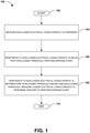
- a non-loaded electrical characteristic of the dispenser is measured (e.g., a non-loaded voltage of a power supply for the dispenser may be measured in response to detecting a request for a dispense event, such as a user activating an actuator sensor of the dispenser). Responsive to the non-loaded electrical characteristic being above a first non-loaded threshold (e.g., a measure voltage of 5.9v that is above a 5.8v first threshold for a 6v dispenser), the dispense event is performed (e.g., a material, such as soap, may be dispensed from a refill container associated with the dispenser).
- a first non-loaded threshold e.g., a measure voltage of 5.9v that is above a 5.8v first threshold for a 6v dispenser
- a loaded electrical characteristic is measured and evaluated against a loaded threshold in order to determine whether to perform or refrain from performing the dispense event.
- a mechanical problem such as a mechanical stall, a gear train problem, an actuator problem, a pump problem, and/or a mechanical impedance, is identified based upon evaluating first peak current during a first timespan of the dispense event.
- a clogged pump is identified based upon evaluating a second peak current during a second timespan of the dispense event.
- battery life is determined based upon a peak current metric and a peak current timespan measured during the dispense event.
- a dry pump e.g., a dispense event when a refill container is empty of material and thus no material is dispensed
- a restrictor and/or a type of the restrictor e.g., a restrictor that adds a gap between an actuator and a pump such that the actuator engages less of the pump in order to reduce an amount of material dispensed by the dispenser
- operability of a transistor e.g., whether one or more transistors used to filter motor current are working or not
- a pump type e.g., a foam pump comprising a chamber, a liquid pump, etc.
- other operating characteristics of the dispenser are identified based upon an evaluation of the dispenser, such as peak current during a dispense event.
- Such operating characteristics, electrical characteristics, and/or metrics are stored as dispense event evaluation data that may be used to subsequently evaluate operation of the dispenser and/or to adjust thresholds used to evaluate the dispenser.
- a service alert of dispense event evaluation data, operational characteristics, electrical characteristics, and/or metrics are provided, such as over a network or a wireless communication channel to a computing device (e.g., for display through a dispenser monitoring application interface or a map, for wireless transmission such as over Bluetooth to a mobile device within a wireless communication range of the dispenser, etc.).
- a dispenser may comprise various components that function to dispense material (e.g., dispense a liquid, such as soap, from a refill container).
- the dispenser may comprise a motor, a gear train, an actuator, a power source, and/or other components (e.g., a pump and/or a dispenser nozzle associated with a refill container).
- Such components may experience faults, such as mechanical impedances, clogged pumps, low batteries, etc. Accordingly, as provided herein, dispenser functionality is evaluated before a dispense event and/or during the dispense event.
- Evaluation of the dispenser may take into account historical dispense event evaluation data and/or temporal information (e.g., a time since last actuation of a dispense event) so that appropriate action may be taken (e.g., perform a dispense event, refrain from performing a dispense event, provide an alert, etc.).
- temporal information e.g., a time since last actuation of a dispense event
- a non-loaded electrical characteristic of the dispenser may be measured. For example, a non-loaded voltage of the power supply may be measured based upon a user attempting to actuate the dispenser to perform a dispense event.
- a first non-loaded threshold e.g., a non-loaded voltage of 5.9v may be above a first non-loaded threshold of 5.8v for a 6v dispenser
- the dispense event may be performed.
- a loaded electrical characteristic for the dispenser may be measured (e.g., a loaded current and/or a loaded voltage across a drivetrain, a motor, a battery or a separate load such as a current sense resistor and/or a transistor). Responsive to the loaded electrical characteristic being above a loaded threshold, performing the dispense event.
- an alert may be provided (e.g., a blinking light, a digital image message, an RF signal, communication over a network, and/or other alerts).
- the non-loaded electrical characteristic and/or the loaded electrical characteristic may be evaluated against prior dispenser event evaluation data for the dispenser to determine dispenser operating data for the dispenser. For example, if the dispenser operating data indicates a mechanical stall or a clogged pump, then the dispense event may be refrained from being performed. In another example, a time since last dispense metric may be identified and/or used to evaluate the non-loaded electrical current characteristic and/or the loaded electric current characteristic.
- the first non-loaded threshold, the second non-loaded threshold, and/or the loaded threshold may be adjusted based upon dispense event evaluation data for the dispenser (e.g., non-loaded electrical characteristics, loaded electrical characteristics, peak current information, and/or other information collected from prior evaluations of the dispenser).
- a threshold may have been initially set to a factory setting. The threshold may be adjusted based upon performance of the dispenser (e.g., a particular dispenser model may utilize a relatively more efficiency battery, gear train, lubrication, etc.).
- Dispenser functionality may be evaluated and/or recorded during the dispense event.
- First peak current is measured during a first timespan of the dispense event (e.g., a peak or average current measurement derived from one or more current measurement samplings during a first .25 seconds of a 1 second dispense event).
- the first peak current is evaluated to identify a mechanical problem associated with the dispenser, such as a mechanical stall, a gear train problem, an actuator problem, a pump problem, and/or a mechanical impedance.
- an alert of the mechanical problem may be provided.
- dispense event evaluation data may be generated based upon the mechanical problem.
- the dispense event evaluation data and/or other information may be evaluated before and/or during a subsequent dispense event in order to determine whether to perform a subsequent dispense event. If the dispense event evaluation data is indicative of more than one issue, then fuzzy logic may be implemented to determine whether to dispense or not (e.g., if a battery has a relatively high charge and a pump clog was detected over a threshold amount of time prior to a current time, then a dispense event may be performed in an attempt to remove the clog).
- fuzzy logic may be implemented to determine whether to dispense or not (e.g., if a battery has a relatively high charge and a pump clog was detected over a threshold amount of time prior to a current time, then a dispense event may be performed in an attempt to remove the clog).
- a second peak current may be measured during a second timespan of the dispense event (e.g., a peak or average current measurement derived from one or more current measurement samplings during a final .75 seconds of a 1 second dispense event).
- the second peak current may be evaluated to identify a pump problem associated with the dispenser, such as a clogged pump.
- an alert of the pump problem may be provided.
- dispense event evaluation data may be generated based upon the pump problem.
- the dispense event evaluation data and/or other information e.g., a time span since a prior dispense event) may be evaluated before and/or during a subsequent dispense event in order to determine whether to perform a subsequent dispense event.
- a peak current metric and/or a peak current timespan metric may be measured to generate current characteristic data for the dispense event (e.g., Figs. 7 and 8 ).
- a battery status for the dispense event may be determined based upon the current characteristic data (e.g., a relatively lower peak current and/or a relatively longer peak current timespan may be indicative of a relatively lower battery charge).
- dispense event evaluation data may be generated and/or an alert may be provided based upon the battery status. For example, the dispense event evaluation data may be evaluated to determine whether a subsequent dispense event is to be performed or not.
- the method ends.
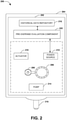
- Fig. 2 illustrates an example of a system 200 for evaluating dispenser functionality of a dispenser 204 for dispensing a material.
- the dispenser 204 may comprise a housing 202 configured to hold a refill container comprising a material (e.g., a liquid material, a powder material, an aerosol material, an antibacterial product, etc.).
- the housing 202 may comprise various mechanical and/or electrical components that facilitate operation of the dispenser 204, such as one or more components that dispense material from the refill container.
- the housing 202 may comprise an actuator 210, a power source 212, a motor 206, a drivetrain 208 (e.g., a gear train), and/or other components (e.g., a pump 214 and/or a dispenser nozzle 216 associated with the refill container).
- the power source 212 e.g., a battery, an AC adapter, power from a powered network communication line, etc.
- the actuator 210 may be configured to detect a dispense request (e.g., a user may place a hand in front of an actuation sensor; the user may press an actuation button or lever; etc.).
- the actuator 210 may be configured to invoke the motor 206 to operate the drivetrain 208 so that the pump 214 dispenses material from the refill container 202 through the dispenser nozzle 216.
- the system 200 may comprise a pre-dispense evaluation component 220 and/or a historical data repository 218.
- the pre-dispense evaluation component 220 may be configured to evaluate the dispenser 204, such as the power source 212, before a dispense event.
- the pre-dispense evaluation component 220 may be configured to measure a non-loaded electrical characteristic of the dispenser 204, such as a non-loaded voltage of the power source 212.
- the pre-dispense evaluation component 220 may evaluate the non-loaded electrical characteristic based upon dispense event evaluation data stored within the historical data repository 218 (e.g., a time since last dispense, a prior measured voltage, a prior measured peak current, a prior alert, a prior measured battery level, etc.).
- the pre-dispense evaluation component 220 may store the non-loaded electrical characteristic into the historical data repository 218 for subsequent evaluations of the dispenser 204. Responsive to the non-loaded electrical characteristic being above a first non-loaded threshold, a dispense event may be performed (e.g., in response to a dispense request detected by the actuator 210). Responsive to the non-loaded electrical characteristic being between the first non-loaded threshold and a second non-loaded threshold, further evaluation of the dispenser 204 may be performed (e.g., Fig. 3 ).
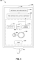
- Fig. 3 illustrates an example of a system 300 for evaluating dispenser functionality of a dispenser 204 for dispensing a material.
- the system 300 may comprise a pre-dispense evaluation component 220.
- the pre-dispense evaluation component 220 may be configured to measure a loaded electrical characteristic of the dispenser 204.
- the pre-dispense evaluation component 220 may measure a loaded voltage across a load 302, such as a current sense resistor.
- the pre-dispense evaluation component 220 may evaluate the loaded electrical characteristic based upon dispense event evaluation data stored within a historical data repository 218 (e.g., a time since last dispense, a prior measured voltage, a prior measured peak current, a prior alert, a prior measured battery level, etc.).
- the pre-dispense evaluation component 220 may store the loaded electrical characteristic into the historical data repository 218 for subsequent evaluations of the dispenser 204. Responsive to the loaded electrical characteristics being above a loaded threshold, a dispense event may be performed (e.g., in response to a dispense request detected by an actuator 210). Responsive to the loaded electrical characteristic being below the loaded threshold, the dispense event may be refrained from being performed.
- Fig. 4 illustrates an example of a system 400 for maintaining one or more thresholds used to evaluate a dispenser 204.
- the system 400 may comprise a pre-dispense evaluation component 220.
- the pre-dispense evaluation component 220 may be configured to evaluate various aspects of the dispenser 204 utilizing a first non-loaded threshold (e.g., such as about 5.8v for a 6v dispenser), a second non-loaded threshold (e.g., such as about 4.9v for the 6v dispenser), a loaded threshold (e.g., such as about 4.2v for the 6v dispenser), a peak current metric, a peak current timespan, and/or other thresholds.
- a first non-loaded threshold e.g., such as about 5.8v for a 6v dispenser
- a second non-loaded threshold e.g., such as about 4.9v for the 6v dispenser
- a loaded threshold e.g., such as about 4.2v for the 6v dispenser
- peak current metric e.g.,
- the pre-dispense evaluation component 220 may be configured to adjust a threshold based upon dispense event evaluation data within a historical data repository 218.
- the loaded threshold may be factory set as 4.2v.
- the dispense event evaluation data may indicate that the dispenser 204 has operated normally at voltages below 4.2v, such as 3.9v, due to the dispenser 204 being relatively efficient (e.g., a drivetrain 208 may have been recently upgraded to a relatively more efficient model). Accordingly, the pre-dispense evaluation component 220 may be configured to adjust 402 the loaded threshold for future evaluations of the dispenser 204.
- An embodiment of evaluating dispenser functionality of a dispenser for dispensing material is illustrated by an exemplary method 500 of Fig. 5 .
- the method starts.
- a first peak current is measured during a first timespan of a dispense event.
- the first peak current is evaluated to identify a mechanical problem associated with the dispenser, such as a mechanical stall, a gear train problem, an actuator problem, a pump problem, and/or a mechanical impedance.
- the first peak current may be evaluated to determine that a current, measured within the dispenser, reached a relatively higher peak value than expected (e.g., a current above a range of 1-4 amps), which may be indicative of the mechanical problem.
- an alert of the mechanical problem may be provided.
- a second peak current may be measured during a second timespan of the dispense event.
- the second peak current may be evaluated to identify a pump problem, such as a clogged pump.
- the second peak current may be evaluated to determine that a current, measured within the dispenser, reached a relatively higher peak value than expected and/or maintained the relatively higher peak value for a relatively longer duration than expected, which may be indicative of a clogged pump.
- an alert of the pump problem may be provided.
- the method ends.
- Fig. 6 illustrates an example of a system 600 for evaluating a dispenser 204 during a dispense event.
- the dispenser 204 initiates the dispense event based upon a user activating an actuator 210 with a hand 604.
- a power source 212 may supply power to a motor 206 that drives a drivetrain 208 so that a pump 214 dispenses a material 602 through a dispenser nozzle 216 into the hand 604 of the user.
- the system 600 may comprise a dispense evaluation component 606 and/or a historical data repository 218.
- the dispense evaluation component 606 may be configured to obtain current measurements 608 during various portions of the dispense event, such as during a first timespan (e.g., a first quarter of the dispense event), a second timespan (e.g., a last three fourths of the dispense event), etc.
- the current measurements 608 may be evaluated against various peak current thresholds and/or expected current curves (e.g., Figs. 7 and 8 ) to determine whether a problem exists, such as a pump problem of the pump 214, a mechanical stall of the motor 206, a drivetrain problem of the drivetrain 208, an actuator problem of the actuator 210, a mechanical impedance, and/or other issues.
- the dispense evaluation component 606 may be configured to evaluate the current measurements 608 against dispense event evaluation data within the historical data repository 218 (e.g., evaluate prior current measurements and/or a time since last dispense to determine whether a problem is a single occurrence or a trending problem, whether to raise an alarm, whether to adjust a threshold, whether to perform or refrain from performing a dispense event, etc.).
- the dispense evaluation component 606 may store the current measurements 608 within the historical data repository 218 for later evaluation of the dispenser 204.
- Fig. 7A illustrates an example of a graph 700 comprising a time axis 706 and a current axis 708.
- An expected current curve 702 may correspond to current values that may be expected during various portions of a normal dispense event.
- a peak current range may span from point 702a to point 702b.
- a measured current curve 704 may correspond to measured current values during a dispense event.
- a measured peak current range may span from point 704a to point 704b.
- the measured current curve 704 may be evaluated against the expected current curve 702 to identify whether the dispenser is functioning as expected or has a problem.
- a low battery status may be determined based upon the measured current curve 704 have a relatively lower peak current than the expected current curve 702 and/or based upon the measured peak current range between point 704a and point 704b having a relative longer duration than the expected peak current range between point 702a and point 702b.
- a dispenser may be evaluated by comparing the measured current curve 704 against the expected current curve 702.
- Fig. 7B illustrates an example of a graph 750 comprising a time axis 756 and a current axis 758.
- An expected current curve 702 may correspond to current values that may be expected during various portions of a normal dispense event.
- a peak current range may span from point 702a to point 702b.
- a measured current curve 754 may correspond to measured current values during a dispense event.
- a measured peak current range may span from point 754a to point 754b.
- the measured current curve 754 may be evaluated against the expected current curve 702 to identify whether the dispenser is functioning as expected or has a problem.
- a mechanical stall problem (e.g., a stall of a motor) may be determined based upon the measured peak current range between point 754a and point 754b having a relative longer duration than the expected peak current range between point 702a and point 702b.
- a dispenser may be evaluated by comparing the measured current curve 754 against the expected current curve 702.
- an exemplary method 800 of Fig. 8 An embodiment of evaluating dispenser functionality of a dispenser for dispensing material is illustrated by an exemplary method 800 of Fig. 8 .
- the method starts.
- an expected current for a dispense event of the dispenser may be determined based upon a non-loaded voltage of the dispenser.
- the non-loaded battery voltage may be obtained when a motor of the dispenser is off (e.g., when the dispenser is not performing a dispense event).
- the non-loaded voltage may be evaluated based upon a slope-intercept function to determine a peak normal current that the motor should draw during a normal dispense event (e.g., a non-problematic dispense event such as without a clog, a dry pump, a mechanical impedance, a gear train problem etc.).
- the slope-intercept function may take into account a motor load, an internal battery resistance, and/or other information for determining the expected current based upon the non-loaded voltage.
- a current measurement of a current dispense event of the dispenser may be obtained.
- the current measurement may comprise a peak current, a current measurement curve, etc.
- the current measurement may be evaluated against the expected current to determine an operational characteristic of the dispenser.
- the operational characteristic may indicate that a dry pump of no material was performed because less current was used for the dry pump than if the dispenser had to pump out material that would have utilized more current.
- the dry pump may indicate that a refill container of the dispenser is empty because the dispenser did not dispense material.
- the operational characteristic may indicate a type of pump utilized by the dispenser, such as a liquid pump, a foam pump, etc.
- a dispenser with a foam pump comprising a chamber such as an air chamber and/or a liquid chamber, may draw more current (e.g., additional current may be drawn to perform work by the chamber) than a liquid pump without such a chamber.
- the operational characteristic may indicate whether the dispenser utilizes a restrictor for an actuator of the dispenser. If the dispenser does not comprise a restrictor, then the actuator may be positioned such that the actuator may immediate engage with a pump during actuation and thus the current measurement curve may have an initial increase in current corresponding to the start of the actuation because the actuator may immediately engage with the pump resulting in a draw of current.
- the restrictor may be positioned such that the restrictor does not immediately engage with the pump during actuation (e.g., dead space, such as an inch or any other amount of dead space, may exist between the restrictor and the pump such that a user pushing against the actuator does not immediate push the restrictor against the pump and thus the dispenser may dispense less material for an actuation) and thus the current measurement curve may have a delay or flat portion with little to no current draw because the initial increase in current occurs once the restrictor finally engages with the pump.
- a type of restrictor may be identified based upon a length of the delay or flat portion of the current measurement curve.
- the operational characteristic may correspond to an operational status (e.g., working, broken, operating out of spec, etc.) of one or more transistors (e.g., a field-effect transistor) within the dispenser.
- the dispenser may comprise a first transistor (e.g., a high side transistor) and a second transistor (e.g., a low side transistor) that are in series with the motor.
- a capacitor may be located at a junction between the first transistor and the second transistor (e.g., the capacitor may be in parallel with one of the transistors and may be shunted to ground). The capacitor may be used for filtering motor current.
- the first transistor e.g., the high side transistor
- the second transistor e.g., the low side transistor
- the first transistor e.g., the high side transistor
- the second transistor e.g., the low side transistor
- the first transistor e.g., the high side transistor
- a service alert may be created based upon the operational characteristic.
- the service alert may be sent over a network to a computing device (e.g., over an Ethernet connection, a WiFi connection, etc.) or may be providing to the computing device utilizing a wireless communication signal (e.g., a Bluetooth connection to a mobile device).
- a computing device e.g., over an Ethernet connection, a WiFi connection, etc.
- a wireless communication signal e.g., a Bluetooth connection to a mobile device.
- the service alert may be displayed through a website (e.g., a dispenser monitoring website), through a map populated with a dispenser user interface element representing the dispenser (e.g., a display property, such as color or size, of the dispenser user interface element may be modified to indicate the service alert; a textual description of the service alert may be provided based upon a user selecting the dispenser user interface element, etc.), and/or an application user interface (e.g., a dispenser monitoring application).
- a website e.g., a dispenser monitoring website
- a map populated with a dispenser user interface element representing the dispenser e.g., a display property, such as color or size, of the dispenser user interface element may be modified to indicate the service alert; a textual description of the service alert may be provided based upon a user selecting the dispenser user interface element, etc.
- an application user interface e.g., a dispenser monitoring application
- Still another embodiment involves a computer-readable medium comprising processor-executable instructions configured to implement one or more of the techniques presented herein.
- An example embodiment of a computer-readable medium or a computer-readable device is illustrated in Fig. 9 , wherein the implementation 900 comprises a computer-readable medium 908, such as a CD-R, DVD-R, flash drive, a platter of a hard disk drive, etc., on which is encoded computer-readable data 906.
- This computer-readable data 906, such as binary data comprising at least one of a zero or a one in turn comprises a set of computer instructions 904 configured to operate according to one or more of the principles set forth herein.
- the processor-executable computer instructions 904 are configured to perform a method 902, such as at least some of the exemplary method 100 of Fig. 1 , at least some of the exemplary method 500 of Fig. 5 , and/or at least some of the exemplary method 800 of Fig. 8 , for example.
- the processor-executable instructions 904 are configured to implement a system, such as at least some of the exemplary system 200 of Fig. 2 , at least some of the exemplary system 300 of Fig. 3 , at least some of the exemplary system 400 of Fig. 4 , at least some of the exemplary system 600 of Fig. 6 , for example.
- Many such computer-readable media are devised by those of ordinary skill in the art that are configured to operate in accordance with the techniques presented herein.
- a component may be, but is not limited to being, a process running on a processor, a processor, an object, an executable, a thread of execution, a program, and/or a computer.
- an application running on a controller and the controller can be a component.
- One or more components may reside within a process and/or thread of execution and a component may be localized on one computer and/or distributed between two or more computers.
- the claimed subject matter may be implemented as a method, apparatus, or article of manufacture using standard programming and/or engineering techniques to produce software, firmware, hardware, or any combination thereof to control a computer to implement the disclosed subject matter.
- article of manufacture as used herein is intended to encompass a computer program accessible from any computer-readable device, carrier, or media.
- Fig. 10 and the following discussion provide a brief, general description of a suitable computing environment to implement embodiments of one or more of the provisions set forth herein.
- the operating environment of Fig. 10 is only one example of a suitable operating environment and is not intended to suggest any limitation as to the scope of use or functionality of the operating environment.
- Example computing devices include, but are not limited to, personal computers, server computers, handheld or laptop devices, mobile devices (such as mobile phones, Personal Digital Assistants (PDAs), media players, and the like), multiprocessor systems, consumer electronics, mini computers, mainframe computers, distributed computing environments that include any of the above systems or devices, and the like.
- Computer readable instructions may be distributed via computer readable media (discussed below).
- Computer readable instructions may be implemented as program modules, such as functions, objects, Application Programming Interfaces (APIs), data structures, and the like, that perform particular tasks or implement particular abstract data types.
- APIs Application Programming Interfaces
- Fig. 10 illustrates an example of a system 1000 comprising a computing device 1012 configured to implement one or more embodiments provided herein.
- computing device 1012 includes at least one processing unit 1016 and memory 1018.
- memory 1018 may be volatile (such as RAM, for example), non-volatile (such as ROM, flash memory, etc., for example) or some combination of the two. This configuration is illustrated in Fig. 10 by dashed line 1014.
- device 1012 may include additional features and/or functionality.
- device 1012 may also include additional storage (e.g., removable and/or non-removable) including, but not limited to, magnetic storage, optical storage, and the like.
- additional storage e.g., removable and/or non-removable
- storage 1020 Such additional storage is illustrated in Fig. 10 by storage 1020.
- computer readable instructions to implement one or more embodiments provided herein may be in storage 1020.
- Storage 1020 may also store other computer readable instructions to implement an operating system, an application program, and the like. Computer readable instructions may be loaded in memory 1018 for execution by processing unit 1016, for example.
- Computer storage media includes volatile and nonvolatile, removable and non-removable media implemented in any method or technology for storage of information such as computer readable instructions or other data.
- Memory 1018 and storage 1020 are examples of computer storage media.
- Computer storage media includes, but is not limited to, RAM, ROM, EEPROM, flash memory or other memory technology, CD-ROM, Digital Versatile Disks (DVDs) or other optical storage, magnetic cassettes, magnetic tape, magnetic disk storage or other magnetic storage devices, or any other medium which can be used to store the desired information and which can be accessed by device 1012. Any such computer storage media may be part of device 1012.
- Device 1012 may also include communication connection(s) 1026 that allows device 1012 to communicate with other devices.
- Communication connection(s) 1026 may include, but is not limited to, a modem, a Network Interface Card (NIC), an integrated network interface, a radio frequency transmitter/receiver, an infrared port, a USB connection, or other interfaces for connecting computing device 1012 to other computing devices.
- Communication connection(s) 1026 may include a wired connection or a wireless connection.
- Communication connection(s) 1026 may transmit and/or receive communication media.
- Computer readable media may include communication media.
- Communication media typically embodies computer readable instructions or other data in a “modulated data signal” such as a carrier wave or other transport mechanism and includes any information delivery media.
- modulated data signal may include a signal that has one or more of its characteristics set or changed in such a manner as to encode information in the signal.
- Device 1012 may include input device(s) 1024 such as keyboard, mouse, pen, voice input device, touch input device, infrared cameras, video input devices, and/or any other input device.
- Output device(s) 1022 such as one or more displays, speakers, printers, and/or any other output device may also be included in device 1012.
- Input device(s) 1024 and output device(s) 1022 may be connected to device 1012 via a wired connection, wireless connection, or any combination thereof.
- an input device or an output device from another computing device may be used as input device(s) 1024 or output device(s) 1022 for computing device 1012.
- Components of computing device 1012 may be connected by various interconnects, such as a bus.
- Such interconnects may include a Peripheral Component Interconnect (PCI), such as PCI Express, a Universal Serial Bus (USB), firewire (IEEE 1394), an optical bus structure, and the like.
- PCI Peripheral Component Interconnect
- USB Universal Serial Bus
- IEEE 1394 Firewire
- optical bus structure and the like.
- components of computing device 1012 may be interconnected by a network.
- memory 1018 may be comprised of multiple physical memory units located in different physical locations interconnected by a network.
- a computing device 1030 accessible via a network 1028 may store computer readable instructions to implement one or more embodiments provided herein.
- Computing device 1012 may access computing device 1030 and download a part or all of the computer readable instructions for execution.
- computing device 1012 may download pieces of the computer readable instructions, as needed, or some instructions may be executed at computing device 1012 and some at computing device 1030.
- one or more of the operations described may constitute computer readable instructions stored on one or more computer readable media, which if executed by a computing device, will cause the computing device to perform the operations described. Further, it will be understood that not all operations are necessarily present in each embodiment provided herein. Also, it will be understood that not all operations are necessary in some embodiments.
- first,” “second,” and/or the like are not intended to imply a temporal aspect, a spatial aspect, an ordering, etc. Rather, such terms are merely used as identifiers, names, etc. for features, elements, items, etc.
- a first object and a second object generally correspond to object A and object B or two different or two identical objects or the same object.
- exemplary is used herein to mean serving as an example, instance, illustration, etc., and not necessarily as advantageous.
- “or” is intended to mean an inclusive “or” rather than an exclusive “or”.
- “a” and “an” as used in this application are generally be construed to mean “one or more” unless specified otherwise or clear from context to be directed to a singular form.
- at least one of A and B and/or the like generally means A or B or both A and B.
- such terms are intended to be inclusive in a manner similar to the term “comprising”.
Landscapes
- Physics & Mathematics (AREA)
- General Physics & Mathematics (AREA)
- Health & Medical Sciences (AREA)
- Public Health (AREA)
- Chemical & Material Sciences (AREA)
- Analytical Chemistry (AREA)
- Business, Economics & Management (AREA)
- Accounting & Taxation (AREA)
- Control Of Positive-Displacement Pumps (AREA)
- Details Or Accessories Of Spraying Plant Or Apparatus (AREA)
- Application Of Or Painting With Fluid Materials (AREA)
- Spray Control Apparatus (AREA)
Claims (12)
- Procédé (100) d'évaluation du bon fonctionnement d'un distributeur (204) destiné à distribuer une matière, comprenant :la mesure d'une caractéristique électrique non chargée (104) d'un distributeur (204) ;en réaction au fait que la caractéristique électrique non chargée est au-dessus d'un premier seuil non chargé, la réalisation d'un événement de distribution (106) ; eten réaction au fait que la caractéristique électrique non chargée est entre le premier seuil non chargé et un second seuil non chargé :la mesure d'une caractéristique électrique chargée du distributeur (204) ;en réaction au fait que la caractéristique électrique chargée est au-dessus d'un seuil chargé, la réalisation de l'événement de distribution ; eten réaction au fait que la caractéristique électrique chargée est en-dessous du seuil chargé, l'abstention de la réalisation de l'événement de distribution (108),caractérisé en ce que le procédé comprend :
pendant un premier laps de temps de l'événement de distribution :la mesure d'une première crête de courant (504) ; etl'évaluation de la première crête de courant pour identifier un problème mécanique (506) associé au distributeur (204). - Procédé selon la revendication 1, la mesure de la caractéristique électrique chargée comprenant :
la mesure d'au moins un paramètre parmi le courant chargé ou une tension chargée dans une charge de moteur de groupe motopropulseur. - Procédé selon la revendication 1, la mesure de la caractéristique électrique chargée comprenant :
la mesure d'au moins un paramètre parmi un courant chargé ou une tension chargée dans une charge séparée depuis un groupe motopropulseur (208) et un moteur (206) du distributeur (204). - Procédé selon la revendication 1, comprenant :l'identification de données d'évaluation de l'événement de distribution pour le distributeur (204) ;l'évaluation de la caractéristique électrique chargée par rapport aux données d'évaluation de l'événement de distribution pour déterminer les données opérationnelles pour le distributeur (204) ;en réaction au fait que les données opérationnelles du distributeur ne sont pas indicatives d'un problème d'événement de distribution, la réalisation de l'événement de distribution ; eten réaction au fait que les données opérationnelles du distributeur sont indicatives d'un problème d'événement de distribution, l'abstention de la réalisation de l'événement de distribution.
- Procédé selon la revendication 1, le problème mécanique comprenant au moins un problème parmi une panne mécanique, un problème de train d'engrenages, un problème d'actionneur, un problème de pompe, ou une impédance mécanique.
- Procédé selon la revendication 1, comprenant :
la génération, avant l'événement de distribution, de données d'évaluation en se basant sur le problème mécanique. - Procédé selon la revendication 1, comprenant :
pendant un second laps de temps de l'événement de distribution :la mesure d'une seconde crête de courant (508), etl'évaluation de la seconde crête de courant pour identifier un problème de pompe (510) associé au distributeur (204). - Procédé selon la revendication 1, comprenant :la détermination d'un temps écoulé depuis la dernière mesure de distribution ; etl'évaluation de la caractéristique électrique chargée et de la durée depuis la dernière mesure de distribution pour déterminer les données opérationnelles de distribution pour le distributeur (204) ;en réaction au fait que les données opérationnelles de distribution ne sont pas indicatives d'un problème d'événement de distribution, la réalisation de l'événement de distribution ; eten réaction au fait que les données opérationnelles de distribution sont indicatives d'un problème d'événement de distribution, l'abstention de réalisation de l'événement de distribution.
- Procédé selon la revendication 1, comprenant :
pendant l'événement de distribution :la prise d'une mesure de crête de courant et d'une mesure de laps de temps de crête de courant pour générer des données caractéristiques de courant pour l'événement de distribution ;la détermination d'un état de batterie pour l'événement de distribution en se basant sur les données de caractéristiques de courant ; eten réaction au fait que l'état de la batterie est en-dessous d'une mesure de courant de distribution, la génération, avant l'événement de distribution, de données d'évacuation en se basant sur l'état de la batterie. - Procédé selon la revendication 1, comprenant :l'identification de données d'évaluation de l'événement de distribution pour le distributeur (204) ; etle réglage d'au moins un seuil parmi le premier seuil non chargé, le second seuil non chargé, ou le seuil chargé en se basant sur les données d'évaluation de l'événement de distribution.
- Système d'évaluation du bon fonctionnement de distribution d'un distributeur (204) destiné à la distribution d'une matière, comprenant :
un composant d'évaluation de prédistribution (220) conçu pour :mesurer une caractéristique électrique non chargée d'un distributeur (204) ;en réaction au fait que la caractéristique électrique non chargée est au-dessus d'un premier seuil non chargé, la réalisation d'un événement de distribution ; eten réaction au fait que la caractéristique électrique non chargée est entre le premier seuil non chargé et un second seuil non chargé :mesurer une caractéristique électrique chargée du distributeur (204) ;en réaction au fait que la caractéristique électrique chargée est au-dessus d'un seuil chargé, la réalisation de l'événement de distribution ; eten réaction au fait que la caractéristique électrique chargée est en-dessous du seuil chargé, s'abstenir de réaliser l'événement de distribution,caractérisé en ce que le système comprend :
un composant d'évaluation de distribution (606) conçu pour :
pendant un premier laps de temps de l'événement de distribution :mesurer une première crête de courant ; etévaluer la première crête de courant pour identifier un problème mécanique associé au distributeur (204). - Système selon la revendication 11, dans lequel le composant d'évaluation de prédistribution (220) est conçu pour :identifier les données d'évaluation de l'événement de distribution pour le distributeur (204) ; etrégler au moins un seuil parmi le premier seuil non chargé, le second seuil non chargé, ou le seuil chargé en se basant sur les données d'évaluation de l'événement de distribution.
Applications Claiming Priority (2)
| Application Number | Priority Date | Filing Date | Title |
|---|---|---|---|
| US201461927609P | 2014-01-15 | 2014-01-15 | |
| PCT/US2015/011566 WO2015109073A1 (fr) | 2014-01-15 | 2015-01-15 | Évaluation de fonctionnalité d'un distributeur |
Publications (2)
| Publication Number | Publication Date |
|---|---|
| EP3094420A1 EP3094420A1 (fr) | 2016-11-23 |
| EP3094420B1 true EP3094420B1 (fr) | 2022-03-09 |
Family
ID=52450594
Family Applications (1)
| Application Number | Title | Priority Date | Filing Date |
|---|---|---|---|
| EP15702887.9A Active EP3094420B1 (fr) | 2014-01-15 | 2015-01-15 | Détecteur de bonne fonctionnement d'un distributeur |
Country Status (6)
| Country | Link |
|---|---|
| US (1) | US10403079B2 (fr) |
| EP (1) | EP3094420B1 (fr) |
| JP (1) | JP2017507775A (fr) |
| AU (1) | AU2015206435A1 (fr) |
| CA (1) | CA2936314C (fr) |
| WO (1) | WO2015109073A1 (fr) |
Families Citing this family (8)
| Publication number | Priority date | Publication date | Assignee | Title |
|---|---|---|---|---|
| CA2936314C (fr) | 2014-01-15 | 2018-03-06 | Gojo Industries, Inc. | Evaluation de fonctionnalite d'un distributeur |
| JP6750947B2 (ja) * | 2016-01-19 | 2020-09-02 | Asti株式会社 | 電池式噴霧装置 |
| US10036782B2 (en) * | 2016-07-20 | 2018-07-31 | Ecolab Usa Inc. | Battery condition detection in hand hygiene product dispensers |
| US10820358B2 (en) * | 2018-07-20 | 2020-10-27 | Juul Labs, Inc. | Bluetooth low energy connection management |
| EP3709306B1 (fr) * | 2019-03-14 | 2021-08-25 | GWA Hygiene GmbH | Technique permettant de détecter des événements d'opération d'un distributeur automatique |
| AU2020429455A1 (en) * | 2020-02-21 | 2022-10-06 | Kimberly-Clark Worldwide, Inc. | Dispensing system |
| WO2021176435A1 (fr) * | 2020-03-02 | 2021-09-10 | Somekh Meir Hay | Distributeur automatique d'essuie-tout de type lingette humide |
| US20220389917A1 (en) * | 2021-06-03 | 2022-12-08 | World Club Supply Corporation | Electrically actuated pump |
Family Cites Families (15)
| Publication number | Priority date | Publication date | Assignee | Title |
|---|---|---|---|---|
| CA1224861A (fr) | 1983-03-10 | 1987-07-28 | Stephen L. Merkel | Detecteur de defaillance d'un dispositif debiteur |
| US4668948A (en) * | 1983-03-10 | 1987-05-26 | Nordson Corporation | Dispenser malfunction detector |
| JPS60257870A (ja) * | 1984-06-04 | 1985-12-19 | Tdk Corp | 霧化器の駆動回路 |
| JPH0654280B2 (ja) | 1987-10-06 | 1994-07-20 | ノードソン株式会社 | 液体吐出における目詰りの検出方法とその装置 |
| JPH0610262Y2 (ja) * | 1987-12-29 | 1994-03-16 | 四国化工機株式会社 | 過酸化水素水噴霧装置 |
| US5381096A (en) * | 1992-04-09 | 1995-01-10 | Hirzel; Edgar A. | Method and apparatus for measuring the state-of-charge of a battery system |
| US5481260A (en) | 1994-03-28 | 1996-01-02 | Nordson Corporation | Monitor for fluid dispensing system |
| US6254832B1 (en) * | 1999-03-05 | 2001-07-03 | Rainin Instrument Co., Inc. | Battery powered microprocessor controlled hand portable electronic pipette |
| JP4099822B2 (ja) * | 2002-07-26 | 2008-06-11 | セイコーエプソン株式会社 | ディスペンシング装置、ディスペンシング方法及び生体試料含有溶液吐出不良検出方法 |
| US7296765B2 (en) * | 2004-11-29 | 2007-11-20 | Alwin Manufacturing Co., Inc. | Automatic dispensers |
| EP2641630B1 (fr) | 2009-02-10 | 2014-08-13 | Aptar France SAS | Dispositif de traitement respiratoire à auto-détection |
| US8167168B2 (en) * | 2009-09-17 | 2012-05-01 | Gojo Industries, Inc. | Dispenser with an automatic pump output detection system |
| US9618376B2 (en) * | 2010-07-30 | 2017-04-11 | Ecolab Usa Inc. | Apparatus, method and system for calibrating a liquid dispensing system |
| US20130075420A1 (en) | 2011-09-23 | 2013-03-28 | Paul Francis Tramontina | Fluid Dispenser with Cleaning/Maintenance Mode |
| CA2936314C (fr) | 2014-01-15 | 2018-03-06 | Gojo Industries, Inc. | Evaluation de fonctionnalite d'un distributeur |
-
2015
- 2015-01-15 CA CA2936314A patent/CA2936314C/fr active Active
- 2015-01-15 WO PCT/US2015/011566 patent/WO2015109073A1/fr active Application Filing
- 2015-01-15 EP EP15702887.9A patent/EP3094420B1/fr active Active
- 2015-01-15 AU AU2015206435A patent/AU2015206435A1/en not_active Abandoned
- 2015-01-15 US US14/597,645 patent/US10403079B2/en active Active
- 2015-01-15 JP JP2016546522A patent/JP2017507775A/ja active Pending
Also Published As
| Publication number | Publication date |
|---|---|
| WO2015109073A1 (fr) | 2015-07-23 |
| JP2017507775A (ja) | 2017-03-23 |
| EP3094420A1 (fr) | 2016-11-23 |
| US10403079B2 (en) | 2019-09-03 |
| CA2936314A1 (fr) | 2015-07-23 |
| CA2936314C (fr) | 2018-03-06 |
| AU2015206435A1 (en) | 2016-06-30 |
| US20150199865A1 (en) | 2015-07-16 |
Similar Documents
| Publication | Publication Date | Title |
|---|---|---|
| EP3094420B1 (fr) | Détecteur de bonne fonctionnement d'un distributeur | |
| US9990834B2 (en) | Hygiene tracking compliance | |
| US9830565B2 (en) | Hygiene device service notification | |
| US20220183511A1 (en) | Dispensing system with material level detector | |
| US9244543B1 (en) | Method and device for replacing stylus tip | |
| CA3037628C (fr) | Moniteur de distributeur universel | |
| US10499785B2 (en) | Cleanliness monitoring | |
| EP3215815A1 (fr) | Système pour déterminer l'état d'un capteur | |
| HUE033850T2 (en) | Product level detector for product dispenser | |
| WO2017075940A1 (fr) | Procédé et système de surveillance de quantité électrique de verrou intelligent | |
| EP3276884B1 (fr) | Maintenance et réparation intelligentes de propriétés d'utilisateur | |
| US20160291092A1 (en) | Determination of battery type | |
| US10330568B2 (en) | Method of monitoring a functional status of a vehicle's electrical powering system | |
| US20200013003A1 (en) | System and method for depletion prediction of consumer-packaged goods using motion sensors | |
| JP5680142B2 (ja) | コントローラ、情報表示方法、プログラム、及び、機器管理システム | |
| US20240135321A1 (en) | Apparatus, system, and method of providing auto-replenishment for a consumables container | |
| CN117396904A (zh) | 针对消耗品容器提供自动补充的装置、系统和方法 |
Legal Events
| Date | Code | Title | Description |
|---|---|---|---|
| PUAI | Public reference made under article 153(3) epc to a published international application that has entered the european phase |
Free format text: ORIGINAL CODE: 0009012 |
|
| 17P | Request for examination filed |
Effective date: 20160715 |
|
| AK | Designated contracting states |
Kind code of ref document: A1 Designated state(s): AL AT BE BG CH CY CZ DE DK EE ES FI FR GB GR HR HU IE IS IT LI LT LU LV MC MK MT NL NO PL PT RO RS SE SI SK SM TR |
|
| AX | Request for extension of the european patent |
Extension state: BA ME |
|
| DAX | Request for extension of the european patent (deleted) | ||
| STAA | Information on the status of an ep patent application or granted ep patent |
Free format text: STATUS: EXAMINATION IS IN PROGRESS |
|
| 17Q | First examination report despatched |
Effective date: 20180219 |
|
| STAA | Information on the status of an ep patent application or granted ep patent |
Free format text: STATUS: EXAMINATION IS IN PROGRESS |
|
| GRAP | Despatch of communication of intention to grant a patent |
Free format text: ORIGINAL CODE: EPIDOSNIGR1 |
|
| STAA | Information on the status of an ep patent application or granted ep patent |
Free format text: STATUS: GRANT OF PATENT IS INTENDED |
|
| INTG | Intention to grant announced |
Effective date: 20210920 |
|
| GRAS | Grant fee paid |
Free format text: ORIGINAL CODE: EPIDOSNIGR3 |
|
| GRAA | (expected) grant |
Free format text: ORIGINAL CODE: 0009210 |
|
| STAA | Information on the status of an ep patent application or granted ep patent |
Free format text: STATUS: THE PATENT HAS BEEN GRANTED |
|
| AK | Designated contracting states |
Kind code of ref document: B1 Designated state(s): AL AT BE BG CH CY CZ DE DK EE ES FI FR GB GR HR HU IE IS IT LI LT LU LV MC MK MT NL NO PL PT RO RS SE SI SK SM TR |
|
| REG | Reference to a national code |
Ref country code: GB Ref legal event code: FG4D |
|
| REG | Reference to a national code |
Ref country code: CH Ref legal event code: EP Ref country code: AT Ref legal event code: REF Ref document number: 1473685 Country of ref document: AT Kind code of ref document: T Effective date: 20220315 |
|
| REG | Reference to a national code |
Ref country code: IE Ref legal event code: FG4D |
|
| REG | Reference to a national code |
Ref country code: DE Ref legal event code: R096 Ref document number: 602015077377 Country of ref document: DE |
|
| REG | Reference to a national code |
Ref country code: LT Ref legal event code: MG9D |
|
| REG | Reference to a national code |
Ref country code: NL Ref legal event code: MP Effective date: 20220309 |
|
| PG25 | Lapsed in a contracting state [announced via postgrant information from national office to epo] |
Ref country code: SE Free format text: LAPSE BECAUSE OF FAILURE TO SUBMIT A TRANSLATION OF THE DESCRIPTION OR TO PAY THE FEE WITHIN THE PRESCRIBED TIME-LIMIT Effective date: 20220309 Ref country code: RS Free format text: LAPSE BECAUSE OF FAILURE TO SUBMIT A TRANSLATION OF THE DESCRIPTION OR TO PAY THE FEE WITHIN THE PRESCRIBED TIME-LIMIT Effective date: 20220309 Ref country code: NO Free format text: LAPSE BECAUSE OF FAILURE TO SUBMIT A TRANSLATION OF THE DESCRIPTION OR TO PAY THE FEE WITHIN THE PRESCRIBED TIME-LIMIT Effective date: 20220609 Ref country code: LT Free format text: LAPSE BECAUSE OF FAILURE TO SUBMIT A TRANSLATION OF THE DESCRIPTION OR TO PAY THE FEE WITHIN THE PRESCRIBED TIME-LIMIT Effective date: 20220309 Ref country code: HR Free format text: LAPSE BECAUSE OF FAILURE TO SUBMIT A TRANSLATION OF THE DESCRIPTION OR TO PAY THE FEE WITHIN THE PRESCRIBED TIME-LIMIT Effective date: 20220309 Ref country code: BG Free format text: LAPSE BECAUSE OF FAILURE TO SUBMIT A TRANSLATION OF THE DESCRIPTION OR TO PAY THE FEE WITHIN THE PRESCRIBED TIME-LIMIT Effective date: 20220609 |
|
| REG | Reference to a national code |
Ref country code: AT Ref legal event code: MK05 Ref document number: 1473685 Country of ref document: AT Kind code of ref document: T Effective date: 20220309 |
|
| PG25 | Lapsed in a contracting state [announced via postgrant information from national office to epo] |
Ref country code: LV Free format text: LAPSE BECAUSE OF FAILURE TO SUBMIT A TRANSLATION OF THE DESCRIPTION OR TO PAY THE FEE WITHIN THE PRESCRIBED TIME-LIMIT Effective date: 20220309 Ref country code: GR Free format text: LAPSE BECAUSE OF FAILURE TO SUBMIT A TRANSLATION OF THE DESCRIPTION OR TO PAY THE FEE WITHIN THE PRESCRIBED TIME-LIMIT Effective date: 20220610 Ref country code: FI Free format text: LAPSE BECAUSE OF FAILURE TO SUBMIT A TRANSLATION OF THE DESCRIPTION OR TO PAY THE FEE WITHIN THE PRESCRIBED TIME-LIMIT Effective date: 20220309 |
|
| PG25 | Lapsed in a contracting state [announced via postgrant information from national office to epo] |
Ref country code: NL Free format text: LAPSE BECAUSE OF FAILURE TO SUBMIT A TRANSLATION OF THE DESCRIPTION OR TO PAY THE FEE WITHIN THE PRESCRIBED TIME-LIMIT Effective date: 20220309 |
|
| PG25 | Lapsed in a contracting state [announced via postgrant information from national office to epo] |
Ref country code: SM Free format text: LAPSE BECAUSE OF FAILURE TO SUBMIT A TRANSLATION OF THE DESCRIPTION OR TO PAY THE FEE WITHIN THE PRESCRIBED TIME-LIMIT Effective date: 20220309 Ref country code: SK Free format text: LAPSE BECAUSE OF FAILURE TO SUBMIT A TRANSLATION OF THE DESCRIPTION OR TO PAY THE FEE WITHIN THE PRESCRIBED TIME-LIMIT Effective date: 20220309 Ref country code: RO Free format text: LAPSE BECAUSE OF FAILURE TO SUBMIT A TRANSLATION OF THE DESCRIPTION OR TO PAY THE FEE WITHIN THE PRESCRIBED TIME-LIMIT Effective date: 20220309 Ref country code: PT Free format text: LAPSE BECAUSE OF FAILURE TO SUBMIT A TRANSLATION OF THE DESCRIPTION OR TO PAY THE FEE WITHIN THE PRESCRIBED TIME-LIMIT Effective date: 20220711 Ref country code: ES Free format text: LAPSE BECAUSE OF FAILURE TO SUBMIT A TRANSLATION OF THE DESCRIPTION OR TO PAY THE FEE WITHIN THE PRESCRIBED TIME-LIMIT Effective date: 20220309 Ref country code: EE Free format text: LAPSE BECAUSE OF FAILURE TO SUBMIT A TRANSLATION OF THE DESCRIPTION OR TO PAY THE FEE WITHIN THE PRESCRIBED TIME-LIMIT Effective date: 20220309 Ref country code: CZ Free format text: LAPSE BECAUSE OF FAILURE TO SUBMIT A TRANSLATION OF THE DESCRIPTION OR TO PAY THE FEE WITHIN THE PRESCRIBED TIME-LIMIT Effective date: 20220309 Ref country code: AT Free format text: LAPSE BECAUSE OF FAILURE TO SUBMIT A TRANSLATION OF THE DESCRIPTION OR TO PAY THE FEE WITHIN THE PRESCRIBED TIME-LIMIT Effective date: 20220309 |
|
| PG25 | Lapsed in a contracting state [announced via postgrant information from national office to epo] |
Ref country code: PL Free format text: LAPSE BECAUSE OF FAILURE TO SUBMIT A TRANSLATION OF THE DESCRIPTION OR TO PAY THE FEE WITHIN THE PRESCRIBED TIME-LIMIT Effective date: 20220309 Ref country code: IS Free format text: LAPSE BECAUSE OF FAILURE TO SUBMIT A TRANSLATION OF THE DESCRIPTION OR TO PAY THE FEE WITHIN THE PRESCRIBED TIME-LIMIT Effective date: 20220709 Ref country code: AL Free format text: LAPSE BECAUSE OF FAILURE TO SUBMIT A TRANSLATION OF THE DESCRIPTION OR TO PAY THE FEE WITHIN THE PRESCRIBED TIME-LIMIT Effective date: 20220309 |
|
| REG | Reference to a national code |
Ref country code: DE Ref legal event code: R097 Ref document number: 602015077377 Country of ref document: DE |
|
| PLBE | No opposition filed within time limit |
Free format text: ORIGINAL CODE: 0009261 |
|
| STAA | Information on the status of an ep patent application or granted ep patent |
Free format text: STATUS: NO OPPOSITION FILED WITHIN TIME LIMIT |
|
| PG25 | Lapsed in a contracting state [announced via postgrant information from national office to epo] |
Ref country code: DK Free format text: LAPSE BECAUSE OF FAILURE TO SUBMIT A TRANSLATION OF THE DESCRIPTION OR TO PAY THE FEE WITHIN THE PRESCRIBED TIME-LIMIT Effective date: 20220309 |
|
| 26N | No opposition filed |
Effective date: 20221212 |
|
| PG25 | Lapsed in a contracting state [announced via postgrant information from national office to epo] |
Ref country code: SI Free format text: LAPSE BECAUSE OF FAILURE TO SUBMIT A TRANSLATION OF THE DESCRIPTION OR TO PAY THE FEE WITHIN THE PRESCRIBED TIME-LIMIT Effective date: 20220309 |
|
| PGFP | Annual fee paid to national office [announced via postgrant information from national office to epo] |
Ref country code: FR Payment date: 20230125 Year of fee payment: 9 |
|
| PGFP | Annual fee paid to national office [announced via postgrant information from national office to epo] |
Ref country code: GB Payment date: 20230127 Year of fee payment: 9 Ref country code: DE Payment date: 20230127 Year of fee payment: 9 |
|
| P01 | Opt-out of the competence of the unified patent court (upc) registered |
Effective date: 20230512 |
|
| PG25 | Lapsed in a contracting state [announced via postgrant information from national office to epo] |
Ref country code: IT Free format text: LAPSE BECAUSE OF FAILURE TO SUBMIT A TRANSLATION OF THE DESCRIPTION OR TO PAY THE FEE WITHIN THE PRESCRIBED TIME-LIMIT Effective date: 20220309 |
|
| REG | Reference to a national code |
Ref country code: CH Ref legal event code: PL |
|
| PG25 | Lapsed in a contracting state [announced via postgrant information from national office to epo] |
Ref country code: LU Free format text: LAPSE BECAUSE OF NON-PAYMENT OF DUE FEES Effective date: 20230115 |
|
| REG | Reference to a national code |
Ref country code: BE Ref legal event code: MM Effective date: 20230131 |
|
| PG25 | Lapsed in a contracting state [announced via postgrant information from national office to epo] |
Ref country code: LI Free format text: LAPSE BECAUSE OF NON-PAYMENT OF DUE FEES Effective date: 20230131 Ref country code: CH Free format text: LAPSE BECAUSE OF NON-PAYMENT OF DUE FEES Effective date: 20230131 |
|
| PG25 | Lapsed in a contracting state [announced via postgrant information from national office to epo] |
Ref country code: BE Free format text: LAPSE BECAUSE OF NON-PAYMENT OF DUE FEES Effective date: 20230131 |
|
| PG25 | Lapsed in a contracting state [announced via postgrant information from national office to epo] |
Ref country code: IE Free format text: LAPSE BECAUSE OF NON-PAYMENT OF DUE FEES Effective date: 20230115 |
|
| PGFP | Annual fee paid to national office [announced via postgrant information from national office to epo] |
Ref country code: DE Payment date: 20240129 Year of fee payment: 10 Ref country code: GB Payment date: 20240129 Year of fee payment: 10 |