EP3093985A1 - Control device for electric motor - Google Patents
Control device for electric motor Download PDFInfo
- Publication number
- EP3093985A1 EP3093985A1 EP15735188.3A EP15735188A EP3093985A1 EP 3093985 A1 EP3093985 A1 EP 3093985A1 EP 15735188 A EP15735188 A EP 15735188A EP 3093985 A1 EP3093985 A1 EP 3093985A1
- Authority
- EP
- European Patent Office
- Prior art keywords
- range
- error
- voltage
- electric motor
- δγc
- Prior art date
- Legal status (The legal status is an assumption and is not a legal conclusion. Google has not performed a legal analysis and makes no representation as to the accuracy of the status listed.)
- Granted
Links
Images


Classifications
-
- H—ELECTRICITY
- H02—GENERATION; CONVERSION OR DISTRIBUTION OF ELECTRIC POWER
- H02P—CONTROL OR REGULATION OF ELECTRIC MOTORS, ELECTRIC GENERATORS OR DYNAMO-ELECTRIC CONVERTERS; CONTROLLING TRANSFORMERS, REACTORS OR CHOKE COILS
- H02P6/00—Arrangements for controlling synchronous motors or other dynamo-electric motors using electronic commutation dependent on the rotor position; Electronic commutators therefor
- H02P6/12—Monitoring commutation; Providing indication of commutation failure
-
- H—ELECTRICITY
- H02—GENERATION; CONVERSION OR DISTRIBUTION OF ELECTRIC POWER
- H02P—CONTROL OR REGULATION OF ELECTRIC MOTORS, ELECTRIC GENERATORS OR DYNAMO-ELECTRIC CONVERTERS; CONTROLLING TRANSFORMERS, REACTORS OR CHOKE COILS
- H02P21/00—Arrangements or methods for the control of electric machines by vector control, e.g. by control of field orientation
- H02P21/14—Estimation or adaptation of machine parameters, e.g. flux, current or voltage
- H02P21/18—Estimation of position or speed
-
- H—ELECTRICITY
- H02—GENERATION; CONVERSION OR DISTRIBUTION OF ELECTRIC POWER
- H02P—CONTROL OR REGULATION OF ELECTRIC MOTORS, ELECTRIC GENERATORS OR DYNAMO-ELECTRIC CONVERTERS; CONTROLLING TRANSFORMERS, REACTORS OR CHOKE COILS
- H02P21/00—Arrangements or methods for the control of electric machines by vector control, e.g. by control of field orientation
-
- H—ELECTRICITY
- H02—GENERATION; CONVERSION OR DISTRIBUTION OF ELECTRIC POWER
- H02P—CONTROL OR REGULATION OF ELECTRIC MOTORS, ELECTRIC GENERATORS OR DYNAMO-ELECTRIC CONVERTERS; CONTROLLING TRANSFORMERS, REACTORS OR CHOKE COILS
- H02P25/00—Arrangements or methods for the control of AC motors characterised by the kind of AC motor or by structural details
- H02P25/02—Arrangements or methods for the control of AC motors characterised by the kind of AC motor or by structural details characterised by the kind of motor
- H02P25/022—Synchronous motors
- H02P25/024—Synchronous motors controlled by supply frequency
-
- H—ELECTRICITY
- H02—GENERATION; CONVERSION OR DISTRIBUTION OF ELECTRIC POWER
- H02P—CONTROL OR REGULATION OF ELECTRIC MOTORS, ELECTRIC GENERATORS OR DYNAMO-ELECTRIC CONVERTERS; CONTROLLING TRANSFORMERS, REACTORS OR CHOKE COILS
- H02P29/00—Arrangements for regulating or controlling electric motors, appropriate for both AC and DC motors
- H02P29/02—Providing protection against overload without automatic interruption of supply
- H02P29/032—Preventing damage to the motor, e.g. setting individual current limits for different drive conditions
-
- H—ELECTRICITY
- H02—GENERATION; CONVERSION OR DISTRIBUTION OF ELECTRIC POWER
- H02P—CONTROL OR REGULATION OF ELECTRIC MOTORS, ELECTRIC GENERATORS OR DYNAMO-ELECTRIC CONVERTERS; CONTROLLING TRANSFORMERS, REACTORS OR CHOKE COILS
- H02P8/00—Arrangements for controlling dynamo-electric motors rotating step by step
- H02P8/36—Protection against faults, e.g. against overheating or step-out; Indicating faults
- H02P8/38—Protection against faults, e.g. against overheating or step-out; Indicating faults the fault being step-out
Definitions
- Patent Documents 1 to 3 Various techniques for detecting step-out of an electric motor have been conventionally developed. Among the documents exemplifying such techniques are Patent Documents 1 to 3.
- Patent Document 3 discloses a technique for determining step-out if a magnetic flux obtained from a current and a rotation speed command is not greater than a threshold.
- This application therefore has an object to provide a technique for determining the presence or absence of an abnormality (e.g., step-out) of an electric motor.
- an abnormality e.g., step-out
- the error ([ ⁇ v ⁇ *]) is set on the basis of a variation range decided by at least one of the current ([i ⁇ c] ), the voltage command ([v ⁇ *]), a manufacturing tolerance or a range of guarantee of an operating temperature of the synchronous motor (3), a manufacturing tolerance or a range of guarantee of an operating temperature of the electric motor drive unit, a manufacturing tolerance or a range of guarantee of an operating temperature of a detector that detects the current or the voltage, or a rotation angle velocity ( ⁇ 1 ) of the synchronous motor.
- the range in which the error ([ ⁇ v ⁇ *]) varies is set by a maximum value and/or a minimum value in a combination of an upper limit and a lower limit of the variation range, the current ([i ⁇ c ]), and the voltage command ([v ⁇ *]).
- the controller further includes a feedforward amount calculation unit (1023) that decides a feedforward amount ([F]) based on the voltage equation.
- the voltage command generation unit (1024) further generates the voltage command ([v ⁇ *]) also on the basis of the feedforward amount ([F]).
- the components of the voltage command [v*] and the three-phase current [i x ] are described, for example, in order of a U-phase component, a V-phase component, and a W-phase component.
- the electric motor controller 1 is a device that controls the air-gap flux [ ⁇ ] and the rotation velocity (in the example below, the rotation angle velocity) on the electric motor 3.
- the air-gap flux [ ⁇ ] is also referred to as a primary magnetic flux and is a synthesis of the field flux and the magnetic flux of armature reaction generated by an armature current (which is a three-phase current [i x ] as well) flowing through the armature.
- the setup values L dc , L qc , R c , and A 0c can be stored in the magnetic flux calculation unit 1021 in advance.
- the ⁇ -axis component ⁇ ⁇ * and the ⁇ -axis component ⁇ y* respectively coincide with the ⁇ c-axis component ⁇ ⁇ c and the ⁇ c-axis component ⁇ ⁇ c , and the steady state expressed by the formula (3) is achieved by the control in the ⁇ c- ⁇ c rotating coordination system.
- a threshold is set on the basis of, for example, the current [i ⁇ c ] or the voltage command [v ⁇ *], resulting in an appropriate threshold according to the operation state. This is desirable from the viewpoints of increasing the accuracy of detecting step-out and reducing false detections of step-out.
- the voltage error calculation unit 1025 has a small amount of operations, and the memory thereof can have a small capacity. Or, a table simply showing a threshold can replace the voltage error calculation unit 1025.
Landscapes
- Engineering & Computer Science (AREA)
- Power Engineering (AREA)
- Control Of Ac Motors In General (AREA)
Abstract
Description
- The present invention relates to a technique for controlling an electric motor, and particularly to a technique for determining the occurrence of an abnormality in a synchronous motor.
- Various techniques for detecting step-out of an electric motor have been conventionally developed. Among the documents exemplifying such techniques are Patent Documents 1 to 3.
- Patent Document 1 discloses a technique for determining step-out from a deviation of a d-axis current and a q-axis command voltage.
-
Patent Document 2 discloses a technique for detecting step-out by comparison between a model voltage and a voltage command. -
Patent Document 3 discloses a technique for determining step-out if a magnetic flux obtained from a current and a rotation speed command is not greater than a threshold. -
- Patent Document 1:
Japanese Patent Application Laid-Open No. 2010-051151 - Patent Document 2:
Japanese Patent Application Laid-Open No. 2010-252503 - Patent Document 3:
Japanese Patent Application Laid-Open No. 2008-92787 - The conventional techniques described above do not reflect variations in the specifications of electric motors, power modules that drive the electric motors, and detectors. Thus, a threshold for determining the occurrence of step-out needs to be decided experimentally. Such decision of a threshold causes a problem of increased man-hours in development.
- This application therefore has an object to provide a technique for determining the presence or absence of an abnormality (e.g., step-out) of an electric motor.
- A controller for an electric motor according to the present invention controls a synchronous motor. The controller includes an electric motor drive unit (2, 104) that applies a voltage ([vx*]) to the synchronous motor on the basis of a voltage command ([vδγ*]), a feedback amount calculation unit (1022) that decides a feedback amount based on a deviation of a current ([iδγc]) flowing through the synchronous motor from a command value ([iδγ*]) of the current or a deviation of an air-gap flux ([λδγc]) in the synchronous motor from a command value ([λδγ*]) of the air-gap flux, a voltage command generation unit (1024) that generates the voltage command on the basis of the feedback amount, a voltage error calculation unit (1025) that calculates an error ([Δvδγ*]) of the voltage command on the basis of the current and the voltage command, and a determination unit (109) that determines the occurrence of an abnormality in the synchronous motor when the feedback amount deviates from the range in which the error varies.
- For example, the error ([Δvδγ*]) is set on the basis of a variation range decided by at least one of the current ([iδγc]), the voltage command ([vδγ*]), a manufacturing tolerance or a range of guarantee of an operating temperature of the synchronous motor (3), a manufacturing tolerance or a range of guarantee of an operating temperature of the electric motor drive unit, a manufacturing tolerance or a range of guarantee of an operating temperature of a detector that detects the current or the voltage, or a rotation angle velocity (ω1) of the synchronous motor.
- For example, the range in which the error ([Δvδγ*]) varies is set by at least one of a range in which an error (eiI[I][iδγc]) that is parallel in phase with the current ([iδγc]) varies, a range in which an error (eiJ[J][iδγc ]) that is orthogonal in phase to the current varies, a range in which an error (e∧[sinϕc cosϕc] t) that is orthogonal in phase to a field flux ([Λ0]) of the synchronous motor (3) varies, or a range in which an error (ev[vδγ*]) that is parallel in phase with the voltage command ([vδγ*]) varies.
- For example, the range in which the error ([Δvδγ*]) varies is set by a maximum value and/or a minimum value in a combination of an upper limit and a lower limit of the variation range, the current ([iδγc]), and the voltage command ([vδγ*]).
- For example, the range in which the error ([Δvδγ*]) varies is further set also on the basis of one term of the voltage equation. The controller further includes a feedforward amount calculation unit (1023) that decides a feedforward amount ([F]) based on a term of the voltage equation except for the one term. The voltage command generation unit (1024) further generates the voltage command ([vδγ*]) also on the basis of the feedforward amount.
- For example, the controller further includes a feedforward amount calculation unit (1023) that decides a feedforward amount ([F]) based on the voltage equation. The voltage command generation unit (1024) further generates the voltage command ([vδγ*]) also on the basis of the feedforward amount ([F]).
- The controller for an electric motor according to the present invention determines the occurrence of an abnormality in the electric motor when the feedback amount deviates from a predetermined range.
- These and other objects, features, aspects and advantages of the present invention will become more apparent from the following detailed description of the present invention when taken in conjunction with the accompanying drawings.
-
- [
FIG. 1 ] A vector diagram illustrating the relationship between an air-gap flux and a field flux in a synchronous motor. - [
FIG. 2 ] A block diagram illustrating a configuration of an electric motor controller according to a first embodiment and its peripheral devices. - [
FIG. 3 ] A block diagram illustrating a configuration of a voltage command calculation unit in the first embodiment. - [
FIG. 4 ] A block diagram illustrating a configuration of a voltage command calculation unit in a second embodiment. - [
FIG. 5 ] A block diagram illustrating a configuration of a voltage command calculation unit in a third embodiment. - The basic concept of the present invention will be described before detailed description of embodiments. Needless to say, this basic concept is also included in the present invention.
-
FIG. 1 is a vector diagram illustrating the relationship between an air-gap flux [λ] (unless otherwise specified, a symbol [] represents a vector quantity; the same holds true for the following) in a synchronous motor (hereinafter, merely referred to as an "electric motor"; although some special synchronous motors, such as switched reluctance motors, have no magnetic field, the synchronous motor herein refers to a synchronous motor having a magnetic field) and a field flux [Λ0] in the electric motor. For example, in the case where an electric motor has a permanent magnet, the field flux [Λ0] is generated by the permanent magnet, or in the case where an electric motor has a field winding, the field flux [Λ0] is generated by a current flowing through the field winding. - The d-q rotating coordinate system is introduced as a rotating coordinate system synchronized with the rotation of an electric motor. Herein, the d-axis is set in phase with the field flux [Λ0], and the phase of the q-axis leads with respect to the d-axis by 90 degrees in the direction toward which a rotation is intended to be made by control of the electric motor (hereinafter, merely referred to as a "direction of rotation").
- Additionally, the δ-γ rotating coordinate system and the δc-γc rotating coordinate system are introduced as rotating coordinate systems. The phases of the δ-axis and the γ-axis lead respectively with respect to the d-axis and the q-axis toward the direction of rotation of the electric motor by a phase angle ϕ. The phases of the δc-axis and the γc-axis lead respectively with respect to the d-axis and the q-axis toward the direction of rotation of the electric moto by a phase angle ϕc. Hereinafter, for the sake of description, the phase angle ϕ of the δ-axis to the d-axis is referred to as an actual phase angle ϕ, and the phase angle ϕc of the δc-axis to the q-axis is referred to as an estimated phase angle ϕc.
- For example, in the method for controlling an electric motor, which is known as "primary magnetic flux control", the δ-axis is set in phase with the air-gap flux [λ].
- As is well known, the air-gap flux [λ] is decided by the voltage and current supplied to an electric motor (more specifically, an armature winding of an armature included in the electric motor), the device constants of the electric motor (e.g., an inductance, a resistance component of the armature winding, and a field flux), and the rotation velocity of the electric motor. The estimated value [λ^] of the air-gap flux [λ] is thus obtained from the actual values (or command values or estimated values) of the voltage and current, device constants, and rotation velocity described above. The controller that controls the electric motor thus performs control such that the estimated value [λ^] is equal to a command value [λ*] of the air-gap flux [λ]. In the "primary magnetic flux control" described above, the γ-axis component of the command value [λ*] is zero.
- When the δc-γc rotating coordinate system is employed in such control, the estimated phase angle ϕc coincides with the actual phase angle ϕ, thus enabling appropriate control of the rotation of the electric motor. This is because if the device constants, the rotation velocity, and the voltage and current supplied to the electric motor are completely grasped, the air-gap flux [λ] coincides with the command value [λ*] by performing control such that the estimated value [λ^] obtained on the basis of these factors is equal to the command value [λ*].
- The estimated phase angle ϕc, however, may differ from the actual phase angle ϕ due to, for example, a variation in load or disturbance. Such a difference is normally corrected by feedback control. A feedback amount used for feedback control (herein, merely referred to as a "feedback amount"), which is ideally zero, actually falls within a narrow range. If the difference between the estimated phase angle ϕc and the actual phase angle ϕ is not eliminated even by feedback control, however, a feedback amount will increase.
- The present invention focuses attention on this point, and is characterized by determining the occurrence of an abnormality in an electric motor by a feedback amount deviating from a predetermined range.
-
FIG. 2 is a block diagram illustrating the configuration of an electric motor controller 1 according to this embodiment and its peripheral devices on the basis of the concept above. - An
electric motor 3 is a three-phase electric motor and includes an armature (not shown) and a rotor that is a field. As a technical common sense, the armature has an armature winding, and the rotor rotates relative to the armature. Description will be made on a case where the field includes, for example, a magnet that generates a field flux. - A
voltage supply source 2 includes, for example, a voltage control type inverter and a control unit therefor and applies a three-phase voltage vu, vv, vw to theelectric motor 3 on the basis of a three-phase voltage command [vx*] = [vu* vv* vw*]t (the superscript "t" after a bracket represents the transposition of a matrix; the same holds true for the following). This causes a three-phase current [ix] = [iu iv iw]t to flow through theelectric motor 3. Note that the components of the voltage command [v*] and the three-phase current [ix] are described, for example, in order of a U-phase component, a V-phase component, and a W-phase component. - The electric motor controller 1 is a device that controls the air-gap flux [λ] and the rotation velocity (in the example below, the rotation angle velocity) on the
electric motor 3. The air-gap flux [λ] is also referred to as a primary magnetic flux and is a synthesis of the field flux and the magnetic flux of armature reaction generated by an armature current (which is a three-phase current [ix] as well) flowing through the armature. - The electric motor controller 1 includes coordinate
transformation units command calculation unit 102, asubtracter 105, anintegrator 106, ahigh pass filter 107, aconstant multiplier unit 108, and adetermination unit 109. - The coordinate
transformation unit 101 transforms the three-phase current [ix] into a current [iδγc] = [iδc iγc]t in the δc-γc rotating coordinate system. The three-phase current [ix] can be measured by a known technique, for example, with a detector (not shown). - The coordinate
transformation unit 104 transforms the voltage command [vδγ*] in the δc-γc rotating coordinate system into a voltage command [vx*]. In these transformations, a rotation angle θ in the δc-γc rotating coordinate system to the fixed coordinate system (e.g., the UVW fixed coordinate system) on theelectric motor 3 is used. These transformations are achieved by a known technique, and thus, detailed description thereof will be omitted here. - The voltage command [vx*] and the three-phase current [ix] may be represented in a so-called αβ fixed coordinate system (for example, the α-axis is set in phase with the U-phase) or any other rotating coordinate system instead of the three-phase UVW fixed coordinate system. The coordinate
transformation units voltage supply source 2 operates. Thevoltage supply source 2 and the coordinatetransformation unit 104 can be collectively regarded as an electric motor drive unit that applies a voltage [vx*] to theelectric motor 3 on the basis of the voltage command [vδγ*]. - The
integrator 106 calculates a phase angle θ on the basis of a rotation angle velocity ω1. The rotation angle velocity ω1 is obtained as an output of thesubtracter 105. If the primary magnetic flux control has been performed, thesubtracter 105 subtracts a value from a command value ω* of the rotation angle velocity, the value being obtained by multiplying a predetermined value Km, in theconstant multiplier unit 108, by a DC component removed a γc-axis component iγc of the current [iδγc] in thehigh pass filter 107. This yields a rotation angle velocity ω1. When the air-gap flux [λ] is controlled appropriately, ϕc = ϕ as described above, thus resulting in ω1= ω*. - The voltage
command calculation unit 102 outputs the voltage command [vδγ*], as well as a feedback amount [B] and a voltage error [Δvδγ*] that serves as a basis of the predetermined range described in "Basic Concept". Thedetermination unit 109 compares the feedback amount [B] and the threshold resulting from the voltage error [Δvδγ*] and outputs a determination signal Z indicating whether an abnormality, for example, step-out has occurred in the electric motor or not. -
FIG. 3 is a block diagram illustrating the configuration of the voltagecommand calculation unit 102. The voltagecommand calculation unit 102 includes a magneticflux calculation unit 1021, a feedbackamount calculation unit 1022, a feedforwardamount calculation unit 1023, a voltagecommand generation unit 1024, a voltageerror calculation unit 1025, and a voltage commandoutput regulation unit 1026. - The magnetic
flux calculation unit 1021 receives the current [iδγc], the rotation angle velocity ω1, and the voltage command [vδγ*] and outputs an estimated phase angle ϕc and an air-gap flux [λδγc]. The estimated value [λ^] descried above may be employed as the air-gap flux [λδγc]. Specifically, the estimated phase angle ϕc and the air-gap flux [λδγc] can be obtained as follows. - In general, when a d-axis component Ld and a q-axis component Lq of the inductance of the armature winding of the
electric motor 3, a δ-axis component iδ and a γ-axis component iγ of the current flowing through theelectric motor 3, a δ-axis component vδ and a γ-axis component vγ of the voltage applied to theelectric motor 3, an actual phase angle ϕ, an absolute value Λ0 of a field flux, a resistance component R of the armature winding of theelectric motor 3, a rotation angle velocity ω1, and a differential operator p are introduced, the following voltage equation (1) holds, where [I], [J], [C], and symbols [] surrounding these elements represent matrices.
[Math 1]
- Similarly, a setup value Ldc of the d-axis component and a setup value Lqc of a q-axis component of the inductance of the armature winding, a δc-axis component iδc and a γc-axis component iγc of the current flowing through the
electric motor 3, a δc-axis component vδc and a γc-axis component vγc of the voltage applied to theelectric motor 3, an estimated phase angle ϕc, a setup value Λ0c of an absolute value of the field flux, a setup value Rc of a resistance component of the armature winding of theelectric motor 3, and the rotation angle velocity ω1 are introduced, and accordingly, the following voltage equation (2) holds in the δc-γc rotating coordinate system.
[Math 2]
- The δc-axis component vδc and the γc-axis component vγc of the voltage are not actually measured, and thus, the magnetic
flux calculation unit 1021 employs a voltage command [vδγ*] = [vδ* vγ*]t in place of these components to obtain the estimated phase angle ϕc and the air-gap flux [λδγc]. The setup values Ldc, Lqc, Rc, and A0c can be stored in the magneticflux calculation unit 1021 in advance. - In the steady state, the result of the operation by the differential operator p is zero, and thus, the voltage equation in the steady state is introduced as the following formula (3) from the formula (1).
[Math 3]
- To correct the errors due to the differences between the setup values Ldc, Lqc, Rc, and A0c and the actual values Ld, Lq, R, and Λ0 thereof with voltage commands, the voltage command [vδγ*] is decided by a sum of the feedforward amount [F] and the feedback amount [B] of the following formula (4) using a deviation of the air-gap flux [λδγc] in the δc-γc rotating coordinate system from the command value [λ*], where a feedback gain Gλ (≠ 0), and a δ-axis λδ* and a γ-axis component λγ* of the command value [λ*] are introduced.
[Math 4]
- The voltage
command generation unit 1024 adds the feedforward amount [F] and the feedback amount [B] to obtain the voltage command [vδγ*]. - To generate the feedforward amount [F], the feedforward
amount calculation unit 1023 receives the air-gap flux [λδγc] and the current [iδγc] to obtain the feedforward amount [F] in accordance with the formula (4). In other words, the feedforward amount [F] is obtained by the voltage equation in the steady state using the current [iδγc], the setup value Rc of the resistance component, the rotation angle velocity ω1, and the air-gap flux [λδγc]. - To generate the feedback amount [B], the feedback
amount calculation unit 1022 receives the air-gap flux [λδγc] and the command value [λ*] thereof to calculate the feedback amount [B] in accordance with the formula (4). Specifically, the deviation of the air-gap flux [λδγc] from the command value [λ*] is multiplied by the feedback gain Gλ. The feedback gain Gλ can be stored in the feedbackamount calculation unit 1022. - Although the feedback gain Gλ is expressed in scalar quantity in the formula (4), it may be expressed as a non-zero matrix of two rows and two columns, which acts on the deviation of the air-gap flux.
- Ideally, if the feedback amount [B] is zero, the δ-axis component λδ* and the γ-axis component λy* respectively coincide with the δc-axis component λδc and the γc-axis component λγc, and the steady state expressed by the formula (3) is achieved by the control in the δc-γc rotating coordination system.
- When the feedback control using such a feedback amount [B] has been performed appropriately, a discrepancy between the actual phase angle ϕ and the estimated phase angle ϕc is small, and thus, an approximation can be made such that there is no discrepancy between the rotation angle velocity ω1 and the command value ω*. In this case, a concept of the voltage error [Δvδγ*] being an error of a voltage command is newly introduced, and time variations in air-gap flux [λδγc] are also taken into account, so that the following formula (5) holds.
[Math 5]
- That is to say, the voltage error [Δvδγ*] can be defined as a value obtained by subtracting the voltage command [vδγ*] from the voltage value (Rc[iδγc] + (p[I] + ω1[J])[λδγc]) obtained from the voltage equation on the
electric motor 3. The voltage error [Δvδγ*] can be approximated by the second expression of the formula (5). - Coefficients eiI, eiJ, eΛ, and ev vary within the range of the variation decided by the manufacturing tolerance or the range of guarantee of the operating temperature of the
electric motor 3, depending on the variations in the specifications of theelectric motor 3, thevoltage supply source 2 and the detector (not shown) for a current [ix] (or the voltage input to the voltage supply source 2), and the rotation angle velocity ω1. The range in which the voltage error [Δvδγ*] that is an error of the voltage command depends on the current [iδγc], the estimated phase angle ϕc, and the voltage command [vδγ*], as well as the ranges of variations of the coefficients eiI, eiJ, eΛ and ev. - That is to say, the voltage error [Δvδγ*] is set by the variation range decided by at least one of the current [iδγc], the voltage command [vδγ*], the manufacturing tolerance or the range of guarantee of the operating temperature of the
electric motor 3 and thevoltage supply source 2, the manufacturing tolerance or the range of guarantee of the operating temperature of the detector that detects the current [iδγc] or the voltage [vx], or the rotation angle velocity ω1. - In more detail, the variation range is set by at least one of the range in which an error eiI[I][iδγc] that is parallel in phase with (is in phase with or in opposite phase with) the current [iδγc] varies, the range in which an error eiJ[J][iδγc] that is orthogonal in phase to the current [iδγc] varies, the range in which an error eΛ[sinϕc cosϕc]t that is orthogonal in phase to the field flux [Λ0] varies, or the range in which an error ev[vδγ*] that is parallel in phase with the voltage command [vδγ*] varies.
- Herein, the voltage error [Δvδγ*] corresponds to the feedback amount [B] (more specifically, [Δvδγ*] = -[B]). As described above, it is premised that the voltage error [Δvδγ*] been subjected to feedback control such that a discrepancy between the actual phase angle ϕ and the estimated phase angle ϕc, is small. If the
electric motor 3 steps out in operation, this premise will not hold. In such a case, thus, the feedback amount [B] exceeds the range in which the voltage error [Δvδγ*] varies. In other words, when the feedback amount [B] exceeds the range in which the voltage error [Δvδγ*] varies during feedback control, it can be judged that the operation of theelectric motor 3 has stepped out. - That is to say, the range in which the voltage error [Δvδγ*] varies serves as a threshold for the feedback amount [B] in judging the presence or absence of step-out. To calculate the range in which the voltage error [Δvδγ*] varies in accordance with the right side of the second expression of the formula (5), the voltage
error calculation unit 1025 receives the estimated phase angle ϕc, the current [iδγc], and the voltage command [vδγ*]. - For example, the upper limits and the lower limits of the variation ranges of the coefficients eil, eiJ, eΛ, and ev, the current [iδγc], the estimated phase angle ϕc, and the voltage command [vδγ*] are used to obtain maximum values and minimum values of the respective terms of the right side of the second expression of the formula (5). The voltage error [Δvδγ*] in the employment of the combination of the maximum values or the minimum values of the respective terms, which serves as a threshold, is compared with the feedback amount [B]. The voltage
error calculation unit 1025 may calculate the coefficients eiI, eiJ, eΛ, and ev. In such a case, the voltageerror calculation unit 1025 also receives the rotation angle velocity ω1. - This can be understood as follows: the range in which the voltage error [Δvδγ*] varies is set by the maximum value and/or the minimum value of the voltage error [Δvδγ*] in the combination of the upper limit and the lower limit of the variation range, the current [iδγc], and the voltage command.
- In brief, a maximum absolute value that can be employed by the voltage error [Δvδγ*] shown in the right side of the formula (6) below may be employed as the threshold of the absolute value of the feedback amount [B].
[Math 6]
- Alternatively, the formula (7) below holds, and thus, the rightmost side of the formula (7) may be employed as a threshold. This is desirable from the viewpoint of reducing an amount of operations. The rightmost side does not include the estimated phase angle ϕc, and thus can be employed for a control system that does not output the estimated phase angle ϕc by the magnetic
flux calculation unit 10.
[Math 7]
- During the constant speed operation, the rotation angle velocity ω1 is constant, and thus, |eiI[I]+eij[J]|, |eΛ|, and |ev| have constant values that will not change.
- Alternatively, the feedback amount [B] and the voltage error [Δvδγ*] may be compared for each of the δc-axis component and the γc-axis component. Or, they may be compared for only one of the components. This is desirable from the viewpoint of reducing an amount of operations. For example, in the formula (8), a maximum absolute value of the γc-axis component Δvγ* of the voltage error [Δvδγ*], which is to be compared with the feedback amount [B] for the γc-axis component, is obtained. Thus, the rightmost side of the formula (8) may be compared with the feedback amount [B].
[Math 8]
- The
determination unit 109 receives the voltage error [Δvδγ*] and compares the threshold described above or the voltage error [Δvδγ*] with the feedback amount [B] to output the determination signal Z. Although the threshold described above is generated by, for example,determination unit 109, a block that obtains a threshold from the voltage error [Δvδγ*] may be provided separately in the voltagecommand calculation unit 102. - The voltage command
output regulation unit 1026 receives the determination signal Z and the voltage command [vδγ*]. The voltage commandoutput regulation unit 1026 outputs the voltage command [vδγ*] in cases except for the case in which the determination signal Z indicates step-out. When the determination signal Z indicates step-out, the voltage commandoutput regulation unit 1026 outputs a stop command S in place of the voltage command [vδγ*] to stop the operation of thevoltage supply source 2. This prevents driving of theelectric motor 3 that remains stepping out. - In this embodiment, a threshold is set on the basis of, for example, the current [iδγc] or the voltage command [vδγ*], resulting in an appropriate threshold according to the operation state. This is desirable from the viewpoints of increasing the accuracy of detecting step-out and reducing false detections of step-out.
- The threshold is set on the basis of the variation range decided by the manufacturing tolerance or the range of guarantee of the operation range, reducing a need for experimentally deciding a threshold. This is desirable from the viewpoint of a greatly reduced man-hours in development compared with the method of experimentally deciding a threshold.
- A second embodiment will describe a technique for obtaining a feedback amount [B] from a current deviation. Specifically, the feedback amount [B] is obtained in accordance with the formula (9), where a feedback gain Gi (≠0) and a command value [iδγ*] [iδ* iγ*]t of a current [iδγc] are introduced. As in the first embodiment, the feedback gain Gi may be a non-zero matrix of two rows and two columns that acts on a current deviation.
[Math 9]
- When the feedback amount [B] is obtained as described above, in place of the air-gap flux [λδγc] and the command value [λδγ*] thereof, the current [iδγc] and the command value [iδγc*] thereof are input to a feedback
amount calculation unit 1022. - The configuration of an electric motor controller 1 according to this embodiment thus differs from the configuration of the electric motor controller 1 according to the first embodiment in that not the command value [λδγ*] of the air-gap flux but the command value [iδγ*] of the current is input to a voltage
command calculation unit 102. -
FIG. 4 is a block diagram illustrating the configuration of the voltagecommand calculation unit 102 in this embodiment. - Also in this embodiment, the voltage error [Δvδγ*] can be decided as in the first embodiment. Additionally, the presence or absence of step-out can be determined by performing the process as in the first embodiment.
- It can be understood from the first embodiment and this embodiment that the feedback amount [B] is decided on the basis of a deviation of one of the current [iδγc] or the air-gap flux [λδγc] from the command value ([iδγ*], [λδγ*]) thereof.
- This embodiment will describe a case in which only feedback control is performed without feedforward control. In this case, as expressed by the formula (10) below, the voltage command [vδγ*] is equal to the feedback amount [B].
[Math 10]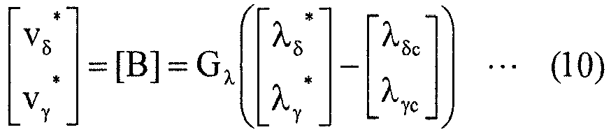
-
FIG. 5 is a block diagram illustrating the configuration of a voltagecommand calculation unit 102 in this embodiment. The voltagecommand generation unit 1024 described in the first embodiment and the second embodiment is not required, and a feedbackamount calculation unit 1022 outputs a feedback amount [B] as the voltage command [vδγ*]. - Meanwhile, a feedforward
amount calculation unit 1023 calculates a feedforward amount [F] as described in the first embodiment and the second embodiment. The voltage error [Δvδγ*] employed in the first embodiment and the second embodiment is corrected by subtracting the feedforward amount [F] therefrom. In this embodiment, a symbol [Δvδγ*] is used for a voltage error that is corrected by subtracting the feedforward amount [F] therefrom. - That is to say, the voltage error [Δvδγ*] is obtained from the formula (11) below in this embodiment.
[Math 11]
- In the use of the feedback amount [B] itself as the voltage command [vδγ*], the voltage error [Δvδγ*] decided by the formula (11) can be used to determine the presence or absence of step-out as in the first embodiment. This is apparent from the formulae (4) and (5).
- The above reveals that also in this embodiment, the presence or absence of step-out can be determined by performing the process as in the first embodiment.
- Needless to say, also in this embodiment, the product of the current deviation and the feedback gain Gi may be used as the feedback amount [B] as in the second embodiment. In that case, the feedback amount [B] obtained by the formula (9) is employed as the voltage command [vδγ*]. As in the second embodiment, thus, in place of the air-gap flux [λδγc] and the command value [λδγ*] thereof, the current [iδγc] and the command value [iδγ*] thereof are input to the feedback
amount calculation unit 1022. - As described above, on what the voltage error [Δvδγ*] is based differs depending on whether only the feedback amount [B] is used or the feedforward amount [F] is also used to obtain the voltage command [vδγ*]. In the case where the voltage command [vδγ*] is not based on the feedforward amount [F], as in this embodiment, the voltage error [Δvδγ*] is set also on the basis of the feedforward amount [F]. In the case where the voltage command [vδγ*] is based on the feedforward amount [F], as in the first and second embodiments, the voltage error [Δvδγ*] is not based on the air-gap flux [λδγc] (see the second expression of the formula (5)).
- The feedforward amount [F] may be set on the basis of a term of the voltage equation except for one term. In this case, the range in which the voltage error [Δvδγ*] varies is set also on the basis of the one term.
- The coefficients eiI, eiJ, eΛ, and ev can be affected by the variations in the device constant of the
electric motor 3, as well as variations on circuit. For example, the coefficients eiI and eiJ are affected by the variations in the detector (not shown) that detects a current [ix], and the coefficient ev is affected by the variations in the detector (not shown) that detects a voltage input to the voltage control type inverter (not shown) of thevoltage supply source 2 or a voltage [vx] output therefrom. Note that the variations on the circuit, however, has a less effect on the voltage error [Δvδγ*] than the variations in the device constant of theelectric motor 3. If the variations on the circuit are disregarded, thus, step-out can actually be determined. - In the case where variations except for the variations in detector have less effects on the voltage error [Δvδγ*], step-out can be virtually determined if such variations are disregarded.
- Alternatively, for example, only the variations that affect the voltage error [Δvδγ*] most may be taken into account.
- A maximum value of the voltage error [Δvδγ*], which is a threshold to be compared with the feedback amount [B], may be calculated in advance on the worst conditions within the operation range assumable for the
electric motor 3 and may be stored. - In this case, the voltage
error calculation unit 1025 has a small amount of operations, and the memory thereof can have a small capacity. Or, a table simply showing a threshold can replace the voltageerror calculation unit 1025. - For example, thresholds are obtained in advance for respective rotation angle velocities and are stored as a table.
- Needless to say, the threshold may be set to be greater than the maximum value of the voltage error [Δvδγ*] in consideration of a margin.
- An estimated phase angle ϕc is small, and thus can be approximated to zero to obtain a threshold.
- A threshold may be obtained within an assumable range that can be taken by the estimated phase angle ϕc on the conditions on which no step-out occurs. For example, in the operation without step-out within the range of the estimated phase angle ϕc of -90° to 90° (such control is employed in, for example, primary magnetic flux control), -1 ≤ sinϕc < 1 and 0 ≤ cosϕc ≤ 1 are employed to obtain a threshold.
- When the estimated phase angle ϕc is approximated to zero or -1 ≤ sinϕc ≤ 1 and 0 ≤ cosϕc ≤ 1 are employed to obtain a threshold, the estimated phase angle ϕc itself needs not to be obtained. In the control that needs not to obtain the estimated phase angle ϕc except for obtaining a threshold, an amount of operations for obtaining the estimated phase angle ϕc (see the formula (2)) can be reduced.
- Obtaining a threshold within an assumable range that can be taken by the estimated phase angle ϕc on the conditions on which no step-out occurs is advantageous in that an abnormality can be determined also in the case of the operation range beyond expectation.
- The various embodiments and variations above can be appropriately combined with each other unless their functions are impaired.
- The block diagrams above are schematic, and the respective units can be configured as hardware or can be configured as a microcomputer (including a memory device) whose functions are implemented by software. Various procedures executed by the respective units or some or all of the means or functions implemented thereby may be implemented by hardware.
- The microcomputer executes the respective process steps (in other words, a procedure) described in a program. The memory device above can be constituted of one or a plurality of memory devices such as a ROM (Read Only Memory), a RAM (Random Access Memory), a rewritable nonvolatile memory (EPROM (Erasable Programmable ROM) or the like), and a hard disk unit. The memory device stores therein, for example, various types of information and data, stores therein a program to be executed by the microcomputer, and provides a work area for execution of the program. It can be understood that the microcomputer functions as various means corresponding to the respective process steps described in the program or that the microcomputer implements various functions corresponding to the respective process steps.
- While the invention has been shown and described in detail, the foregoing description is in all aspects illustrative and not restrictive. It is therefore understood that numerous modifications and variations can be devised without departing from the scope of the invention.
Claims (9)
- A controller for an electric motor, said controller controlling a synchronous motor (3), said controller comprising:an electric motor drive unit (2, 104) that applies a voltage ([vx*]) to said synchronous motor on the basis of a voltage command ([vδγ*]);a feedback amount calculation unit (1022) that decides a feedback amount based on a deviation of a current ([iδγc]) flowing through said synchronous motor from a command value ([iδγ*]) of said current or a deviation of an air-gap flux ([λδγc]) in said synchronous motor from a command value ([λδγ*]) of said air-gap flux;a voltage command generation unit (1024) that generates said voltage command on the basis of said feedback amount;a voltage error calculation unit (1025) that calculates a range in which an error ([Δvδγ*]) between a voltage value based on a voltage equation of said synchronous motor and said voltage command varies; anda determination unit (109) that determines an occurrence of an abnormality in said synchronous motor when said feedback amount deviates from the range in which said error varies.
- The controller for an electric motor according to claim 1, wherein said error ([Δvδγ*]) is set on the basis of a variation range decided by at least one of said current ([iδγc]), said voltage command ([vδγ*]), a manufacturing tolerance or a range of guarantee of an operating temperature of said synchronous motor (3), a manufacturing tolerance or a range of guarantee of an operating temperature of said electric motor drive unit, a manufacturing tolerance or a range of guarantee or an operating temperature of a detector that detects said current or said voltage, or a rotation angle velocity (ω1) of said synchronous motor.
- The controller for an electric motor according to claim 1, wherein the range in which said error ([Δvδγ*]) varies is set on the basis of a variation range decided by at least one of a range in which an error (eiI[I][iδγc]) that is parallel in phase with said current ([iδγc]) varies, a range in which an error (eiJ[J][iδγc]) that is orthogonal in phase to said current varies, a range in which an error (eΛ[sinϕc cosϕc]t) that is orthogonal in phase to a field flux ([Λ0]) of said synchronous motor (3) varies, or a range in which an error (ev[vδγ*]) that is parallel in phase with said voltage command ([vδγ*]) varies.
- The controller for an electric motor according to claim 2, wherein the range in which said error ([Δvδγ*]) varies is set on the basis of a variation range decided by at least one of a range in which an error (eiI[I][iδγc]) that is parallel in phase with said current ([iδγc]) varies, a range in which an error (eiJ[J][iδγc]) that is orthogonal in phase to said current varies, a range in which an error (eΛ[sinϕc cosϕc]t) that is orthogonal in phase to a field flux ([Λ0]) of said synchronous motor (3) varies, or a range in which an error (ev[vδγ*]) that is parallel in phase with said voltage command ([vδγ*]) varies.
- The controller for an electric motor according to claim 2, wherein the range in which said error ([Δvδγ*]) varies is set by a maximum value and/or a minimum value in a combination of an upper limit and a lower limit of said variation range, said current ([iδγc]), and said voltage command ([vδγ*]).
- The controller for an electric motor according to claim 3, wherein the range in which said error ([Δvδγ*]) varies is set by a maximum value and/or a minimum value in a combination of an upper limit and a lower limit of said variation range, said current ([iδγc]), and said voltage command ([vδγ*]).
- The controller for an electric motor according to claim 4, wherein the range in which said error ([Δvδγ*]) varies is set by a maximum value and/or a minimum value in a combination of an upper limit and a lower limit of said variation range, said current ([iδγc]), and said voltage command ([vδγ*]).
- The controller for an electric motor according to any one of claims 1 to 7, wherein
the range in which said error ([Δvδγ*]) varies is further set also on the basis of one term of said voltage equation,
said controller further comprises a feedforward amount calculation unit (1023) that decides a feedforward amount ([F]) based on a term of said voltage equation except for said one term, and
said voltage command generation unit (1024) further generates said voltage command ([vδγ*]) also on the basis of said feedforward amount. - The controller for an electric motor according to any one of claims 1 to 7, further comprising
a feedforward amount calculation unit (1023) that decides a feedforward amount ([F]) based on said voltage equation,
wherein said voltage command generation unit (1024) further generates said voltage command ([vδγ*]) also on the basis of said feedforward amount ([F]).
Applications Claiming Priority (2)
| Application Number | Priority Date | Filing Date | Title |
|---|---|---|---|
| JP2014003101A JP5854058B2 (en) | 2014-01-10 | 2014-01-10 | Electric motor control device |
| PCT/JP2015/050120 WO2015105093A1 (en) | 2014-01-10 | 2015-01-06 | Control device for electric motor |
Publications (3)
| Publication Number | Publication Date |
|---|---|
| EP3093985A1 true EP3093985A1 (en) | 2016-11-16 |
| EP3093985A4 EP3093985A4 (en) | 2018-01-03 |
| EP3093985B1 EP3093985B1 (en) | 2025-02-26 |
Family
ID=53523918
Family Applications (1)
| Application Number | Title | Priority Date | Filing Date |
|---|---|---|---|
| EP15735188.3A Active EP3093985B1 (en) | 2014-01-10 | 2015-01-06 | Control device for electric motor |
Country Status (7)
| Country | Link |
|---|---|
| US (1) | US10298158B2 (en) |
| EP (1) | EP3093985B1 (en) |
| JP (1) | JP5854058B2 (en) |
| KR (1) | KR101667908B1 (en) |
| CN (1) | CN105830336B (en) |
| AU (1) | AU2015205227B2 (en) |
| WO (1) | WO2015105093A1 (en) |
Families Citing this family (2)
| Publication number | Priority date | Publication date | Assignee | Title |
|---|---|---|---|---|
| KR102362338B1 (en) * | 2014-02-28 | 2022-02-11 | 메르크 파텐트 게엠베하 | Materials for organic light-emitting devices |
| JP2017051016A (en) * | 2015-09-03 | 2017-03-09 | Ntn株式会社 | Vehicle motor drive device and vehicle equipped with the same |
Family Cites Families (20)
| Publication number | Priority date | Publication date | Assignee | Title |
|---|---|---|---|---|
| US6281656B1 (en) * | 1998-09-30 | 2001-08-28 | Hitachi, Ltd. | Synchronous motor control device electric motor vehicle control device and method of controlling synchronous motor |
| JP4319112B2 (en) * | 2004-08-27 | 2009-08-26 | 三菱電機株式会社 | Electric power steering device |
| JP4928850B2 (en) * | 2006-06-28 | 2012-05-09 | 株式会社東芝 | Rotating machine control device |
| JP4621997B2 (en) * | 2006-07-10 | 2011-02-02 | 株式会社デンソー | Fuel pump control device |
| JP4771998B2 (en) | 2006-09-05 | 2011-09-14 | 三菱電機株式会社 | Electric motor drive |
| EP2075906A4 (en) * | 2006-10-19 | 2013-09-11 | Mitsubishi Electric Corp | VECTOR CONTROL OF A PERMANENT MAGNET SYNCHRONOUS MOTOR |
| JP4918870B2 (en) * | 2007-02-26 | 2012-04-18 | 株式会社ジェイテクト | Motor control device and electric power steering device |
| JP5282376B2 (en) * | 2007-06-29 | 2013-09-04 | 日本精工株式会社 | Electric power steering device |
| US8344680B2 (en) | 2007-12-04 | 2013-01-01 | Mitsubishi Electric Corporation | Control apparatus of alternating-current motor |
| JP2010051151A (en) | 2008-08-25 | 2010-03-04 | Jtekt Corp | Motor control apparatus |
| JP5327700B2 (en) * | 2008-10-02 | 2013-10-30 | 株式会社安川電機 | Induction motor control device and control method thereof |
| US8242721B2 (en) * | 2008-10-31 | 2012-08-14 | R&D Dynamics Corporation | Position-sensorless control system and method of operation for a synchronous motor |
| JP2010252503A (en) | 2009-04-15 | 2010-11-04 | Meidensha Corp | Position and speed sensorless controller of pm motor |
| JP5328592B2 (en) | 2009-10-02 | 2013-10-30 | オムロンオートモーティブエレクトロニクス株式会社 | Motor drive device |
| JP5195888B2 (en) * | 2010-06-24 | 2013-05-15 | 株式会社デンソー | Electric motor drive device and electric power steering device using the same |
| JP5353867B2 (en) * | 2010-12-02 | 2013-11-27 | 株式会社デンソー | Rotating machine control device |
| EP2671312B1 (en) * | 2011-02-02 | 2014-11-05 | Telefonaktiebolaget L M Ericsson (publ) | Digital control unit having a transient detector for controlling a switched mode power supply |
| JP5348153B2 (en) * | 2011-02-14 | 2013-11-20 | 株式会社デンソー | Rotating machine control device |
| JP5603360B2 (en) * | 2011-06-24 | 2014-10-08 | 三菱電機株式会社 | Motor control device and electric power steering device using the same |
| JP5880967B2 (en) * | 2012-09-28 | 2016-03-09 | 株式会社デンソー | AC motor control device |
-
2014
- 2014-01-10 JP JP2014003101A patent/JP5854058B2/en active Active
-
2015
- 2015-01-06 WO PCT/JP2015/050120 patent/WO2015105093A1/en not_active Ceased
- 2015-01-06 KR KR1020167017594A patent/KR101667908B1/en active Active
- 2015-01-06 US US15/105,159 patent/US10298158B2/en active Active
- 2015-01-06 EP EP15735188.3A patent/EP3093985B1/en active Active
- 2015-01-06 CN CN201580003046.1A patent/CN105830336B/en active Active
- 2015-01-06 AU AU2015205227A patent/AU2015205227B2/en active Active
Also Published As
| Publication number | Publication date |
|---|---|
| US20170005603A1 (en) | 2017-01-05 |
| CN105830336B (en) | 2019-11-26 |
| KR20160085903A (en) | 2016-07-18 |
| KR101667908B1 (en) | 2016-10-19 |
| AU2015205227A1 (en) | 2016-06-30 |
| AU2015205227B2 (en) | 2017-08-31 |
| EP3093985B1 (en) | 2025-02-26 |
| JP2015133794A (en) | 2015-07-23 |
| EP3093985A4 (en) | 2018-01-03 |
| US10298158B2 (en) | 2019-05-21 |
| WO2015105093A1 (en) | 2015-07-16 |
| CN105830336A (en) | 2016-08-03 |
| JP5854058B2 (en) | 2016-02-09 |
Similar Documents
| Publication | Publication Date | Title |
|---|---|---|
| KR102108911B1 (en) | Drive system and inverter device | |
| EP2892147B1 (en) | Electric motor control device | |
| JP5130031B2 (en) | Position sensorless control device for permanent magnet motor | |
| JP6008264B2 (en) | Magnetic pole position detection device for permanent magnet type synchronous motor | |
| JP4517793B2 (en) | Permanent magnet synchronous motor control device and module | |
| JP6361450B2 (en) | Induction motor control device | |
| CN104718694A (en) | Synchronous machine control device | |
| US10298158B2 (en) | Controller for electric motor | |
| EP3703249B1 (en) | Power conversion device and controlling method therefor | |
| JP5660191B2 (en) | Electric motor control device | |
| JP4667741B2 (en) | Induction motor control device | |
| JP5768255B2 (en) | Control device for permanent magnet synchronous motor | |
| JP7627204B2 (en) | Power Conversion Equipment | |
| JP5854057B2 (en) | Step-out detection device and motor drive system | |
| CN112715003A (en) | Control device for AC rotating machine | |
| JP2007336645A (en) | Control device for synchronous machine | |
| JP5983636B2 (en) | Electric motor control device | |
| JP6582393B2 (en) | Control device for motor drive device | |
| JP7628071B2 (en) | Power Conversion Equipment | |
| JP7704021B2 (en) | Motor control method and motor control device | |
| EP4391356A1 (en) | Current detection device, current detection program, and current detection method | |
| JP5502044B2 (en) | Control device and control method for rotating electrical machine | |
| AU2013310516B9 (en) | Electric motor control device | |
| JP6015647B2 (en) | Control device for motor drive device and motor drive system | |
| JP2017135869A (en) | Controller for synchronous electric motor |
Legal Events
| Date | Code | Title | Description |
|---|---|---|---|
| PUAI | Public reference made under article 153(3) epc to a published international application that has entered the european phase |
Free format text: ORIGINAL CODE: 0009012 |
|
| 17P | Request for examination filed |
Effective date: 20160608 |
|
| AK | Designated contracting states |
Kind code of ref document: A1 Designated state(s): AL AT BE BG CH CY CZ DE DK EE ES FI FR GB GR HR HU IE IS IT LI LT LU LV MC MK MT NL NO PL PT RO RS SE SI SK SM TR |
|
| AX | Request for extension of the european patent |
Extension state: BA ME |
|
| DAX | Request for extension of the european patent (deleted) | ||
| A4 | Supplementary search report drawn up and despatched |
Effective date: 20171201 |
|
| RIC1 | Information provided on ipc code assigned before grant |
Ipc: H02P 21/18 20160101ALI20171127BHEP Ipc: H02P 25/024 20160101ALI20171127BHEP Ipc: H02P 21/00 20160101AFI20171127BHEP Ipc: H02P 6/12 20060101ALI20171127BHEP Ipc: H02P 8/38 20060101ALI20171127BHEP Ipc: H02P 27/04 20160101ALI20171127BHEP Ipc: H02P 29/032 20160101ALI20171127BHEP |
|
| STAA | Information on the status of an ep patent application or granted ep patent |
Free format text: STATUS: EXAMINATION IS IN PROGRESS |
|
| 17Q | First examination report despatched |
Effective date: 20200707 |
|
| RAP3 | Party data changed (applicant data changed or rights of an application transferred) |
Owner name: DAIKIN INDUSTRIES, LTD. |
|
| P01 | Opt-out of the competence of the unified patent court (upc) registered |
Effective date: 20230525 |
|
| GRAP | Despatch of communication of intention to grant a patent |
Free format text: ORIGINAL CODE: EPIDOSNIGR1 |
|
| STAA | Information on the status of an ep patent application or granted ep patent |
Free format text: STATUS: GRANT OF PATENT IS INTENDED |
|
| INTG | Intention to grant announced |
Effective date: 20240920 |
|
| GRAS | Grant fee paid |
Free format text: ORIGINAL CODE: EPIDOSNIGR3 |
|
| GRAA | (expected) grant |
Free format text: ORIGINAL CODE: 0009210 |
|
| STAA | Information on the status of an ep patent application or granted ep patent |
Free format text: STATUS: THE PATENT HAS BEEN GRANTED |
|
| AK | Designated contracting states |
Kind code of ref document: B1 Designated state(s): AL AT BE BG CH CY CZ DE DK EE ES FI FR GB GR HR HU IE IS IT LI LT LU LV MC MK MT NL NO PL PT RO RS SE SI SK SM TR |
|
| REG | Reference to a national code |
Ref country code: GB Ref legal event code: FG4D |
|
| REG | Reference to a national code |
Ref country code: CH Ref legal event code: EP |
|
| REG | Reference to a national code |
Ref country code: DE Ref legal event code: R096 Ref document number: 602015091093 Country of ref document: DE |
|
| REG | Reference to a national code |
Ref country code: IE Ref legal event code: FG4D |
|
| REG | Reference to a national code |
Ref country code: NL Ref legal event code: MP Effective date: 20250226 |
|
| PG25 | Lapsed in a contracting state [announced via postgrant information from national office to epo] |
Ref country code: RS Free format text: LAPSE BECAUSE OF FAILURE TO SUBMIT A TRANSLATION OF THE DESCRIPTION OR TO PAY THE FEE WITHIN THE PRESCRIBED TIME-LIMIT Effective date: 20250526 |
|
| PG25 | Lapsed in a contracting state [announced via postgrant information from national office to epo] |
Ref country code: FI Free format text: LAPSE BECAUSE OF FAILURE TO SUBMIT A TRANSLATION OF THE DESCRIPTION OR TO PAY THE FEE WITHIN THE PRESCRIBED TIME-LIMIT Effective date: 20250226 |
|
| PG25 | Lapsed in a contracting state [announced via postgrant information from national office to epo] |
Ref country code: PL Free format text: LAPSE BECAUSE OF FAILURE TO SUBMIT A TRANSLATION OF THE DESCRIPTION OR TO PAY THE FEE WITHIN THE PRESCRIBED TIME-LIMIT Effective date: 20250226 |
|
| PG25 | Lapsed in a contracting state [announced via postgrant information from national office to epo] |
Ref country code: ES Free format text: LAPSE BECAUSE OF FAILURE TO SUBMIT A TRANSLATION OF THE DESCRIPTION OR TO PAY THE FEE WITHIN THE PRESCRIBED TIME-LIMIT Effective date: 20250226 |
|
| REG | Reference to a national code |
Ref country code: LT Ref legal event code: MG9D |
|
| PG25 | Lapsed in a contracting state [announced via postgrant information from national office to epo] |
Ref country code: IS Free format text: LAPSE BECAUSE OF FAILURE TO SUBMIT A TRANSLATION OF THE DESCRIPTION OR TO PAY THE FEE WITHIN THE PRESCRIBED TIME-LIMIT Effective date: 20250626 Ref country code: NO Free format text: LAPSE BECAUSE OF FAILURE TO SUBMIT A TRANSLATION OF THE DESCRIPTION OR TO PAY THE FEE WITHIN THE PRESCRIBED TIME-LIMIT Effective date: 20250526 |
|
| PG25 | Lapsed in a contracting state [announced via postgrant information from national office to epo] |
Ref country code: NL Free format text: LAPSE BECAUSE OF FAILURE TO SUBMIT A TRANSLATION OF THE DESCRIPTION OR TO PAY THE FEE WITHIN THE PRESCRIBED TIME-LIMIT Effective date: 20250226 |
|
| PG25 | Lapsed in a contracting state [announced via postgrant information from national office to epo] |
Ref country code: HR Free format text: LAPSE BECAUSE OF FAILURE TO SUBMIT A TRANSLATION OF THE DESCRIPTION OR TO PAY THE FEE WITHIN THE PRESCRIBED TIME-LIMIT Effective date: 20250226 |
|
| PG25 | Lapsed in a contracting state [announced via postgrant information from national office to epo] |
Ref country code: PT Free format text: LAPSE BECAUSE OF FAILURE TO SUBMIT A TRANSLATION OF THE DESCRIPTION OR TO PAY THE FEE WITHIN THE PRESCRIBED TIME-LIMIT Effective date: 20250626 Ref country code: LV Free format text: LAPSE BECAUSE OF FAILURE TO SUBMIT A TRANSLATION OF THE DESCRIPTION OR TO PAY THE FEE WITHIN THE PRESCRIBED TIME-LIMIT Effective date: 20250226 |
|
| PG25 | Lapsed in a contracting state [announced via postgrant information from national office to epo] |
Ref country code: GR Free format text: LAPSE BECAUSE OF FAILURE TO SUBMIT A TRANSLATION OF THE DESCRIPTION OR TO PAY THE FEE WITHIN THE PRESCRIBED TIME-LIMIT Effective date: 20250527 Ref country code: BG Free format text: LAPSE BECAUSE OF FAILURE TO SUBMIT A TRANSLATION OF THE DESCRIPTION OR TO PAY THE FEE WITHIN THE PRESCRIBED TIME-LIMIT Effective date: 20250226 |
|
| REG | Reference to a national code |
Ref country code: AT Ref legal event code: MK05 Ref document number: 1771669 Country of ref document: AT Kind code of ref document: T Effective date: 20250226 |
|
| PG25 | Lapsed in a contracting state [announced via postgrant information from national office to epo] |
Ref country code: SE Free format text: LAPSE BECAUSE OF FAILURE TO SUBMIT A TRANSLATION OF THE DESCRIPTION OR TO PAY THE FEE WITHIN THE PRESCRIBED TIME-LIMIT Effective date: 20250226 |
|
| PG25 | Lapsed in a contracting state [announced via postgrant information from national office to epo] |
Ref country code: SM Free format text: LAPSE BECAUSE OF FAILURE TO SUBMIT A TRANSLATION OF THE DESCRIPTION OR TO PAY THE FEE WITHIN THE PRESCRIBED TIME-LIMIT Effective date: 20250226 |
|
| PG25 | Lapsed in a contracting state [announced via postgrant information from national office to epo] |
Ref country code: DK Free format text: LAPSE BECAUSE OF FAILURE TO SUBMIT A TRANSLATION OF THE DESCRIPTION OR TO PAY THE FEE WITHIN THE PRESCRIBED TIME-LIMIT Effective date: 20250226 |
|
| PG25 | Lapsed in a contracting state [announced via postgrant information from national office to epo] |
Ref country code: IT Free format text: LAPSE BECAUSE OF FAILURE TO SUBMIT A TRANSLATION OF THE DESCRIPTION OR TO PAY THE FEE WITHIN THE PRESCRIBED TIME-LIMIT Effective date: 20250226 |
|
| PG25 | Lapsed in a contracting state [announced via postgrant information from national office to epo] |
Ref country code: AT Free format text: LAPSE BECAUSE OF FAILURE TO SUBMIT A TRANSLATION OF THE DESCRIPTION OR TO PAY THE FEE WITHIN THE PRESCRIBED TIME-LIMIT Effective date: 20250226 |
|
| PG25 | Lapsed in a contracting state [announced via postgrant information from national office to epo] |
Ref country code: EE Free format text: LAPSE BECAUSE OF FAILURE TO SUBMIT A TRANSLATION OF THE DESCRIPTION OR TO PAY THE FEE WITHIN THE PRESCRIBED TIME-LIMIT Effective date: 20250226 Ref country code: CZ Free format text: LAPSE BECAUSE OF FAILURE TO SUBMIT A TRANSLATION OF THE DESCRIPTION OR TO PAY THE FEE WITHIN THE PRESCRIBED TIME-LIMIT Effective date: 20250226 |
|
| PG25 | Lapsed in a contracting state [announced via postgrant information from national office to epo] |
Ref country code: RO Free format text: LAPSE BECAUSE OF FAILURE TO SUBMIT A TRANSLATION OF THE DESCRIPTION OR TO PAY THE FEE WITHIN THE PRESCRIBED TIME-LIMIT Effective date: 20250226 |
|
| PG25 | Lapsed in a contracting state [announced via postgrant information from national office to epo] |
Ref country code: SK Free format text: LAPSE BECAUSE OF FAILURE TO SUBMIT A TRANSLATION OF THE DESCRIPTION OR TO PAY THE FEE WITHIN THE PRESCRIBED TIME-LIMIT Effective date: 20250226 |
|
| REG | Reference to a national code |
Ref country code: DE Ref legal event code: R097 Ref document number: 602015091093 Country of ref document: DE |
|
| PLBE | No opposition filed within time limit |
Free format text: ORIGINAL CODE: 0009261 |
|
| STAA | Information on the status of an ep patent application or granted ep patent |
Free format text: STATUS: NO OPPOSITION FILED WITHIN TIME LIMIT |
|
| 26N | No opposition filed |
Effective date: 20251127 |
|
| PGFP | Annual fee paid to national office [announced via postgrant information from national office to epo] |
Ref country code: GB Payment date: 20260123 Year of fee payment: 12 |
|
| PGFP | Annual fee paid to national office [announced via postgrant information from national office to epo] |
Ref country code: DE Payment date: 20260121 Year of fee payment: 12 |
|
| PGFP | Annual fee paid to national office [announced via postgrant information from national office to epo] |
Ref country code: FR Payment date: 20260123 Year of fee payment: 12 |
|
| PG25 | Lapsed in a contracting state [announced via postgrant information from national office to epo] |
Ref country code: LT Free format text: LAPSE BECAUSE OF FAILURE TO SUBMIT A TRANSLATION OF THE DESCRIPTION OR TO PAY THE FEE WITHIN THE PRESCRIBED TIME-LIMIT Effective date: 20250226 |