EP3093642B1 - Tire rolling-resistance testing method and testing device - Google Patents
Tire rolling-resistance testing method and testing device Download PDFInfo
- Publication number
- EP3093642B1 EP3093642B1 EP14879432.4A EP14879432A EP3093642B1 EP 3093642 B1 EP3093642 B1 EP 3093642B1 EP 14879432 A EP14879432 A EP 14879432A EP 3093642 B1 EP3093642 B1 EP 3093642B1
- Authority
- EP
- European Patent Office
- Prior art keywords
- tire
- tangential force
- rolling resistance
- drum
- force
- Prior art date
- Legal status (The legal status is an assumption and is not a legal conclusion. Google has not performed a legal analysis and makes no representation as to the accuracy of the status listed.)
- Active
Links
- 238000012360 testing method Methods 0.000 title claims description 47
- 238000005096 rolling process Methods 0.000 claims description 65
- 238000005259 measurement Methods 0.000 claims description 63
- 230000002159 abnormal effect Effects 0.000 claims description 14
- 238000000034 method Methods 0.000 claims description 8
- 230000003071 parasitic effect Effects 0.000 description 14
- 230000007423 decrease Effects 0.000 description 5
- 230000005856 abnormality Effects 0.000 description 3
- GNFTZDOKVXKIBK-UHFFFAOYSA-N 3-(2-methoxyethoxy)benzohydrazide Chemical compound COCCOC1=CC=CC(C(=O)NN)=C1 GNFTZDOKVXKIBK-UHFFFAOYSA-N 0.000 description 2
- FGUUSXIOTUKUDN-IBGZPJMESA-N C1(=CC=CC=C1)N1C2=C(NC([C@H](C1)NC=1OC(=NN=1)C1=CC=CC=C1)=O)C=CC=C2 Chemical compound C1(=CC=CC=C1)N1C2=C(NC([C@H](C1)NC=1OC(=NN=1)C1=CC=CC=C1)=O)C=CC=C2 FGUUSXIOTUKUDN-IBGZPJMESA-N 0.000 description 2
- YTAHJIFKAKIKAV-XNMGPUDCSA-N [(1R)-3-morpholin-4-yl-1-phenylpropyl] N-[(3S)-2-oxo-5-phenyl-1,3-dihydro-1,4-benzodiazepin-3-yl]carbamate Chemical compound O=C1[C@H](N=C(C2=C(N1)C=CC=C2)C1=CC=CC=C1)NC(O[C@H](CCN1CCOCC1)C1=CC=CC=C1)=O YTAHJIFKAKIKAV-XNMGPUDCSA-N 0.000 description 2
- 238000013459 approach Methods 0.000 description 2
- 238000012937 correction Methods 0.000 description 2
- 238000010586 diagram Methods 0.000 description 2
- 238000011156 evaluation Methods 0.000 description 2
- 238000010998 test method Methods 0.000 description 2
- 230000000694 effects Effects 0.000 description 1
- 244000045947 parasite Species 0.000 description 1
- 238000012545 processing Methods 0.000 description 1
- 239000002699 waste material Substances 0.000 description 1
Images


Classifications
-
- G—PHYSICS
- G01—MEASURING; TESTING
- G01M—TESTING STATIC OR DYNAMIC BALANCE OF MACHINES OR STRUCTURES; TESTING OF STRUCTURES OR APPARATUS, NOT OTHERWISE PROVIDED FOR
- G01M17/00—Testing of vehicles
- G01M17/007—Wheeled or endless-tracked vehicles
- G01M17/02—Tyres
- G01M17/022—Tyres the tyre co-operating with rotatable rolls
-
- B—PERFORMING OPERATIONS; TRANSPORTING
- B60—VEHICLES IN GENERAL
- B60C—VEHICLE TYRES; TYRE INFLATION; TYRE CHANGING; CONNECTING VALVES TO INFLATABLE ELASTIC BODIES IN GENERAL; DEVICES OR ARRANGEMENTS RELATED TO TYRES
- B60C99/00—Subject matter not provided for in other groups of this subclass
-
- G—PHYSICS
- G01—MEASURING; TESTING
- G01M—TESTING STATIC OR DYNAMIC BALANCE OF MACHINES OR STRUCTURES; TESTING OF STRUCTURES OR APPARATUS, NOT OTHERWISE PROVIDED FOR
- G01M17/00—Testing of vehicles
- G01M17/007—Wheeled or endless-tracked vehicles
- G01M17/0072—Wheeled or endless-tracked vehicles the wheels of the vehicle co-operating with rotatable rolls
- G01M17/0074—Details, e.g. roller construction, vehicle restraining devices
-
- G—PHYSICS
- G01—MEASURING; TESTING
- G01M—TESTING STATIC OR DYNAMIC BALANCE OF MACHINES OR STRUCTURES; TESTING OF STRUCTURES OR APPARATUS, NOT OTHERWISE PROVIDED FOR
- G01M17/00—Testing of vehicles
- G01M17/007—Wheeled or endless-tracked vehicles
- G01M17/0072—Wheeled or endless-tracked vehicles the wheels of the vehicle co-operating with rotatable rolls
- G01M17/0076—Two-wheeled vehicles
-
- G—PHYSICS
- G01—MEASURING; TESTING
- G01M—TESTING STATIC OR DYNAMIC BALANCE OF MACHINES OR STRUCTURES; TESTING OF STRUCTURES OR APPARATUS, NOT OTHERWISE PROVIDED FOR
- G01M17/00—Testing of vehicles
- G01M17/007—Wheeled or endless-tracked vehicles
- G01M17/013—Wheels
Landscapes
- Physics & Mathematics (AREA)
- General Physics & Mathematics (AREA)
- Engineering & Computer Science (AREA)
- Mechanical Engineering (AREA)
- Tires In General (AREA)
Description
- The present invention relates to a tire rolling resistance testing method and testing device capable of improving measurement accuracy and reliability of rolling resistance.
- As one of test methods for measuring rolling resistance of a tire, a force method described in JIS D4234 is well known. In this method, as illustrated in
FIG. 6 , a tire T is rotated by being pushed against an outer surface of a drum (a) that rotates at a predetermined speed V (e.g., 80 km/h in case of passenger car tires) with a predetermined vertical load (e.g., 80% of the maximum load capacity in case of passenger car tires). Then a tangential force Fx acting on the tire axle (b) is measured by a force component meter attached to the tire axle (b), and then the rolling resistance Fr is calculated based on the tangential force Fx. - Note that the tangential force Fx includes resistance of a bearing on the tire axle and parasitic loss of the air resistance on the tire T and the drum (a). Accordingly, a correction of the axial force Fx takes place to remove the parasitic loss. Here, the parasitic loss is measured by the skim test (e.g., JIS D4234) which is performed subsequent to the measurement of the tangential force Fx.
- On the other hand, the force component meter amplifies a signal obtained from a sensor by an amplifier because the signal is very weak. At that time, however, "drift" in which an operating point of the amplifier shifts occurs, and it brings a problem of divergence between the actual value and the displayed value. Drift is a phenomenon that an output of the amplifier varies gradually so as to shift the zero point in the state without the addition of input signals to the two input terminals. The reason for this can be found such as variations in the temperature characteristics of transistors.
- In the prior art, drift amount of an amplifier to the time was previously obtained through actual measurement and stored. A technique that corrects a value of the tangential force Fx measured by offsetting the drift amount based on the information has been proposed. Unfortunately, the drift amount is different by not only a rotational direction of the tire at the time of measurement but also each tire. Thus, it has been difficult to correct the drift amount accurately from the tangential force Fx, and therefore a fully satisfactory accuracy has not yet been achieved.
- The following
Patent Document 1 relates to the correction of the drift amount. - Patent Document 1: Japanese Unexamined Patent Application Publication
S56-51641 - The present invention has an object to provide a tire rolling-resistance testing method and testing device capable of improving the measurement accuracy and reliability of rolling resistance by identifying and excluding an abnormal measurement of rolling resistance value due to drift, based on measuring drift amount after completing measurement of a tangential force Fx, and comparing the drift amount with a previously determined threshold value KA.
- The first aspect in accordance with the invention provides a tire rolling resistance testing method for measuring rolling resistance of a tire based on a tangential force (Fx) acting on a tire axle upon the tire rotating by being pushed against an outer surface of a rotating drum, the method including the steps of:
- a zero point adjustment step of adjusting a value of a component force meter to zero point after mounting the tire inflated on the tire axle;
- a rolling resistance measurement step of measuring a tangential force (Fx) acting on the tire axle using the component force meter upon the tire rotating with a load by being pushed against the outer surface of the rotating drum; and
- a determination step including:
- measuring a tangential force (FxA) of the tire axle in a stop state of the tire being separated from the drum with no load, after the rolling resistance measurement step;
- comparing the tangential force (FxA) with a previously determined threshold value (KA); and
- determining the test as abnormal in case of the tangential force (FxA) exceeding the threshold value (KA).
- In the tire rolling resistance testing method according to the invention, the tangential force (Fx) may be measured upon the tire rotating in a first direction with a load by being pushed against the outer surface of the rotating drum in the rolling resistance measurement.
- In the tire rolling resistance testing method according to the invention, the rolling resistance measurement step may include a first rotation direction measurement step of measuring a tangential force (Fx1) from the tire rotating in a first direction, and a second rotation direction measurement step of measuring a tangential force (Fx2) from the tire rotating in a second direction, with a load by being pushed against the outer surface of the rotating drum.
- In the tire rolling resistance testing method according to the invention, the rolling resistance measurement step may further include an intermediate determination step between the first rotation direction measurement step and the second rotation direction measurement step, and the intermediate determination step may include measuring a tangential force (FxB) of the tire axle in a stop state of the tire being separated from the drum with no load, after the first rotation direction measurement step, comparing the tangential force (FxB) with a previously determined threshold value (KB), and stopping the test as abnormal in case of the tangential force (FxB) exceeding the threshold value (KB).
- The second aspect in accordance with the invention provides a tire rolling resistance testing device for performing the rolling resistance testing method, wherein the device includes a determination means to determine a result of the test abnormal in case of the tangential force (FxA) exceeding the threshold value (KA).
- The present invention includes the determination step as described above. In the determination step, a tangential force FxA of the tire axle in the stop state of the tire separated from the drum with no load, i.e., drift amount is measured after the rolling resistance measurement step. Then, the drift amount (the tangential force FxA) is compared with a previously determined threshold value KA, and the test is determined as abnormal when the drift amount exceeds the threshold value KA.
- That is, the present invention is possible to identify and exclude an abnormal measurement of rolling resistance value due to drift of the force component meter. Thus, the present invention may suppress decreases in reliability and accuracy of rolling resistance which are caused by abnormal measurement of rolling resistance. As a result, the present invention may improve measurement accuracy and reliability of rolling resistance.
-
-
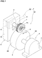
FIG. 1 is a perspective view illustrating an embodiment of a testing device for carrying out the rolling resistance testing method of a tire of the present invention. -
FIG. 2 is a conceptual diagram illustrating the rolling resistance testing method. -
FIG. 3 is a flowchart illustrating the rolling resistance testing method. -
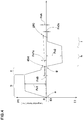
FIG. 4 is a graph showing a relationship between a tangential force measured on the basis of the flow chart and an elapsed time of the test. -
FIG. 5 is a graph illustrating an example of a method for calculating the rolling resistance. -
FIG. 6 is a conceptual diagram illustrating a conventional rolling resistance test method by the force method. - Hereinafter, an embodiment of the present invention will be described in detail. As illustrated in
FIG. 1 , a rollingresistance testing device 1 of a tire in accordance with the present embodiment (simply referred to as "rollingresistance testing device 1") includes amain body 1A and adetermination unit 1B. - The
main body 1A is configured to be able to measure rolling resistance Fr of a tire based on a tangential force Fx acting on atire axle 3 when the tire is rotated by being pushed against anouter surface 2S of adrum 2 which is rotating. Specifically, themain body 1A includes thedrum 2, adrum driving device 4, atire holder 5 and aforce component meter 6. Theouter surface 2S of thedrum 2 is configured as a road surface for the tire. Thedrum driving device 4 drives thedrum 2 around its central axis. Thetire holder 5 is configured to rotatably support the tire T and to be able to press the held tire T against theouter surface 2S of thedrum 2 to rotate the tire T. Theforce component meter 6 is configured to measure a tangential force Fx generating on thetire axle 3 of the tire T which is rotating. Note that themain body 1A may include an internal pressure adjustment device for adjusting the inner pressure of the tire T under measurement. - The
drum driving device 4 includes adrum holder 7 and a motor (not illustrated). Thedrum holder 7 rotatably supports acentral axle 2A of thedrum 2. The motor drives thedrum 2 rotationally through an output shaft coupled to thecentral axle 2A. Then, a speed V of theouter surface 2S of the drum 2 (i.e. a running speed of the tire T) can freely be adjustable by controlling the rotational speed of the motor. - The
tire holder 5 includes abase 10, a movable table 11 and thetire axle 3. The movable table 11 is movably mounted on thebase 10 in a drum radial direction. Thetire axle 3 is arranged in parallel with thecentral axle 2A of thedrum 2, and a first end of thetire axle 3 is supported by the movable table 11. Furthermore, a second end of thetire axle 3 is supposed to rotatably support the tire T. In this embodiment, the movable table 11 is configured as a lifting table that is movable up and down. Furthermore, the movable table 11 can support the tire T such that the center axis of the tire T is located within a vertical standard plane that passes the center axis of thedrum 2. Accordingly, thetire holder 5 can vertically press the tire T mounted on thetire axle 3 with an arbitrary tire load against theouter surface 2S of thedrum 3 by a downward movement of the movable table 11. - The
force component meter 6, for example, may be fixed to a bearing of thetire axle 3, and is configured to be able to measure a tangential force Fx acting on thetire axle 3. In this embodiment, theforce component meter 6 can measure a radial force Fz acting (i.e., vertical force) on thetire axle 3 in the radial direction of the drum, at the same time, in addition to the tangential force Fx. As theforce component meter 6, a multi-component force meter such as a two-component force meter and the like can preferably be employed. - The
determination unit 1B, for example, is configured as an arithmetic processing unit or a part of it, such as a computer and the like. Then, thedetermination unit 1B performs a comparison and determination in a determination step S3 of the rolling resistance testing method described below. - Next, as conceptually illustrated in
FIG. 2 , the rolling resistance testing method is to measure rolling resistance Fr of the tire T based on a tangential force Fx acting on thetire axle 3 when the tire T is rotating by being pushed against theouter surface 2S of thedrum 2 which is rotating. - Specifically, as the flowchart illustrated in
FIG. 3 , the rolling resistance testing method includes a zero point adjustment step S1, a rolling resistance measurement step S2 and the determination step S3. In the zero point adjustment step S1, thecomponent force meter 6 is adjusted so that the indication or output signal shows zero after mounting the tire T, which has already been inflated, on thetire axle 3. - Next, in the rolling resistance measurement step S2, the tire T is forced to rotate with a load by being pushed against the
outer surface 2S of thedrum 2 which is rotating, and then a tangential force Fx acting on thetire axle 3 is measured using thecomponent force meter 6. In this embodiment, the rolling resistance measurement step S2 includes a first rotation direction measurement step S2a of measuring a tangential force Fx1 from the tire rotating in a first direction in a loaded state, a second rotation direction measurement step S2c of measuring a tangential force Fx2 from the tire rotating in a second direction in the loaded stated and an intermediate determination step S2b therebetween. - Specifically, in the first rotation direction measurement step S2a, the following steps of (a) to (d) are sequentially conducted after the zero point adjustment step S1:
- (a) applying a predetermined vertical load Fg to the tire T by pushing the tire T against the
outer surface 2S of the drum 2 (e.g., 80% of the maximum load capacity) (Step a); - (b) measuring the tangential force Fx1 in the loaded state under the vertical force Fg while being rotated the
drum 2 in the first direction at a certain speed V (e.g., 80 km/h) after a warming-up running in a certain time Ts (e.g., 30 minutes) (Step b); - (c) measuring parasitic loss which is a tangential force Fx1s at a skim running state where the tire T is rotating while maintaining the above mentioned speed V with a skim load Fs (e.g., 0.1 kN) after reducing the vertical load Fg to the skim load Fs (Step c); and
- (d) stopping the rotation of drum (Step d).
- Note that the vertical force Fg, the skim load Fs, the speed V, the time Ts for warming-up running and the like are set in accordance with specifications of the rolling resistance test such as JIS Standard (JIS D4234) and International standard (ISO 28580) and the like.
- Furthermore, in the intermediate determination step S2b, the following steps (e) and (f) are sequentially performed after the first rotation direction measurement step S2a:
- (e) measuring drift amount FxB which is a tangential force FxB at a stop state of the tire T being separated from the
drum 2 and loaded with no tire load (Step e); and - (f) comparing the tangential force (i.e., the drift amount) FxB with a previously determined threshold value KB and then determining either stopping the test as abnormal in case of the tangential force FxB exceeding the threshold value KB (FxB > KB) or continuing the test as normal in case of the tangential force FxB not exceeding the threshold value KB (FxB<=KB) (Step f).
- Furthermore, in the second rotation direction measurement step S2c, the following steps of (g) to (j) are sequentially conducted after the intermediate determination step S2b:
- (g) applying the above mentioned vertical load Fg to the tire T by pushing the tire T against the
outer surface 2S of the drum 2 (Step g); - (h) measuring the tangential force Fx2 in the loaded state under the vertical force Fg while being rotated the
drum 2 in the second direction at the above mentioned speed V after a warming-up running in the above mentioned time Ts (Step h); - (i) measuring parasitic loss which is a tangential force Fx2s at the skim running state where the tire T is rotating while maintaining the above mentioned speed V with the above mentioned skim load Fs after reducing the vertical load Fg to the skim load Fs (step i); and
- (j) stopping the rotation of drum (Step j).
- Furthermore, in the determination step S3, the following steps (k) and (1) are sequentially performed after the rolling resistance measurement step S2 (i.e., after the second rotation direction measurement step S2c in this embodiment):
- (k) measuring drift amount FxA which is a tangential force FxA at the stop state of the tire T being separated from the
drum 2 and loaded with no tire load (Step k); and - (1) comparing the tangential force FxA (i.e., the drift amount FxA) with a previously determined threshold value KA, and then determining the test as abnormal in case of the tangential force FxA exceeding the threshold value KA (Step 1).
-
FIG. 4 illustrates a graph showing a relationship between the tangential force Fx measured on the basis of the flow chart and an elapsed time of the test. As illustrated inFIG. 4 , in Step a, the tangential force Fx has not been generated since thedrum 2 is not rotated. In Step b, the tangential force Fx is increasing according to increase of the speed, and then the tangential force Fx is stabilized during the warming-up running after reaching a predetermined speed V (e.g., 80 km/h). Furthermore, the tangential force Fx1 is measured for about one minute during running after the warming-up. In Step c, the tangential force Fx decreases according to decrease of load from the vertical load Fg to the skim load Fs. Then, the tangential force Fx1s (i.e., parasite loss) is measured for about one minute during the skim running. - After stopping the rotation of the drum in Step d, Step e is subsequently performed. In the stop state with no load in Step e, the tangential force Fx has to be zero properly. Accordingly, the tangential force FxB measured in Step e is a false output based on the drift (zero-point shifting) on the
force component meter 6, and which is an error. Therefore, when the tangential force (the drift amount) FxB is large, even when corrected, it lowers the accuracy and reliability of the measurement values. Thus, Step f of the present embodiment compares the tangential force FxB (i.e., the drift amount) with a previously determined threshold value KB, and then stops the test as abnormal in case of the tangential force FxB exceeding the threshold value KB. This makes it possible to find out an measurement abnormality due to drift quickly to reduce the waste of measuring time. - Furthermore, after applying the vertical load Fg in Step g, the tire T and the
drum 2 start to rotate in the second direction. In Step h, the tangential force Fx is increasing according to increase of the speed, and then the tangential force Fx is stabilized during the warming-up running after reaching a predetermined speed V (e.g., 80 km/h). Note that the reason why the tangential force is not constant is an influence of drift of theforce component meter 6. The tangential force Fx2 is measured for about one minute during running after the warming-up. In Step i, the tangential force Fx decreases according to a decrease of load from the vertical load Fg to the skim load Fs. Then, the tangential force Fx2s (i.e., parasitic loss) is measured for about one minute during the skim running. - After stopping the rotation of the drum in Step j, Step k is subsequently performed. The tangential force FxA measured in Step k, as same as the tangential force FxB measured in Step e, is a false output based on the drift (zero-point shifting) on the
force component meter 6. Therefore, when the axial force (the drift amount) FxA is excessively large, even when corrected, it lowers the accuracy and reliability of the measurement values. Thus,Step 1 of the present embodiment compares the tangential force FxA (i.e., the drift amount) with a previously determined threshold value KA, and then determines the test as abnormal in case of the tangential force FxA exceeding the threshold value KA. This makes it possible to exclude the obtained rolling resistance Fr from the evaluation. - Although the threshold values KA and KB are not particularly limited, they are preferable to be set in consideration with a large number of tangential force FxA and FxB that is actually measured by the pre-test. Also, the comparison and determination in
step 1 is carried out by thedetermination unit 1B. - Furthermore, when FxA <= KA, the test is determined as normal, and the rolling resistance Fr is calculated based on the measured values of tangential force Fx1, tangential force Fx1s (i.e., parasitic loss), the tangential force FxB (i.e., drift amount), the tangential force Fx2, the tangential force Fx2s (i.e., parasitic loss) and the tangential force FxA (i.e., drift amount).
- As for one example of a calculating method of the rolling resistance Fr, for example, the following equation could be employed in case that the measured period for the tangential force Fx1s (parasitic loss) approaches to the measured period for the tangential force FxB (drift amount) and that the measured period for the tangential force Fx2s (parasitic loss) approaches to the measured period for the tangential force FxA (drift amount), as shown in
FIGs. 4 and5 .


drum 2 as shown inFIG. 2 , r is a distance between the axial center of thetire axle 3 during running and theouter surface 2S of thedrum 2 as shown inFIG. 2 . - As another example of the rolling resistance measurement step S2, the intermediate determination step S2b may be omitted, i.e., the rolling resistance measurement step S2 may consist of the first rotation direction measurement step S2a and the second rotation direction measurement steps S2b. In this case, the rolling resistance Fr can be calculated using the following equation;


- Furthermore, yet another example of the rolling resistance measurement step S2, the intermediate determination step S2b and the second rotation direction measurement step S2b may be omitted, i.e., the rolling resistance measurement step S2 may consist of only the first rotation direction measurement step S2a. In this case, the rolling resistance Fr can be calculated using the following equation.


- In any of the above examples, since the determination step S3 can identify the abnormalities of the test, if there is an abnormality, the obtained rolling resistance Fr can be excluded from the evaluation to improve the measurement accuracy and reliability of rolling resistance.
- While a particularly preferred embodiments of the present invention have been described in detail, the present invention is not be limited to the embodiments as shown, but it may be carried out by modifying to various aspects.
-
- 1
- Rolling resistance testing device
- 1B
- Determination unit
- 2
- Drum
- 2S
- Outer surface
- 3
- Tire axle
- 6
- Force component meter
- S1
- Zero adjustment step
- S2
- Rolling resistance measurement step
- S2a
- First rotation direction measurement step
- S2b
- Intermediate determination step
- S2c
- Second rotation direction measurement step
- S3
- Determination step
- T
- Tire
Claims (5)
- A tire rolling resistance testing method for measuring rolling resistance of a tire (T) based on a tangential force (Fx) acting on a tire axle (3) upon the tire rotating by being pushed against an outer surface (2S) of a rotating drum (2), the method comprising the steps of:a zero point adjustment step (S1) of adjusting a value of a component force meter (6) to zero point after mounting the tire (T) inflated on the tire axle (3);a rolling resistance measurement step (S2) of measuring a tangential force (Fx) acting on the tire axle (3) using the component force meter (6) upon the tire (T) rotating with a load by being pushed against the outer surface of the rotating drum (2); anda determination step (S3) comprising:measuring a tangential force (FxA) of the tire axle (3) in a stop state of the tire (T) being separated from the drum (2) with no load, after the rolling resistance measurement step (S2);comparing the tangential force (FxA) with a previously determined threshold value (KA); anddetermining the test as abnormal in case of the tangential force (FxA) exceeding the threshold value (KA).
- The tire rolling resistance testing method according to claim 1, wherein the tangential force (Fx) is measured upon the tire (T) rotating in a first direction with a load by being pushed against the outer surface (2S) of the rotating drum (2) in the rolling resistance measurement (S2)
- The tire rolling resistance testing method according to claim 1, wherein the rolling resistance measurement step (S2) comprises a first rotation direction measurement step (S2a) of measuring a tangential force (Fx1) from the tire rotating in a first direction, and a second rotation direction measurement step (S2c) of measuring a tangential force (Fx2) from the tire rotating in a second direction, with a load by being pushed against the outer surface (2S) of the rotating drum (2).
- The tire rolling resistance testing method according to claim 3,
wherein the rolling resistance measurement step (S2) further comprises an intermediate determination step (S2b) between the first rotation direction measurement step (S2a) and the second rotation direction measurement step (S2c), and the intermediate determination step (S2b) comprises
measuring a tangential force (FxB) of the tire axle (3) in a stop state of the tire (T) being separated from the drum (2) with no load, after the first rotation direction measurement step (S2a), comparing the tangential force (FxB) with a previously determined threshold value (KB), and stopping the test as abnormal in case of the tangential force (FxB) exceeding the threshold value (KB). - A tire rolling resistance testing device (1), configured to perform the rolling resistance testing method according to any one of claims 1 to 4,
wherein the device (1) comprises a determination means (1B), configured to determine a result of the test abnormal in case of the tangential force (FxA) exceeding the threshold value (KA).
Applications Claiming Priority (2)
| Application Number | Priority Date | Filing Date | Title |
|---|---|---|---|
| JP2014011612A JP5860485B2 (en) | 2014-01-24 | 2014-01-24 | Tire rolling resistance test method and test apparatus |
| PCT/JP2014/078918 WO2015111276A1 (en) | 2014-01-24 | 2014-10-30 | Tire rolling-resistance testing method and testing device |
Publications (3)
| Publication Number | Publication Date |
|---|---|
| EP3093642A1 EP3093642A1 (en) | 2016-11-16 |
| EP3093642A4 EP3093642A4 (en) | 2017-09-27 |
| EP3093642B1 true EP3093642B1 (en) | 2018-12-12 |
Family
ID=53681098
Family Applications (1)
| Application Number | Title | Priority Date | Filing Date |
|---|---|---|---|
| EP14879432.4A Active EP3093642B1 (en) | 2014-01-24 | 2014-10-30 | Tire rolling-resistance testing method and testing device |
Country Status (5)
| Country | Link |
|---|---|
| US (1) | US9885637B2 (en) |
| EP (1) | EP3093642B1 (en) |
| JP (1) | JP5860485B2 (en) |
| CN (1) | CN105899930B (en) |
| WO (1) | WO2015111276A1 (en) |
Families Citing this family (9)
| Publication number | Priority date | Publication date | Assignee | Title |
|---|---|---|---|---|
| CN106768543A (en) * | 2016-11-17 | 2017-05-31 | 安徽江淮汽车集团股份有限公司 | The test device and its method of a kind of tire drag |
| CN108692847B (en) * | 2018-05-18 | 2023-12-01 | 吉林大学 | Tire rolling resistance testing device and measuring method thereof |
| CN109030037A (en) * | 2018-06-12 | 2018-12-18 | 青岛软控机电工程有限公司 | The tangential force test device of tire high speed and test method |
| CN109297731B (en) * | 2018-11-29 | 2021-06-01 | 正新橡胶(中国)有限公司 | Control method and device for tire running test |
| CN109708903A (en) * | 2018-12-03 | 2019-05-03 | 广州小鹏汽车科技有限公司 | A kind of tire drag coefficient measuring method, system and device |
| CN110160810B (en) * | 2019-06-14 | 2020-11-24 | 青岛科技大学 | Method for testing rolling resistance of tire under indoor multiple working conditions |
| US11662276B2 (en) * | 2021-04-01 | 2023-05-30 | Citic Dicastal Co., Ltd. | Fatigue test equipment for automobile chassis simulation road test |
| CN113465948B (en) * | 2021-06-29 | 2023-10-20 | 安徽德技汽车检测中心有限公司 | Method for testing scratch resistance of car tire |
| CN114061985B (en) * | 2021-11-11 | 2023-12-01 | 厦门理工学院 | Rugged road surface analogue test platform |
Family Cites Families (17)
| Publication number | Priority date | Publication date | Assignee | Title |
|---|---|---|---|---|
| US4197736A (en) * | 1978-10-18 | 1980-04-15 | Gse, Inc. | Bi-axial load cell |
| JPS5651641A (en) * | 1979-10-04 | 1981-05-09 | Toyo Tire & Rubber Co Ltd | Tester for tire tumbling resistance |
| JP2819136B2 (en) * | 1988-10-26 | 1998-10-30 | 横浜ゴム株式会社 | Correction method of measured tire rolling resistance |
| JPH08268243A (en) * | 1995-03-31 | 1996-10-15 | Sumitomo Electric Ind Ltd | Zero point compensator of sensor for brake and method therefor |
| AU6490500A (en) * | 1999-07-16 | 2001-02-05 | Gerald R. Potts | Methods and systems for dynamic force measurement |
| JP4127062B2 (en) | 2003-01-22 | 2008-07-30 | トヨタ自動車株式会社 | Lateral acceleration sensor drift amount estimation device, lateral acceleration sensor output correction device, and road surface friction state estimation device |
| JP4265779B2 (en) * | 2004-05-14 | 2009-05-20 | 株式会社神戸製鋼所 | Tire testing machine |
| WO2005111569A1 (en) | 2004-05-14 | 2005-11-24 | Kabushiki Kaisha Kobe Seiko Sho | Tire testing machine and axis misalignment measuring method for tire testing machine |
| JP4706316B2 (en) * | 2005-04-18 | 2011-06-22 | 横浜ゴム株式会社 | Tire testing apparatus and tire testing method |
| JP5011328B2 (en) * | 2009-03-03 | 2012-08-29 | 株式会社神戸製鋼所 | Tire rolling resistance measuring device |
| JP5060506B2 (en) * | 2009-03-25 | 2012-10-31 | 株式会社神戸製鋼所 | Tire rolling resistance measuring device |
| JP5001345B2 (en) | 2009-12-16 | 2012-08-15 | 株式会社小野測器 | Tire testing equipment |
| JP5191521B2 (en) * | 2010-10-05 | 2013-05-08 | 株式会社神戸製鋼所 | Calibration method of multi-component force measuring spindle unit used in tire testing machine |
| JP5225367B2 (en) | 2010-12-15 | 2013-07-03 | 株式会社神戸製鋼所 | Calibration method for multi-component force detector in rolling resistance tester |
| JP5225370B2 (en) * | 2010-12-24 | 2013-07-03 | 株式会社神戸製鋼所 | Calibration method for multi-component force detector in rolling resistance tester |
| JP5843706B2 (en) | 2012-06-20 | 2016-01-13 | 株式会社神戸製鋼所 | Calibration method for multi-component force detector in rolling resistance tester |
| US9354108B2 (en) * | 2012-12-05 | 2016-05-31 | Shimadzu Corporation | Electronic balance |
-
2014
- 2014-01-24 JP JP2014011612A patent/JP5860485B2/en active Active
- 2014-10-30 CN CN201480072608.3A patent/CN105899930B/en active Active
- 2014-10-30 WO PCT/JP2014/078918 patent/WO2015111276A1/en active Application Filing
- 2014-10-30 EP EP14879432.4A patent/EP3093642B1/en active Active
- 2014-10-30 US US15/109,607 patent/US9885637B2/en active Active
Non-Patent Citations (1)
| Title |
|---|
| None * |
Also Published As
| Publication number | Publication date |
|---|---|
| US9885637B2 (en) | 2018-02-06 |
| CN105899930A (en) | 2016-08-24 |
| WO2015111276A1 (en) | 2015-07-30 |
| EP3093642A1 (en) | 2016-11-16 |
| JP2015138004A (en) | 2015-07-30 |
| JP5860485B2 (en) | 2016-02-16 |
| EP3093642A4 (en) | 2017-09-27 |
| CN105899930B (en) | 2018-12-07 |
| US20160327455A1 (en) | 2016-11-10 |
Similar Documents
| Publication | Publication Date | Title |
|---|---|---|
| EP3093642B1 (en) | Tire rolling-resistance testing method and testing device | |
| JP6412437B2 (en) | Tire rolling resistance prediction method and tire rolling resistance prediction apparatus | |
| US7320248B2 (en) | Method and apparatus for determining imbalance correction weights for a rotating body | |
| US11634148B2 (en) | Method, apparatus, storage medium and electronic device for testing dynamic parameter of vehicle | |
| EP2657673B1 (en) | Calibration method for multi-component force detector provided in rolling resistance testing machine | |
| KR101505342B1 (en) | Method for calibrating multi-component force detector provided in rolling resistance testing machine | |
| TWI513965B (en) | Rolling resistance testing machine with multi-component force detector calibration method | |
| JP2007191038A (en) | Tire internal fault detecting device and tire internal fault detecting method | |
| EP2931470B1 (en) | Efficient high speed uniformity measurements using speed ramps | |
| CN106461507B (en) | Vehicle testing device and vehicle testing method | |
| US20210260937A1 (en) | Measuring device, device, system, vehicle and method | |
| JP6559637B2 (en) | Tire uniformity machine characterization system and method | |
| US10295429B2 (en) | Tire balance measurement device, evaluation method of tire balance measurement device, calibration method of tire balance measurement device, and calibration program of tire balance measurement device | |
| JP6430162B2 (en) | System for evaluating a tire uniformity device and method of using the evaluation | |
| US20190257718A1 (en) | Device for evaluating tire rolling resistance | |
| JP2012247351A (en) | Tire balance testing method and tire balance testing machine | |
| EP3205999B1 (en) | Use of a method for estimating load model in a tyre uniformity tester | |
| US8863573B2 (en) | Multiple speed dynamic shaft balancing | |
| EP3006234B1 (en) | Method for judging abnormal loading of vehicles | |
| KR101891889B1 (en) | Portable Measurement Apparatus for Tire Bead Slip | |
| KR20170066992A (en) | Testing apparatus and method for indirect tire pressure monitoring system | |
| KR101744714B1 (en) | Method and apparatus for detecting tire deflation | |
| JP2018205245A (en) | Method for testing tire performance | |
| JP2023016760A (en) | Method for detecting resting state of vehicle | |
| KR20210054607A (en) | Apparatus and metohd calculaing the axle load of vehicles |
Legal Events
| Date | Code | Title | Description |
|---|---|---|---|
| PUAI | Public reference made under article 153(3) epc to a published international application that has entered the european phase |
Free format text: ORIGINAL CODE: 0009012 |
|
| 17P | Request for examination filed |
Effective date: 20160809 |
|
| AK | Designated contracting states |
Kind code of ref document: A1 Designated state(s): AL AT BE BG CH CY CZ DE DK EE ES FI FR GB GR HR HU IE IS IT LI LT LU LV MC MK MT NL NO PL PT RO RS SE SI SK SM TR |
|
| AX | Request for extension of the european patent |
Extension state: BA ME |
|
| DAX | Request for extension of the european patent (deleted) | ||
| A4 | Supplementary search report drawn up and despatched |
Effective date: 20170828 |
|
| RIC1 | Information provided on ipc code assigned before grant |
Ipc: G01M 17/02 20060101AFI20170821BHEP Ipc: B60C 99/00 20060101ALI20170821BHEP |
|
| GRAP | Despatch of communication of intention to grant a patent |
Free format text: ORIGINAL CODE: EPIDOSNIGR1 |
|
| STAA | Information on the status of an ep patent application or granted ep patent |
Free format text: STATUS: GRANT OF PATENT IS INTENDED |
|
| INTG | Intention to grant announced |
Effective date: 20180502 |
|
| GRAS | Grant fee paid |
Free format text: ORIGINAL CODE: EPIDOSNIGR3 |
|
| GRAA | (expected) grant |
Free format text: ORIGINAL CODE: 0009210 |
|
| STAA | Information on the status of an ep patent application or granted ep patent |
Free format text: STATUS: THE PATENT HAS BEEN GRANTED |
|
| AK | Designated contracting states |
Kind code of ref document: B1 Designated state(s): AL AT BE BG CH CY CZ DE DK EE ES FI FR GB GR HR HU IE IS IT LI LT LU LV MC MK MT NL NO PL PT RO RS SE SI SK SM TR |
|
| REG | Reference to a national code |
Ref country code: GB Ref legal event code: FG4D |
|
| REG | Reference to a national code |
Ref country code: CH Ref legal event code: EP |
|
| REG | Reference to a national code |
Ref country code: AT Ref legal event code: REF Ref document number: 1076664 Country of ref document: AT Kind code of ref document: T Effective date: 20181215 |
|
| REG | Reference to a national code |
Ref country code: DE Ref legal event code: R096 Ref document number: 602014038019 Country of ref document: DE |
|
| REG | Reference to a national code |
Ref country code: IE Ref legal event code: FG4D |
|
| REG | Reference to a national code |
Ref country code: NL Ref legal event code: MP Effective date: 20181212 |
|
| REG | Reference to a national code |
Ref country code: LT Ref legal event code: MG4D |
|
| PG25 | Lapsed in a contracting state [announced via postgrant information from national office to epo] |
Ref country code: ES Free format text: LAPSE BECAUSE OF FAILURE TO SUBMIT A TRANSLATION OF THE DESCRIPTION OR TO PAY THE FEE WITHIN THE PRESCRIBED TIME-LIMIT Effective date: 20181212 Ref country code: NO Free format text: LAPSE BECAUSE OF FAILURE TO SUBMIT A TRANSLATION OF THE DESCRIPTION OR TO PAY THE FEE WITHIN THE PRESCRIBED TIME-LIMIT Effective date: 20190312 Ref country code: LT Free format text: LAPSE BECAUSE OF FAILURE TO SUBMIT A TRANSLATION OF THE DESCRIPTION OR TO PAY THE FEE WITHIN THE PRESCRIBED TIME-LIMIT Effective date: 20181212 Ref country code: HR Free format text: LAPSE BECAUSE OF FAILURE TO SUBMIT A TRANSLATION OF THE DESCRIPTION OR TO PAY THE FEE WITHIN THE PRESCRIBED TIME-LIMIT Effective date: 20181212 Ref country code: BG Free format text: LAPSE BECAUSE OF FAILURE TO SUBMIT A TRANSLATION OF THE DESCRIPTION OR TO PAY THE FEE WITHIN THE PRESCRIBED TIME-LIMIT Effective date: 20190312 Ref country code: FI Free format text: LAPSE BECAUSE OF FAILURE TO SUBMIT A TRANSLATION OF THE DESCRIPTION OR TO PAY THE FEE WITHIN THE PRESCRIBED TIME-LIMIT Effective date: 20181212 Ref country code: LV Free format text: LAPSE BECAUSE OF FAILURE TO SUBMIT A TRANSLATION OF THE DESCRIPTION OR TO PAY THE FEE WITHIN THE PRESCRIBED TIME-LIMIT Effective date: 20181212 |
|
| REG | Reference to a national code |
Ref country code: AT Ref legal event code: MK05 Ref document number: 1076664 Country of ref document: AT Kind code of ref document: T Effective date: 20181212 |
|
| PG25 | Lapsed in a contracting state [announced via postgrant information from national office to epo] |
Ref country code: AL Free format text: LAPSE BECAUSE OF FAILURE TO SUBMIT A TRANSLATION OF THE DESCRIPTION OR TO PAY THE FEE WITHIN THE PRESCRIBED TIME-LIMIT Effective date: 20181212 Ref country code: SE Free format text: LAPSE BECAUSE OF FAILURE TO SUBMIT A TRANSLATION OF THE DESCRIPTION OR TO PAY THE FEE WITHIN THE PRESCRIBED TIME-LIMIT Effective date: 20181212 Ref country code: RS Free format text: LAPSE BECAUSE OF FAILURE TO SUBMIT A TRANSLATION OF THE DESCRIPTION OR TO PAY THE FEE WITHIN THE PRESCRIBED TIME-LIMIT Effective date: 20181212 Ref country code: GR Free format text: LAPSE BECAUSE OF FAILURE TO SUBMIT A TRANSLATION OF THE DESCRIPTION OR TO PAY THE FEE WITHIN THE PRESCRIBED TIME-LIMIT Effective date: 20190313 |
|
| PG25 | Lapsed in a contracting state [announced via postgrant information from national office to epo] |
Ref country code: NL Free format text: LAPSE BECAUSE OF FAILURE TO SUBMIT A TRANSLATION OF THE DESCRIPTION OR TO PAY THE FEE WITHIN THE PRESCRIBED TIME-LIMIT Effective date: 20181212 |
|
| PG25 | Lapsed in a contracting state [announced via postgrant information from national office to epo] |
Ref country code: CZ Free format text: LAPSE BECAUSE OF FAILURE TO SUBMIT A TRANSLATION OF THE DESCRIPTION OR TO PAY THE FEE WITHIN THE PRESCRIBED TIME-LIMIT Effective date: 20181212 Ref country code: IT Free format text: LAPSE BECAUSE OF FAILURE TO SUBMIT A TRANSLATION OF THE DESCRIPTION OR TO PAY THE FEE WITHIN THE PRESCRIBED TIME-LIMIT Effective date: 20181212 Ref country code: PL Free format text: LAPSE BECAUSE OF FAILURE TO SUBMIT A TRANSLATION OF THE DESCRIPTION OR TO PAY THE FEE WITHIN THE PRESCRIBED TIME-LIMIT Effective date: 20181212 Ref country code: PT Free format text: LAPSE BECAUSE OF FAILURE TO SUBMIT A TRANSLATION OF THE DESCRIPTION OR TO PAY THE FEE WITHIN THE PRESCRIBED TIME-LIMIT Effective date: 20190412 |
|
| PG25 | Lapsed in a contracting state [announced via postgrant information from national office to epo] |
Ref country code: SM Free format text: LAPSE BECAUSE OF FAILURE TO SUBMIT A TRANSLATION OF THE DESCRIPTION OR TO PAY THE FEE WITHIN THE PRESCRIBED TIME-LIMIT Effective date: 20181212 Ref country code: EE Free format text: LAPSE BECAUSE OF FAILURE TO SUBMIT A TRANSLATION OF THE DESCRIPTION OR TO PAY THE FEE WITHIN THE PRESCRIBED TIME-LIMIT Effective date: 20181212 Ref country code: RO Free format text: LAPSE BECAUSE OF FAILURE TO SUBMIT A TRANSLATION OF THE DESCRIPTION OR TO PAY THE FEE WITHIN THE PRESCRIBED TIME-LIMIT Effective date: 20181212 Ref country code: IS Free format text: LAPSE BECAUSE OF FAILURE TO SUBMIT A TRANSLATION OF THE DESCRIPTION OR TO PAY THE FEE WITHIN THE PRESCRIBED TIME-LIMIT Effective date: 20190412 Ref country code: SK Free format text: LAPSE BECAUSE OF FAILURE TO SUBMIT A TRANSLATION OF THE DESCRIPTION OR TO PAY THE FEE WITHIN THE PRESCRIBED TIME-LIMIT Effective date: 20181212 |
|
| REG | Reference to a national code |
Ref country code: DE Ref legal event code: R097 Ref document number: 602014038019 Country of ref document: DE |
|
| PLBE | No opposition filed within time limit |
Free format text: ORIGINAL CODE: 0009261 |
|
| STAA | Information on the status of an ep patent application or granted ep patent |
Free format text: STATUS: NO OPPOSITION FILED WITHIN TIME LIMIT |
|
| PG25 | Lapsed in a contracting state [announced via postgrant information from national office to epo] |
Ref country code: DK Free format text: LAPSE BECAUSE OF FAILURE TO SUBMIT A TRANSLATION OF THE DESCRIPTION OR TO PAY THE FEE WITHIN THE PRESCRIBED TIME-LIMIT Effective date: 20181212 Ref country code: AT Free format text: LAPSE BECAUSE OF FAILURE TO SUBMIT A TRANSLATION OF THE DESCRIPTION OR TO PAY THE FEE WITHIN THE PRESCRIBED TIME-LIMIT Effective date: 20181212 Ref country code: SI Free format text: LAPSE BECAUSE OF FAILURE TO SUBMIT A TRANSLATION OF THE DESCRIPTION OR TO PAY THE FEE WITHIN THE PRESCRIBED TIME-LIMIT Effective date: 20181212 |
|
| 26N | No opposition filed |
Effective date: 20190913 |
|
| PG25 | Lapsed in a contracting state [announced via postgrant information from national office to epo] |
Ref country code: TR Free format text: LAPSE BECAUSE OF FAILURE TO SUBMIT A TRANSLATION OF THE DESCRIPTION OR TO PAY THE FEE WITHIN THE PRESCRIBED TIME-LIMIT Effective date: 20181212 |
|
| PG25 | Lapsed in a contracting state [announced via postgrant information from national office to epo] |
Ref country code: MC Free format text: LAPSE BECAUSE OF FAILURE TO SUBMIT A TRANSLATION OF THE DESCRIPTION OR TO PAY THE FEE WITHIN THE PRESCRIBED TIME-LIMIT Effective date: 20181212 |
|
| REG | Reference to a national code |
Ref country code: CH Ref legal event code: PL |
|
| PG25 | Lapsed in a contracting state [announced via postgrant information from national office to epo] |
Ref country code: LI Free format text: LAPSE BECAUSE OF NON-PAYMENT OF DUE FEES Effective date: 20191031 Ref country code: LU Free format text: LAPSE BECAUSE OF NON-PAYMENT OF DUE FEES Effective date: 20191030 Ref country code: CH Free format text: LAPSE BECAUSE OF NON-PAYMENT OF DUE FEES Effective date: 20191031 |
|
| REG | Reference to a national code |
Ref country code: BE Ref legal event code: MM Effective date: 20191031 |
|
| PG25 | Lapsed in a contracting state [announced via postgrant information from national office to epo] |
Ref country code: BE Free format text: LAPSE BECAUSE OF NON-PAYMENT OF DUE FEES Effective date: 20191031 |
|
| GBPC | Gb: european patent ceased through non-payment of renewal fee |
Effective date: 20191030 |
|
| PG25 | Lapsed in a contracting state [announced via postgrant information from national office to epo] |
Ref country code: IE Free format text: LAPSE BECAUSE OF NON-PAYMENT OF DUE FEES Effective date: 20191030 Ref country code: GB Free format text: LAPSE BECAUSE OF NON-PAYMENT OF DUE FEES Effective date: 20191030 |
|
| PG25 | Lapsed in a contracting state [announced via postgrant information from national office to epo] |
Ref country code: CY Free format text: LAPSE BECAUSE OF FAILURE TO SUBMIT A TRANSLATION OF THE DESCRIPTION OR TO PAY THE FEE WITHIN THE PRESCRIBED TIME-LIMIT Effective date: 20181212 |
|
| PG25 | Lapsed in a contracting state [announced via postgrant information from national office to epo] |
Ref country code: HU Free format text: LAPSE BECAUSE OF FAILURE TO SUBMIT A TRANSLATION OF THE DESCRIPTION OR TO PAY THE FEE WITHIN THE PRESCRIBED TIME-LIMIT; INVALID AB INITIO Effective date: 20141030 Ref country code: MT Free format text: LAPSE BECAUSE OF FAILURE TO SUBMIT A TRANSLATION OF THE DESCRIPTION OR TO PAY THE FEE WITHIN THE PRESCRIBED TIME-LIMIT Effective date: 20181212 |
|
| PG25 | Lapsed in a contracting state [announced via postgrant information from national office to epo] |
Ref country code: MK Free format text: LAPSE BECAUSE OF FAILURE TO SUBMIT A TRANSLATION OF THE DESCRIPTION OR TO PAY THE FEE WITHIN THE PRESCRIBED TIME-LIMIT Effective date: 20181212 |
|
| P01 | Opt-out of the competence of the unified patent court (upc) registered |
Effective date: 20230510 |
|
| PGFP | Annual fee paid to national office [announced via postgrant information from national office to epo] |
Ref country code: FR Payment date: 20230911 Year of fee payment: 10 |
|
| PGFP | Annual fee paid to national office [announced via postgrant information from national office to epo] |
Ref country code: DE Payment date: 20230906 Year of fee payment: 10 |