EP3093547A1 - Base-frame assembly for a combustion engine - Google Patents
Base-frame assembly for a combustion engine Download PDFInfo
- Publication number
- EP3093547A1 EP3093547A1 EP16169002.9A EP16169002A EP3093547A1 EP 3093547 A1 EP3093547 A1 EP 3093547A1 EP 16169002 A EP16169002 A EP 16169002A EP 3093547 A1 EP3093547 A1 EP 3093547A1
- Authority
- EP
- European Patent Office
- Prior art keywords
- mounting
- engine
- towers
- tower
- cast
- Prior art date
- Legal status (The legal status is an assumption and is not a legal conclusion. Google has not performed a legal analysis and makes no representation as to the accuracy of the status listed.)
- Granted
Links
Images


Classifications
-
- F—MECHANICAL ENGINEERING; LIGHTING; HEATING; WEAPONS; BLASTING
- F16—ENGINEERING ELEMENTS AND UNITS; GENERAL MEASURES FOR PRODUCING AND MAINTAINING EFFECTIVE FUNCTIONING OF MACHINES OR INSTALLATIONS; THERMAL INSULATION IN GENERAL
- F16M—FRAMES, CASINGS OR BEDS OF ENGINES, MACHINES OR APPARATUS, NOT SPECIFIC TO ENGINES, MACHINES OR APPARATUS PROVIDED FOR ELSEWHERE; STANDS; SUPPORTS
- F16M1/00—Frames or casings of engines, machines or apparatus; Frames serving as machinery beds
- F16M1/02—Frames or casings of engines, machines or apparatus; Frames serving as machinery beds for reciprocating engines or similar machines
-
- F—MECHANICAL ENGINEERING; LIGHTING; HEATING; WEAPONS; BLASTING
- F02—COMBUSTION ENGINES; HOT-GAS OR COMBUSTION-PRODUCT ENGINE PLANTS
- F02B—INTERNAL-COMBUSTION PISTON ENGINES; COMBUSTION ENGINES IN GENERAL
- F02B63/00—Adaptations of engines for driving pumps, hand-held tools or electric generators; Portable combinations of engines with engine-driven devices
- F02B63/04—Adaptations of engines for driving pumps, hand-held tools or electric generators; Portable combinations of engines with engine-driven devices for electric generators
- F02B63/044—Adaptations of engines for driving pumps, hand-held tools or electric generators; Portable combinations of engines with engine-driven devices for electric generators the engine-generator unit being placed on a frame or in an housing
-
- B—PERFORMING OPERATIONS; TRANSPORTING
- B22—CASTING; POWDER METALLURGY
- B22D—CASTING OF METALS; CASTING OF OTHER SUBSTANCES BY THE SAME PROCESSES OR DEVICES
- B22D25/00—Special casting characterised by the nature of the product
- B22D25/02—Special casting characterised by the nature of the product by its peculiarity of shape; of works of art
-
- F—MECHANICAL ENGINEERING; LIGHTING; HEATING; WEAPONS; BLASTING
- F02—COMBUSTION ENGINES; HOT-GAS OR COMBUSTION-PRODUCT ENGINE PLANTS
- F02B—INTERNAL-COMBUSTION PISTON ENGINES; COMBUSTION ENGINES IN GENERAL
- F02B77/00—Component parts, details or accessories, not otherwise provided for
-
- F—MECHANICAL ENGINEERING; LIGHTING; HEATING; WEAPONS; BLASTING
- F16—ENGINEERING ELEMENTS AND UNITS; GENERAL MEASURES FOR PRODUCING AND MAINTAINING EFFECTIVE FUNCTIONING OF MACHINES OR INSTALLATIONS; THERMAL INSULATION IN GENERAL
- F16M—FRAMES, CASINGS OR BEDS OF ENGINES, MACHINES OR APPARATUS, NOT SPECIFIC TO ENGINES, MACHINES OR APPARATUS PROVIDED FOR ELSEWHERE; STANDS; SUPPORTS
- F16M11/00—Stands or trestles as supports for apparatus or articles placed thereon ; Stands for scientific apparatus such as gravitational force meters
-
- F—MECHANICAL ENGINEERING; LIGHTING; HEATING; WEAPONS; BLASTING
- F16—ENGINEERING ELEMENTS AND UNITS; GENERAL MEASURES FOR PRODUCING AND MAINTAINING EFFECTIVE FUNCTIONING OF MACHINES OR INSTALLATIONS; THERMAL INSULATION IN GENERAL
- F16M—FRAMES, CASINGS OR BEDS OF ENGINES, MACHINES OR APPARATUS, NOT SPECIFIC TO ENGINES, MACHINES OR APPARATUS PROVIDED FOR ELSEWHERE; STANDS; SUPPORTS
- F16M5/00—Engine beds, i.e. means for supporting engines or machines on foundations
-
- F—MECHANICAL ENGINEERING; LIGHTING; HEATING; WEAPONS; BLASTING
- F02—COMBUSTION ENGINES; HOT-GAS OR COMBUSTION-PRODUCT ENGINE PLANTS
- F02B—INTERNAL-COMBUSTION PISTON ENGINES; COMBUSTION ENGINES IN GENERAL
- F02B63/00—Adaptations of engines for driving pumps, hand-held tools or electric generators; Portable combinations of engines with engine-driven devices
- F02B63/04—Adaptations of engines for driving pumps, hand-held tools or electric generators; Portable combinations of engines with engine-driven devices for electric generators
- F02B63/044—Adaptations of engines for driving pumps, hand-held tools or electric generators; Portable combinations of engines with engine-driven devices for electric generators the engine-generator unit being placed on a frame or in an housing
- F02B2063/045—Frames for generator-engine sets
Definitions
- the subject matter disclosed herein relates to systems for supporting combustion engines during various operations.
- Combustion engines are used in many land and marine based applications.
- overhaul and service e.g., maintenance, repair, etc.
- the combustion engine may need to be adjusted, transported, and/or removed from its base frame or location. This removal and/or transportation of the combustion engine may involve transferring the combustion engine between different support frames during the various stages of overhaul, or may involve removing the combustion engine from the support frame to enable ease of access for servicing various components of the engine.
- the various connections to the combustion engine may need to be connected and/or disconnected and the combustion engine realigned when reinstalled. All of these factors may increase the time of engine exchange, leading to engine down time that may result in lost revenue.
- a system in accordance with a first embodiment, includes a cast mounting tower having an upper portion configured to support an engine, a generator, or any combination thereof and a plurality of ribs coupled to and supporting the upper portion of the mounting tower.
- the plurality of ribs extend from the upper portion in a direction crosswise to the upper portion, the upper portion and the plurality of ribs are integrally coupled as a one-piece structure of the cast mounting tower, and the cast mounting tower is configured to couple to a frame.
- a system in accordance with a second embodiment, includes a support frame and a plurality of cast mounting towers coupled to the support frame.
- the plurality of cast mounting towers are configured to support an engine-driven generator.
- a method in accordance with a third embodiment, includes casting a plurality of mounting towers for supporting an engine-driven generator. At least one tower of the plurality of mounting towers has an upper portion integrally coupled to a plurality of ribs as a one-piece structure, and the plurality of ribs extend from the upper portion in a crosswise direction relative to the upper portion.
- the disclosed embodiments include at least partially cast structural support systems for supporting an engine-generator set, such as an electrical generator or gearbox driven by a combustion engine.
- the combustion engine may include a reciprocating piston engine having a plurality of pistons that reciprocate in respective cylinders.
- the system include a base that is fabricated from multiple pieces into a support frame assembly suitable for supporting and bearing the weight of the engine, the generator or gearbox, or the combination of both.
- the fabricated support frame may couple to the engine-generator set in a plurality of ways.
- One coupling includes mounting towers that attach at a number of points between the support frame assembly and the engine.
- the mounting towers may include towers that are also fabricated (e.g., welded) from multiple components.
- the mounting towers may be cast and thus be constructed in one step, for a reduced amount of time and money, while also increasing stiffness.
- the mounting towers may be designed and assembled to tune the stiffness of the base-frame assembly.
- FIG. 1 is a schematic diagram of an embodiment of a power generation system 2 having an engine generator set 4, which comprises a combustion engine 6 drivingly coupled to an electrical generator 8.
- the engine-generator set 4 is coupled to and supported by a base-frame assembly 10, which includes a plurality of cast mounting towers 11 (e.g., formed as one-piece structures via a metal casting process).
- the engine 6 includes a reciprocating internal combustion engine having one or more combustion chambers 13, each defined by a piston 14 reciprocating in a respective cylinder 15.
- the engine 6 may include 1, 2, 3, 4, 5, 6, 7, 8, 10, 12, 14, 16, 18, 20, 22, 24, 26, or more combustion chambers 13, pistons 14, and cylinders 15.
- An oxidant supply 16 is configured to provide a pressurized oxidant 16, such as air, oxygen, oxygen-enriched air, oxygen-reduced air, or any combination thereof, to each combustion chamber 14.
- the combustion chamber 14 is also configured to receive a fuel 17 (e.g., a liquid and/or gaseous fuel) from a fuel supply 17, and a fuel-oxidant mixture ignites and combusts within each combustion chamber 13.
- a fuel 17 e.g., a liquid and/or gaseous fuel
- the hot pressurized combustion gases cause a piston 14 adjacent to each combustion chamber 13 to move linearly within the cylinder 15 and convert pressure exerted by the gases into a rotating motion, which causes a shaft to rotate.
- the shaft may be coupled to a load, e.g., the electrical generator 8, which is powered via rotation of the shaft.
- the fuel 17 may be any suitable gaseous fuel, such as natural gas, associated petroleum gas, propane, biogas, sewage gas, landfill gas, coal mine gas, for example.
- the illustrated embodiment depicts the engine 6 as a reciprocating internal combustion engine, certain embodiments of the engine 6 may include, for example, a gas turbine engine, a steam turbine engine, a rotary engine, or any other engine able to drive the generator 8.
- the system 2 disclosed herein may be adapted for use in stationary applications (e.g., in industrial power generating engines) or in mobile applications (e.g., mobile power distribution unit, such as a semi-truck trailer mounted power generation system 2, or marine power generation systems 2).
- Mobile applications may also include embodiments where the power generating engines directly drive the movement (e.g., land or marine based drive trains)
- the engine 6 e.g., reciprocating piston engine
- the engine 6 may be a two-stroke engine, three-stroke engine, four-stroke engine, five-stroke engine, or six-stroke engine.
- the engine 6 may also include any number of combustion chambers 13, pistons 14, and associated cylinders 15 (e.g., 1-24).
- the system 2 may include a large-scale industrial reciprocating engine having 4, 6, 8, 10, 16, 24 or more pistons 14 reciprocating in cylinders 15.
- the cylinders 15 and/or the pistons 14 may have a diameter of between approximately 13.5 - 34 centimeters (cm).
- the cylinders 15 and/or the pistons 14 may have a diameter of between approximately 10-40 cm, 15-25 cm, or about 15 cm.
- the system 2 may generate power ranging from 10 kW to 10 MW.
- the engine 6 may operate at approximately 1800 revolutions per minute (RPM), particularly for engines 6 powering a grid that operates at 60 Hz.
- RPM revolutions per minute
- Other embodiments may operate at approximately 1500 RPM, particularly for engines 6 powering a grid that operates at 50 Hz.
- the engine 6 may operate at less than approximately 2000 RPM, 1900 RPM, 1800 RPM, 1700 RPM, 1650 RPM, 1500 RPM, 1400 RPM, 1300 RPM, 1200 RPM, 1000 RPM, or 900 RPM.
- the engine 6 may operate between approximately 800-2000 RPM, 900-1800 RPM, or 1000-1600 RPM.
- the engine 6 may operate at approximately 1800 RPM, 1500 RPM, 1200 RPM, 1000 RPM, or 900 RPM.
- Exemplary engines 6 may include General Electric Company's Jenbacher Engines (e.g., Jenbacher Type 2, Type 3, Type 4, Type 6 or J920 FleXtra) or Waukesha Engines (e.g., Waukesha VGF, VHP, APG, 275GL), for example.
- Jenbacher Engines e.g., Jenbacher Type 2, Type 3, Type 4, Type 6 or J920 FleXtra
- Waukesha Engines e.g., Waukesha VGF, VHP, APG, 275GL
- the engine 6, as illustrated, is attached to the frame assembly 10 by a plurality of mounting towers 11, e.g., front engine mounting towers 18 and back engine mounting towers 20.
- the generator 8 is attached to the frame assembly 10 by a plurality of mounting towers 11, e.g., front generator mounting towers 22 and back generator mounting towers 24.
- Each of the mounting towers 18, 20, 22, 24 may be cast rather than fabricated (e.g., through a welding process). Casting the mounting towers 18, 20, 22, 24 rather than fabricating, assembling, or welding has the benefits of increased stiffness, reduced cost, and wider application for multiple frame assemblies, and the ability to slide the generator 8 or the engine out of the operating position for service.
- the mounting towers 18, 20, 22, 24 may be cast from the same mold or in the same model, enabling the mounting towers 18, 20, 22, 24 to be installed or replaced interchangeably.
- the casting of the mounting towers 11 may produce one or more modular towers, which are substantially uniform or identical.
- the casting of the towers 11 also may enable casting of multiple (e.g., 2, 3, 4, or more) adjacent towers as a single, one-piece structure.
- FIG. 2 is a perspective view of an embodiment of a base-frame assembly having four engine cast mounting towers 18, 20 (e.g., one-piece cast metal towers) and four generator cast mounting towers 22, 24 (e.g., one-piece cast metal towers).
- the frame assembly is fabricated with a right side-beam 26 and a left side-beam 28.
- the side-beams 26, 28 support the mounting towers 18, 20, 22, 24 and maintain the relative position between the mounting towers 18, 20, 22, 24, which may change depending on the engine or generator that the frame assembly 10 is supporting.
- FIG. 2 illustrates that any number of engine mounting towers 18, 20 may be coupled to the side-beams 26, 28.
- the side-beams 26, 28 of the frame assembly 10 may include 2, 3, 4, 5, 6, 8, 10 or more engine mounting towers 18, 20.
- the generator 8 may be supported by any number of generator mounting towers 22, 24.
- the frame assembly 10 may include 2, 3, 4, 5, 6, 8, 10 or more generator mounting towers 22, 24.
- the number of mounting towers 18, 20, 22, 24 may depend upon the relative size of the generator 8 or the engine 6 that the mounting towers 18, 20, 22, 24 are supporting, or the number of mounting towers 18, 20, 22, 24 may depend upon the type of generator 8 or engine 6.
- the frame assembly also includes jacking bars 30 and crossmembers 32 that couple the side-beams 26, 28 and define the width of the frame assembly 10.
- the jacking bars 30 and the crossmembers 32 may be fabricated and then subsequently welded or bolted to the side beams 26, 28 to form the frame assembly 10.
- the frame assembly 10 includes foot plates 34 installed underneath each mounting tower 18, 20, 22, 24 to augment the strength of the mounting tower 18, 20, 22, 24 to support the generator 8 and the engine 6.
- the foot plates 34 may be constructed from metal or elastomeric material to secure the mounting towers 18, 20, 22, 24 and the frame assembly 10 to the ground. That is, the foot plates 34 may be bolted to the ground to stiffly anchor the mounting towers 18, 20 22, 24.
- FIG. 3 is a perspective view of an embodiment of a base-frame assembly 10 having six engine cast engine mounting towers 18, 20 and four generator cast mounting towers 22, 24.
- FIG. 3 also illustrates that any number of engine mounting towers 18, 20 may be coupled to the side-beams 26, 28.
- the side-beams 26, 28 of the frame assembly 10 may include 2, 3, 4, 5, 6, 8, 10 or more engine mounting towers 18, 20.
- the generator 8 may be supported by any number of generator mounting towers 22, 24 as a platform for the generator and the frame assembly 10.
- the frame assembly 10 may include 2, 3, 4, 5, 6, 8, 10 or more generator mounting towers 22, 24.
- the generator mounting towers 22, 24 may be evenly spaced or may be focused on supporting one or more specific areas of the generator 8.
- the mounting towers 22, 24 enable ease of access of the generator 8 and ease of removal for service or replacement.
- two or more of the mounting towers 18, 20, 22, 24 may be paired and/or connected with each other to further increase stiffness and speed of replacement or adjustment of the frame assembly 10.
- each of the engine mounting towers 18, 20 may be connected together, and/or each of the generator mounting towers 22, 24 may be connected together.
- the group of mounting towers 18, 20, 22, 24, may include the crossmembers 32 and or the jacking bars 30 which may consolidate the multiple pieces into a single assembly.
- the group may include one crossmember 32 and/or jacking bar 30 per pair of mounting towers 18, 20, 22, 24, two crossmembers 32 and/or jacking bars 30 per pair of mounting towers 18, 20, 22, 24, more crossmembers 32 and/or jacking bars 30, or one crossmember 32 or jacking bar 30 for every two pairs of mounting towers 18, 20, 22, 24.
- the mounting towers 18, 20, 22, 24 and the crossmembers 32/jacking bars 30 may be assembled (i.e., welded together) or, in some embodiments, may be cast together as one piece paragraph about a pair or a couple pairs of towers may be combined with the crossmembers 32.
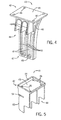
- FIG. 4 is a perspective view of an embodiment of a cast mounting tower 40 (e.g., a one-piece cast metal tower).
- the cast mounting tower 40 may be installed as any one of, or all of, the engine mounting towers 18, 20, or the generator mounting towers 22, 24.
- the cast mounting tower 40 includes an upper mount portion 42 and structural support ribs 44, which support the upper portion 42 and are used to attach the mounting tower 40 to the side-beam 26, 28 of the frame assembly 10. As illustrated, the ribs 44 may extend in a crosswise direction (e.g., perpendicular) from the upper portion 42 of the mounting tower 40.
- the upper portion 42 of the mounting tower 40 may include a mount 45 for direct coupling of the mounting tower 40 to the generator 8 or engine 6.
- the mount 45 (e.g., plate or planar structure) may include holes 46 corresponding to bolts that enable the generator 8 or the engine 6 to be bolted to the mounting tower 40.
- the generator 8 and the engine 6 may also be attached to the mounting tower 40 in other ways as well.
- the mounting tower 40 may be attached by welding, clamping, strapping, male-female joints or fasteners, gluing, bonding, or any other appropriate mount or fastener.
- the ribs 44 of the mounting tower 40 support the upper portion 42 of the mounting tower 40 and are attached to the frame assembly 10.
- the ribs 44 may be attached to the frame assembly 10, via a weld, bolts, clamps, male-female joints, dovetail joints, hook-in-slot joints, or any combination thereof.
- the number of ribs is not limited by the illustrated embodiment. That is, while FIG. 4 illustrates a mounting tower 40 with three ribs 44, other embodiments may include 1, 2, 3, 4, 5, 6, 7, 8, 9, 10, or more ribs 44 to support the upper portion 42 of the mounting tower 40 and attach the mounting tower 40 to the frame assembly 10.
- the ribs 44 are cast together with the upper portion 42 and may be shaped to follow specific contours or shape associated with the frame assembly 10.
- the mounting tower 40 illustrated in FIG. 4 is cast to form a top section 48 and a bottom section 50 of ribs 44.
- the top section 48 of ribs 44 (e.g., upper ribs 48) rest on top of the side-beam 26, 28 onto which the mounting tower 40 is attached.
- the bottom section 50 of ribs 44 (e.g., lower ribs 50) extends past the top of the side-beam 26, 28 and may attach to the bottom of the side-beam 26, 28, may rest on the ground under the side-beam 26, 28, or may rest on the foot plates 34 installed underneath each mounting tower 40.
- the cast construction of the tower 40 creates a one-piece metal structure having all components of the tower 40, including the upper mount portion 42 and structural supports or ribs 44.
- the integral casting of the ribs 44 with the upper mount portion 42 increases rigidity and stiffness, and a vibration damping capability of the tower 42.
- the upper ribs 44, 48 are integrally coupled to the mount portion 42 and an upper mount 45.
- the mount 45 in turn integrally couples with the ribs 44, 50.
- the lower ribs 44, 50 are integrally coupled together to define a framework 47, e.g., ribs 44, 50, mount 45, and lower body 49.
- the framework 47 has a plurality of openings 51 between the ribs 44, 50.
- the openings 51 may interface with corresponding features on the side-beam 26, 28 to which the mounting tower 40 is integrally coupled.
- the interface of the openings 51 may increase rigidity and stiffness of the coupling.
- FIG. 5 is a perspective view of an embodiment of a cast mounting tower 40 having a mounting recess or notch 52 (e.g., female mounting portion).
- the cast mounting tower 40 includes planar ribs 44 that may be shaped to match a corresponding mounting surface on the side-beam 26, 28 to which it is integrally coupled.
- the ribs 44 may include the notch 52 to form around a part of the side-beam 26, 28 of the frame assembly 10.
- the notch 52 as illustrated, may form an elongated slit, such that a plate or other thin part of the side-beam 26, 28 may be installed within the notch 52.
- the notch 52 may have a wider shape, corresponding to a round or square-shaped side-beam 26, 28. More specifically, as explained in detail below, the notch 52 matches the shape of the side-beam 26, 28 to increase security of the connection between the mounting tower 40 and the side-beam 26, 28. Thus, the notch 52 engages the side-beam 26, 28 to form a male-female joint.
- the ribs 44 may include a lower portion 55 that is formed to fit within a corresponding receiving cavity.
- the upper portion 42 may include a rim 54 (e.g., rectangular lip) around the mount 45. The rim 54 may hold resin to better accommodate resin chocking of the mount 45 to the generator 8 or the engine 6.
- the mount 45 may also include mounting holes 46 (e.g., bolt holes) or other appropriate mounts or fasteners.
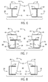
- FIG. 6 is a cross-sectional front end view of an embodiment of a base-frame assembly 10 having I-shaped side beams 26 28.
- the frame assembly 10 includes a cast mounting tower 40 (e.g., one-piece cast metal tower) on each side-beam 26, 28 mounted in an interior side 60 of each side-beam 26, 28. Mounting the cast mounting towers 40 on the interior 60 may be desirable in some instances where the ribs 44 exert an outward force against the frame assembly 10.
- the cast mounting tower 40 includes the notch 52, which extends around top and bottom sides of an upper plate 62 of the I-shaped side beams 26, 28.
- the cast mounting tower 40 may be welded to the upper plate 62 to increase the strength or stiffness of the connection.
- the cast mounting tower 40 illustrated in FIG. 6 illustrates an embodiment of a rigid mounting configuration. This is different from a resilient mounting explained with regard to FIG. 7 .
- FIG. 7 is a cross-sectional front end view of an embodiment of a frame assembly 10 having I-shaped side beams 26, 28.
- the frame assembly 10 includes a cast mounting tower 40 on each side-beam 26, 28 mounted in an exterior side 64 of each side-beam 26, 28. Mounting the mounting towers 40 on the exterior 64 may be desirable in some instances where the ribs 44 exert an inward force against the frame assembly 10.
- the cast mounting tower 40 of FIG. 7 includes the notch 52, which extends around top and bottom sides of an upper plate 62 of the I-shaped side beams 26, 28.
- the mounting tower 40 may be welded to the upper plate 62 to increase the strength or stiffness of the connection.
- the mounting tower 40 includes a cushion 66 (e.g., shock absorber, vibration damper, or resilient material) and a guiding rod 68 between the mount 45 and the generator 8 or the engine 6.
- the cushion 66 damps or softens vibrations and other movement of the generator 8 or the engine 6 during operation.
- the cushion 66 may be integrally coupled to the cast mounting tower 40, or may be cast as part of the one-piece design for the cast mounting tower 40.
- the cushion 66 may be formed as a spring during casting of the cast mounting tower 40.
- the guiding rod 68 fits within a corresponding guide hole to help the generator 8 and/or the engine 6 maintain correct alignment over the mounting tower 40.
- the cast mounting tower 40 includes a bottom male portion 55 that fits within a corresponding cavity 70 that is part of the side-beam 26, 28.
- the cavity 70 may be formed from a band of metal such that it extends around only one of the ribs 44, or may be fabricated to run the entire length of the side-beam 26, 28 thus forming a channel into which all the ribs 4 from all the cast mounting towers 40 are installed.
- the cavity 70 may be deeper or shallower than the illustrated embodiment based on desires for stiffness and security.
- FIG. 8 is a cross-sectional end view of an embodiment of a base-frame assembly having C-shaped side beams 26, 28.
- the mounting tower 40 of FIG. 8 illustrates an embodiment of rigid mounting.
- the mounting towers 40 are installed on the interior 60 side of the frame assembly 10 and the notch 52 receives a portion of each side-beam 26, 28.
- the mounting towers 40 are cast to match the specific characteristics for each location, and the mounting towers 40 may be interchangeably installed for any position below the generator 8, or the engine 6.
- the angle of installation may change with different designs.
- the cast mounting tower 40 may be installed with the notch 52, the mount 45, and the bottom of the cast mounting tower 40 parallel to the ground.
- the cast mounting tower 40 may be installed with a back side 72 of the ribs 44 perpendicular to the ground.
- the notch 52 and the mount 45 etc. may be installed at an angle.
- the mount 45 may be installed at an angle between about 15-90 degrees, 30-60 degrees, 30-45 degrees, or other angles to support the engine-generator set 4.
- a fabricated frame assembly 10 that includes a plurality of mounting towers 11, 18, 20, 22, 24, 40 that are cast as one-piece structures to particular characteristics that match the specifics for each installed location.
- the mounting towers 18, 20, 22, 24, 40 may include an upper portion 42 and a plurality of ribs 44 extending below the upper portion 42 that support the upper portion 42 and attach the mounting tower to the side-beam 26, 28.
- the upper portion 42 and ribs 44 are integrally formed as one-piece, thereby increasing stiffness, rigidity, and reliability of the cast mounting towers 44.
- the cast mounting towers 44 also contribute significantly to the overall stiffness of the frame assembly 10.
Landscapes
- Engineering & Computer Science (AREA)
- General Engineering & Computer Science (AREA)
- Mechanical Engineering (AREA)
- Chemical & Material Sciences (AREA)
- Combustion & Propulsion (AREA)
- Wind Motors (AREA)
- Motor Or Generator Frames (AREA)
Abstract
Description
- The subject matter disclosed herein relates to systems for supporting combustion engines during various operations.
- Combustion engines are used in many land and marine based applications. During overhaul and service (e.g., maintenance, repair, etc.) of the combustion engine, the combustion engine may need to be adjusted, transported, and/or removed from its base frame or location. This removal and/or transportation of the combustion engine may involve transferring the combustion engine between different support frames during the various stages of overhaul, or may involve removing the combustion engine from the support frame to enable ease of access for servicing various components of the engine. In addition, the various connections to the combustion engine may need to be connected and/or disconnected and the combustion engine realigned when reinstalled. All of these factors may increase the time of engine exchange, leading to engine down time that may result in lost revenue.
- Certain embodiments commensurate in scope with the originally claimed invention are summarized below. These embodiments are not intended to limit the scope of the claimed invention, but rather these embodiments are intended only to provide a brief summary of possible forms of the invention. Indeed, the invention may encompass a variety of forms that may be similar to or different from the embodiments set forth below.
- In accordance with a first embodiment, a system includes a cast mounting tower having an upper portion configured to support an engine, a generator, or any combination thereof and a plurality of ribs coupled to and supporting the upper portion of the mounting tower. The plurality of ribs extend from the upper portion in a direction crosswise to the upper portion, the upper portion and the plurality of ribs are integrally coupled as a one-piece structure of the cast mounting tower, and the cast mounting tower is configured to couple to a frame.
- In accordance with a second embodiment, a system includes a support frame and a plurality of cast mounting towers coupled to the support frame. The plurality of cast mounting towers are configured to support an engine-driven generator.
- In accordance with a third embodiment, a method includes casting a plurality of mounting towers for supporting an engine-driven generator. At least one tower of the plurality of mounting towers has an upper portion integrally coupled to a plurality of ribs as a one-piece structure, and the plurality of ribs extend from the upper portion in a crosswise direction relative to the upper portion.
- These and other features, aspects, and advantages of the present invention will become better understood when the following detailed description is read with reference to the accompanying drawings in which like characters represent like parts throughout the drawings, wherein:
-
FIG. 1 is a schematic diagram of an embodiment of a base-frame assembly and engine-generator set; -
FIG. 2 is a perspective view of an embodiment of a base-frame assembly having four engine cast mounting towers and four generator cast mounting towers; -
FIG. 3 is a perspective view of an embodiment of a base-frame assembly having six engine cast mounting towers and four generator cast mounting towers; -
FIG. 4 is a perspective view of an embodiment of a cast mounting tower; -
FIG. 5 is a perspective view of an embodiment of a cast mounting tower having a notch; -
FIG. 6 is a cross-sectional end view of an embodiment of a base-frame assembly having I-shaped side beams; -
FIG. 7 is a cross-sectional end view of an embodiment of a base-frame assembly having C-shaped side beams; and -
FIG. 8 is a cross-sectional end view of an embodiment of a base-frame assembly having I-shaped side beams. - One or more specific embodiments of the present invention will be described below. In an effort to provide a concise description of these embodiments, all features of an actual implementation may not be described in the specification. It should be appreciated that in the development of any such actual implementation, as in any engineering or design project, numerous implementation-specific decisions must be made to achieve the developers' specific goals, such as compliance with system-related and business-related constraints, which may vary from one implementation to another. Moreover, it should be appreciated that such a development effort might be complex and time consuming, but would nevertheless be a routine undertaking of design, fabrication, and manufacture for those of ordinary skill having the benefit of this disclosure.
- When introducing elements of various embodiments of the present invention, the articles "a," "an," "the," and "said" are intended to mean that there are one or more of the elements. The terms "comprising," "including," and "having" are intended to be inclusive and mean that there may be additional elements other than the listed elements.
- As discussed in detail below, the disclosed embodiments include at least partially cast structural support systems for supporting an engine-generator set, such as an electrical generator or gearbox driven by a combustion engine. The combustion engine may include a reciprocating piston engine having a plurality of pistons that reciprocate in respective cylinders. The system include a base that is fabricated from multiple pieces into a support frame assembly suitable for supporting and bearing the weight of the engine, the generator or gearbox, or the combination of both. The fabricated support frame may couple to the engine-generator set in a plurality of ways. One coupling includes mounting towers that attach at a number of points between the support frame assembly and the engine. The mounting towers may include towers that are also fabricated (e.g., welded) from multiple components. In another embodiment, however, the mounting towers may be cast and thus be constructed in one step, for a reduced amount of time and money, while also increasing stiffness. Furthermore, the mounting towers may be designed and assembled to tune the stiffness of the base-frame assembly.
-
FIG. 1 is a schematic diagram of an embodiment of apower generation system 2 having anengine generator set 4, which comprises acombustion engine 6 drivingly coupled to anelectrical generator 8. As discussed in detail below, the engine-generator set 4 is coupled to and supported by a base-frame assembly 10, which includes a plurality of cast mounting towers 11 (e.g., formed as one-piece structures via a metal casting process). - In the illustrated embodiment, the
engine 6 includes a reciprocating internal combustion engine having one ormore combustion chambers 13, each defined by apiston 14 reciprocating in arespective cylinder 15. For example theengine 6 may include 1, 2, 3, 4, 5, 6, 7, 8, 10, 12, 14, 16, 18, 20, 22, 24, 26, ormore combustion chambers 13,pistons 14, andcylinders 15. Anoxidant supply 16 is configured to provide a pressurizedoxidant 16, such as air, oxygen, oxygen-enriched air, oxygen-reduced air, or any combination thereof, to eachcombustion chamber 14. Thecombustion chamber 14 is also configured to receive a fuel 17 (e.g., a liquid and/or gaseous fuel) from afuel supply 17, and a fuel-oxidant mixture ignites and combusts within eachcombustion chamber 13. The hot pressurized combustion gases cause apiston 14 adjacent to eachcombustion chamber 13 to move linearly within thecylinder 15 and convert pressure exerted by the gases into a rotating motion, which causes a shaft to rotate. Further, the shaft may be coupled to a load, e.g., theelectrical generator 8, which is powered via rotation of the shaft. In certain embodiments, thefuel 17 may be any suitable gaseous fuel, such as natural gas, associated petroleum gas, propane, biogas, sewage gas, landfill gas, coal mine gas, for example. Although the illustrated embodiment depicts theengine 6 as a reciprocating internal combustion engine, certain embodiments of theengine 6 may include, for example, a gas turbine engine, a steam turbine engine, a rotary engine, or any other engine able to drive thegenerator 8. - The
system 2 disclosed herein may be adapted for use in stationary applications (e.g., in industrial power generating engines) or in mobile applications (e.g., mobile power distribution unit, such as a semi-truck trailer mountedpower generation system 2, or marine power generation systems 2). Mobile applications may also include embodiments where the power generating engines directly drive the movement (e.g., land or marine based drive trains) The engine 6 (e.g., reciprocating piston engine) may be a two-stroke engine, three-stroke engine, four-stroke engine, five-stroke engine, or six-stroke engine. Theengine 6 may also include any number ofcombustion chambers 13,pistons 14, and associated cylinders 15 (e.g., 1-24). For example, in certain embodiments, thesystem 2 may include a large-scale industrial reciprocating engine having 4, 6, 8, 10, 16, 24 ormore pistons 14 reciprocating incylinders 15. In some such cases, thecylinders 15 and/or thepistons 14 may have a diameter of between approximately 13.5 - 34 centimeters (cm). In some embodiments, thecylinders 15 and/or thepistons 14 may have a diameter of between approximately 10-40 cm, 15-25 cm, or about 15 cm. Thesystem 2 may generate power ranging from 10 kW to 10 MW. In some embodiments, theengine 6 may operate at approximately 1800 revolutions per minute (RPM), particularly forengines 6 powering a grid that operates at 60 Hz. Other embodiments may operate at approximately 1500 RPM, particularly forengines 6 powering a grid that operates at 50 Hz. In some embodiments, theengine 6 may operate at less than approximately 2000 RPM, 1900 RPM, 1800 RPM, 1700 RPM, 1650 RPM, 1500 RPM, 1400 RPM, 1300 RPM, 1200 RPM, 1000 RPM, or 900 RPM. In some embodiments, theengine 6 may operate between approximately 800-2000 RPM, 900-1800 RPM, or 1000-1600 RPM. In some embodiments, theengine 6 may operate at approximately 1800 RPM, 1500 RPM, 1200 RPM, 1000 RPM, or 900 RPM.Exemplary engines 6 may include General Electric Company's Jenbacher Engines (e.g., Jenbacher Type 2, Type 3,Type 4,Type 6 or J920 FleXtra) or Waukesha Engines (e.g., Waukesha VGF, VHP, APG, 275GL), for example. - The
engine 6, as illustrated, is attached to theframe assembly 10 by a plurality of mountingtowers 11, e.g., frontengine mounting towers 18 and back engine mounting towers 20. Likewise, thegenerator 8 is attached to theframe assembly 10 by a plurality of mountingtowers 11, e.g., frontgenerator mounting towers 22 and back generator mounting towers 24. Each of the mountingtowers generator 8 or the engine out of the operating position for service. Furthermore, the mountingtowers towers towers 11 may produce one or more modular towers, which are substantially uniform or identical. The casting of thetowers 11 also may enable casting of multiple (e.g., 2, 3, 4, or more) adjacent towers as a single, one-piece structure. -
FIG. 2 is a perspective view of an embodiment of a base-frame assembly having four enginecast mounting towers 18, 20 (e.g., one-piece cast metal towers) and four generatorcast mounting towers 22, 24 (e.g., one-piece cast metal towers). The frame assembly is fabricated with a right side-beam 26 and a left side-beam 28. The side-beams towers towers frame assembly 10 is supporting.FIG. 2 illustrates that any number ofengine mounting towers beams beams frame assembly 10 may include 2, 3, 4, 5, 6, 8, 10 or moreengine mounting towers generator 8 may be supported by any number ofgenerator mounting towers frame assembly 10 may include 2, 3, 4, 5, 6, 8, 10 or moregenerator mounting towers towers generator 8 or theengine 6 that the mountingtowers towers generator 8 orengine 6. The frame assembly also includes jackingbars 30 andcrossmembers 32 that couple the side-beams frame assembly 10. The jacking bars 30 and thecrossmembers 32 may be fabricated and then subsequently welded or bolted to the side beams 26, 28 to form theframe assembly 10. Theframe assembly 10, as illustrated, includesfoot plates 34 installed underneath each mountingtower tower generator 8 and theengine 6. Thefoot plates 34 may be constructed from metal or elastomeric material to secure the mounting towers 18, 20, 22, 24 and theframe assembly 10 to the ground. That is, thefoot plates 34 may be bolted to the ground to stiffly anchor the mountingtowers -
FIG. 3 is a perspective view of an embodiment of a base-frame assembly 10 having six engine cast engine mounting towers 18, 20 and four generatorcast mounting towers FIG. 3 also illustrates that any number ofengine mounting towers beams beams frame assembly 10 may include 2, 3, 4, 5, 6, 8, 10 or moreengine mounting towers generator 8 may be supported by any number ofgenerator mounting towers frame assembly 10. For example, theframe assembly 10 may include 2, 3, 4, 5, 6, 8, 10 or moregenerator mounting towers generator 8. The mounting towers 22, 24 enable ease of access of thegenerator 8 and ease of removal for service or replacement. - In certain embodiments, two or more of the mounting
towers frame assembly 10. For example, each of the engine mounting towers 18, 20 may be connected together, and/or each of thegenerator mounting towers towers crossmembers 32 and or the jackingbars 30 which may consolidate the multiple pieces into a single assembly. Furthermore, the group may include onecrossmember 32 and/or jackingbar 30 per pair of mountingtowers crossmembers 32 and/or jackingbars 30 per pair of mountingtowers more crossmembers 32 and/or jackingbars 30, or onecrossmember 32 or jackingbar 30 for every two pairs of mountingtowers crossmembers 32/jackingbars 30 may be assembled (i.e., welded together) or, in some embodiments, may be cast together as one piece paragraph about a pair or a couple pairs of towers may be combined with thecrossmembers 32. -
FIG. 4 is a perspective view of an embodiment of a cast mounting tower 40 (e.g., a one-piece cast metal tower). Thecast mounting tower 40 may be installed as any one of, or all of, the engine mounting towers 18, 20, or thegenerator mounting towers cast mounting tower 40 includes anupper mount portion 42 andstructural support ribs 44, which support theupper portion 42 and are used to attach the mountingtower 40 to the side-beam frame assembly 10. As illustrated, theribs 44 may extend in a crosswise direction (e.g., perpendicular) from theupper portion 42 of the mountingtower 40. Theupper portion 42 of the mountingtower 40 may include amount 45 for direct coupling of the mountingtower 40 to thegenerator 8 orengine 6. The mount 45 (e.g., plate or planar structure) may includeholes 46 corresponding to bolts that enable thegenerator 8 or theengine 6 to be bolted to the mountingtower 40. Thegenerator 8 and theengine 6 may also be attached to the mountingtower 40 in other ways as well. For example, the mountingtower 40 may be attached by welding, clamping, strapping, male-female joints or fasteners, gluing, bonding, or any other appropriate mount or fastener. - The
ribs 44 of the mountingtower 40 support theupper portion 42 of the mountingtower 40 and are attached to theframe assembly 10. Theribs 44 may be attached to theframe assembly 10, via a weld, bolts, clamps, male-female joints, dovetail joints, hook-in-slot joints, or any combination thereof. The number of ribs is not limited by the illustrated embodiment. That is, whileFIG. 4 illustrates a mountingtower 40 with threeribs 44, other embodiments may include 1, 2, 3, 4, 5, 6, 7, 8, 9, 10, ormore ribs 44 to support theupper portion 42 of the mountingtower 40 and attach the mountingtower 40 to theframe assembly 10. Theribs 44 are cast together with theupper portion 42 and may be shaped to follow specific contours or shape associated with theframe assembly 10. For example, the mountingtower 40 illustrated inFIG. 4 is cast to form atop section 48 and abottom section 50 ofribs 44. Thetop section 48 of ribs 44 (e.g., upper ribs 48) rest on top of the side-beam tower 40 is attached. Thebottom section 50 of ribs 44 (e.g., lower ribs 50) extends past the top of the side-beam beam beam foot plates 34 installed underneath each mountingtower 40. As appreciated, the cast construction of thetower 40 creates a one-piece metal structure having all components of thetower 40, including theupper mount portion 42 and structural supports orribs 44. The integral casting of theribs 44 with theupper mount portion 42 increases rigidity and stiffness, and a vibration damping capability of thetower 42. As illustrated theupper ribs mount portion 42 and anupper mount 45. Themount 45 in turn integrally couples with theribs lower ribs framework 47, e.g.,ribs mount 45, andlower body 49. Theframework 47 has a plurality ofopenings 51 between theribs openings 51 may interface with corresponding features on the side-beam tower 40 is integrally coupled. The interface of theopenings 51 may increase rigidity and stiffness of the coupling. -
FIG. 5 is a perspective view of an embodiment of acast mounting tower 40 having a mounting recess or notch 52 (e.g., female mounting portion). Thecast mounting tower 40 includesplanar ribs 44 that may be shaped to match a corresponding mounting surface on the side-beam ribs 44 may include thenotch 52 to form around a part of the side-beam frame assembly 10. Thenotch 52, as illustrated, may form an elongated slit, such that a plate or other thin part of the side-beam notch 52. In other embodiments, thenotch 52 may have a wider shape, corresponding to a round or square-shaped side-beam notch 52 matches the shape of the side-beam tower 40 and the side-beam notch 52 engages the side-beam FIG. 7 , theribs 44 may include alower portion 55 that is formed to fit within a corresponding receiving cavity. To augment security between the mountingtower 40 and thegenerator 8 or theengine 6, theupper portion 42, as illustrated, may include a rim 54 (e.g., rectangular lip) around themount 45. Therim 54 may hold resin to better accommodate resin chocking of themount 45 to thegenerator 8 or theengine 6. Themount 45 may also include mounting holes 46 (e.g., bolt holes) or other appropriate mounts or fasteners. -
FIG. 6 is a cross-sectional front end view of an embodiment of a base-frame assembly 10 having I-shaped side beams 26 28. Theframe assembly 10 includes a cast mounting tower 40 (e.g., one-piece cast metal tower) on each side-beam interior side 60 of each side-beam cast mounting towers 40 on the interior 60 may be desirable in some instances where theribs 44 exert an outward force against theframe assembly 10. Also, as illustrated inFIG. 6 , thecast mounting tower 40 includes thenotch 52, which extends around top and bottom sides of anupper plate 62 of the I-shaped side beams 26, 28. Thecast mounting tower 40 may be welded to theupper plate 62 to increase the strength or stiffness of the connection. Thecast mounting tower 40 illustrated inFIG. 6 illustrates an embodiment of a rigid mounting configuration. This is different from a resilient mounting explained with regard toFIG. 7 . -
FIG. 7 is a cross-sectional front end view of an embodiment of aframe assembly 10 having I-shaped side beams 26, 28. Theframe assembly 10 includes acast mounting tower 40 on each side-beam exterior side 64 of each side-beam ribs 44 exert an inward force against theframe assembly 10. Similar to the embodiment illustrated inFIG. 6 , thecast mounting tower 40 ofFIG. 7 includes thenotch 52, which extends around top and bottom sides of anupper plate 62 of the I-shaped side beams 26, 28. The mountingtower 40 may be welded to theupper plate 62 to increase the strength or stiffness of the connection. The mountingtower 40 illustrated inFIG. 7 has an embodiment of a resilient mounting configuration. This is different from the rigid mounting explained with regard toFIG. 6 . For a resilient mounting, the mountingtower 40 includes a cushion 66 (e.g., shock absorber, vibration damper, or resilient material) and a guidingrod 68 between themount 45 and thegenerator 8 or theengine 6. Thecushion 66 damps or softens vibrations and other movement of thegenerator 8 or theengine 6 during operation. Thecushion 66 may be integrally coupled to thecast mounting tower 40, or may be cast as part of the one-piece design for thecast mounting tower 40. For example, thecushion 66 may be formed as a spring during casting of thecast mounting tower 40. In the illustrated embodiment, the guidingrod 68 fits within a corresponding guide hole to help thegenerator 8 and/or theengine 6 maintain correct alignment over the mountingtower 40. - As mentioned above, the
cast mounting tower 40 includes a bottommale portion 55 that fits within a correspondingcavity 70 that is part of the side-beam cavity 70 may be formed from a band of metal such that it extends around only one of theribs 44, or may be fabricated to run the entire length of the side-beam ribs 4 from all thecast mounting towers 40 are installed. Thecavity 70 may be deeper or shallower than the illustrated embodiment based on desires for stiffness and security. -
FIG. 8 is a cross-sectional end view of an embodiment of a base-frame assembly having C-shaped side beams 26, 28. As withFIG. 6 , the mountingtower 40 ofFIG. 8 illustrates an embodiment of rigid mounting. The mounting towers 40 are installed on the interior 60 side of theframe assembly 10 and thenotch 52 receives a portion of each side-beam towers 40 are cast to match the specific characteristics for each location, and the mounting towers 40 may be interchangeably installed for any position below thegenerator 8, or theengine 6. - Furthermore, the angle of installation may change with different designs. For example, as illustrated, the
cast mounting tower 40 may be installed with thenotch 52, themount 45, and the bottom of thecast mounting tower 40 parallel to the ground. In other embodiments, thecast mounting tower 40 may be installed with aback side 72 of theribs 44 perpendicular to the ground. In such an embodiment, thenotch 52 and themount 45 etc. may be installed at an angle. For example, themount 45 may be installed at an angle between about 15-90 degrees, 30-60 degrees, 30-45 degrees, or other angles to support the engine-generator set 4. - Technical effects of the disclosed embodiments include a fabricated
frame assembly 10 that includes a plurality of mountingtowers upper portion 42 and a plurality ofribs 44 extending below theupper portion 42 that support theupper portion 42 and attach the mounting tower to the side-beam upper portion 42 andribs 44 are integrally formed as one-piece, thereby increasing stiffness, rigidity, and reliability of the cast mounting towers 44. Thecast mounting towers 44 also contribute significantly to the overall stiffness of theframe assembly 10. - This written description uses examples to disclose the invention, including the best mode, and also to enable any person skilled in the art to practice the invention, including making and using any devices or systems and performing any incorporated methods. The patentable scope of the invention is defined by the claims, and may include other examples that occur to those skilled in the art. Such other examples are intended to be within the scope of the claims if they have structural elements that do not differ from the literal language of the claims, or if they include equivalent structural elements with insubstantial differences from the literal language of the claims.
- For completeness, various aspects of the invention are set out in the following numbered clauses:
- 1. A system, comprising:
- a cast mounting tower, comprising:
- an upper portion configured to support an engine, a generator, or any combination thereof; and
- a plurality of ribs coupled to and supporting the upper portion of the mounting tower, wherein the plurality of ribs extend from the upper portion in a direction crosswise to the upper portion, the upper portion and the plurality of ribs are integrally coupled as a one-piece structure of the cast mounting tower, and the cast mounting tower is configured to couple to a frame.
- a cast mounting tower, comprising:
- 2. The system of clause 1, comprising the frame having a plurality of interconnected beams.
- 3. The system of clause 1, wherein the plurality of ribs comprises at least three ribs.
- 4. The system of clause 1, comprising a vibration damper disposed along a mount of the upper portion.
- 5. The system of clause 1, wherein the upper portion comprises a first guide configured to interface with a second guide of the engine or the generator.
- 6. The system of clause 1, wherein the cast mounting tower comprises a female joint portion, a male joint portion, or a combination thereof, configured to interface with a respective joint portion of the frame.
- 7. A system, comprising:
- a support frame; and
- a plurality of cast mounting towers coupled to the support frame, wherein the plurality of cast mounting towers are configured to support an engine-driven generator.
- 8. The system of clause 7, wherein the plurality of cast mounting towers comprises a first set of cast mounting towers configured to support the engine and a second set of cast mounting towers configured to support the generator.
- 9. The system of clause 7, wherein the support frame comprises a plurality of I-beams, C-beams, or a combination thereof.
- 10. The system of clause 7, wherein at least one tower of the plurality of cast towers comprises an upper mounting portion integrally coupled to a plurality of ribs as a one-piece structure.
- 11. The system of clause 7, wherein at least one tower of the plurality of cast towers comprises a male joint portion, a female joint portion, or a combination thereof, interfacing with a respective joint portion of the support frame.
- 12. The system of
clause 11, wherein at least one tower comprises the male joint portion disposed between opposite plates of a beam of the support frame. - 13. The system of clause 7, wherein the at least one tower comprises the female joint portion extending about opposite sides of a plate of a beam of the support frame.
- 14. The system of clause 7, comprising the engine and the generator, wherein at least one of the engine or the generator is supported by the plurality of cast mounting towers on the support frame.
- 15. The system of
clause 14, wherein the engine comprises a reciprocating piston engine. - 16. A method, comprising:
- casting a plurality of mounting towers for supporting an engine-driven generator, wherein at least one tower of the plurality of mounting towers comprises an upper portion integrally coupled to a plurality of ribs as a one-piece structure, and the plurality of ribs extend from the upper portion in a crosswise direction relative to the upper portion.
- 17. The method of
clause 16, comprising coupling a vibration damper to at least one tower of the plurality of mounting towers. - 18. The method of
clause 16, comprising coupling the plurality of mounting towers to a support frame assembly. - 19. The method of
clause 18, comprising mounting the engine-driven generator to the support frame, wherein the plurality of mounting towers support the engine, the generator, or a combination thereof. - 20. The method of
clause 18, wherein coupling the plurality of mounting towers to the support frame comprises attaching a female joint portion, a male joint portion, or a combination thereof, to a beam of the support frame.
Claims (15)
- A system, comprising:a cast mounting tower (40), comprising:an upper portion (42) configured to support an engine (6), a generator (8), or any combination thereof; anda plurality of ribs (44) coupled to and supporting the upper portion of the mounting tower (40), wherein the plurality of ribs (44) extend from the upper portion (42) in a direction crosswise to the upper portion, the upper portion (42) and the plurality of ribs (44) are integrally coupled as a one-piece structure of the cast mounting tower, and the cast mounting tower is configured to couple to a frame.
- The system of claim 1, comprising the frame having a plurality of interconnected beams (26,28).
- The system of claim 1, wherein the plurality of ribs (44) comprises at least three ribs.
- The system of claim 1, comprising a vibration damper (66) disposed along a mount of the upper portion.
- The system of claim 1, wherein the upper portion (42) comprises a first guide configured to interface with a second guide of the engine (6) or the generator (8).
- The system of claim 1, wherein the cast mounting tower (40) comprises a female joint portion, a male joint portion, or a combination thereof, configured to interface with a respective joint portion of the frame (10).
- A system, comprising:a support frame (10); anda plurality of cast mounting towers (11) coupled to the support frame (10), wherein the plurality of cast mounting towers (11) are configured to support an engine-driven generator.
- The system of claim 7, wherein the plurality of cast mounting towers (11) comprises a first set of cast mounting towers configured to support the engine (6) and a second set of cast mounting towers configured to support the generator (8).
- The system of claim 7, wherein the support frame (10) comprises a plurality of I-beams, C-beams, or a combination thereof.
- The system of claim 7, wherein at least one tower of the plurality of cast towers (11) comprises an upper mounting portion integrally coupled to a plurality of ribs as a one-piece structure.
- The system of claim 7, wherein at least one tower of the plurality of cast towers (11) comprises a male joint portion, a female joint portion, or a combination thereof, interfacing with a respective joint portion of the support frame.
- The system of claim 11, wherein at least one tower comprises the male joint portion disposed between opposite plates of a beam of the support frame.
- The system of claim 7, wherein the at least one tower comprises the female joint portion extending about opposite sides of a plate of a beam of the support frame.
- The system of claim 7, comprising the engine (6) and the generator (8), wherein at least one of the engine or the generator is supported by the plurality of cast mounting towers (11) on the support frame (10).
- The system of claim 14, wherein the engine comprises a reciprocating piston engine.
Applications Claiming Priority (1)
| Application Number | Priority Date | Filing Date | Title |
|---|---|---|---|
| US14/710,257 US9932893B2 (en) | 2015-05-12 | 2015-05-12 | Base-frame assembly for a combustion engine |
Publications (2)
| Publication Number | Publication Date |
|---|---|
| EP3093547A1 true EP3093547A1 (en) | 2016-11-16 |
| EP3093547B1 EP3093547B1 (en) | 2019-09-18 |
Family
ID=55968953
Family Applications (1)
| Application Number | Title | Priority Date | Filing Date |
|---|---|---|---|
| EP16169002.9A Active EP3093547B1 (en) | 2015-05-12 | 2016-05-10 | Base-frame assembly for a combustion engine |
Country Status (5)
| Country | Link |
|---|---|
| US (1) | US9932893B2 (en) |
| EP (1) | EP3093547B1 (en) |
| JP (1) | JP2016211568A (en) |
| KR (1) | KR20160133365A (en) |
| CN (1) | CN106151784A (en) |
Families Citing this family (6)
| Publication number | Priority date | Publication date | Assignee | Title |
|---|---|---|---|---|
| US10604952B2 (en) * | 2017-08-21 | 2020-03-31 | Sportsfield Intellectual, Llc | Forms for constructing foundations for anchoring pole vault standards |
| US10371012B2 (en) * | 2017-08-29 | 2019-08-06 | On-Power, Inc. | Mobile power generation system including fixture assembly |
| US12280303B2 (en) | 2020-02-14 | 2025-04-22 | Sportsfield Intellectual, Llc | Systems and methods for securing bases, home plates, pitcher's rubbers, and double bases to synthetic turf |
| US11761153B2 (en) | 2020-07-08 | 2023-09-19 | Sportsfield Intellectual, Llc | Forms and methods for constructing a foundation for supporting a home plate |
| KR102292066B1 (en) * | 2021-01-14 | 2021-08-23 | (주)이스트파워 | Earthquake-proof generator capable of conotrolling vibration |
| CN116006826B (en) * | 2023-01-03 | 2024-08-27 | 中国船舶集团有限公司第七一一研究所 | Diesel engine base and diesel engine assembly |
Citations (4)
| Publication number | Priority date | Publication date | Assignee | Title |
|---|---|---|---|---|
| GB415089A (en) * | 1933-01-17 | 1934-08-17 | Doxford William & Sons Ltd | Improvements in welded fabricated structural members |
| US6212749B1 (en) * | 1999-08-30 | 2001-04-10 | General Motors Corporation | Mount assembly system |
| US6439608B1 (en) * | 1999-08-31 | 2002-08-27 | Dana Corporation | Bracket and side rail structure for supporting a steering gear on a vehicle frame assembly |
| US20100194145A1 (en) * | 2008-08-21 | 2010-08-05 | Hiroyuki Akaki | Energy absorbing structure for a vehicle |
Family Cites Families (10)
| Publication number | Priority date | Publication date | Assignee | Title |
|---|---|---|---|---|
| JPS5966091U (en) * | 1982-10-26 | 1984-05-02 | 三和金属工業株式会社 | Engine support stand |
| DE3918283C1 (en) | 1989-06-05 | 1990-05-31 | Audi Ag, 8070 Ingolstadt, De | |
| KR100481504B1 (en) | 2002-11-12 | 2005-04-07 | 삼성전자주식회사 | Controlling apparatus of sampling phase for digital display apparatus and controlling method thereof |
| DE10316029B3 (en) * | 2003-04-07 | 2004-08-05 | Mtu Friedrichshafen Gmbh | Mounting frame for IC engine has engine support mountings spaced by blocks of noise damping material from frame |
| JP5125440B2 (en) * | 2007-11-20 | 2013-01-23 | 日産自動車株式会社 | Power unit support structure |
| JP5354154B2 (en) * | 2008-08-21 | 2013-11-27 | マツダ株式会社 | Automobile frame structure |
| EP2671791B1 (en) * | 2012-06-04 | 2018-07-18 | Caterpillar Motoren GmbH & Co. KG | Damped engine support |
| CN202647077U (en) * | 2012-06-07 | 2013-01-02 | 徐州海虹建筑工程机械有限公司 | Engineering machinery engine support |
| CN203308577U (en) * | 2013-05-09 | 2013-11-27 | 广西玉林卓越动力发电设备有限公司 | Diesel generating set capable of improving installation efficiency and stability in running process |
| CN203656491U (en) * | 2013-12-15 | 2014-06-18 | 河南省电力勘测设计院 | Cold bent stiffening rib equipment support |
-
2015
- 2015-05-12 US US14/710,257 patent/US9932893B2/en not_active Expired - Fee Related
-
2016
- 2016-05-06 JP JP2016092921A patent/JP2016211568A/en active Pending
- 2016-05-10 KR KR1020160056913A patent/KR20160133365A/en not_active Ceased
- 2016-05-10 EP EP16169002.9A patent/EP3093547B1/en active Active
- 2016-05-12 CN CN201610311144.8A patent/CN106151784A/en active Pending
Patent Citations (4)
| Publication number | Priority date | Publication date | Assignee | Title |
|---|---|---|---|---|
| GB415089A (en) * | 1933-01-17 | 1934-08-17 | Doxford William & Sons Ltd | Improvements in welded fabricated structural members |
| US6212749B1 (en) * | 1999-08-30 | 2001-04-10 | General Motors Corporation | Mount assembly system |
| US6439608B1 (en) * | 1999-08-31 | 2002-08-27 | Dana Corporation | Bracket and side rail structure for supporting a steering gear on a vehicle frame assembly |
| US20100194145A1 (en) * | 2008-08-21 | 2010-08-05 | Hiroyuki Akaki | Energy absorbing structure for a vehicle |
Also Published As
| Publication number | Publication date |
|---|---|
| US9932893B2 (en) | 2018-04-03 |
| US20160333777A1 (en) | 2016-11-17 |
| EP3093547B1 (en) | 2019-09-18 |
| JP2016211568A (en) | 2016-12-15 |
| CN106151784A (en) | 2016-11-23 |
| KR20160133365A (en) | 2016-11-22 |
Similar Documents
| Publication | Publication Date | Title |
|---|---|---|
| EP3093547B1 (en) | Base-frame assembly for a combustion engine | |
| JP6639230B2 (en) | Modular gas turbine plant with heavy duty gas turbine | |
| WO2016059468A1 (en) | Multi-point mounting system for rotating machinery | |
| JP2005533984A (en) | Connecting rod device and method | |
| JP2010101318A (en) | System and method for restraining and aligning rotary machinery in longitudinal and lateral directions | |
| CN109154234A (en) | With the generating set installation chassis for reducing gap | |
| CN103508332B (en) | Tower machine and switch base thereof | |
| US10125689B2 (en) | Diffuser removal tool | |
| US10436072B2 (en) | Elastomeric shock absorbers for gas turbine transportation | |
| CN101410649B (en) | Dynamic damper and diesel engine equipped with dynamic damper | |
| CN209329865U (en) | A kind of generating set damping device | |
| US12292415B2 (en) | System and method for load testing a lift beam | |
| EP4098597A1 (en) | System and method for load testing a lift beam | |
| CN215907956U (en) | Connecting structure between gas turbine chassis and foundation | |
| CN111200331B (en) | Generator installation adapter | |
| CN116216061B (en) | Transportation and storage frame for offshore wind power blades | |
| CN104568454B (en) | A kind of turbine test platform peculiar to vessel | |
| GB2525513A (en) | Rotating machine system | |
| WO2007116652A1 (en) | Dynamic damper and diesel engine where dynamic damper is mounted | |
| CN210434838U (en) | Novel environmental protection powerful chevron shape shale shaker | |
| KR101579042B1 (en) | Working platform for assembling turbine | |
| JP2020089257A5 (en) | ||
| RU222182U1 (en) | Reinforced opposed piston compressor frame | |
| RU222174U1 (en) | Reinforced opposed piston compressor frame | |
| CN216807026U (en) | Vibration-damping support leg of adhesive tape machine |
Legal Events
| Date | Code | Title | Description |
|---|---|---|---|
| PUAI | Public reference made under article 153(3) epc to a published international application that has entered the european phase |
Free format text: ORIGINAL CODE: 0009012 |
|
| AK | Designated contracting states |
Kind code of ref document: A1 Designated state(s): AL AT BE BG CH CY CZ DE DK EE ES FI FR GB GR HR HU IE IS IT LI LT LU LV MC MK MT NL NO PL PT RO RS SE SI SK SM TR |
|
| AX | Request for extension of the european patent |
Extension state: BA ME |
|
| STAA | Information on the status of an ep patent application or granted ep patent |
Free format text: STATUS: REQUEST FOR EXAMINATION WAS MADE |
|
| 17P | Request for examination filed |
Effective date: 20170516 |
|
| RBV | Designated contracting states (corrected) |
Designated state(s): AL AT BE BG CH CY CZ DE DK EE ES FI FR GB GR HR HU IE IS IT LI LT LU LV MC MK MT NL NO PL PT RO RS SE SI SK SM TR |
|
| GRAP | Despatch of communication of intention to grant a patent |
Free format text: ORIGINAL CODE: EPIDOSNIGR1 |
|
| STAA | Information on the status of an ep patent application or granted ep patent |
Free format text: STATUS: GRANT OF PATENT IS INTENDED |
|
| INTG | Intention to grant announced |
Effective date: 20190619 |
|
| RAP1 | Party data changed (applicant data changed or rights of an application transferred) |
Owner name: AI ALPINE US BIDCO INC. |
|
| GRAS | Grant fee paid |
Free format text: ORIGINAL CODE: EPIDOSNIGR3 |
|
| GRAA | (expected) grant |
Free format text: ORIGINAL CODE: 0009210 |
|
| STAA | Information on the status of an ep patent application or granted ep patent |
Free format text: STATUS: THE PATENT HAS BEEN GRANTED |
|
| AK | Designated contracting states |
Kind code of ref document: B1 Designated state(s): AL AT BE BG CH CY CZ DE DK EE ES FI FR GB GR HR HU IE IS IT LI LT LU LV MC MK MT NL NO PL PT RO RS SE SI SK SM TR |
|
| REG | Reference to a national code |
Ref country code: GB Ref legal event code: FG4D |
|
| REG | Reference to a national code |
Ref country code: CH Ref legal event code: EP |
|
| REG | Reference to a national code |
Ref country code: DE Ref legal event code: R096 Ref document number: 602016020694 Country of ref document: DE |
|
| REG | Reference to a national code |
Ref country code: AT Ref legal event code: REF Ref document number: 1181746 Country of ref document: AT Kind code of ref document: T Effective date: 20191015 |
|
| REG | Reference to a national code |
Ref country code: IE Ref legal event code: FG4D |
|
| REG | Reference to a national code |
Ref country code: NL Ref legal event code: MP Effective date: 20190918 |
|
| PG25 | Lapsed in a contracting state [announced via postgrant information from national office to epo] |
Ref country code: SE Free format text: LAPSE BECAUSE OF FAILURE TO SUBMIT A TRANSLATION OF THE DESCRIPTION OR TO PAY THE FEE WITHIN THE PRESCRIBED TIME-LIMIT Effective date: 20190918 Ref country code: BG Free format text: LAPSE BECAUSE OF FAILURE TO SUBMIT A TRANSLATION OF THE DESCRIPTION OR TO PAY THE FEE WITHIN THE PRESCRIBED TIME-LIMIT Effective date: 20191218 Ref country code: NO Free format text: LAPSE BECAUSE OF FAILURE TO SUBMIT A TRANSLATION OF THE DESCRIPTION OR TO PAY THE FEE WITHIN THE PRESCRIBED TIME-LIMIT Effective date: 20191218 Ref country code: FI Free format text: LAPSE BECAUSE OF FAILURE TO SUBMIT A TRANSLATION OF THE DESCRIPTION OR TO PAY THE FEE WITHIN THE PRESCRIBED TIME-LIMIT Effective date: 20190918 Ref country code: HR Free format text: LAPSE BECAUSE OF FAILURE TO SUBMIT A TRANSLATION OF THE DESCRIPTION OR TO PAY THE FEE WITHIN THE PRESCRIBED TIME-LIMIT Effective date: 20190918 Ref country code: LT Free format text: LAPSE BECAUSE OF FAILURE TO SUBMIT A TRANSLATION OF THE DESCRIPTION OR TO PAY THE FEE WITHIN THE PRESCRIBED TIME-LIMIT Effective date: 20190918 |
|
| REG | Reference to a national code |
Ref country code: LT Ref legal event code: MG4D |
|
| PG25 | Lapsed in a contracting state [announced via postgrant information from national office to epo] |
Ref country code: AL Free format text: LAPSE BECAUSE OF FAILURE TO SUBMIT A TRANSLATION OF THE DESCRIPTION OR TO PAY THE FEE WITHIN THE PRESCRIBED TIME-LIMIT Effective date: 20190918 Ref country code: LV Free format text: LAPSE BECAUSE OF FAILURE TO SUBMIT A TRANSLATION OF THE DESCRIPTION OR TO PAY THE FEE WITHIN THE PRESCRIBED TIME-LIMIT Effective date: 20190918 Ref country code: GR Free format text: LAPSE BECAUSE OF FAILURE TO SUBMIT A TRANSLATION OF THE DESCRIPTION OR TO PAY THE FEE WITHIN THE PRESCRIBED TIME-LIMIT Effective date: 20191219 Ref country code: RS Free format text: LAPSE BECAUSE OF FAILURE TO SUBMIT A TRANSLATION OF THE DESCRIPTION OR TO PAY THE FEE WITHIN THE PRESCRIBED TIME-LIMIT Effective date: 20190918 |
|
| REG | Reference to a national code |
Ref country code: AT Ref legal event code: MK05 Ref document number: 1181746 Country of ref document: AT Kind code of ref document: T Effective date: 20190918 |
|
| PG25 | Lapsed in a contracting state [announced via postgrant information from national office to epo] |
Ref country code: ES Free format text: LAPSE BECAUSE OF FAILURE TO SUBMIT A TRANSLATION OF THE DESCRIPTION OR TO PAY THE FEE WITHIN THE PRESCRIBED TIME-LIMIT Effective date: 20190918 Ref country code: EE Free format text: LAPSE BECAUSE OF FAILURE TO SUBMIT A TRANSLATION OF THE DESCRIPTION OR TO PAY THE FEE WITHIN THE PRESCRIBED TIME-LIMIT Effective date: 20190918 Ref country code: PL Free format text: LAPSE BECAUSE OF FAILURE TO SUBMIT A TRANSLATION OF THE DESCRIPTION OR TO PAY THE FEE WITHIN THE PRESCRIBED TIME-LIMIT Effective date: 20190918 Ref country code: NL Free format text: LAPSE BECAUSE OF FAILURE TO SUBMIT A TRANSLATION OF THE DESCRIPTION OR TO PAY THE FEE WITHIN THE PRESCRIBED TIME-LIMIT Effective date: 20190918 Ref country code: PT Free format text: LAPSE BECAUSE OF FAILURE TO SUBMIT A TRANSLATION OF THE DESCRIPTION OR TO PAY THE FEE WITHIN THE PRESCRIBED TIME-LIMIT Effective date: 20200120 Ref country code: RO Free format text: LAPSE BECAUSE OF FAILURE TO SUBMIT A TRANSLATION OF THE DESCRIPTION OR TO PAY THE FEE WITHIN THE PRESCRIBED TIME-LIMIT Effective date: 20190918 Ref country code: AT Free format text: LAPSE BECAUSE OF FAILURE TO SUBMIT A TRANSLATION OF THE DESCRIPTION OR TO PAY THE FEE WITHIN THE PRESCRIBED TIME-LIMIT Effective date: 20190918 |
|
| PG25 | Lapsed in a contracting state [announced via postgrant information from national office to epo] |
Ref country code: IS Free format text: LAPSE BECAUSE OF FAILURE TO SUBMIT A TRANSLATION OF THE DESCRIPTION OR TO PAY THE FEE WITHIN THE PRESCRIBED TIME-LIMIT Effective date: 20200224 Ref country code: CZ Free format text: LAPSE BECAUSE OF FAILURE TO SUBMIT A TRANSLATION OF THE DESCRIPTION OR TO PAY THE FEE WITHIN THE PRESCRIBED TIME-LIMIT Effective date: 20190918 Ref country code: SM Free format text: LAPSE BECAUSE OF FAILURE TO SUBMIT A TRANSLATION OF THE DESCRIPTION OR TO PAY THE FEE WITHIN THE PRESCRIBED TIME-LIMIT Effective date: 20190918 Ref country code: SK Free format text: LAPSE BECAUSE OF FAILURE TO SUBMIT A TRANSLATION OF THE DESCRIPTION OR TO PAY THE FEE WITHIN THE PRESCRIBED TIME-LIMIT Effective date: 20190918 |
|
| REG | Reference to a national code |
Ref country code: DE Ref legal event code: R097 Ref document number: 602016020694 Country of ref document: DE |
|
| PLBE | No opposition filed within time limit |
Free format text: ORIGINAL CODE: 0009261 |
|
| STAA | Information on the status of an ep patent application or granted ep patent |
Free format text: STATUS: NO OPPOSITION FILED WITHIN TIME LIMIT |
|
| PG2D | Information on lapse in contracting state deleted |
Ref country code: IS |
|
| PG25 | Lapsed in a contracting state [announced via postgrant information from national office to epo] |
Ref country code: DK Free format text: LAPSE BECAUSE OF FAILURE TO SUBMIT A TRANSLATION OF THE DESCRIPTION OR TO PAY THE FEE WITHIN THE PRESCRIBED TIME-LIMIT Effective date: 20190918 Ref country code: IS Free format text: LAPSE BECAUSE OF FAILURE TO SUBMIT A TRANSLATION OF THE DESCRIPTION OR TO PAY THE FEE WITHIN THE PRESCRIBED TIME-LIMIT Effective date: 20200119 |
|
| PGFP | Annual fee paid to national office [announced via postgrant information from national office to epo] |
Ref country code: DE Payment date: 20200421 Year of fee payment: 5 |
|
| 26N | No opposition filed |
Effective date: 20200619 |
|
| PG25 | Lapsed in a contracting state [announced via postgrant information from national office to epo] |
Ref country code: SI Free format text: LAPSE BECAUSE OF FAILURE TO SUBMIT A TRANSLATION OF THE DESCRIPTION OR TO PAY THE FEE WITHIN THE PRESCRIBED TIME-LIMIT Effective date: 20190918 |
|
| PGFP | Annual fee paid to national office [announced via postgrant information from national office to epo] |
Ref country code: IT Payment date: 20200421 Year of fee payment: 5 |
|
| PG25 | Lapsed in a contracting state [announced via postgrant information from national office to epo] |
Ref country code: CH Free format text: LAPSE BECAUSE OF NON-PAYMENT OF DUE FEES Effective date: 20200531 Ref country code: MC Free format text: LAPSE BECAUSE OF FAILURE TO SUBMIT A TRANSLATION OF THE DESCRIPTION OR TO PAY THE FEE WITHIN THE PRESCRIBED TIME-LIMIT Effective date: 20190918 Ref country code: LI Free format text: LAPSE BECAUSE OF NON-PAYMENT OF DUE FEES Effective date: 20200531 |
|
| REG | Reference to a national code |
Ref country code: BE Ref legal event code: MM Effective date: 20200531 |
|
| GBPC | Gb: european patent ceased through non-payment of renewal fee |
Effective date: 20200510 |
|
| PG25 | Lapsed in a contracting state [announced via postgrant information from national office to epo] |
Ref country code: LU Free format text: LAPSE BECAUSE OF NON-PAYMENT OF DUE FEES Effective date: 20200510 |
|
| PG25 | Lapsed in a contracting state [announced via postgrant information from national office to epo] |
Ref country code: FR Free format text: LAPSE BECAUSE OF NON-PAYMENT OF DUE FEES Effective date: 20200531 Ref country code: IE Free format text: LAPSE BECAUSE OF NON-PAYMENT OF DUE FEES Effective date: 20200510 Ref country code: GB Free format text: LAPSE BECAUSE OF NON-PAYMENT OF DUE FEES Effective date: 20200510 |
|
| PG25 | Lapsed in a contracting state [announced via postgrant information from national office to epo] |
Ref country code: BE Free format text: LAPSE BECAUSE OF NON-PAYMENT OF DUE FEES Effective date: 20200531 |
|
| REG | Reference to a national code |
Ref country code: DE Ref legal event code: R119 Ref document number: 602016020694 Country of ref document: DE |
|
| PG25 | Lapsed in a contracting state [announced via postgrant information from national office to epo] |
Ref country code: DE Free format text: LAPSE BECAUSE OF NON-PAYMENT OF DUE FEES Effective date: 20211201 |
|
| PG25 | Lapsed in a contracting state [announced via postgrant information from national office to epo] |
Ref country code: TR Free format text: LAPSE BECAUSE OF FAILURE TO SUBMIT A TRANSLATION OF THE DESCRIPTION OR TO PAY THE FEE WITHIN THE PRESCRIBED TIME-LIMIT Effective date: 20190918 Ref country code: MT Free format text: LAPSE BECAUSE OF FAILURE TO SUBMIT A TRANSLATION OF THE DESCRIPTION OR TO PAY THE FEE WITHIN THE PRESCRIBED TIME-LIMIT Effective date: 20190918 Ref country code: CY Free format text: LAPSE BECAUSE OF FAILURE TO SUBMIT A TRANSLATION OF THE DESCRIPTION OR TO PAY THE FEE WITHIN THE PRESCRIBED TIME-LIMIT Effective date: 20190918 |
|
| PG25 | Lapsed in a contracting state [announced via postgrant information from national office to epo] |
Ref country code: MK Free format text: LAPSE BECAUSE OF FAILURE TO SUBMIT A TRANSLATION OF THE DESCRIPTION OR TO PAY THE FEE WITHIN THE PRESCRIBED TIME-LIMIT Effective date: 20190918 |
|
| PG25 | Lapsed in a contracting state [announced via postgrant information from national office to epo] |
Ref country code: IT Free format text: LAPSE BECAUSE OF NON-PAYMENT OF DUE FEES Effective date: 20200510 |
|
| P01 | Opt-out of the competence of the unified patent court (upc) registered |
Effective date: 20230602 |
|
| PG25 | Lapsed in a contracting state [announced via postgrant information from national office to epo] |
Ref country code: IT Free format text: LAPSE BECAUSE OF NON-PAYMENT OF DUE FEES Effective date: 20210510 |