EP3093539A1 - Contact signal converter - Google Patents
Contact signal converter Download PDFInfo
- Publication number
- EP3093539A1 EP3093539A1 EP14877965.5A EP14877965A EP3093539A1 EP 3093539 A1 EP3093539 A1 EP 3093539A1 EP 14877965 A EP14877965 A EP 14877965A EP 3093539 A1 EP3093539 A1 EP 3093539A1
- Authority
- EP
- European Patent Office
- Prior art keywords
- voltage
- solenoid
- type electromagnetic
- electromagnetic valve
- batteries
- Prior art date
- Legal status (The legal status is an assumption and is not a legal conclusion. Google has not performed a legal analysis and makes no representation as to the accuracy of the status listed.)
- Granted
Links
Images



Classifications
-
- H—ELECTRICITY
- H02—GENERATION; CONVERSION OR DISTRIBUTION OF ELECTRIC POWER
- H02H—EMERGENCY PROTECTIVE CIRCUIT ARRANGEMENTS
- H02H9/00—Emergency protective circuit arrangements for limiting excess current or voltage without disconnection
- H02H9/04—Emergency protective circuit arrangements for limiting excess current or voltage without disconnection responsive to excess voltage
- H02H9/045—Emergency protective circuit arrangements for limiting excess current or voltage without disconnection responsive to excess voltage adapted to a particular application and not provided for elsewhere
-
- F—MECHANICAL ENGINEERING; LIGHTING; HEATING; WEAPONS; BLASTING
- F16—ENGINEERING ELEMENTS AND UNITS; GENERAL MEASURES FOR PRODUCING AND MAINTAINING EFFECTIVE FUNCTIONING OF MACHINES OR INSTALLATIONS; THERMAL INSULATION IN GENERAL
- F16K—VALVES; TAPS; COCKS; ACTUATING-FLOATS; DEVICES FOR VENTING OR AERATING
- F16K31/00—Actuating devices; Operating means; Releasing devices
- F16K31/02—Actuating devices; Operating means; Releasing devices electric; magnetic
- F16K31/06—Actuating devices; Operating means; Releasing devices electric; magnetic using a magnet, e.g. diaphragm valves, cutting off by means of a liquid
-
- F—MECHANICAL ENGINEERING; LIGHTING; HEATING; WEAPONS; BLASTING
- F16—ENGINEERING ELEMENTS AND UNITS; GENERAL MEASURES FOR PRODUCING AND MAINTAINING EFFECTIVE FUNCTIONING OF MACHINES OR INSTALLATIONS; THERMAL INSULATION IN GENERAL
- F16K—VALVES; TAPS; COCKS; ACTUATING-FLOATS; DEVICES FOR VENTING OR AERATING
- F16K31/00—Actuating devices; Operating means; Releasing devices
- F16K31/02—Actuating devices; Operating means; Releasing devices electric; magnetic
- F16K31/06—Actuating devices; Operating means; Releasing devices electric; magnetic using a magnet, e.g. diaphragm valves, cutting off by means of a liquid
- F16K31/0675—Electromagnet aspects, e.g. electric supply therefor
-
- H—ELECTRICITY
- H01—ELECTRIC ELEMENTS
- H01F—MAGNETS; INDUCTANCES; TRANSFORMERS; SELECTION OF MATERIALS FOR THEIR MAGNETIC PROPERTIES
- H01F7/00—Magnets
- H01F7/06—Electromagnets; Actuators including electromagnets
- H01F7/064—Circuit arrangements for actuating electromagnets
Definitions
- the present invention relates to a contact signal converter configured to convert a contact signal for instructing a valve operation into an electromagnetic valve control signal, and particularly, to a contact signal converter capable of driving a solenoid-type electromagnetic valve.
- a control signal to instruct an opening or closing operation of the valve is sent from a terminal device for operation to a valve driving device.
- communication between the operating device and the valve driving device has been performed by wired communication using a control signal line established between the terminal device and the valve driving device.
- wireless communication is performed in many cases.
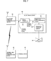
- FIG. 7 depicts a configuration of the terminal device and the valve driving device for performing wireless communication.
- a terminal device 21 for operation is connected with a terminal-side wireless communication device 22, and a valve driving device 60 for opening and closing operations of a valve is connected with a valve-side wireless communication device 23.
- a valve opening contact signal (ON) is wirelessly sent from the terminal-side wireless communication device 22 to the valve-side wireless communication device 23 and is transmitted to the valve driving device 60.
- the valve driving device 60 has a signal converter 61, a piezo-type electromagnetic valve 62 and a pneumatic pressure switch 63.
- the signal converter 61 converts the same into an opening control signal (ON) for operating the piezo-type electromagnetic valve 62 and outputs the converted signal to the piezo-type electromagnetic valve 62.
- the piezo-type electromagnetic valve 62 switches an electromagnetic valve, in response to the opening control signal (ON), the pneumatic pressure switch 63 drives a valve 24 and opens the valve 24.
- an opening contact signal (OFF) is wirelessly sent from the terminal-side wireless communication device 22 to the valve-side wireless communication device 23 and is transmitted to the valve driving device 60.
- the signal converter 61 of the valve driving device 60 converts the valve opening contact signal (OFF) into an opening control signal (OFF) and outputs the same to the piezo-type electromagnetic valve 62.
- the piezo-type electromagnetic valve 62 switches the electromagnetic valve, in response to the opening control signal (OFF), the opening operation of the valve stops.
- Patent Document 1 Japanese Patent Application Publication No. 2003-528269A
- the piezo-type electromagnetic valve 62 is used as the electromagnetic valve.
- the piezo-type electromagnetic valve 62 is not general and has a low degree of selection freedom. Also, since there is no product meeting the intrinsically safe explosion protection specification in Japan, there is a limitation on the using place.
- the solenoid-type electromagnetic valve requires higher power for operation, as compared to the piezo-type electromagnetic valve 62. Specifically, while the piezo-type electromagnetic valve 62 is enabled to operate with 0.003W of 6V and 0.5 mA, the solenoid-type electromagnetic valve requires power 408 mW of DC 12V and 34 mA. For this reason, the piezo-type electromagnetic valve 62 cannot be simply replaced with the solenoid-type electromagnetic valve.
- a contact signal converter configured to convert an on-off contact signal into a control signal for operating a solenoid-type electromagnetic valve.
- the contact signal converter includes an explosion protection barrier configured to restrict a current of the control signal to a maximum current or less established for safety regarding the solenoid-type electromagnetic valve, and a group of batteries, the number of which can ensure a voltage at which a voltage supplied via the explosion protection barrier surpasses an operating voltage of the solenoid-type electromagnetic valve.
- the group of batteries may have the number of batteries by which a maximum open circuit voltage does not surpass the maximum voltage established for safety regarding the solenoid-type electromagnetic valve.
- the group of batteries may have the number of batteries by which a maximum open circuit voltage surpasses the maximum voltage established for safety regarding the solenoid-type electromagnetic valve, and the explosion protection barrier may be further configured to restrict a voltage of the control signal to the maximum voltage or less established for safety regarding the solenoid-type electromagnetic valve.
- the group of batteries has even batteries, and when a number of batteries is smaller than the number of the batteries of the group of batteries by one, the maximum open circuit voltage may not surpass the maximum voltage established for safety regarding the solenoid-type electromagnetic valve.
- the explosion protection barrier is preferably configured to restrict the voltage of the control signal to the maximum voltage or less established for safety regarding the solenoid-type electromagnetic valve by using a Zener diode.
- the explosion protection barrier preferably has a sub-switch configured to be ON or OFF in accordance with the on-off contact signal and arranged at a front stage of the Zener diode.
- a contact signal converter configured to convert an on-off contact signal into a control signal for operating a solenoid-type electromagnetic valve.
- the contact signal converter includes an explosion protection barrier configured to restrict a current of the control signal to a maximum current established for safety regarding the solenoid-type electromagnetic valve and to restrict a voltage of the control signal to a maximum voltage or less established for safety regarding the solenoid-type electromagnetic valve; a battery, and a booster circuit configured to boost an output voltage of the battery so that a voltage to be supplied via the explosion protection barrier becomes a voltage surpassing an operating voltage of the solenoid-type electromagnetic valve.
- the solenoid-type electromagnetic valve in the valve driving device configured to perform wireless communication.
- FIG. 1 is a block diagram depicting a first exemplary embodiment of the present invention.
- a terminal device 21 for operation is connected with a terminal-side wireless communication device 22, and a valve driving device 10 for opening and closing operations of the valve 24 is connected with a valve-side wireless communication device 23.
- the terminal device 21, the terminal-side wireless communication device 22, the valve-side wireless communication device 23 and the valve 24 are the same as the related art. In the below, an opening operation of the valve 24 is exemplified.
- an opening contact signal (ON) is wirelessly sent from the terminal-side wireless communication device 22 to the valve-side wireless communication device 23 and is transmitted to the valve driving device 10.
- an opening contact signal (OFF) is wirelessly sent from the terminal-side wireless communication device 22 to the valve-side wireless communication device 23 and is transmitted to the valve driving device 10.
- the valve driving device 10 has a contact signal converter 110, a solenoid-type electromagnetic valve 120, and a pneumatic pressure switch 130.
- the pneumatic pressure switch 130 is the same as the related art.
- the solenoid-type electromagnetic valve 120 is an electromagnetic valve configured to operate with a voltage, a current and power, which are determined by the specification, and to control opening and closing operations of the pneumatic pressure switch 130.
- the solenoid-type electromagnetic valve 120 preferably meets the intrinsically safe explosion prevention specification.
- DC 12V, 34 mA and 408 mW which are a general voltage value, a current value and a power value.
- the contact signal converter 110 has batteries 111, a current restriction circuit 112, a booster circuit 113, a switch 114 and an explosion protection barrier 115.
- the booster circuit 113 is configured to boost a voltage, which is to be supplied by the batteries 111, to 24V, which is twice as high as an operating voltage (12V) of the solenoid-type electromagnetic valve 120. The reason is that a maximum efficiency of the explosion protection barrier 115 is 50%.
- a general DC-DC converter or the like can be used as the booster circuit 113.
- the switch 114 is a switch that becomes ON or OFF in accordance with an ON or OFF state of the valve opening contact signal transmitted from the valve-side wireless communication device 23.
- a general FET, a transistor or the like can be used as the switch 114.
- the explosion protection barrier 115 is a circuit configured to restrict an output of the booster circuit 113 to an intrinsically safe circuit maximum voltage or less, which is a maximum voltage established for safety regarding the solenoid-type electromagnetic valve 120, and to an intrinsically safe circuit maximum current or less, which is a maximum current established for safety regarding the solenoid-type electromagnetic valve 120.
- the intrinsically safe circuit maximum voltage of the solenoid-type electromagnetic valve 120 is 29.4V, for example, and the intrinsically safe circuit maximum current is 93.8 mA, for example.
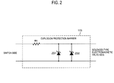
- FIG. 2 is a circuit diagram depicting a configuration example of the explosion protection barrier 115.
- the current is restricted by a resistance R1
- the voltage is restricted to 29.4V or less by Zener diodes ZD1, ZD2.
- the explosion protection barrier 115 may have another circuit configuration.
- the current restriction circuit 112 is a circuit configured to restrict the current flowing from the batteries 111 into the booster circuit 113.
- the current restriction circuit 112 may be configured by a series resistor, for example
- the batteries 111 four batteries for a field device having a general nominal voltage 3.6V (a maximum open circuit voltage 3.9V) are used.
- the maximum efficiency of the current restriction circuit 112 is 50%
- the maximum efficiency of the booster circuit 113 is generally about 80%
- the maximum efficiency of the explosion protection barrier 115 is 50%.
- an output power of the batteries 111 is set to 2 W ( ⁇ 408mW/(0.5 ⁇ 0.8 ⁇ 0.5)) or higher.
- the switch 114 of the contact signal converter 110 becomes ON.
- an opening control signal (ON) is transmitted to the solenoid-type electromagnetic valve 120 via the explosion protection barrier 115.
- the opening control signal is a signal obtained by boosting the output voltage of the batteries 111 with the booster circuit 113.
- a voltage of the opening control signal is a voltage capable of operating the solenoid-type electromagnetic valve 120.
- the solenoid-type electromagnetic valve 120 in the valve driving device 10 configured to perform wireless communication by boosting the output voltage of the batteries 111 with the booster circuit 113.
- the solenoid-type electromagnetic valve 120 is enabled to be used in the valve driving device configured to perform wireless communication by using batteries of which the power feeding capacity is 1.3W or less.
- FIG. 3 is a block diagram depicting the second exemplary embodiment of the present invention.
- the same blocks as the first exemplary embodiment are denoted with the same reference numerals.
- the terminal device 21 for operation is connected with the terminal-side wireless communication device 22
- the valve driving device 11 for opening and closing operations of the valve is connected with the valve-side wireless communication device 23.
- the valve driving device 11 has a contact signal converter 140, the solenoid-type electromagnetic valve 120 and the pneumatic pressure switch 130. Also in the second exemplary embodiment, it is assumed that the solenoid-type electromagnetic valve 120 is configured to operate with DC 12V, 34 mA and 408 mW, which are a general voltage value, a current value and a power value.
- the contact signal converter 140 has batteries 141, an explosion protection barrier 142 and a switch 143.
- the batteries 141 seven batteries for a field device having a general nominal voltage 3.6V (a maximum open circuit voltage 3.9V) are used in series.
- a nominal voltage is 25.2V
- a voltage to be supplied to the solenoid-type electromagnetic valve 120 via the explosion protection barrier 142 having a maximum efficiency 50% is 12.6V
- the supplied voltage surpasses the operating voltage of the solenoid-type electromagnetic valve 120 without using the booster circuit. For this reason, it is not necessary to provide a circuit for restricting the current to flow into the booster circuit, so that it is possible to prevent the efficiency from being lowered.
- the maximum open circuit voltage is 27.3V and does not surpass the intrinsically safe circuit maximum voltage 29.4V of the solenoid-type electromagnetic valve 120. For this reason, it is not necessary to provide the explosion protection barrier 142 with an element for restricting a voltage, for example, a Zener diode. However, when the explosion protection barrier 115 using a Zener diode (refer to FIG. 2 ) is used, batteries of which a maximum open circuit voltage surpasses 29.4V may be used.
- the group of batteries of which the power feeding capacity is 1.3W or less is configured using the seven batteries and the solenoid-type electromagnetic valve 120 is thus enabled to be used in the valve driving device configured to perform wireless communication.
- a battery pack configured to accommodate therein the group of batteries has a specification that the even batteries are generally to be accommodated. Therefore, the configuration of using the odd batteries lacks the general versatility. Therefore, it is considered to use eight batteries.
- the maximum open circuit voltage to be supplied is 31.2V and surpasses the intrinsically safe circuit maximum voltage 29.4V of the solenoid-type electromagnetic valve 120. For this reason, it is necessary to provide the explosion protection barrier with an element for voltage restriction, for example, a Zener diode, as shown in FIG. 2 .
- the Zener diode is always conductive, irrespective of ON and OFF states of the opening contact signal, so that the Zener current continues to flow. For this reason, an amount of consumption of the battery increases, so that the durability of the battery is lowered.
- the solenoid-type electromagnetic valve 120 is enabled to be used in the valve driving device configured to perform wireless communication by using the eight batteries enabling a general battery pack to be used.
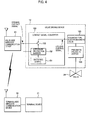
- FIG. 4 is a block diagram depicting the third exemplary embodiment.
- the same blocks as the first exemplary embodiment are denoted with the same reference numerals.
- the terminal device 21 for operation is connected with the terminal-side wireless communication device 22, and the valve driving device 12 for opening and closing operations of the valve is connected with the valve-side wireless communication device 23.
- the valve driving device 12 has a contact signal converter 150, the solenoid-type electromagnetic valve 120 and the pneumatic pressure switch 130. Also in the third exemplary embodiment, it is assumed that the solenoid-type electromagnetic valve 120 is configured to operate with DC 12V, 34 mA and 408 mW, which are a general voltage value, a current value and a power value.
- the contact signal converter 150 has batteries 151, an explosion protection barrier 152 and a switch 153.
- the batteries 151 eight batteries for a field device having a general nominal voltage 3.6V (a maximum open circuit voltage 3.9V) are used in series. Thereby, it is possible to use a general battery pack.
- the opening contact signals are input to the explosion protection barrier 152, in addition to the switch 153.
- FIG. 5 depicts a configuration of the explosion protection barrier 152 in the third exemplary embodiment.
- the explosion protection barrier 152 has not only the resistance R1 for current restriction and the Zener diodes ZD1, ZD2 for voltage restriction but also a sub-switch SW2 provided at a front stage of the Zener diodes ZD1, ZD2 and configured to be switched in accordance with ON and OFF states of the opening contact signal.
- the sub-switch SW2 is switched to OFF when the opening contact signal is OFF. For this reason, the current from the batteries 151 does not flow through the Zener diodes ZD1, ZD2, so that the batteries are not consumed.
- the sub-switch SW2 is switched to ON when the opening contact signal is ON.
- the Zener current is enabled to flow, so that it is possible to restrict the voltage, which is to be applied to the solenoid-type electromagnetic valve 120, to the maximum voltage value or less.
- the explosion protection barrier 152 of the third exemplary embodiment is provided with the sub-switch SW2 at the front stage of the Zener diodes ZD1, ZD2 due to a spaced distance necessary to insulate the battery 151 and the switch 153 therebetween.
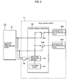
- the opening contact signals which are to be supplied to respective solenoid-type electromagnetic valves 120a, 120b, are input to an OR gate 154, too, and the ON and OFF states of the sub-switch SW2 in the explosion protection barrier 152 are controlled by an output signal of the OR gate 154, as shown in FIG. 6 .
Landscapes
- Engineering & Computer Science (AREA)
- General Engineering & Computer Science (AREA)
- Physics & Mathematics (AREA)
- Electromagnetism (AREA)
- Mechanical Engineering (AREA)
- Power Engineering (AREA)
- Magnetically Actuated Valves (AREA)
- Safety Devices In Control Systems (AREA)
Abstract
Description
- The present invention relates to a contact signal converter configured to convert a contact signal for instructing a valve operation into an electromagnetic valve control signal, and particularly, to a contact signal converter capable of driving a solenoid-type electromagnetic valve.
- When remotely opening or closing a valve in a plant or the like, a control signal to instruct an opening or closing operation of the valve is sent from a terminal device for operation to a valve driving device. In the related art, communication between the operating device and the valve driving device has been performed by wired communication using a control signal line established between the terminal device and the valve driving device. In recent years, however, wireless communication is performed in many cases.
-
FIG. 7 depicts a configuration of the terminal device and the valve driving device for performing wireless communication. As shown inFIG. 7 , aterminal device 21 for operation is connected with a terminal-sidewireless communication device 22, and avalve driving device 60 for opening and closing operations of a valve is connected with a valve-sidewireless communication device 23. - When an operator instructs an opening operation of the
valve driving device 60 by theterminal device 21, a valve opening contact signal (ON) is wirelessly sent from the terminal-sidewireless communication device 22 to the valve-sidewireless communication device 23 and is transmitted to thevalve driving device 60. - The
valve driving device 60 has asignal converter 61, a piezo-typeelectromagnetic valve 62 and apneumatic pressure switch 63. When the opening contact signal (ON) is transmitted from the valve-sidewireless communication device 23, thesignal converter 61 converts the same into an opening control signal (ON) for operating the piezo-typeelectromagnetic valve 62 and outputs the converted signal to the piezo-typeelectromagnetic valve 62. When the piezo-typeelectromagnetic valve 62 switches an electromagnetic valve, in response to the opening control signal (ON), thepneumatic pressure switch 63 drives avalve 24 and opens thevalve 24. - When the operator instructs operation stop of the
valve driving device 60 by theterminal device 21, an opening contact signal (OFF) is wirelessly sent from the terminal-sidewireless communication device 22 to the valve-sidewireless communication device 23 and is transmitted to thevalve driving device 60. Thesignal converter 61 of thevalve driving device 60 converts the valve opening contact signal (OFF) into an opening control signal (OFF) and outputs the same to the piezo-typeelectromagnetic valve 62. When the piezo-typeelectromagnetic valve 62 switches the electromagnetic valve, in response to the opening control signal (OFF), the opening operation of the valve stops. - Patent Document 1: Japanese Patent Application Publication No.
2003-528269A - In the
valve driving device 60 configured to perform wireless communication, the piezo-typeelectromagnetic valve 62 is used as the electromagnetic valve. However, the piezo-typeelectromagnetic valve 62 is not general and has a low degree of selection freedom. Also, since there is no product meeting the intrinsically safe explosion protection specification in Japan, there is a limitation on the using place. - For this reason, it is desired to use a solenoid-type electromagnetic valve that is general, has a high degree of selection freedom and includes a product meeting the intrinsically safe explosion protection specification in Japan.
- However, the solenoid-type electromagnetic valve requires higher power for operation, as compared to the piezo-type
electromagnetic valve 62. Specifically, while the piezo-typeelectromagnetic valve 62 is enabled to operate with 0.003W of 6V and 0.5 mA, the solenoid-type electromagnetic valve requires power 408 mW of DC 12V and 34 mA. For this reason, the piezo-typeelectromagnetic valve 62 cannot be simply replaced with the solenoid-type electromagnetic valve. - It is therefore an object of the present invention to enable use of a solenoid-type electromagnetic valve in a valve driving device configured to perform wireless communication.
- In order to achieve the above object, a contact signal converter according to a first aspect of the present invention is a contact signal converter configured to convert an on-off contact signal into a control signal for operating a solenoid-type electromagnetic valve. The contact signal converter includes an explosion protection barrier configured to restrict a current of the control signal to a maximum current or less established for safety regarding the solenoid-type electromagnetic valve, and a group of batteries, the number of which can ensure a voltage at which a voltage supplied via the explosion protection barrier surpasses an operating voltage of the solenoid-type electromagnetic valve.
- Herein, the group of batteries may have the number of batteries by which a maximum open circuit voltage does not surpass the maximum voltage established for safety regarding the solenoid-type electromagnetic valve.
- Alternatively, the group of batteries may have the number of batteries by which a maximum open circuit voltage surpasses the maximum voltage established for safety regarding the solenoid-type electromagnetic valve, and the explosion protection barrier may be further configured to restrict a voltage of the control signal to the maximum voltage or less established for safety regarding the solenoid-type electromagnetic valve.
- At this time, the group of batteries has even batteries, and when a number of batteries is smaller than the number of the batteries of the group of batteries by one, the maximum open circuit voltage may not surpass the maximum voltage established for safety regarding the solenoid-type electromagnetic valve.
- Also, the explosion protection barrier is preferably configured to restrict the voltage of the control signal to the maximum voltage or less established for safety regarding the solenoid-type electromagnetic valve by using a Zener diode.
- The explosion protection barrier preferably has a sub-switch configured to be ON or OFF in accordance with the on-off contact signal and arranged at a front stage of the Zener diode.
- In order to achieve the above object, a contact signal converter according to a second aspect of the present invention is a contact signal converter configured to convert an on-off contact signal into a control signal for operating a solenoid-type electromagnetic valve. The contact signal converter includes an explosion protection barrier configured to restrict a current of the control signal to a maximum current established for safety regarding the solenoid-type electromagnetic valve and to restrict a voltage of the control signal to a maximum voltage or less established for safety regarding the solenoid-type electromagnetic valve; a battery, and a booster circuit configured to boost an output voltage of the battery so that a voltage to be supplied via the explosion protection barrier becomes a voltage surpassing an operating voltage of the solenoid-type electromagnetic valve.
- According to the present invention, it is possible to use the solenoid-type electromagnetic valve in the valve driving device configured to perform wireless communication.
-
-
FIG. 1 is a block diagram depicting a first exemplary embodiment of the present invention. -
FIG. 2 is a circuit diagram depicting a configuration example of an explosion protection barrier. -
FIG. 3 is a block diagram depicting a second exemplary embodiment of the present invention. -
FIG. 4 is a block diagram depicting a third exemplary embodiment of the present invention. -
FIG. 5 depicts a configuration of an explosion protection barrier in the third exemplary embodiment. -
FIG. 6 is a block diagram depicting a configuration of controlling opening and closing operations of a plurality of solenoid-type electromagnetic valves by a valve-side wireless communication device. -
FIG. 7 depicts a related-art configuration of a terminal device and a valve driving device for performing wireless communication. - Exemplary embodiments of the present invention will be described with reference to the drawings.
FIG. 1 is a block diagram depicting a first exemplary embodiment of the present invention. As shown inFIG. 1 , aterminal device 21 for operation is connected with a terminal-sidewireless communication device 22, and avalve driving device 10 for opening and closing operations of thevalve 24 is connected with a valve-sidewireless communication device 23. Theterminal device 21, the terminal-sidewireless communication device 22, the valve-sidewireless communication device 23 and thevalve 24 are the same as the related art. In the below, an opening operation of thevalve 24 is exemplified. - When an operator instructs an opening operation of a valve by the
terminal device 21, an opening contact signal (ON) is wirelessly sent from the terminal-sidewireless communication device 22 to the valve-sidewireless communication device 23 and is transmitted to thevalve driving device 10. Also, when the operator instructs stop of the valve by theterminal device 21, an opening contact signal (OFF) is wirelessly sent from the terminal-sidewireless communication device 22 to the valve-sidewireless communication device 23 and is transmitted to thevalve driving device 10. - The
valve driving device 10 has acontact signal converter 110, a solenoid-typeelectromagnetic valve 120, and apneumatic pressure switch 130. Thepneumatic pressure switch 130 is the same as the related art. - The solenoid-type
electromagnetic valve 120 is an electromagnetic valve configured to operate with a voltage, a current and power, which are determined by the specification, and to control opening and closing operations of thepneumatic pressure switch 130. The solenoid-typeelectromagnetic valve 120 preferably meets the intrinsically safe explosion prevention specification. Herein, it is assumed that the solenoid-typeelectromagnetic valve 120 is configured to operate with DC 12V, 34 mA and 408 mW, which are a general voltage value, a current value and a power value. - The
contact signal converter 110 hasbatteries 111, acurrent restriction circuit 112, abooster circuit 113, aswitch 114 and anexplosion protection barrier 115. - The
booster circuit 113 is configured to boost a voltage, which is to be supplied by thebatteries 111, to 24V, which is twice as high as an operating voltage (12V) of the solenoid-typeelectromagnetic valve 120. The reason is that a maximum efficiency of theexplosion protection barrier 115 is 50%. As thebooster circuit 113, a general DC-DC converter or the like can be used. - The
switch 114 is a switch that becomes ON or OFF in accordance with an ON or OFF state of the valve opening contact signal transmitted from the valve-sidewireless communication device 23. As theswitch 114, a general FET, a transistor or the like can be used. - The
explosion protection barrier 115 is a circuit configured to restrict an output of thebooster circuit 113 to an intrinsically safe circuit maximum voltage or less, which is a maximum voltage established for safety regarding the solenoid-typeelectromagnetic valve 120, and to an intrinsically safe circuit maximum current or less, which is a maximum current established for safety regarding the solenoid-typeelectromagnetic valve 120. The intrinsically safe circuit maximum voltage of the solenoid-typeelectromagnetic valve 120 is 29.4V, for example, and the intrinsically safe circuit maximum current is 93.8 mA, for example. -
FIG. 2 is a circuit diagram depicting a configuration example of theexplosion protection barrier 115. In the example ofFIG. 2 , the current is restricted by a resistance R1, and the voltage is restricted to 29.4V or less by Zener diodes ZD1, ZD2. Theexplosion protection barrier 115 may have another circuit configuration. - Returning to
FIG. 1 , thecurrent restriction circuit 112 is a circuit configured to restrict the current flowing from thebatteries 111 into thebooster circuit 113. Thecurrent restriction circuit 112 may be configured by a series resistor, for example - As the
batteries 111, four batteries for a field device having a general nominal voltage 3.6V (a maximum open circuit voltage 3.9V) are used. The maximum efficiency of thecurrent restriction circuit 112 is 50%, the maximum efficiency of thebooster circuit 113 is generally about 80%, and the maximum efficiency of theexplosion protection barrier 115 is 50%. For this reason, in order to feed the operating power 408 mW of the solenoid-typeelectromagnetic valve 120, an output power of thebatteries 111 is set to 2 W (≒408mW/(0.5×0.8×0.5)) or higher. - When the valve opening contact signal (ON) is transmitted from the valve-side
wireless communication device 23, theswitch 114 of thecontact signal converter 110 becomes ON. When theswitch 114 becomes ON, an opening control signal (ON) is transmitted to the solenoid-typeelectromagnetic valve 120 via theexplosion protection barrier 115. The opening control signal is a signal obtained by boosting the output voltage of thebatteries 111 with thebooster circuit 113. A voltage of the opening control signal is a voltage capable of operating the solenoid-typeelectromagnetic valve 120. - In this way, according to the first exemplary embodiment, it is possible to use the solenoid-type
electromagnetic valve 120 in thevalve driving device 10 configured to perform wireless communication by boosting the output voltage of thebatteries 111 with thebooster circuit 113. - In the below, a second exemplary embodiment of the present invention is described. In the first exemplary embodiment, in order to feed the operating power of 408 mW to the solenoid-type
electromagnetic valve 120, it is necessary to provide thebatteries 111 having a power feeding capacity of 2W, which is five times or higher. In order to design an intrinsically safe explosion protection structure, it is required to prevent ignition of a combustible gas, which is caused due to heating of a small component when 2W, which is the power feeding capacity of thebatteries 111, is applied to the small component. Also, if a power feeding capacity of a battery can be set to 1.3W or less, a component of which a surface area exceeds 20 mm2 is classified into a temperature class T4. For this reason, if the power feeding capacity of the battery is set to 1.3W or less, it is possible to easily design an intrinsically safe explosion protection structure. - Therefore, in the second exemplary embodiment, the solenoid-type
electromagnetic valve 120 is enabled to be used in the valve driving device configured to perform wireless communication by using batteries of which the power feeding capacity is 1.3W or less. -
FIG. 3 is a block diagram depicting the second exemplary embodiment of the present invention. The same blocks as the first exemplary embodiment are denoted with the same reference numerals. As shown inFIG. 3 , theterminal device 21 for operation is connected with the terminal-sidewireless communication device 22, thevalve driving device 11 for opening and closing operations of the valve is connected with the valve-sidewireless communication device 23. - The
valve driving device 11 has acontact signal converter 140, the solenoid-typeelectromagnetic valve 120 and thepneumatic pressure switch 130. Also in the second exemplary embodiment, it is assumed that the solenoid-typeelectromagnetic valve 120 is configured to operate with DC 12V, 34 mA and 408 mW, which are a general voltage value, a current value and a power value. - The
contact signal converter 140 hasbatteries 141, anexplosion protection barrier 142 and aswitch 143. As thebatteries 141, seven batteries for a field device having a general nominal voltage 3.6V (a maximum open circuit voltage 3.9V) are used in series. When the seven batteries, each of which has a nominal voltage 3.6V, are used in series, a nominal voltage is 25.2V and a voltage to be supplied to the solenoid-typeelectromagnetic valve 120 via theexplosion protection barrier 142 having a maximum efficiency 50% is 12.6V Thereby, the supplied voltage surpasses the operating voltage of the solenoid-typeelectromagnetic valve 120 without using the booster circuit. For this reason, it is not necessary to provide a circuit for restricting the current to flow into the booster circuit, so that it is possible to prevent the efficiency from being lowered. - Also, when the seven batteries are used in series, the maximum open circuit voltage is 27.3V and does not surpass the intrinsically safe circuit maximum voltage 29.4V of the solenoid-type
electromagnetic valve 120. For this reason, it is not necessary to provide theexplosion protection barrier 142 with an element for restricting a voltage, for example, a Zener diode. However, when theexplosion protection barrier 115 using a Zener diode (refer toFIG. 2 ) is used, batteries of which a maximum open circuit voltage surpasses 29.4V may be used. - Since the efficiency of the
explosion protection barrier 142 is 50%, the maximum 50% power of thebatteries 141 can be used for the switching operation of the solenoid-typeelectromagnetic valve 120. For this reason, as the power feeding capacity of thebatteries 141, 816 mW(= 408 mW/0.5) is sufficient. Thereby, it is possible to use the solenoid-typeelectromagnetic valve 120 in the valve driving device configured to perform wireless communication by using the batteries of which the power feeding capacity is 1.3W or less. - In the below, a third exemplary embodiment of the present invention is described. In the second exemplary embodiment, the group of batteries of which the power feeding capacity is 1.3W or less is configured using the seven batteries and the solenoid-type
electromagnetic valve 120 is thus enabled to be used in the valve driving device configured to perform wireless communication. - However, a battery pack configured to accommodate therein the group of batteries has a specification that the even batteries are generally to be accommodated. Therefore, the configuration of using the odd batteries lacks the general versatility. Therefore, it is considered to use eight batteries.
- When the eight batteries, each of which has a nominal voltage 3.6V (the maximum open circuit voltage 3.9V), are used, it is possible to use a versatile battery pack, thereby saving the cost. However, the maximum open circuit voltage to be supplied is 31.2V and surpasses the intrinsically safe circuit maximum voltage 29.4V of the solenoid-type
electromagnetic valve 120. For this reason, it is necessary to provide the explosion protection barrier with an element for voltage restriction, for example, a Zener diode, as shown inFIG. 2 . - In this case, the Zener diode is always conductive, irrespective of ON and OFF states of the opening contact signal, so that the Zener current continues to flow. For this reason, an amount of consumption of the battery increases, so that the durability of the battery is lowered.
- Therefore, in the third exemplary embodiment, the solenoid-type
electromagnetic valve 120 is enabled to be used in the valve driving device configured to perform wireless communication by using the eight batteries enabling a general battery pack to be used. -
FIG. 4 is a block diagram depicting the third exemplary embodiment. The same blocks as the first exemplary embodiment are denoted with the same reference numerals. As shown inFIG. 4 , theterminal device 21 for operation is connected with the terminal-sidewireless communication device 22, and thevalve driving device 12 for opening and closing operations of the valve is connected with the valve-sidewireless communication device 23. - The
valve driving device 12 has acontact signal converter 150, the solenoid-typeelectromagnetic valve 120 and thepneumatic pressure switch 130. Also in the third exemplary embodiment, it is assumed that the solenoid-typeelectromagnetic valve 120 is configured to operate with DC 12V, 34 mA and 408 mW, which are a general voltage value, a current value and a power value. - The
contact signal converter 150 hasbatteries 151, anexplosion protection barrier 152 and aswitch 153. As thebatteries 151, eight batteries for a field device having a general nominal voltage 3.6V (a maximum open circuit voltage 3.9V) are used in series. Thereby, it is possible to use a general battery pack. - In the third exemplary embodiment, the opening contact signals (ON and OFF) are input to the
explosion protection barrier 152, in addition to theswitch 153.FIG. 5 depicts a configuration of theexplosion protection barrier 152 in the third exemplary embodiment. As shown inFIG. 5 , theexplosion protection barrier 152 has not only the resistance R1 for current restriction and the Zener diodes ZD1, ZD2 for voltage restriction but also a sub-switch SW2 provided at a front stage of the Zener diodes ZD1, ZD2 and configured to be switched in accordance with ON and OFF states of the opening contact signal. - The sub-switch SW2 is switched to OFF when the opening contact signal is OFF. For this reason, the current from the
batteries 151 does not flow through the Zener diodes ZD1, ZD2, so that the batteries are not consumed. - On the other hand, the sub-switch SW2 is switched to ON when the opening contact signal is ON. Thereby, the Zener current is enabled to flow, so that it is possible to restrict the voltage, which is to be applied to the solenoid-type
electromagnetic valve 120, to the maximum voltage value or less. - In the meantime, when the Zener diodes are arranged at a rear stage of the
switch 153, the sub-switch is not required. However, theexplosion protection barrier 152 of the third exemplary embodiment is provided with the sub-switch SW2 at the front stage of the Zener diodes ZD1, ZD2 due to a spaced distance necessary to insulate thebattery 151 and theswitch 153 therebetween. - In the below, a configuration where opening and closing operations of a plurality of solenoid-type electromagnetic valves are controlled by the valve-side
wireless communication device 23 is described with reference toFIG. 6 . When controlling the opening and closing operations of the plurality of solenoid-type electromagnetic valves, the opening contact signals, which are to be supplied to respective solenoid-typeelectromagnetic valves OR gate 154, too, and the ON and OFF states of the sub-switch SW2 in theexplosion protection barrier 152 are controlled by an output signal of theOR gate 154, as shown inFIG. 6 . - The above descriptions have been made for the specific exemplary embodiments for the purpose of explaining and illustrating the present invention. Therefore, the present invention is not limited to the above exemplary embodiments and can be variously changed and modified without departing from the gist of the present invention.
- The subject application is based on a Japanese Patent Application No.
2014-000718 filed on January 7, 2014 - 10...valve driving device, 11...valve driving device, 12...valve driving device, 21...terminal device, 22...terminal-side wireless communication device, 23...valve-side wireless communication device, 24...valve, 110...contact signal converter, 111...battery, 112...current restriction circuit, 113...booster circuit, 114...switch, 115...explosion protection barrier, 120...solenoid-type electromagnetic valve, 130...pneumatic pressure switch, 140...contact signal converter, 141...battery, 142...explosion protection barrier, 143...switch, 150...contract signal converter, 151...battery, 152...explosion protection barrier, 153...switch
Claims (7)
- A contact signal converter configured to convert an on-off contact signal into a control signal for operating a solenoid-type electromagnetic valve, the contact signal converter comprising:an explosion protection barrier configured to restrict a current of the control signal to a maximum current or less established for safety regarding the solenoid-type electromagnetic valve; anda group of batteries, the number of which can ensure a voltage at which a voltage supplied via the explosion protection barrier surpasses an operating voltage of the solenoid-type electromagnetic valve.
- The contact signal converter according to claim 1, wherein the group of batteries has the number of batteries by which a maximum open circuit voltage does not surpass the maximum voltage established for safety regarding the solenoid-type electromagnetic valve.
- The contact signal converter according to claim 1, wherein the group of batteries has the number of batteries by which a maximum open circuit voltage surpasses the maximum voltage established for safety regarding the solenoid-type electromagnetic valve, and
wherein the explosion protection barrier is further configured to restrict a voltage of the control signal to the maximum voltage or less established for safety regarding the solenoid-type electromagnetic valve. - The contact signal converter according to claim 3, wherein the group of batteries has even batteries, and
wherein when a number of batteries is smaller than the number of the batteries of the group of batteries by one, the maximum open circuit voltage does not surpass the maximum voltage established for safety regarding the solenoid-type electromagnetic valve. - The contact signal converter according to claim 3 or 4, wherein the explosion protection barrier is configured to restrict the voltage of the control signal to the maximum voltage or less established for safety regarding the solenoid-type electromagnetic valve by using a Zener diode.
- The contact signal converter according to claim 5, wherein the explosion protection barrier has a sub-switch configured to be ON or OFF in accordance with the on-off contact signal and arranged at a front stage of the Zener diode.
- A contact signal converter configured to convert an on-off contact signal into a control signal for operating a solenoid-type electromagnetic valve, the contact signal converter comprising:an explosion protection barrier configured to restrict a current of the control signal to a maximum current established for safety regarding the solenoid-type electromagnetic valve and to restrict a voltage of the control signal to a maximum voltage or less established for safety regarding the solenoid-type electromagnetic valve;a battery, anda booster circuit configured to boost an output voltage of the battery so that a voltage to be supplied via the explosion protection barrier becomes a voltage surpassing an operating voltage of the solenoid-type electromagnetic valve.
Applications Claiming Priority (2)
| Application Number | Priority Date | Filing Date | Title |
|---|---|---|---|
| JP2014000718A JP6007922B2 (en) | 2014-01-07 | 2014-01-07 | Contact signal converter |
| PCT/JP2014/082119 WO2015104926A1 (en) | 2014-01-07 | 2014-12-04 | Contact signal converter |
Publications (3)
| Publication Number | Publication Date |
|---|---|
| EP3093539A1 true EP3093539A1 (en) | 2016-11-16 |
| EP3093539A4 EP3093539A4 (en) | 2017-10-18 |
| EP3093539B1 EP3093539B1 (en) | 2019-05-22 |
Family
ID=53523764
Family Applications (1)
| Application Number | Title | Priority Date | Filing Date |
|---|---|---|---|
| EP14877965.5A Active EP3093539B1 (en) | 2014-01-07 | 2014-12-04 | Contact signal converter |
Country Status (4)
| Country | Link |
|---|---|
| US (1) | US10177565B2 (en) |
| EP (1) | EP3093539B1 (en) |
| JP (1) | JP6007922B2 (en) |
| WO (1) | WO2015104926A1 (en) |
Families Citing this family (8)
| Publication number | Priority date | Publication date | Assignee | Title |
|---|---|---|---|---|
| JP6413344B2 (en) * | 2014-05-22 | 2018-10-31 | 横河電機株式会社 | Explosion-proof barrier in contact signal converter |
| US9958880B2 (en) | 2015-09-16 | 2018-05-01 | Fisher Controls International Llc | Wireless valve actuator system and method |
| JP6260634B2 (en) * | 2016-03-11 | 2018-01-17 | 横河電機株式会社 | Valve opening / closing system, valve control device |
| US10670054B2 (en) * | 2017-10-25 | 2020-06-02 | Dresser, Llc | Constructing valve positioners for hazardous areas |
| US20190168591A1 (en) * | 2017-12-01 | 2019-06-06 | Hyundai Translead | Pneumatic door seal with quick release |
| KR102272465B1 (en) * | 2020-07-13 | 2021-07-05 | 주식회사 썬에이치에스티 | Industrial rechargeable wireless solenoid valve system |
| US20220205313A1 (en) * | 2020-12-30 | 2022-06-30 | Hall Labs Llc | Seal for window covering |
| JP7287413B2 (en) * | 2021-03-26 | 2023-06-06 | 横河電機株式会社 | State detection device |
Family Cites Families (10)
| Publication number | Priority date | Publication date | Assignee | Title |
|---|---|---|---|---|
| JPS51108313A (en) * | 1975-03-20 | 1976-09-25 | Tokico Ltd | KYUYUNOZURU |
| US4038846A (en) * | 1975-10-24 | 1977-08-02 | Paul Klann | Electronic combination lock |
| JPS59165397U (en) * | 1983-04-20 | 1984-11-06 | トキコ株式会社 | Ground-mounted refueling device |
| GB2184260B (en) * | 1985-11-20 | 1989-11-01 | British Gas Plc | Valve operating system |
| US4979067A (en) * | 1989-06-20 | 1990-12-18 | Illinois Tool Works, Inc. | Voltage and current limiting power supply |
| JP3863273B2 (en) * | 1997-12-26 | 2006-12-27 | 富士通株式会社 | Power supply |
| EP1266143B2 (en) | 2000-03-21 | 2010-01-20 | Ross Operating Valve Company | Wireless, intrinsically safe valve |
| US9163619B2 (en) | 2010-09-17 | 2015-10-20 | Safoco, Inc. | Valve actuator control system and method of use |
| US8973595B2 (en) * | 2011-08-01 | 2015-03-10 | Control Microsystems, Inc. | Battery-powered control valve and operation thereof |
| JP5545511B2 (en) | 2012-05-23 | 2014-07-09 | 横河電機株式会社 | Valve remote control device |
-
2014
- 2014-01-07 JP JP2014000718A patent/JP6007922B2/en active Active
- 2014-12-04 US US15/109,929 patent/US10177565B2/en active Active
- 2014-12-04 WO PCT/JP2014/082119 patent/WO2015104926A1/en not_active Ceased
- 2014-12-04 EP EP14877965.5A patent/EP3093539B1/en active Active
Also Published As
| Publication number | Publication date |
|---|---|
| JP6007922B2 (en) | 2016-10-19 |
| EP3093539B1 (en) | 2019-05-22 |
| EP3093539A4 (en) | 2017-10-18 |
| US10177565B2 (en) | 2019-01-08 |
| WO2015104926A1 (en) | 2015-07-16 |
| JP2015129537A (en) | 2015-07-16 |
| US20160336742A1 (en) | 2016-11-17 |
Similar Documents
| Publication | Publication Date | Title |
|---|---|---|
| EP3093539B1 (en) | Contact signal converter | |
| EP2953233B1 (en) | Multiple battery charger and method for controlling the same | |
| EP2293424A3 (en) | AC power switching module | |
| NZ732362A (en) | Electric vehicle power distribution system | |
| WO2007094935A3 (en) | Control of point-of-load regulations and auxiliary devices | |
| TW200618451A (en) | Switching regulator, power supply circuit and secondary cell charging circuit including the same | |
| TW200737070A (en) | Voltage controlled backlight driver | |
| WO2006075652A8 (en) | Semiconductor device for driving led, and led driving device | |
| TW200513010A (en) | An integrating dc-to-dc electric energy converter with dual inputs of high and low voltage sources | |
| CN107172737B (en) | System and method for switched-mode power supply | |
| JP6107591B2 (en) | Vehicle power system | |
| EP3242387A1 (en) | Power control apparatus for sub-module of mmc converter | |
| US20170102751A1 (en) | Tablet computer | |
| CN105874699B (en) | DC-DC Converters | |
| GB201102782D0 (en) | Configurable LED driver/dimmer for solid state lighting applications | |
| US20160049808A1 (en) | Battery charging and discharging of single switch and control method therefor | |
| US20150171753A1 (en) | Switching device | |
| CN108092395B (en) | A backup battery cut-in and float charging control device | |
| KR101306021B1 (en) | Driving device for led lighting operatable using low voltage battery in case of emergency | |
| WO2019080716A1 (en) | Intelligent determination and control circuit of general battery, and lamp | |
| IL180234A (en) | Battery, electrical equipment and a powering method implementing means for short-circuiting the battery | |
| US20130119957A1 (en) | Bi-directional Switching Regulator and Control Circuit Thereof | |
| JP2015222085A (en) | Explosion-proof barrier for contact signal conversion equipment | |
| CN209001918U (en) | A kind of power switch circuit | |
| WO2008122552A3 (en) | Switched-mode power supply with active limiting of the maximum input current |
Legal Events
| Date | Code | Title | Description |
|---|---|---|---|
| PUAI | Public reference made under article 153(3) epc to a published international application that has entered the european phase |
Free format text: ORIGINAL CODE: 0009012 |
|
| 17P | Request for examination filed |
Effective date: 20160705 |
|
| AK | Designated contracting states |
Kind code of ref document: A1 Designated state(s): AL AT BE BG CH CY CZ DE DK EE ES FI FR GB GR HR HU IE IS IT LI LT LU LV MC MK MT NL NO PL PT RO RS SE SI SK SM TR |
|
| AX | Request for extension of the european patent |
Extension state: BA ME |
|
| DAX | Request for extension of the european patent (deleted) | ||
| A4 | Supplementary search report drawn up and despatched |
Effective date: 20170920 |
|
| RIC1 | Information provided on ipc code assigned before grant |
Ipc: G05B 9/02 20060101ALI20170914BHEP Ipc: F16K 31/06 20060101AFI20170914BHEP |
|
| STAA | Information on the status of an ep patent application or granted ep patent |
Free format text: STATUS: EXAMINATION IS IN PROGRESS |
|
| 17Q | First examination report despatched |
Effective date: 20180412 |
|
| GRAP | Despatch of communication of intention to grant a patent |
Free format text: ORIGINAL CODE: EPIDOSNIGR1 |
|
| STAA | Information on the status of an ep patent application or granted ep patent |
Free format text: STATUS: GRANT OF PATENT IS INTENDED |
|
| INTG | Intention to grant announced |
Effective date: 20181204 |
|
| RIN1 | Information on inventor provided before grant (corrected) |
Inventor name: SAITO HITOSHI Inventor name: KANATANI NOBUHIRO |
|
| GRAS | Grant fee paid |
Free format text: ORIGINAL CODE: EPIDOSNIGR3 |
|
| GRAA | (expected) grant |
Free format text: ORIGINAL CODE: 0009210 |
|
| STAA | Information on the status of an ep patent application or granted ep patent |
Free format text: STATUS: THE PATENT HAS BEEN GRANTED |
|
| AK | Designated contracting states |
Kind code of ref document: B1 Designated state(s): AL AT BE BG CH CY CZ DE DK EE ES FI FR GB GR HR HU IE IS IT LI LT LU LV MC MK MT NL NO PL PT RO RS SE SI SK SM TR |
|
| REG | Reference to a national code |
Ref country code: GB Ref legal event code: FG4D |
|
| REG | Reference to a national code |
Ref country code: CH Ref legal event code: EP |
|
| REG | Reference to a national code |
Ref country code: IE Ref legal event code: FG4D |
|
| REG | Reference to a national code |
Ref country code: DE Ref legal event code: R096 Ref document number: 602014047436 Country of ref document: DE |
|
| REG | Reference to a national code |
Ref country code: AT Ref legal event code: REF Ref document number: 1136523 Country of ref document: AT Kind code of ref document: T Effective date: 20190615 |
|
| REG | Reference to a national code |
Ref country code: NL Ref legal event code: MP Effective date: 20190522 |
|
| REG | Reference to a national code |
Ref country code: LT Ref legal event code: MG4D |
|
| PG25 | Lapsed in a contracting state [announced via postgrant information from national office to epo] |
Ref country code: HR Free format text: LAPSE BECAUSE OF FAILURE TO SUBMIT A TRANSLATION OF THE DESCRIPTION OR TO PAY THE FEE WITHIN THE PRESCRIBED TIME-LIMIT Effective date: 20190522 Ref country code: LT Free format text: LAPSE BECAUSE OF FAILURE TO SUBMIT A TRANSLATION OF THE DESCRIPTION OR TO PAY THE FEE WITHIN THE PRESCRIBED TIME-LIMIT Effective date: 20190522 Ref country code: ES Free format text: LAPSE BECAUSE OF FAILURE TO SUBMIT A TRANSLATION OF THE DESCRIPTION OR TO PAY THE FEE WITHIN THE PRESCRIBED TIME-LIMIT Effective date: 20190522 Ref country code: NL Free format text: LAPSE BECAUSE OF FAILURE TO SUBMIT A TRANSLATION OF THE DESCRIPTION OR TO PAY THE FEE WITHIN THE PRESCRIBED TIME-LIMIT Effective date: 20190522 Ref country code: FI Free format text: LAPSE BECAUSE OF FAILURE TO SUBMIT A TRANSLATION OF THE DESCRIPTION OR TO PAY THE FEE WITHIN THE PRESCRIBED TIME-LIMIT Effective date: 20190522 Ref country code: PT Free format text: LAPSE BECAUSE OF FAILURE TO SUBMIT A TRANSLATION OF THE DESCRIPTION OR TO PAY THE FEE WITHIN THE PRESCRIBED TIME-LIMIT Effective date: 20190922 Ref country code: NO Free format text: LAPSE BECAUSE OF FAILURE TO SUBMIT A TRANSLATION OF THE DESCRIPTION OR TO PAY THE FEE WITHIN THE PRESCRIBED TIME-LIMIT Effective date: 20190822 Ref country code: SE Free format text: LAPSE BECAUSE OF FAILURE TO SUBMIT A TRANSLATION OF THE DESCRIPTION OR TO PAY THE FEE WITHIN THE PRESCRIBED TIME-LIMIT Effective date: 20190522 Ref country code: AL Free format text: LAPSE BECAUSE OF FAILURE TO SUBMIT A TRANSLATION OF THE DESCRIPTION OR TO PAY THE FEE WITHIN THE PRESCRIBED TIME-LIMIT Effective date: 20190522 |
|
| PG25 | Lapsed in a contracting state [announced via postgrant information from national office to epo] |
Ref country code: BG Free format text: LAPSE BECAUSE OF FAILURE TO SUBMIT A TRANSLATION OF THE DESCRIPTION OR TO PAY THE FEE WITHIN THE PRESCRIBED TIME-LIMIT Effective date: 20190822 Ref country code: GR Free format text: LAPSE BECAUSE OF FAILURE TO SUBMIT A TRANSLATION OF THE DESCRIPTION OR TO PAY THE FEE WITHIN THE PRESCRIBED TIME-LIMIT Effective date: 20190823 Ref country code: LV Free format text: LAPSE BECAUSE OF FAILURE TO SUBMIT A TRANSLATION OF THE DESCRIPTION OR TO PAY THE FEE WITHIN THE PRESCRIBED TIME-LIMIT Effective date: 20190522 Ref country code: RS Free format text: LAPSE BECAUSE OF FAILURE TO SUBMIT A TRANSLATION OF THE DESCRIPTION OR TO PAY THE FEE WITHIN THE PRESCRIBED TIME-LIMIT Effective date: 20190522 |
|
| REG | Reference to a national code |
Ref country code: AT Ref legal event code: MK05 Ref document number: 1136523 Country of ref document: AT Kind code of ref document: T Effective date: 20190522 |
|
| PG25 | Lapsed in a contracting state [announced via postgrant information from national office to epo] |
Ref country code: EE Free format text: LAPSE BECAUSE OF FAILURE TO SUBMIT A TRANSLATION OF THE DESCRIPTION OR TO PAY THE FEE WITHIN THE PRESCRIBED TIME-LIMIT Effective date: 20190522 Ref country code: SK Free format text: LAPSE BECAUSE OF FAILURE TO SUBMIT A TRANSLATION OF THE DESCRIPTION OR TO PAY THE FEE WITHIN THE PRESCRIBED TIME-LIMIT Effective date: 20190522 Ref country code: CZ Free format text: LAPSE BECAUSE OF FAILURE TO SUBMIT A TRANSLATION OF THE DESCRIPTION OR TO PAY THE FEE WITHIN THE PRESCRIBED TIME-LIMIT Effective date: 20190522 Ref country code: RO Free format text: LAPSE BECAUSE OF FAILURE TO SUBMIT A TRANSLATION OF THE DESCRIPTION OR TO PAY THE FEE WITHIN THE PRESCRIBED TIME-LIMIT Effective date: 20190522 Ref country code: AT Free format text: LAPSE BECAUSE OF FAILURE TO SUBMIT A TRANSLATION OF THE DESCRIPTION OR TO PAY THE FEE WITHIN THE PRESCRIBED TIME-LIMIT Effective date: 20190522 Ref country code: DK Free format text: LAPSE BECAUSE OF FAILURE TO SUBMIT A TRANSLATION OF THE DESCRIPTION OR TO PAY THE FEE WITHIN THE PRESCRIBED TIME-LIMIT Effective date: 20190522 |
|
| REG | Reference to a national code |
Ref country code: DE Ref legal event code: R097 Ref document number: 602014047436 Country of ref document: DE |
|
| PG25 | Lapsed in a contracting state [announced via postgrant information from national office to epo] |
Ref country code: SM Free format text: LAPSE BECAUSE OF FAILURE TO SUBMIT A TRANSLATION OF THE DESCRIPTION OR TO PAY THE FEE WITHIN THE PRESCRIBED TIME-LIMIT Effective date: 20190522 Ref country code: IT Free format text: LAPSE BECAUSE OF FAILURE TO SUBMIT A TRANSLATION OF THE DESCRIPTION OR TO PAY THE FEE WITHIN THE PRESCRIBED TIME-LIMIT Effective date: 20190522 |
|
| PLBE | No opposition filed within time limit |
Free format text: ORIGINAL CODE: 0009261 |
|
| STAA | Information on the status of an ep patent application or granted ep patent |
Free format text: STATUS: NO OPPOSITION FILED WITHIN TIME LIMIT |
|
| PG25 | Lapsed in a contracting state [announced via postgrant information from national office to epo] |
Ref country code: TR Free format text: LAPSE BECAUSE OF FAILURE TO SUBMIT A TRANSLATION OF THE DESCRIPTION OR TO PAY THE FEE WITHIN THE PRESCRIBED TIME-LIMIT Effective date: 20190522 |
|
| 26N | No opposition filed |
Effective date: 20200225 |
|
| PG25 | Lapsed in a contracting state [announced via postgrant information from national office to epo] |
Ref country code: PL Free format text: LAPSE BECAUSE OF FAILURE TO SUBMIT A TRANSLATION OF THE DESCRIPTION OR TO PAY THE FEE WITHIN THE PRESCRIBED TIME-LIMIT Effective date: 20190522 |
|
| PG25 | Lapsed in a contracting state [announced via postgrant information from national office to epo] |
Ref country code: SI Free format text: LAPSE BECAUSE OF FAILURE TO SUBMIT A TRANSLATION OF THE DESCRIPTION OR TO PAY THE FEE WITHIN THE PRESCRIBED TIME-LIMIT Effective date: 20190522 |
|
| REG | Reference to a national code |
Ref country code: CH Ref legal event code: PL |
|
| REG | Reference to a national code |
Ref country code: BE Ref legal event code: MM Effective date: 20191231 |
|
| PG25 | Lapsed in a contracting state [announced via postgrant information from national office to epo] |
Ref country code: MC Free format text: LAPSE BECAUSE OF FAILURE TO SUBMIT A TRANSLATION OF THE DESCRIPTION OR TO PAY THE FEE WITHIN THE PRESCRIBED TIME-LIMIT Effective date: 20190522 |
|
| PG25 | Lapsed in a contracting state [announced via postgrant information from national office to epo] |
Ref country code: LU Free format text: LAPSE BECAUSE OF NON-PAYMENT OF DUE FEES Effective date: 20191204 Ref country code: IE Free format text: LAPSE BECAUSE OF NON-PAYMENT OF DUE FEES Effective date: 20191204 Ref country code: FR Free format text: LAPSE BECAUSE OF NON-PAYMENT OF DUE FEES Effective date: 20191231 |
|
| PG25 | Lapsed in a contracting state [announced via postgrant information from national office to epo] |
Ref country code: LI Free format text: LAPSE BECAUSE OF NON-PAYMENT OF DUE FEES Effective date: 20191231 Ref country code: CH Free format text: LAPSE BECAUSE OF NON-PAYMENT OF DUE FEES Effective date: 20191231 Ref country code: BE Free format text: LAPSE BECAUSE OF NON-PAYMENT OF DUE FEES Effective date: 20191231 |
|
| PG25 | Lapsed in a contracting state [announced via postgrant information from national office to epo] |
Ref country code: CY Free format text: LAPSE BECAUSE OF FAILURE TO SUBMIT A TRANSLATION OF THE DESCRIPTION OR TO PAY THE FEE WITHIN THE PRESCRIBED TIME-LIMIT Effective date: 20190522 |
|
| PG25 | Lapsed in a contracting state [announced via postgrant information from national office to epo] |
Ref country code: IS Free format text: LAPSE BECAUSE OF FAILURE TO SUBMIT A TRANSLATION OF THE DESCRIPTION OR TO PAY THE FEE WITHIN THE PRESCRIBED TIME-LIMIT Effective date: 20190922 |
|
| PG25 | Lapsed in a contracting state [announced via postgrant information from national office to epo] |
Ref country code: MT Free format text: LAPSE BECAUSE OF FAILURE TO SUBMIT A TRANSLATION OF THE DESCRIPTION OR TO PAY THE FEE WITHIN THE PRESCRIBED TIME-LIMIT Effective date: 20190522 Ref country code: HU Free format text: LAPSE BECAUSE OF FAILURE TO SUBMIT A TRANSLATION OF THE DESCRIPTION OR TO PAY THE FEE WITHIN THE PRESCRIBED TIME-LIMIT; INVALID AB INITIO Effective date: 20141204 |
|
| PG25 | Lapsed in a contracting state [announced via postgrant information from national office to epo] |
Ref country code: MK Free format text: LAPSE BECAUSE OF FAILURE TO SUBMIT A TRANSLATION OF THE DESCRIPTION OR TO PAY THE FEE WITHIN THE PRESCRIBED TIME-LIMIT Effective date: 20190522 |
|
| P01 | Opt-out of the competence of the unified patent court (upc) registered |
Effective date: 20230603 |
|
| PGFP | Annual fee paid to national office [announced via postgrant information from national office to epo] |
Ref country code: DE Payment date: 20241121 Year of fee payment: 11 |
|
| PGFP | Annual fee paid to national office [announced via postgrant information from national office to epo] |
Ref country code: GB Payment date: 20241122 Year of fee payment: 11 |