EP3093515A1 - System and method having coupling with layered portion - Google Patents
System and method having coupling with layered portion Download PDFInfo
- Publication number
- EP3093515A1 EP3093515A1 EP16168872.6A EP16168872A EP3093515A1 EP 3093515 A1 EP3093515 A1 EP 3093515A1 EP 16168872 A EP16168872 A EP 16168872A EP 3093515 A1 EP3093515 A1 EP 3093515A1
- Authority
- EP
- European Patent Office
- Prior art keywords
- elastomeric
- portions
- radial
- rotational
- rigid portion
- Prior art date
- Legal status (The legal status is an assumption and is not a legal conclusion. Google has not performed a legal analysis and makes no representation as to the accuracy of the status listed.)
- Withdrawn
Links
- 230000008878 coupling Effects 0.000 title claims abstract description 122
- 238000010168 coupling process Methods 0.000 title claims abstract description 122
- 238000005859 coupling reaction Methods 0.000 title claims abstract description 122
- 238000000034 method Methods 0.000 title claims description 8
- 229920001971 elastomer Polymers 0.000 claims description 64
- 239000013536 elastomeric material Substances 0.000 claims description 25
- 239000000463 material Substances 0.000 claims description 15
- -1 ethylene propylene diene Chemical class 0.000 claims description 7
- 239000004677 Nylon Substances 0.000 claims description 4
- 239000002131 composite material Substances 0.000 claims description 4
- 239000002184 metal Substances 0.000 claims description 4
- 229910052751 metal Inorganic materials 0.000 claims description 4
- 229920001778 nylon Polymers 0.000 claims description 4
- 239000011521 glass Substances 0.000 claims description 3
- 239000005060 rubber Substances 0.000 claims description 3
- 229920001296 polysiloxane Polymers 0.000 claims description 2
- 239000000806 elastomer Substances 0.000 description 61
- 239000012858 resilient material Substances 0.000 description 29
- 238000007906 compression Methods 0.000 description 24
- 238000012546 transfer Methods 0.000 description 22
- 230000006835 compression Effects 0.000 description 17
- 230000035882 stress Effects 0.000 description 15
- 238000002347 injection Methods 0.000 description 12
- 239000007924 injection Substances 0.000 description 12
- 239000000446 fuel Substances 0.000 description 9
- 238000002485 combustion reaction Methods 0.000 description 8
- 238000010248 power generation Methods 0.000 description 8
- 238000010586 diagram Methods 0.000 description 7
- 239000007789 gas Substances 0.000 description 6
- 230000015556 catabolic process Effects 0.000 description 5
- 230000003247 decreasing effect Effects 0.000 description 4
- 238000012423 maintenance Methods 0.000 description 4
- 238000004519 manufacturing process Methods 0.000 description 4
- 239000007800 oxidant agent Substances 0.000 description 4
- 230000001590 oxidative effect Effects 0.000 description 4
- 230000001154 acute effect Effects 0.000 description 3
- QVGXLLKOCUKJST-UHFFFAOYSA-N atomic oxygen Chemical compound [O] QVGXLLKOCUKJST-UHFFFAOYSA-N 0.000 description 3
- 150000001875 compounds Chemical class 0.000 description 3
- 238000006731 degradation reaction Methods 0.000 description 3
- 239000001301 oxygen Substances 0.000 description 3
- 229910052760 oxygen Inorganic materials 0.000 description 3
- 230000008646 thermal stress Effects 0.000 description 3
- 244000043261 Hevea brasiliensis Species 0.000 description 2
- 239000005062 Polybutadiene Substances 0.000 description 2
- ATUOYWHBWRKTHZ-UHFFFAOYSA-N Propane Chemical compound CCC ATUOYWHBWRKTHZ-UHFFFAOYSA-N 0.000 description 2
- 230000008901 benefit Effects 0.000 description 2
- 239000006229 carbon black Substances 0.000 description 2
- 239000000567 combustion gas Substances 0.000 description 2
- 239000004020 conductor Substances 0.000 description 2
- 238000013016 damping Methods 0.000 description 2
- 238000013461 design Methods 0.000 description 2
- 238000011161 development Methods 0.000 description 2
- 230000009977 dual effect Effects 0.000 description 2
- 239000000835 fiber Substances 0.000 description 2
- 239000007788 liquid Substances 0.000 description 2
- 239000011159 matrix material Substances 0.000 description 2
- VNWKTOKETHGBQD-UHFFFAOYSA-N methane Chemical compound C VNWKTOKETHGBQD-UHFFFAOYSA-N 0.000 description 2
- 239000000203 mixture Substances 0.000 description 2
- 229920003052 natural elastomer Polymers 0.000 description 2
- 229920001194 natural rubber Polymers 0.000 description 2
- 230000000704 physical effect Effects 0.000 description 2
- 229920002857 polybutadiene Polymers 0.000 description 2
- 230000002441 reversible effect Effects 0.000 description 2
- 230000035939 shock Effects 0.000 description 2
- 239000000126 substance Substances 0.000 description 2
- 239000004709 Chlorinated polyethylene Substances 0.000 description 1
- 229920000271 Kevlar® Polymers 0.000 description 1
- 229920000459 Nitrile rubber Polymers 0.000 description 1
- CBENFWSGALASAD-UHFFFAOYSA-N Ozone Chemical compound [O-][O+]=O CBENFWSGALASAD-UHFFFAOYSA-N 0.000 description 1
- 239000004952 Polyamide Substances 0.000 description 1
- 239000004698 Polyethylene Substances 0.000 description 1
- 229920002367 Polyisobutene Polymers 0.000 description 1
- 239000004743 Polypropylene Substances 0.000 description 1
- 239000002174 Styrene-butadiene Substances 0.000 description 1
- 229920006311 Urethane elastomer Polymers 0.000 description 1
- 229920000800 acrylic rubber Polymers 0.000 description 1
- 239000003570 air Substances 0.000 description 1
- MTAZNLWOLGHBHU-UHFFFAOYSA-N butadiene-styrene rubber Chemical compound C=CC=C.C=CC1=CC=CC=C1 MTAZNLWOLGHBHU-UHFFFAOYSA-N 0.000 description 1
- 229920005549 butyl rubber Polymers 0.000 description 1
- 238000006243 chemical reaction Methods 0.000 description 1
- YACLQRRMGMJLJV-UHFFFAOYSA-N chloroprene Chemical compound ClC(=C)C=C YACLQRRMGMJLJV-UHFFFAOYSA-N 0.000 description 1
- 239000003245 coal Substances 0.000 description 1
- 230000000295 complement effect Effects 0.000 description 1
- 238000001816 cooling Methods 0.000 description 1
- 239000002283 diesel fuel Substances 0.000 description 1
- 230000000694 effects Effects 0.000 description 1
- 230000005611 electricity Effects 0.000 description 1
- 239000000945 filler Substances 0.000 description 1
- NBVXSUQYWXRMNV-UHFFFAOYSA-N fluoromethane Chemical compound FC NBVXSUQYWXRMNV-UHFFFAOYSA-N 0.000 description 1
- 229920005560 fluorosilicone rubber Polymers 0.000 description 1
- ZZUFCTLCJUWOSV-UHFFFAOYSA-N furosemide Chemical compound C1=C(Cl)C(S(=O)(=O)N)=CC(C(O)=O)=C1NCC1=CC=CO1 ZZUFCTLCJUWOSV-UHFFFAOYSA-N 0.000 description 1
- 239000003502 gasoline Substances 0.000 description 1
- 238000001746 injection moulding Methods 0.000 description 1
- 239000004761 kevlar Substances 0.000 description 1
- 229910001092 metal group alloy Inorganic materials 0.000 description 1
- 150000002739 metals Chemical class 0.000 description 1
- 230000000116 mitigating effect Effects 0.000 description 1
- 238000002156 mixing Methods 0.000 description 1
- 239000003345 natural gas Substances 0.000 description 1
- 239000012811 non-conductive material Substances 0.000 description 1
- 239000002245 particle Substances 0.000 description 1
- 239000003209 petroleum derivative Substances 0.000 description 1
- 229920003229 poly(methyl methacrylate) Polymers 0.000 description 1
- 229920000058 polyacrylate Polymers 0.000 description 1
- 229920002647 polyamide Polymers 0.000 description 1
- 229920000573 polyethylene Polymers 0.000 description 1
- 229920001195 polyisoprene Polymers 0.000 description 1
- 229920000642 polymer Polymers 0.000 description 1
- 239000004926 polymethyl methacrylate Substances 0.000 description 1
- 229920001155 polypropylene Polymers 0.000 description 1
- 229920002635 polyurethane Polymers 0.000 description 1
- 239000004814 polyurethane Substances 0.000 description 1
- 229920002689 polyvinyl acetate Polymers 0.000 description 1
- 239000011118 polyvinyl acetate Substances 0.000 description 1
- 229920000915 polyvinyl chloride Polymers 0.000 description 1
- 239000004800 polyvinyl chloride Substances 0.000 description 1
- 239000001294 propane Substances 0.000 description 1
- 238000005086 pumping Methods 0.000 description 1
- 239000011208 reinforced composite material Substances 0.000 description 1
- 239000012779 reinforcing material Substances 0.000 description 1
- 239000010865 sewage Substances 0.000 description 1
- 229920002379 silicone rubber Polymers 0.000 description 1
- 239000004945 silicone rubber Substances 0.000 description 1
- 239000011115 styrene butadiene Substances 0.000 description 1
- 229920003048 styrene butadiene rubber Polymers 0.000 description 1
Images





Classifications
-
- F—MECHANICAL ENGINEERING; LIGHTING; HEATING; WEAPONS; BLASTING
- F16—ENGINEERING ELEMENTS AND UNITS; GENERAL MEASURES FOR PRODUCING AND MAINTAINING EFFECTIVE FUNCTIONING OF MACHINES OR INSTALLATIONS; THERMAL INSULATION IN GENERAL
- F16D—COUPLINGS FOR TRANSMITTING ROTATION; CLUTCHES; BRAKES
- F16D3/00—Yielding couplings, i.e. with means permitting movement between the connected parts during the drive
- F16D3/02—Yielding couplings, i.e. with means permitting movement between the connected parts during the drive adapted to specific functions
-
- F—MECHANICAL ENGINEERING; LIGHTING; HEATING; WEAPONS; BLASTING
- F16—ENGINEERING ELEMENTS AND UNITS; GENERAL MEASURES FOR PRODUCING AND MAINTAINING EFFECTIVE FUNCTIONING OF MACHINES OR INSTALLATIONS; THERMAL INSULATION IN GENERAL
- F16D—COUPLINGS FOR TRANSMITTING ROTATION; CLUTCHES; BRAKES
- F16D3/00—Yielding couplings, i.e. with means permitting movement between the connected parts during the drive
- F16D3/50—Yielding couplings, i.e. with means permitting movement between the connected parts during the drive with the coupling parts connected by one or more intermediate members
- F16D3/76—Yielding couplings, i.e. with means permitting movement between the connected parts during the drive with the coupling parts connected by one or more intermediate members shaped as an elastic ring centered on the axis, surrounding a portion of one coupling part and surrounded by a sleeve of the other coupling part
-
- B—PERFORMING OPERATIONS; TRANSPORTING
- B32—LAYERED PRODUCTS
- B32B—LAYERED PRODUCTS, i.e. PRODUCTS BUILT-UP OF STRATA OF FLAT OR NON-FLAT, e.g. CELLULAR OR HONEYCOMB, FORM
- B32B1/00—Layered products having a non-planar shape
- B32B1/08—Tubular products
-
- B—PERFORMING OPERATIONS; TRANSPORTING
- B32—LAYERED PRODUCTS
- B32B—LAYERED PRODUCTS, i.e. PRODUCTS BUILT-UP OF STRATA OF FLAT OR NON-FLAT, e.g. CELLULAR OR HONEYCOMB, FORM
- B32B15/00—Layered products comprising a layer of metal
- B32B15/04—Layered products comprising a layer of metal comprising metal as the main or only constituent of a layer, which is next to another layer of the same or of a different material
- B32B15/06—Layered products comprising a layer of metal comprising metal as the main or only constituent of a layer, which is next to another layer of the same or of a different material of natural rubber or synthetic rubber
-
- F—MECHANICAL ENGINEERING; LIGHTING; HEATING; WEAPONS; BLASTING
- F16—ENGINEERING ELEMENTS AND UNITS; GENERAL MEASURES FOR PRODUCING AND MAINTAINING EFFECTIVE FUNCTIONING OF MACHINES OR INSTALLATIONS; THERMAL INSULATION IN GENERAL
- F16D—COUPLINGS FOR TRANSMITTING ROTATION; CLUTCHES; BRAKES
- F16D3/00—Yielding couplings, i.e. with means permitting movement between the connected parts during the drive
- F16D3/02—Yielding couplings, i.e. with means permitting movement between the connected parts during the drive adapted to specific functions
- F16D3/12—Yielding couplings, i.e. with means permitting movement between the connected parts during the drive adapted to specific functions specially adapted for accumulation of energy to absorb shocks or vibration
-
- F—MECHANICAL ENGINEERING; LIGHTING; HEATING; WEAPONS; BLASTING
- F16—ENGINEERING ELEMENTS AND UNITS; GENERAL MEASURES FOR PRODUCING AND MAINTAINING EFFECTIVE FUNCTIONING OF MACHINES OR INSTALLATIONS; THERMAL INSULATION IN GENERAL
- F16D—COUPLINGS FOR TRANSMITTING ROTATION; CLUTCHES; BRAKES
- F16D3/00—Yielding couplings, i.e. with means permitting movement between the connected parts during the drive
- F16D3/02—Yielding couplings, i.e. with means permitting movement between the connected parts during the drive adapted to specific functions
- F16D3/14—Yielding couplings, i.e. with means permitting movement between the connected parts during the drive adapted to specific functions combined with a friction coupling for damping vibration or absorbing shock
-
- F—MECHANICAL ENGINEERING; LIGHTING; HEATING; WEAPONS; BLASTING
- F16—ENGINEERING ELEMENTS AND UNITS; GENERAL MEASURES FOR PRODUCING AND MAINTAINING EFFECTIVE FUNCTIONING OF MACHINES OR INSTALLATIONS; THERMAL INSULATION IN GENERAL
- F16F—SPRINGS; SHOCK-ABSORBERS; MEANS FOR DAMPING VIBRATION
- F16F1/00—Springs
- F16F1/36—Springs made of rubber or other material having high internal friction, e.g. thermoplastic elastomers
- F16F1/38—Springs made of rubber or other material having high internal friction, e.g. thermoplastic elastomers with a sleeve of elastic material between a rigid outer sleeve and a rigid inner sleeve or pin, i.e. bushing-type
- F16F1/387—Springs made of rubber or other material having high internal friction, e.g. thermoplastic elastomers with a sleeve of elastic material between a rigid outer sleeve and a rigid inner sleeve or pin, i.e. bushing-type comprising means for modifying the rigidity in particular directions
- F16F1/3876—Springs made of rubber or other material having high internal friction, e.g. thermoplastic elastomers with a sleeve of elastic material between a rigid outer sleeve and a rigid inner sleeve or pin, i.e. bushing-type comprising means for modifying the rigidity in particular directions by means of inserts of more rigid material
-
- F—MECHANICAL ENGINEERING; LIGHTING; HEATING; WEAPONS; BLASTING
- F16—ENGINEERING ELEMENTS AND UNITS; GENERAL MEASURES FOR PRODUCING AND MAINTAINING EFFECTIVE FUNCTIONING OF MACHINES OR INSTALLATIONS; THERMAL INSULATION IN GENERAL
- F16D—COUPLINGS FOR TRANSMITTING ROTATION; CLUTCHES; BRAKES
- F16D2250/00—Manufacturing; Assembly
Definitions
- the subject matter disclosed herein relates to a mechanical coupling, and, more particularly to a rotational coupling to transfer torque between machinery.
- a rotational coupling may be used to transfer torque between a variety of machinery, such as an engine and a load.
- a power generation system may include an engine (e.g., reciprocating engine or gas turbine) drivingly coupled to an electric generator.
- the power generation system may produce between 100kW and 10MW or more of electricity.
- the rotational coupling may be susceptible to wear and/or degradation due to torque, vibration, shock, misalignment, thermal stress, and/or mechanical stress.
- a system in a first embodiment, includes a rotational coupling including a first rotational joint, a second rotational joint, and a coupling body disposed between the first and second rotational joints.
- the coupling body includes first and second body portions disposed about a rotational axis, and a layered portion disposed about the rotational axis radially between the first and second body portions.
- the layered portion includes first and second elastomeric portions disposed about the rotational axis, and a rigid portion disposed about the rotational axis radially between the first and second elastomeric portions.
- the rigid portion includes a plurality of radial protrusions.
- a system in a second embodiment, includes a coupling including a central axis, an inner body portion disposed about the central axis, an outer body portion disposed about the inner body portion, and a layered portion disposed about the central axis radially between the inner and outer body portions.
- the layered portion includes inner and outer elastomeric portions disposed about the central axis, and a rigid portion disposed about the central axis radially between the inner and outer elastomeric portions.
- the rigid portion includes a plurality of radial protrusions interfacing with the outer elastomeric portion.
- a method in a third embodiment, includes transferring torque through a layered portion of a rotational coupling between first and second machines.
- the layered portion includes first and second elastomeric portions disposed about a rotational axis, and a rigid portion disposed about the rotational axis radially between the first and second elastomeric portions.
- the rigid portion includes a plurality of radial protrusions.
- the present disclosure relates to flexible couplings for transmitting torque between machinery, such as shafts of dual shaft power generation systems (e.g., engine-generator sets).
- the flexible coupling may connect an engine shaft with a corresponding load shaft of a generator or gearbox.
- the flexible coupling includes a layered portion having a plurality of resilient portions (e.g., resilient material) disposed about a rigid portion (e.g., rigid material).
- the layered portion may help to improve shaft alignment, damp vibration, absorb shock (e.g., due to sudden changes in torque and/or reversal in torque), reduce thermal stress, and reduce mechanical stress, while also transferring torque between machinery (e.g., engine to generator, or gearbox).
- the resilient material may accommodate shaft misalignment, in particular, in engine-generator sets that include at least one resiliently mounted engine and/or generator, or gearbox.
- the resilient material in the flexible coupling may provide a cushion for vibrations associated with operation of the system, thereby damping the vibrations and mitigating noise, and not limited to engine-generator sets that include at least one resiliently mounted engine, generator, or gearbox and also applicable to rigidly mounted engine and rigidly mounted driven article.
- Various types of couplings may incorporate a resilient material to transfer torque from one rotating shaft to an adjacent shaft.
- flexible in-shear couplings such as toothed type couplings and low radial/high flexibility couplings, transfer torque via shear forces.
- Other flexible couplings include flexible in-compression couplings, which transfer torque via compression forces. Properties of the resilient material in the flexible couplings may depend on the manner in which the flexible couplings transfers the torque (e.g., via compression or shear).
- the resilient material used for flexible in-compression couplings may have a higher degree of torsional stiffness compared to the resilient material used for flexible in-shear couplings (e.g., elastomer in-shear couplings), which generally have a higher degree of torsional softness.
- the resilient material in the flexible in-shear couplings stretches and twists during torque transfer. The stretching and twisting of the resilient material may result in areas of high stress load that may decrease the overall durability of the resilient material in the flexible in-shear couplings compared to the flexible in-compression couplings.
- the high stress load in combination with elevated system temperatures, may cause the resilient material to wear and breakdown (e.g., degrade), thereby decreasing system performance and reliability.
- flexible in-shear couplings may be replaced more frequently compared to flexible in-compression couplings, increasing equipment and maintenance costs, e.g., for dual shaft power generation systems that use flexible in-shear couplings for torque transfer.
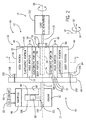
- FIG. 1 illustrates a block diagram of a system 10 having first and second machines 12 and 14 coupled together with a rotational coupling 16 (e.g., resilient or flexible rotational coupling), wherein the rotational coupling 16 includes a coupling body 18 having a layered portion 20 with a plurality of layers 22 of alternating resilient and rigid materials in a sandwich arrangement (e.g., concentric layers).
- the rotational coupling 16 may improve system durability, operability, and reliability by loading certain regions of the resilient material in compression, rather than in shear. As shown in FIG.
- the rotational coupling 16 includes first and second rotational joints 24 and 26 coupled to respective shafts 13 and 15 of the first and second machines 12 and 14 to facilitate rotation about a rotational axis 28 (e.g., transfer power and torque).
- the first machine 12 provides power and/or transfers torque to drive the second machine 14, and thus the first machine 12 may include an engine or driving machine while the second machine 14 may include a load or driven machine.
- the second machine 14 provides power and/or transfers torque to drive the first machine 12, and thus the second machine 14 may include an engine or driving machine while the first machine 12 may include a load or driven machine.
- the engine or driving machine may include, but is not limited to, a gas turbine, a steam turbine, a wind turbine, a hydro turbine, a reciprocating engine (discussed in detail below with reference to FIG. 2 ), an electric motor, or any combination thereof.
- the load or driven machine (e.g., 12 or 14) may include, but is not limited to, a vehicle or a stationary load.
- the load or driven machine may include an electrical generator of a power generation system 10, a compressor, a pump, an industrial machine or automation system, a drivetrain of a vehicle, a propeller of an aircraft or watercraft, or any suitable device capable of being powered by the rotational output of the engine or driving machine.
- the rotational coupling 16 links (e.g., connects) the shafts 13, 15 and transmits torque from the first shaft 13 to the second shaft 15 or vice versa, depending on which machines 12, 14 are driving and driven.
- the first rotational joint 24 on a first side 36 of the rotational coupling 16 has a first hub 40 (e.g. a flywheel), while the second rotational joint 26 on a second side 42 has a second hub 46 (e.g., a flywheel).
- the first and second hubs 40, 46 may be driving and driven hubs or vice versa, depending on which machines 12, 14 are driving and driven.
- the first and second hubs 40, 46 are coupled to different body portions of the coupling body 18, such that the layered portion 20 with layers 22 is disposed between and thus transfers torque between the hubs 40, 46.
- the rotational coupling 16 includes an outer body portion 48 (e.g., annular body portion) that couples to the hub 40, and an inner body portion 50 (e.g., annular or cylindrical body portion) that couples to the hub 46.
- the outer body portion 48 is disposed circumferentially 34 about the layered portion 20, the inner body portion 50 and at least a portion of the hub 46, the second shaft 15, or a combination thereof (e.g., in a coaxial or concentric arrangement).
- the inner body portion 50 is disposed circumferentially 34 about at least a portion of the hub 46, the second shaft 15, or a combination thereof (e.g., in a coaxial or concentric arrangement).
- the layered portion 20 with layers 22 is disposed radially 32 between the body portions 48, 50, such that the layered portion 20 is sandwiched between (and separates) the body portions 48, 50.
- the body portions 48, 50 do not directly couple to one another, and thus torque is not transferred directly between the body portions 48, 50. Instead, the torque transfers to one of the body portions (e.g., 48 or 50), through the layers 22 in the layered portion 20, and subsequently through the other of the body portions (e.g., 48 or 50), thereby enabling torque transfer between the machines 12, 14.
- the rotational joints 24 and 26 may include a variety of couplings, such as threaded fasteners, male-female joints, clamps, flanges, interference fits, or any combination thereof.
- the rotational joint 24 at the outer body portion 48 may include a plurality of fasteners 52 (e.g., threaded fasteners) securing the hub 40 to the outer body portion 48.
- the rotational joint 26 at the inner body portion 50 may include the hub 46 and an opening 54 (e.g., annular opening) that accommodates at least a portion of the hub 46 and/or the second shaft 15.
- the annular opening 54 may have a radial dimension 58 that is greater than or equal to a shaft dimension 60.
- the rotational joint 26 may include an internal joint 56 within the opening 54, thereby internally securing the shaft 15 and/or the hub 46 within the opening 54 of the inner body portion 50.
- the internal joint 56 may include a male-female joint, such as a key in slot joint, a spline joint, or any combination thereof.
- the rotational joint 26 may include a plurality of fasteners 52 (e.g., threaded fasteners or bolts) securing the shaft 15 and/or the hub 46 to the inner body portion 50.
- torque may be transferred through the first rotational joint 24 to the outer body portion 48, sequentially through the layers 22 in the layered portion 20, and then out through the inner body portion 50.
- torque may be transferred through the second rotational joint 26 to the inner body portion 50, sequentially through the layers 22 in the layered portion 20, and then out through the outer body portion 48.
- the body portions 48, 50 define an annular space 62 that supports the layered portion 20.
- the layered portion 20 in the annular space 62 is disposed circumferentially 34 about the inner body portion 50, and the outer body portion 48 is circumferentially 34 about the layered portion 20 in the annular space 62.
- the layered portion 20 includes a plurality of layers 22 disposed within the annular space 62 that facilitate torque transfer between the body portions 48, 50 and the shafts 13, 15.
- the layered portion 20 (e.g., annular layered portion) includes a first resilient portion 64 (e.g., first elastomeric portion), a second resilient portion 68 (e.g., second elastomeric portion), and a rigid portion 70.
- the resilient portions 64, 68 may be made of any resilient materials, such as, but not limited to, elastomeric materials. However, the following discussion will refer to the portions 64, 68 as elastomeric portions.
- the elastomeric portions 64, 68 are radially 32 spaced apart a distance 71 corresponding to a radial dimension of the rigid portion 70. That is, the rigid portion 70 is sandwiched between the elastomeric portions 64, 68.
- the first elastomeric portion 64 is radially 32 away from the inner body portion 50 and abuts a first inner surface 72 of the outer body portion 48 and the rigid portion 70.
- the second elastomeric portion 68 is radially 32 away from the outer body portion 48 and abuts a second inner surface 74 associated with the inner body portion 50 and the rigid portion 70. Accordingly, the first elastomeric portion 64 is circumferentially 34 about the inner body portion 50, the second elastomeric portion 68, and the rigid portion 70. The rigid portion 70 is circumferentially 34 about the inner body portion 50 and the second elastomeric portion 68. The second elastomeric portion 68 is circumferentially 34 about the inner body portion 50.
- the layered portion 20 has the first and second elastomeric portions 64, 68 disposed about the rotational axis 28, and the rigid portion 70 disposed about the rotational axis 28 radially 32 between the first and second elastomeric portions 64, 68.
- the elastomeric portions 64, 68 have a desired torsional stiffness and torsional softness that enable the transfer of torque between the shafts 13, 15 via shear loading, allow a desired degree of misalignment of the shafts 13, 15, and mitigate vibrational noise during operation of the system 10.
- the resilient material (e.g., elastomeric material) in the elastomeric portions 64, 68 is the same. In other embodiments, the resilient material (e.g., elastomeric material) in each respective elastomeric portion 64, 68 is different.
- Non-limiting examples of the resilient material that may be used in the elastomeric portions 64, 68 include at least one of the following materials: natural rubber, acrylic rubber, butadiene rubber, butyl rubber, chloroprene, chlorinated polyethylene, ethylene-propylene-diene, fluorosilicone rubber, fluorocarbon rubber, nitrile rubber, polyethylene, polyvinyl chloride, polymethyl methacrylate, polybutadiene, polypropylene, polyisobutylene, polyurethane, polyvinyl acetate, polyisoprene, styrene butadiene, silicone rubber, urethane rubber, polymer composites, any other suitable resilient material, or combinations thereof.
- natural rubber acrylic rubber, butadiene rubber, butyl rubber, chloroprene, chlorinated polyethylene, ethylene-propylene-diene, fluorosilicone rubber, fluorocarbon rubber, nitrile rubber, polyethylene, polyvinyl chloride, polymethyl
- the resilient material may include additional components such as fillers (e.g., to enhance durability of the elastomeric material to exposure to ozone, or enhance durability and stiffness of the elastomeric material (e.g., affected by carbon black particle size and content) or overmoulded fibres (e.g., polyamide / nylon, or Kevlar, or a combination).
- fillers e.g., to enhance durability of the elastomeric material to exposure to ozone, or enhance durability and stiffness of the elastomeric material (e.g., affected by carbon black particle size and content) or overmoulded fibres (e.g., polyamide / nylon, or Kevlar, or a combination).
- the shear load between the rotational joints 24, 26 may create areas of high stress load on the resilient material (e.g., elastomeric material) due, in part, to stretching and twisting during torque transfer.
- the resilient materials used for flexible in-shear couplings such as the rotational coupling 16 may have a reduced hardness (e.g., torsional stiffness) compared to resilient materials used, for example, in flexible in-compression couplings.
- the reduced torsional stiffness of the resilient material for flexible in-shear couplings provides the desired flexibility to enable torque transfer via shear loading.
- the reduced torsional stiffness of the resilient material also results in areas of high shear stress during shear loading that may decrease the overall durability of the flexible in-shear coupling. Therefore, without the disclosed embodiments, the flexible in-shear couplings may be replaced frequently, resulting in increased maintenance and replacement costs for power generating (or pumping, or drive) system that use flexible in-shear couplings compared to systems that use flexible in-compression couplings to transfer torque.
- the rigid portion 70 is interleafed between the elastomeric portions 64, 68 to create the layered portion 20 of the rotational coupling 16.
- the rigid portion 70 may include rigid materials such as, but not limited to, metals, metal alloys, glass-filled nylon, or other suitable reinforced composite materials (e.g., reinforcing materials distributed throughout a matrix material), and combinations thereof.
- the composite materials may include a thermally conductive material (e.g., metal fibers) distributed in a conductive or non-conductive material, or non-conductive fibers distributed in a conductive matrix material.
- the rigid portion 70 may include surface features 78 (e.g., protrusions, recesses, teeth, etc.) that increase the durability of the elastomeric portions 64, 68.
- surface features 78 e.g., protrusions, recesses, teeth, etc.
- the surface features 78 may load the shear forces in areas sensitive to shear degradation in compression.
- the rigid portion 70 may increase the stiffness of the elastomeric portions 64, 68.
- the resilient material (e.g., elastomeric material) in the elastomeric portions 64, 68 may be compound tuned, e.g., in-part by adding carbon black to the elastomeric material to maintain a desired stiffness comparable to a flexible in-shear coupling that does not include the rigid portion 70.
- the rigid material 70 may increase conductivity of the plurality of layers 22 to enhance cooling of the elastomeric portions 64, 68.
- the elastomeric portions 64, 68 may not have sufficient thermal conductivity to dissipate the heat generated during operation of the system 10. Therefore, the temperature of the elastomeric portions 64, 68 may potentially increase to temperatures above desirable for a preferred elastomeric material (e.g., greater than approximately 90 °C in a natural rubber compound), which may result in thermal stress and degradation (e.g., breakdown) of the resilient materials having the torsional softness properties for flexible in-shear couplings.
- a preferred elastomeric material e.g., greater than approximately 90 °C in a natural rubber compound
- the rigid portion 70 may have a suitable thermal conductivity to dissipate the heat throughout the elastomeric portions 64, 68, such that the temperature of the elastomeric portions 64, 68 may be maintained at temperatures of approximately 90 °C (194 °F) or less during operation of the system 10.
- FIG. 2 illustrates a block diagram of an embodiment of a portion of an engine driven power generation system 80 having a reciprocating internal combustion engine 82, which may provide the rotational output (e.g., torque) to the second machine 14 via the rotational coupling 16.
- the system 80 includes the engine 82 (e.g., a reciprocating internal combustion engine) having one or more combustion chambers 84 (e.g., 1, 2, 3, 4, 5, 6, 7, 8, 10, 12, 14, 16, 18, 20, 21, 22, 23, 24, or more combustion chambers 84) within an engine block and/or cylinder block 83.
- the engine 82 also includes an engine manifold 86 (e.g., intake manifold and exhaust manifold), which may be coupled to an oxidant supply 90 and a fuel supply 92.
- an engine manifold 86 e.g., intake manifold and exhaust manifold
- the oxidant supply 90 (e.g., an air supply) is configured to provide a pressurized oxidant 90, such as air, oxygen, oxygen-enriched air, oxygen-reduced air, or any combination thereof, to each combustion chamber 84.
- the fuel supply 92 is configured to provide a fuel 92 (e.g., liquid and/or gaseous fuel) to each combustion chamber 84.
- the fuel 92 may be any suitable gaseous fuel, such as natural gas, associated petroleum gas, propane, biogas, sewage gas, landfill gas, coal mine gas, for example.
- the fuel 92 may also include a variety of liquid fuels, such as gasoline or diesel fuel.
- each combustion chamber 84 combusts a mixture of the fuel 92 with oxidant 90 to generate hot pressurized combustion gases, which in turn cause a piston 98 adjacent to each combustion chamber 84 to move linearly within a cylinder 100.
- the reciprocating pistons 98 driven by combustion gases, in turn drive rotation of a crankshaft 101, which causing the first shaft 13 (e.g., an engine shaft) to rotate circumferentially 34 about the rotational axis 28.
- the first shaft 13 may be coupled to the rotational coupling 16 via a flywheel 102, which couples the first shaft 13 to the first side 36 of the rotational coupling 16.
- the first rotational joint 24 may include the flywheel 102, which may be an example of the hub 40 in FIG. 1 .
- the first rotational joint 24 may include coupling features 108 on the coupling body 18 (e.g., outer body portion 48) of the rotational coupling 16, and these coupling features 108 may couple with complementary features on the flywheel 102 to secure the coupling body 18 to the flywheel 102.
- the coupling features 108 may include an annular flange, a plurality of circumferentially spaced brackets, or a combination thereof, fixed to or integral with the outer body portion 48 of the coupling body 18.
- the coupling body 18 and the flywheel 102 may be secured by fasteners 110 (e.g., threaded fasteners, bolts, screws, snap-on, etc.) extending through receptacles in the coupling features 108 and the flywheel 102.
- the first side 36 of the coupling body 18 may abut a surface of the flywheel 102.
- first side 36 of the coupling body 18 may be spaced apart from the flywheel 102, such that the plurality of layers 22 within the annular opening 54 are not in direct contact with the flywheel 102.
- second rotational joint 26 couples the inner body portion 50 to the second shaft 15 as described above with reference to FIG. 1 .
- the second shaft 15 is coupled to a load 102 (e.g., an electrical generator), which is driven by the engine 82 causing rotation of the first shaft 13, the rotational coupling 16, and the second shaft 15.
- the rigid portion 70 of the rotational coupling 16 includes the surface features 78 shaped to load shear stress sensitive areas of the elastomeric portions 64, 68 in compression, rather than in shear.
- FIG. 3 is a cross-sectional side view of the rotational coupling 16 of FIGS. 1 and 2 , taken within line 3-3, illustrating the surface features 78 of the rigid portion 70.
- the surface features 78 are disposed along an outer perimeter 114 of the rigid portion 70.
- the rigid portion 70 includes a plurality of teeth 116 (e.g., radial protrusions) positioned radially outward 32 away from the rotational axis 28 in a direction from the inner body portion 50 toward the outer body portion 48.
- the plurality of teeth 116 is positioned at an interface 118 (e.g., a toothed interface) between the elastomeric portion 64 and the rigid portion 70.
- the plurality of teeth 116 may extend radially inward toward the rotational axis 28 in a direction away from the outer body portion 48 toward the inner body portion 50, such that the plurality of teeth 116 is at an interface 119 (e.g., toothed interface) between the elastomeric portion 68 and the rigid portion 70.
- Each tooth 120 of the plurality of teeth 116 on the outer perimeter 114 of the rigid portion 70 is circumferentially 34 spaced apart a distance 124 from an adjacent tooth 120.
- the plurality of teeth 116 has a first slope 130 and a second slope 132 opposite the first slope 130.
- the slopes 130, 132 create a plurality of recesses 136 that separates each tooth 120 from an adjacent tooth 120.
- the slopes 130, 132 extend at angles circumferentially 34 about the axis 28, 30 and converge away from the outer body portion 48 in a direction toward the rotational axis 28, thereby forming the plurality of recesses 136 between each pair of adjacent teeth 120 of the plurality of teeth 116.
- first slope 130 is in a first circumferential direction (e.g., rotational direction 36) about the axis 28, 30 and the second slope 132 is in a second circumferential direction about the axis 28, 30 opposite the first circumferential direction.
- the slopes 130, 132 may be variable or the same along the outer perimeter 114 depending on the desired shape and symmetry of the plurality of teeth 116.
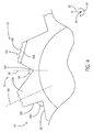
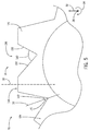
- the first slope 130 is greater than the second slope 132, such that each tooth 120 of the plurality of teeth 116 has an asymmetrical shape relative to the radial axis 32 through the one tooth 120, as illustrated in FIGS. 4 and 5 .
- each tooth 120 in the embodiment of FIG. 6 has an inverted-Y shape, which includes an angled base portion 137 (e.g., diverging or converging base portion) and a straight tip portion 138 (e.g., rectangular tip portion).
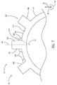
- each tooth 120 in the embodiment of FIG. 7 has an inverted-T shape or an I-shape, which includes an arcuate base portion 137 and a straight tip portion 138 (e.g., rectangular tip portion).
- a portion of the plurality of teeth 116 has an asymmetrical shape relative to the radial axis 32, and another portion of the plurality of teeth has a symmetrical shape relative to the radial axis 32.
- the slope 130 of one tooth 120 and the slope 132 of an adjacent tooth 120 may form one or more angles 140 between each tooth 120.
- the one or more angles 140 may be disposed between the slopes 130, 132 (as illustrated in FIGS. 4-6 ) or may be between the slope 130, 132 and an innermost outer perimeter 142 of the rigid portion 70 ( as illustrated in FIG. 6 ).
- the angle 140 may be equal to or greater than approximately 90 degrees, e.g., 90, 100, 115, 120, 135, 145, or more.
- the slopes 130, 132 may each form an acute angle 141, 143, respectively, relative to the radial axis 34.
- the acute angles 141, 143 (e.g., less than 90 degrees) may be the same or different relative to one another.
- the angle 141 is equal to or greater than the angle 143.
- the angle 141 is equal to or less than the angle 143.
- the acute angles 141, 143 may be any angles between approximately 1 degree and approximately 90 degrees. For example, 1, 5, 10, 15, 20, 25, 30, 35, 40, 45, 65, 75, and 85.
- a sum of the angles 141, 143 is approximately equal to the angle 140.
- a tooth tip 146 (e.g., outermost radial perimeter of the rigid portion 70) may be flat (e.g., smooth or non-contoured), as illustrated in FIGS. 5-7 .
- the tooth tip 146 may be variably textured or contoured, as illustrated in FIG. 4 .
- the tooth tip 146 may have a plurality of slopes 150 forming recesses and protrusions across at least a portion of a length 154 of the tooth 120.
- the rigid portion 70 may include a combination of flat and contoured tooth tips 146.
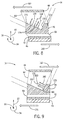
- FIGS. 8 and 9 illustrate a portion of the shear stress sensitive area of the rotational coupling 16 loaded in compression by the rigid portion 70.
- shear loading 162 on the first elastomeric portion 64 is in a direction substantially opposite to the drive direction 160.
- the first elastomeric portion 64 As the first elastomeric portion 64 stretches and twists in the direction of the shear loading 162, the first elastomeric portion 64 exerts a first force 168 on the rigid portion 70 in a direction away from the outer body portion 48 and toward a first tooth surface 170 corresponding to the slope 130 of the plurality of teeth 116. Similarly, a first tooth surface 170 exerts a second force 174 against the first elastomeric portion 64 radially outward 32 in a direction away from the first tooth surface 170 and toward the outer body portion 48. As such, the forces 168, 174 are orthogonal to the first tooth surface 170 and substantially opposite to each other.
- the rigid portion 70 e.g., the first tooth surface 170
- the rigid portion 70 locally loads the first elastomeric portion 64 in compression along the circumferential direction 34 about the rotational axis 28, thereby relieving the shear stress on the first elastomeric portion 64 caused by the shear loading 162. That is, the plurality of teeth 116 load the first elastomeric portion 64 radially in compression, rather than radially in shear compared to conventional flexible in-shear couplings that do not include the rigid portion 70.
- the shear loading 162 is in a direction opposite a reverse drive direction 176. Similar to the first tooth surface 170, a second tooth surface 180 corresponding to the slope 132 exerts a third force 182 on the elastomeric portion 64 radially outward 32 in a direction away from the second tooth surface 180 and toward the outer body portion 48. Similarly, the first elastomeric portion 64 exerts a fourth force 183 on the rigid portion 70 in a direction away from the outer body portion 48 and toward the second tooth surface 180 corresponding to the slope 132 of the plurality of teeth 116. As such, the forces 182, 183 are orthogonal to the second tooth surface 180 and substantially opposite to each other.
- the second tooth surface 180 loads the first elastomeric portion 64 in compression, as discussed above, decreasing the shear stress caused by the shear loading 162 compared to flexible couplings that do not include the rigid portion 70.
- slopes 130, 132 are substantially orthogonal, and thus the third force 182 is substantially orthogonal to the second force 174.
- the tooth tip 146 includes the plurality of slopes 150 (as shown in FIG. 4 )
- the plurality of slopes 150 may further reduce shear stress from the shear loading 162 in a similar manner.
- the slopes 130, 132 of the tooth 120 that are at an increased angle result in an increased reaction force that may be advantageous in managing load reversals that may be damaging to the elastomeric element of an elastomer-in-shear coupling
- the conductivity of the rigid portion 70 may dissipate the heat throughout the elastomeric portions 64, 68, which may have a low thermal conductivity (e.g., approximately 0.15 Watt/(meter Kelvin) (W/(mK)) compared to the thermal conductivity of the rigid portion 70.
- the rigid portion 70 may have a thermal conductivity that is at least 1.5 times greater, or up to in-excess of 1000 times greater than the thermal conductivity of the elastomer portions 64, 68.
- the rigid portion 70 may have a thermal conductivity of between approximately 0.25 W/(mK) and approximately 205 W/(mK) depending on the material used to fabricate the rigid portion 70.
- the rigid portion 70 may increase the durability of the elastomeric portions 64, 68 in flexible in-shear couplings, such as the rotational coupling 16.
- the rotational coupling 16 may enable the systems 10, 80 to operate for greater than typical (e.g., above approximately 20,000 hours for a reciprocating gas engine) before replacing the rotational coupling 16.
- typical e.g., above approximately 20,000 hours for a reciprocating gas engine
- the operational and maintenance costs associated with flexible in-shear couplings that include a rigid portion 70 may be decreased.
- the improved durability of the rotational coupling 16 may increase the overall performance and reliability of the system 10, 80 compared to systems that do not include flexible in-shear couplings having the disclosed rigid portion 70.
- the rotational coupling 16 may be manufactured via injection molding, overmolding, or any other suitable manufacturing techniques, and combinations thereof.
- the rigid portion 70 may be overmolded in place with the elastomeric portions 64, 68 between the inner and outer body portions 48, 50.
- the rigid portion 70 may include features to enable bonding (e.g., adherence) of the elastomeric portions 64, 68 to surfaces of the rigid portion 70 and the inner and outer body portions 48, 50.
- At least a portion of the rigid portion 70 may include a textured surface 184 to increase a surface area of the rigid portion 70, and facilitate bonding (e.g., adhering) of the elastomeric portions 64, 68 to surfaces of the rigid portion 70.
- one or more surfaces of the rigid portion 70 may be grit blasted, etched, sanded, or otherwise texturized to generate the textured surface 184.
- one or more surfaces of the rigid portion 70 (including the surface features 78) may include a plurality of recesses (e.g., a pattern of cylindrical, rectangular, or crisscrossing recesses) to generate the textured surface 184.
- the textured surface 184 may be on any surface of the rigid portion 70 in contact with the elastomeric portions 64, 68.
- surfaces 72, 74 of the body portions 48, 50 may also be texturized in a similar manner to increase a surface area of the surfaces 72, 74, and bonding of the elastomeric portions 64, 68 to the body portions 48, 50.
- each respective elastomeric portion 64, 68 may be injected into the annular space 62 between the body portions 48, 50.
- FIGS. 10 and 11 illustrate an elastomer injection system 186 that may be used to generate the rotational coupling 16.
- the system 186 includes first and second elastomer injectors 188, 190, respectively, and a system controller 192. While the illustrated embodiment includes two elastomer injectors 188, 190, the system 186 may include any suitable number of elastomer injectors 188, 190. For example, the system 186 may include 1, 2, 3, 4, 5 or more elastomer injectors 188, 190.
- the elastomer injectors 188, 190 may each be fluidly coupled to one or more elastomer supply units 193.
- the elastomer supply units 193 may supply each elastomeric injector 188, 190 with the same or a different resilient material (e.g., elastomeric material).
- the first elastomer injector 188 may inject a first desired elastomer 194 from the one or more elastomer supply units 193 through one or more first radial injection openings 196 (e.g., radial ports or passages) through the outer body portion 48 and/or through one or more first axial injection openings 202 (e.g., axial ports or passages) on one or both sides 36, 42.
- first radial injection openings 196 e.g., radial ports or passages
- first axial injection openings 202 e.g., axial ports or passages
- the second elastomer injector 190 may inject a second desired elastomer 198 through one or more second radial injection openings 200 (e.g., radial ports or passages) through the inner body portion 50 and/or through one or more second axial injection openings 204 (e.g., axial ports or passages) on one or both sides 36, 42.
- the openings 196, 200, 202, and 204 may be spaced apart from one another in a circumferential direction 34 about the axis 28, 30.
- the elastomer injectors 188, 190 may inject the elastomers 194, 198 at multiple regions of the annular space 62. Accordingly, the elastomers 194, 198 may uniformly fill annular passages 202, 204 defined by the inner surfaces 72, 74 and a respective surface of the rigid portion 70, thereby forming the elastomeric portions 64, 68.
- At least one or both of the elastomers 188, 190 flow through one or more radial passages 206 (e.g., internal passages) disposed through the rigid portion 70, as illustrated in FIG. 11 .
- the radial passages 206 may connect the elastomeric portions 64, 68, and provide additional support to retain the rigid portion 70 within the annular space 62 of the rotational coupling 16. As illustrated in FIG. 12 , the radial passages 206 extend through the rigid portion 70 between an inner perimeter 208 and the outer perimeters 114, 142.
- the one or more radial passages 206 may be spaced apart from one another (e.g., by a distance 210) in the circumferential direction 34 about the axial axis 28, 30 as illustrated in FIG. 12 , and may be spaced apart from one another in the axial direction 30 as illustrated in FIG. 11 . That is, the rigid portion 70 may have multiple rows and colunms of the one or more radial passages 206 in the circumferential and axial directions 32, 30.
- the one or more radial passages 206 may be located in the thickest portions (e.g., first radial dimension 212), thinnest portions (e.g., second radial dimension 214), and/or intermediate thickness portions (e.g., between dimensions 212, 214) of the rigid portion 70, such as defined by the plurality of teeth 116. As illustrated, the first radial dimension 212 is greater than the second radial dimension 214. In some embodiments, the one or more radial passages 206 may be located only in the thickest portions (e.g., first radial dimension 212) of the rigid portion 70.
- the elastomers 194, 198 may extend partially or completely through the one or more radial passages 206 (as illustrated by arrows 216 in FIG. 11 ), thereby connecting the elastomer portions 64, 68. Therefore, the elastomers 194, 198 may reinforce and secure the rigid portion 70 to the rotational coupling 16.
- the portions 64, 68 may have a common elastomer 194, 198. That is, the elastomers 194, 198 may have substantially identical chemical and physical properties. In other embodiments, the elastomeric portions 64, 68 may have elastomers 194, 198 having different chemical and physical properties. For example, the elastomer 194 supplied to the first elastomeric portion 64 may have a greater torsional softness (or lesser hardness) compared to the elastomer 198 supplied to the second elastomeric portion 68. This may be due, in part, to the higher shear loading 162 on the first elastomeric portion 64 compared to the second elastomeric portion 68.
- the increased torsional softness of the elastomer 194 in the first elastomeric portion 64 compared to the elastomer 198 in the second elastomeric portion may facilitate shear torque transfer from the first shaft 13 to the second shaft 15, as discussed above with reference to FIGS. 1 and 2 .
- the elastomer 194 supplied to the first elastomeric portion 64 may have a lesser torsional softness (or greater hardness) compared to the elastomer 198 supplied to the second elastomeric portion 68.
- the elastomer 198 may be at least 1.1, 1.2, 1.3, 1.4, 1.5, 1.6, 1.7, 1.8, 1.9, 2, 2.5, 3, 4, 5, 6, 7, 8, 9, 10, or more times stiffer or harder than the elastomer 194, or vice versa, using a unit of measure such as Young's modulus or Shore's durometer.
- the system controller 192 commands operation of the elastomeric injection system 186 to inject a desired amount of the elastomer 194, 198 into the annular passages 202, 204, as illustrated by arrows 218, 220.
- the system controller 192 may include devices employing a general purpose or an application-specific processor 224, both of which may include memory circuitry 228 for storing data relating to elastomer flow rates, flexible coupling dimensions (e.g., annular space, annular passage, and rigid portion dimensions, number of radial passages 206, etc.), and elastomer properties (e.g., viscosity, density, stiffness, softness, damping, cure times, etc).
- flexible coupling dimensions e.g., annular space, annular passage, and rigid portion dimensions, number of radial passages 206, etc.
- elastomer properties e.g., viscosity, density, stiffness, softness, damping, cure times, etc.
- the system controller 192 may include, or couple with, a variety of user interfaces, such as a display or monitor, a keyboard, a mouse, and a printer for generating hard copy output of injection, coupling, and/or elastomer parameters and images of the rotational coupling 16.
- user interfaces such as a display or monitor, a keyboard, a mouse, and a printer for generating hard copy output of injection, coupling, and/or elastomer parameters and images of the rotational coupling 16.
- the system controller 192 may control injection of the elastomers 194, 198 based on material properties of the elastomers 194, 198 and a dimension of the elastomer portions 64, 68 and the rigid portion 70.
- the annular space 62 of the rotational coupling 16 has a radial dimension 230 radially 32 extending between the body portions 48, 50.
- the annular space 62 includes the elastomeric portions 64, 68 and the rigid portion 70.
- the rigid portion 70 includes the radial dimension 212 radially 32 extending between the first outer perimeter 114 and the inner perimeter 208.
- the elastomeric portions 64, 68 include radial dimensions 232, 236, respectively.
- the radial dimension 232 extends radially 32 between the first inner surface 72 of the outer body portion 48 and the perimeter 114 or 142.
- the radial dimension 236 extends radially 32 between the second inner surface 74 of the inner body portion 50 and the inner perimeter 208 of the rigid portion 70.
- the radial dimensions 232, 236 may be the same or different.
- the radial dimension 232 may be greater than the radial dimension 236, thereby providing a greater stiffness in the elastomer portion 68 relative to the elastomer portion 64.
- the radial dimension 232 may be lesser than the radial dimension 236, thereby providing a greater stiffness in the elastomer portion 64 relative to the elastomer portion 68.
- the radial dimension 232 may be at least 5, 10, 15, 20, 25, 30, 35, 40, 45, 50, 75, 100, 150, 200, 250, or 300 percent greater than the radial dimension 236, or vice versa.
- the controller 192 may calculate the radial dimensions 232, 236 to achieve a desired stiffness in the elastomer portions 64, 68, or the controller 192 may calculate the desired material composition (e.g., Young's modulus) of the elastomers 194, 198 to achieve a desired stiffness in the elastomer portions 64, 68, or a combination thereof. Therefore, the controller 192 may control the selection and/or mixing of elastomeric materials to help achieve a desired stiffness in the elastomer portions 64, 68.
- the desired material composition e.g., Young's modulus
- the controller 192 also may calculate a volume of the elastomers 194, 198 to be injected into the elastomeric portions 64, 68, and the controller 192 may increase and or decrease a flow rate, pressure, and/or temperature of the elastomers 194,198 injected into the respective elastomeric portion 64, 68 based on the radial dimensions 232, 236. In certain embodiments, the controller 192 may adjust the flow rate of the elastomers 194, 198 to complete the injection into the respective elastomeric portion 64, 68 simultaneously regardless of differences in the radial dimensions 232, 236.
- certain embodiments of the rotational coupling 16 include multiple layers 22 radially extending between the outer body portion 48 and the inner body portion 50.
- the multiple layers include the elastomeric portions 64, 68 and the rigid portion 70.
- the rigid portion 70 includes the plurality of teeth 116 and recess 136 (e.g., slopes 130, 132) that load the shear forces (e.g., shear loading 162) in compression, rather than in shear, during torque transfer between the rotating shafts 13, 15.
- the first elastomeric portion 64 may include an elastomer (e.g., the elastomer 194) having a greater torsional softness (or lesser stiffness) compared to the elastomer (e.g., the elastomer 198) in the second elastomeric portion 68.
- the elastomers 194, 198 may be compound tuned such that the elastomeric portions 64, 68 maintain a torsional softness similar to a flexible coupling that does not include the rigid portion 70.
- the durability of the flexible in-shear couplings may be increased by loading areas sensitive to shear stress in compression, rather than in shear. In this way, the overall operational and maintenance costs of the system 10, 80 may be decreased, and system reliability may be increased for the system 10, 80 (e.g., power generation system).
Landscapes
- Engineering & Computer Science (AREA)
- General Engineering & Computer Science (AREA)
- Mechanical Engineering (AREA)
- Vibration Prevention Devices (AREA)
- Springs (AREA)
Abstract
A system includes a rotational coupling (116) including a first rotational joint (24), a second rotational joint (26), and a coupling body (18) disposed between the first and second rotational joints. The coupling body (18) includes first and second body portions disposed about a rotational axis (28), and a layered portion (20) disposed about the rotational axis (28) radially between the first and second body portions. The layered portion (20) includes first and second elastomeric portions (64, 68) disposed about the rotational axis (28), and a rigid portion (70) disposed about the rotational axis radially between the first and second elastomeric portions (64, 68). The rigid portion includes a plurality of radial protrusions (116).
Description
- The subject matter disclosed herein relates to a mechanical coupling, and, more particularly to a rotational coupling to transfer torque between machinery.
- A rotational coupling may be used to transfer torque between a variety of machinery, such as an engine and a load. For example, a power generation system may include an engine (e.g., reciprocating engine or gas turbine) drivingly coupled to an electric generator. Depending on the configuration, the power generation system may produce between 100kW and 10MW or more of electricity. In such power generation systems and other heavy machinery, the rotational coupling may be susceptible to wear and/or degradation due to torque, vibration, shock, misalignment, thermal stress, and/or mechanical stress.
- Certain embodiments commensurate in scope with the originally claimed subject matter are summarized below. These embodiments are not intended to limit the scope of the claimed subject matter, but rather these embodiments are intended only to provide a brief summary of possible forms of the present disclosure. Indeed, the present disclosure may encompass a variety of forms that may be similar to or different from the embodiments set forth below.
- In a first embodiment, a system includes a rotational coupling including a first rotational joint, a second rotational joint, and a coupling body disposed between the first and second rotational joints. The coupling body includes first and second body portions disposed about a rotational axis, and a layered portion disposed about the rotational axis radially between the first and second body portions. The layered portion includes first and second elastomeric portions disposed about the rotational axis, and a rigid portion disposed about the rotational axis radially between the first and second elastomeric portions. The rigid portion includes a plurality of radial protrusions.
- In a second embodiment, a system includes a coupling including a central axis, an inner body portion disposed about the central axis, an outer body portion disposed about the inner body portion, and a layered portion disposed about the central axis radially between the inner and outer body portions. The layered portion includes inner and outer elastomeric portions disposed about the central axis, and a rigid portion disposed about the central axis radially between the inner and outer elastomeric portions. The rigid portion includes a plurality of radial protrusions interfacing with the outer elastomeric portion.
- In a third embodiment, a method includes transferring torque through a layered portion of a rotational coupling between first and second machines. The layered portion includes first and second elastomeric portions disposed about a rotational axis, and a rigid portion disposed about the rotational axis radially between the first and second elastomeric portions. The rigid portion includes a plurality of radial protrusions.
- These and other features, aspects, and advantages of the present disclosure will become better understood when the following detailed description is read with reference to the accompanying drawings in which like characters represent like parts throughout the drawings, wherein:
-
FIG. 1 is a block diagram of an embodiment of a machine system having a flexible in-shear coupling, wherein the flexible in-shear coupling includes a plurality of layers having at least one rigid layer between two resilient layers; -
FIG. 2 is a block diagram of an embodiment of an engine-generator system having the flexible in-shear coupling ofFIG. 1 ; -
FIG. 3 is a cross-sectional side view of an embodiment of the flexible in-shear coupling ofFIG. 1 taken along line 3-3, wherein the rigid layer includes a toothed interleaf; -
FIG. 4 is a partial cross-sectional side view of an embodiment of the toothed interleaf ofFIG. 3 , wherein the toothed interleaf includes asymmetrical teeth; -
FIG. 5 is a partial cross-sectional side view of an embodiment of the toothed interleaf ofFIG. 3 , wherein the toothed interleaf includes a textured surface; -
FIG. 6 is a partial cross-sectional side view of an embodiment of the toothed interleaf ofFIG. 3 , wherein the toothed interleaf includes symmetrical teeth having an inverted Y -shape; -
FIG. 7 is a partial cross-sectional side view of an embodiment of the toothed interleaf ofFIG. 3 , wherein the toothed interleaf includes symmetrical teeth having an inverted T-shape; -
FIG. 8 is a side view of an embodiment of the flexible in-shear coupling ofFIG. 1 , wherein one of the resilient layers is loaded in compression in a drive direction; -
FIG. 9 is a partial cross-sectional side view of an embodiment of the flexible in-shear coupling ofFIG. 1 , wherein one of the resilient layers is loaded in compression in a reverse drive direction; -
FIG. 10 is a block diagram of an embodiment of an elastomer injection system, wherein the elastomer injection system injects an elastomer into an annular region of the flexible in-shear coupling to generate the resilient layers and secure the toothed interleaf; -
FIG. 11 is a block diagram of an embodiment of the elastomer injection system ofFIG. 10 , wherein the injected elastomer flows through radial passages through the toothed interface and connects the resilient layers disposed on each side of the toothed interface; -
FIG. 12 is a partial cross-sectional side view of an embodiment of the toothed interface ofFIG. 3 , wherein the toothed interface includes a plurality of radial passages extending through a radial dimension of the toothed interface; and -
FIG. 13 is a block diagram of an embodiment of the flexible in-shear coupling ofFIG. 3 , wherein the resilient layers have a variable radial dimension. - One or more specific embodiments of the present disclosure will be described below. In an effort to provide a concise description of these embodiments, all features of an actual implementation may not be described in the specification. It should be appreciated that in the development of any such actual implementation, as in any engineering or design project, numerous implementation-specific decisions must be made to achieve the developers' specific goals, such as compliance with system-related and business-related constraints, which may vary from one implementation to another. Moreover, it should be appreciated that such a development effort might be complex and time consuming, but would nevertheless be a routine undertaking of design, fabrication, and manufacture for those of ordinary skill having the benefit of this disclosure.
- When introducing elements of various embodiments of the present disclosure, the articles "a," "an," "the," and "said" are intended to mean that there are one or more of the elements. The terms "comprising," "including," and "having" are intended to be inclusive and mean that there may be additional elements other than the listed elements.
- The present disclosure relates to flexible couplings for transmitting torque between machinery, such as shafts of dual shaft power generation systems (e.g., engine-generator sets). For example, the flexible coupling may connect an engine shaft with a corresponding load shaft of a generator or gearbox. The flexible coupling includes a layered portion having a plurality of resilient portions (e.g., resilient material) disposed about a rigid portion (e.g., rigid material). The layered portion (e.g., toothed rigid material sandwiched between resilient material) may help to improve shaft alignment, damp vibration, absorb shock (e.g., due to sudden changes in torque and/or reversal in torque), reduce thermal stress, and reduce mechanical stress, while also transferring torque between machinery (e.g., engine to generator, or gearbox). For example, the resilient material may accommodate shaft misalignment, in particular, in engine-generator sets that include at least one resiliently mounted engine and/or generator, or gearbox. By further example, the resilient material in the flexible coupling may provide a cushion for vibrations associated with operation of the system, thereby damping the vibrations and mitigating noise, and not limited to engine-generator sets that include at least one resiliently mounted engine, generator, or gearbox and also applicable to rigidly mounted engine and rigidly mounted driven article.
- Various types of couplings may incorporate a resilient material to transfer torque from one rotating shaft to an adjacent shaft. For example, flexible in-shear couplings, such as toothed type couplings and low radial/high flexibility couplings, transfer torque via shear forces. Other flexible couplings include flexible in-compression couplings, which transfer torque via compression forces. Properties of the resilient material in the flexible couplings may depend on the manner in which the flexible couplings transfers the torque (e.g., via compression or shear). For example, the resilient material used for flexible in-compression couplings may have a higher degree of torsional stiffness compared to the resilient material used for flexible in-shear couplings (e.g., elastomer in-shear couplings), which generally have a higher degree of torsional softness. Unlike flexible in-compression couplings, which transfer torque via compression, the resilient material in the flexible in-shear couplings stretches and twists during torque transfer. The stretching and twisting of the resilient material may result in areas of high stress load that may decrease the overall durability of the resilient material in the flexible in-shear couplings compared to the flexible in-compression couplings. For example, the high stress load, in combination with elevated system temperatures, may cause the resilient material to wear and breakdown (e.g., degrade), thereby decreasing system performance and reliability. As such, without the disclosed embodiments, flexible in-shear couplings may be replaced more frequently compared to flexible in-compression couplings, increasing equipment and maintenance costs, e.g., for dual shaft power generation systems that use flexible in-shear couplings for torque transfer. Accordingly, it may be desirable to configure a flexible in-shear coupling to locally load high stress areas in compression, rather than in shear, while maintaining the desired torsional softness of the resilient material. By locally loading areas of the flexible coupling sensitive to the shear load, the durability of the flexible in-shear coupling may be increased.
-
FIG. 1 illustrates a block diagram of asystem 10 having first andsecond machines rotational coupling 16 includes acoupling body 18 having a layeredportion 20 with a plurality oflayers 22 of alternating resilient and rigid materials in a sandwich arrangement (e.g., concentric layers). As discussed in detail below, therotational coupling 16 may improve system durability, operability, and reliability by loading certain regions of the resilient material in compression, rather than in shear. As shown inFIG. 1 , therotational coupling 16 includes first and secondrotational joints respective shafts second machines first machine 12 provides power and/or transfers torque to drive thesecond machine 14, and thus thefirst machine 12 may include an engine or driving machine while thesecond machine 14 may include a load or driven machine. In certain embodiments, thesecond machine 14 provides power and/or transfers torque to drive thefirst machine 12, and thus thesecond machine 14 may include an engine or driving machine while thefirst machine 12 may include a load or driven machine. - The engine or driving machine (e.g., 12 or 14) may include, but is not limited to, a gas turbine, a steam turbine, a wind turbine, a hydro turbine, a reciprocating engine (discussed in detail below with reference to
FIG. 2 ), an electric motor, or any combination thereof. The load or driven machine (e.g., 12 or 14) may include, but is not limited to, a vehicle or a stationary load. By way of example, the load or driven machine may include an electrical generator of apower generation system 10, a compressor, a pump, an industrial machine or automation system, a drivetrain of a vehicle, a propeller of an aircraft or watercraft, or any suitable device capable of being powered by the rotational output of the engine or driving machine. - As discussed above, the
rotational coupling 16 links (e.g., connects) theshafts first shaft 13 to thesecond shaft 15 or vice versa, depending on whichmachines direction 30, a radial axis ordirection 32, and/or a circumferential axis ordirection 34 of therotational coupling 16. In the illustrated embodiment, the first rotational joint 24 on afirst side 36 of therotational coupling 16 has a first hub 40 (e.g. a flywheel), while the second rotational joint 26 on asecond side 42 has a second hub 46 (e.g., a flywheel). The first andsecond hubs machines second hubs coupling body 18, such that the layeredportion 20 withlayers 22 is disposed between and thus transfers torque between thehubs rotational coupling 16 includes an outer body portion 48 (e.g., annular body portion) that couples to thehub 40, and an inner body portion 50 (e.g., annular or cylindrical body portion) that couples to thehub 46. Theouter body portion 48 is disposed circumferentially 34 about the layeredportion 20, theinner body portion 50 and at least a portion of thehub 46, thesecond shaft 15, or a combination thereof (e.g., in a coaxial or concentric arrangement). Theinner body portion 50 is disposed circumferentially 34 about at least a portion of thehub 46, thesecond shaft 15, or a combination thereof (e.g., in a coaxial or concentric arrangement). The layeredportion 20 withlayers 22 is disposed radially 32 between thebody portions portion 20 is sandwiched between (and separates) thebody portions body portions body portions layers 22 in the layeredportion 20, and subsequently through the other of the body portions (e.g., 48 or 50), thereby enabling torque transfer between themachines - The
rotational joints outer body portion 48 may include a plurality of fasteners 52 (e.g., threaded fasteners) securing thehub 40 to theouter body portion 48. By further example, the rotational joint 26 at theinner body portion 50 may include thehub 46 and an opening 54 (e.g., annular opening) that accommodates at least a portion of thehub 46 and/or thesecond shaft 15. For example, theannular opening 54 may have a radial dimension 58 that is greater than or equal to a shaft dimension 60. The rotational joint 26 may include an internal joint 56 within theopening 54, thereby internally securing theshaft 15 and/or thehub 46 within theopening 54 of theinner body portion 50. The internal joint 56 may include a male-female joint, such as a key in slot joint, a spline joint, or any combination thereof. Alternatively or additionally, the rotational joint 26 may include a plurality of fasteners 52 (e.g., threaded fasteners or bolts) securing theshaft 15 and/or thehub 46 to theinner body portion 50. In operation, if themachine 12 drives themachine 14, then torque may be transferred through the first rotational joint 24 to theouter body portion 48, sequentially through thelayers 22 in the layeredportion 20, and then out through theinner body portion 50. Alternatively, if themachine 14 drives themachine 12, then torque may be transferred through the second rotational joint 26 to theinner body portion 50, sequentially through thelayers 22 in the layeredportion 20, and then out through theouter body portion 48. - The
body portions annular space 62 that supports the layeredportion 20. The layeredportion 20 in theannular space 62 is disposed circumferentially 34 about theinner body portion 50, and theouter body portion 48 is circumferentially 34 about the layeredportion 20 in theannular space 62. The layeredportion 20 includes a plurality oflayers 22 disposed within theannular space 62 that facilitate torque transfer between thebody portions shafts rigid portion 70. Theresilient portions portions elastomeric portions distance 71 corresponding to a radial dimension of therigid portion 70. That is, therigid portion 70 is sandwiched between theelastomeric portions elastomeric portion 64 is radially 32 away from theinner body portion 50 and abuts a firstinner surface 72 of theouter body portion 48 and therigid portion 70. The secondelastomeric portion 68 is radially 32 away from theouter body portion 48 and abuts a secondinner surface 74 associated with theinner body portion 50 and therigid portion 70. Accordingly, the firstelastomeric portion 64 is circumferentially 34 about theinner body portion 50, the secondelastomeric portion 68, and therigid portion 70. Therigid portion 70 is circumferentially 34 about theinner body portion 50 and the secondelastomeric portion 68. The secondelastomeric portion 68 is circumferentially 34 about theinner body portion 50. In other words, the layeredportion 20 has the first and secondelastomeric portions rotational axis 28, and therigid portion 70 disposed about therotational axis 28 radially 32 between the first and secondelastomeric portions - The
elastomeric portions shafts shafts system 10. In certain embodiments, the resilient material (e.g., elastomeric material) in theelastomeric portions elastomeric portion elastomeric portions - As discussed above, without the disclosed embodiments, the shear load between the
rotational joints rotational coupling 16, may have a reduced hardness (e.g., torsional stiffness) compared to resilient materials used, for example, in flexible in-compression couplings. The reduced torsional stiffness of the resilient material for flexible in-shear couplings provides the desired flexibility to enable torque transfer via shear loading. However, the reduced torsional stiffness of the resilient material also results in areas of high shear stress during shear loading that may decrease the overall durability of the flexible in-shear coupling. Therefore, without the disclosed embodiments, the flexible in-shear couplings may be replaced frequently, resulting in increased maintenance and replacement costs for power generating (or pumping, or drive) system that use flexible in-shear couplings compared to systems that use flexible in-compression couplings to transfer torque. - To mitigate the undesirable effects of the shear load, the
rigid portion 70 is interleafed between theelastomeric portions portion 20 of therotational coupling 16. Therigid portion 70 may include rigid materials such as, but not limited to, metals, metal alloys, glass-filled nylon, or other suitable reinforced composite materials (e.g., reinforcing materials distributed throughout a matrix material), and combinations thereof. For example, the composite materials may include a thermally conductive material (e.g., metal fibers) distributed in a conductive or non-conductive material, or non-conductive fibers distributed in a conductive matrix material. Therigid portion 70 may include surface features 78 (e.g., protrusions, recesses, teeth, etc.) that increase the durability of theelastomeric portions FIGS. 3-9 , the surface features 78 may load the shear forces in areas sensitive to shear degradation in compression. As should be noted, therigid portion 70 may increase the stiffness of theelastomeric portions elastomeric portions rigid portion 70. - In addition to relieving stress on the
elastomeric portions rigid material 70 may increase conductivity of the plurality oflayers 22 to enhance cooling of theelastomeric portions elastomeric portions system 10. Therefore, the temperature of theelastomeric portions rigid portion 70 may have a suitable thermal conductivity to dissipate the heat throughout theelastomeric portions elastomeric portions system 10. -
FIG. 2 illustrates a block diagram of an embodiment of a portion of an engine drivenpower generation system 80 having a reciprocatinginternal combustion engine 82, which may provide the rotational output (e.g., torque) to thesecond machine 14 via therotational coupling 16. Thesystem 80 includes the engine 82 (e.g., a reciprocating internal combustion engine) having one or more combustion chambers 84 (e.g., 1, 2, 3, 4, 5, 6, 7, 8, 10, 12, 14, 16, 18, 20, 21, 22, 23, 24, or more combustion chambers 84) within an engine block and/orcylinder block 83. Theengine 82 also includes an engine manifold 86 (e.g., intake manifold and exhaust manifold), which may be coupled to an oxidant supply 90 and afuel supply 92. The oxidant supply 90 (e.g., an air supply) is configured to provide a pressurized oxidant 90, such as air, oxygen, oxygen-enriched air, oxygen-reduced air, or any combination thereof, to eachcombustion chamber 84. Thefuel supply 92 is configured to provide a fuel 92 (e.g., liquid and/or gaseous fuel) to eachcombustion chamber 84. Thefuel 92 may be any suitable gaseous fuel, such as natural gas, associated petroleum gas, propane, biogas, sewage gas, landfill gas, coal mine gas, for example. Thefuel 92 may also include a variety of liquid fuels, such as gasoline or diesel fuel. During operation, eachcombustion chamber 84 combusts a mixture of thefuel 92 with oxidant 90 to generate hot pressurized combustion gases, which in turn cause apiston 98 adjacent to eachcombustion chamber 84 to move linearly within acylinder 100. Thereciprocating pistons 98, driven by combustion gases, in turn drive rotation of acrankshaft 101, which causing the first shaft 13 (e.g., an engine shaft) to rotate circumferentially 34 about therotational axis 28. - Further, the
first shaft 13 may be coupled to therotational coupling 16 via aflywheel 102, which couples thefirst shaft 13 to thefirst side 36 of therotational coupling 16. The first rotational joint 24 may include theflywheel 102, which may be an example of thehub 40 inFIG. 1 . The first rotational joint 24 may include coupling features 108 on the coupling body 18 (e.g., outer body portion 48) of therotational coupling 16, and these coupling features 108 may couple with complementary features on theflywheel 102 to secure thecoupling body 18 to theflywheel 102. For example, the coupling features 108 may include an annular flange, a plurality of circumferentially spaced brackets, or a combination thereof, fixed to or integral with theouter body portion 48 of thecoupling body 18. Thecoupling body 18 and theflywheel 102 may be secured by fasteners 110 (e.g., threaded fasteners, bolts, screws, snap-on, etc.) extending through receptacles in the coupling features 108 and theflywheel 102. In certain embodiments, thefirst side 36 of thecoupling body 18 may abut a surface of theflywheel 102. In other embodiments, thefirst side 36 of thecoupling body 18 may be spaced apart from theflywheel 102, such that the plurality oflayers 22 within theannular opening 54 are not in direct contact with theflywheel 102. On thesecond side 42, second rotational joint 26 couples theinner body portion 50 to thesecond shaft 15 as described above with reference toFIG. 1 . In the illustrated embodiment, thesecond shaft 15 is coupled to a load 102 (e.g., an electrical generator), which is driven by theengine 82 causing rotation of thefirst shaft 13, therotational coupling 16, and thesecond shaft 15. - As discussed above, the
rigid portion 70 of therotational coupling 16 includes the surface features 78 shaped to load shear stress sensitive areas of theelastomeric portions FIG. 3 is a cross-sectional side view of therotational coupling 16 ofFIGS. 1 and2 , taken within line 3-3, illustrating the surface features 78 of therigid portion 70. In the illustrated embodiment, the surface features 78 are disposed along anouter perimeter 114 of therigid portion 70. For example, therigid portion 70 includes a plurality of teeth 116 (e.g., radial protrusions) positioned radially outward 32 away from therotational axis 28 in a direction from theinner body portion 50 toward theouter body portion 48. Accordingly, the plurality ofteeth 116 is positioned at an interface 118 (e.g., a toothed interface) between theelastomeric portion 64 and therigid portion 70. In certain embodiments, for example when thehub 40 is coupled to theinner body portion 50, the plurality ofteeth 116 may extend radially inward toward therotational axis 28 in a direction away from theouter body portion 48 toward theinner body portion 50, such that the plurality ofteeth 116 is at an interface 119 (e.g., toothed interface) between theelastomeric portion 68 and therigid portion 70. - Each
tooth 120 of the plurality ofteeth 116 on theouter perimeter 114 of therigid portion 70 is circumferentially 34 spaced apart adistance 124 from anadjacent tooth 120. The plurality ofteeth 116 has afirst slope 130 and asecond slope 132 opposite thefirst slope 130. Theslopes recesses 136 that separates eachtooth 120 from anadjacent tooth 120. In the illustrated embodiment, theslopes axis outer body portion 48 in a direction toward therotational axis 28, thereby forming the plurality ofrecesses 136 between each pair ofadjacent teeth 120 of the plurality ofteeth 116. That is, thefirst slope 130 is in a first circumferential direction (e.g., rotational direction 36) about theaxis second slope 132 is in a second circumferential direction about theaxis slopes outer perimeter 114 depending on the desired shape and symmetry of the plurality ofteeth 116. In one embodiment, thefirst slope 130 is greater than thesecond slope 132, such that eachtooth 120 of the plurality ofteeth 116 has an asymmetrical shape relative to theradial axis 32 through the onetooth 120, as illustrated inFIGS. 4 and5 . In other embodiments, theslopes teeth 116 has a symmetrical shape relative to theradial axis 32, as illustrated inFIGS. 6 and7 . For example, eachtooth 120 in the embodiment ofFIG. 6 has an inverted-Y shape, which includes an angled base portion 137 (e.g., diverging or converging base portion) and a straight tip portion 138 (e.g., rectangular tip portion). By further example, eachtooth 120 in the embodiment ofFIG. 7 has an inverted-T shape or an I-shape, which includes anarcuate base portion 137 and a straight tip portion 138 (e.g., rectangular tip portion). In certain embodiments, a portion of the plurality ofteeth 116 has an asymmetrical shape relative to theradial axis 32, and another portion of the plurality of teeth has a symmetrical shape relative to theradial axis 32. Theslope 130 of onetooth 120 and theslope 132 of anadjacent tooth 120 may form one ormore angles 140 between eachtooth 120. For example, the one ormore angles 140 may be disposed between theslopes 130, 132 (as illustrated inFIGS. 4-6 ) or may be between theslope outer perimeter 142 of the rigid portion 70 ( as illustrated inFIG. 6 ). Theangle 140 may be equal to or greater than approximately 90 degrees, e.g., 90, 100, 115, 120, 135, 145, or more. - The
slopes acute angle radial axis 34. Theacute angles 141, 143 (e.g., less than 90 degrees) may be the same or different relative to one another. For example, in certain embodiments, theangle 141 is equal to or greater than theangle 143. In other embodiments, theangle 141 is equal to or less than theangle 143. Theacute angles angles angle 140. - In one embodiments, a tooth tip 146 (e.g., outermost radial perimeter of the rigid portion 70) may be flat (e.g., smooth or non-contoured), as illustrated in
FIGS. 5-7 . In other embodiments, thetooth tip 146 may be variably textured or contoured, as illustrated inFIG. 4 . For example, thetooth tip 146 may have a plurality ofslopes 150 forming recesses and protrusions across at least a portion of alength 154 of thetooth 120. In certain embodiments, therigid portion 70 may include a combination of flat andcontoured tooth tips 146. - As discussed above, the
rigid portion 70 loads the shear stress sensitive areas in compression.FIGS. 8 and 9 illustrate a portion of the shear stress sensitive area of therotational coupling 16 loaded in compression by therigid portion 70. For example, during operation of thesystem 10 in a drive direction 160 (e.g., clockwise rotation about the rotational axis 28),shear loading 162 on the firstelastomeric portion 64 is in a direction substantially opposite to thedrive direction 160. As the firstelastomeric portion 64 stretches and twists in the direction of theshear loading 162, the firstelastomeric portion 64 exerts afirst force 168 on therigid portion 70 in a direction away from theouter body portion 48 and toward afirst tooth surface 170 corresponding to theslope 130 of the plurality ofteeth 116. Similarly, afirst tooth surface 170 exerts asecond force 174 against the firstelastomeric portion 64 radially outward 32 in a direction away from thefirst tooth surface 170 and toward theouter body portion 48. As such, theforces first tooth surface 170 and substantially opposite to each other. In this way, the rigid portion 70 (e.g., the first tooth surface 170) locally loads the firstelastomeric portion 64 in compression along thecircumferential direction 34 about therotational axis 28, thereby relieving the shear stress on the firstelastomeric portion 64 caused by theshear loading 162. That is, the plurality ofteeth 116 load the firstelastomeric portion 64 radially in compression, rather than radially in shear compared to conventional flexible in-shear couplings that do not include therigid portion 70. - During revere mode operation of the
system shear loading 162 is in a direction opposite areverse drive direction 176. Similar to thefirst tooth surface 170, asecond tooth surface 180 corresponding to theslope 132 exerts athird force 182 on theelastomeric portion 64 radially outward 32 in a direction away from thesecond tooth surface 180 and toward theouter body portion 48. Similarly, the firstelastomeric portion 64 exerts afourth force 183 on therigid portion 70 in a direction away from theouter body portion 48 and toward thesecond tooth surface 180 corresponding to theslope 132 of the plurality ofteeth 116. As such, theforces second tooth surface 180 and substantially opposite to each other. Accordingly, thesecond tooth surface 180 loads the firstelastomeric portion 64 in compression, as discussed above, decreasing the shear stress caused by theshear loading 162 compared to flexible couplings that do not include therigid portion 70. In certain embodiments, slopes 130, 132 are substantially orthogonal, and thus thethird force 182 is substantially orthogonal to thesecond force 174. In embodiments where thetooth tip 146 includes the plurality of slopes 150 (as shown inFIG. 4 ), the plurality ofslopes 150 may further reduce shear stress from theshear loading 162 in a similar manner. Theslopes tooth 120 that are at an increased angle result in an increased reaction force that may be advantageous in managing load reversals that may be damaging to the elastomeric element of an elastomer-in-shear coupling - Additionally, the conductivity of the
rigid portion 70 may dissipate the heat throughout theelastomeric portions rigid portion 70. Therigid portion 70 may have a thermal conductivity that is at least 1.5 times greater, or up to in-excess of 1000 times greater than the thermal conductivity of theelastomer portions rigid portion 70 may have a thermal conductivity of between approximately 0.25 W/(mK) and approximately 205 W/(mK) depending on the material used to fabricate therigid portion 70. Therefore, by dissipating the heat and loading the shear force (e.g., the shear loading 162) in compression, therigid portion 70 may increase the durability of theelastomeric portions rotational coupling 16. For example, in certain embodiments, therotational coupling 16 may enable thesystems rotational coupling 16. As such, the operational and maintenance costs associated with flexible in-shear couplings that include arigid portion 70 may be decreased. Moreover, the improved durability of therotational coupling 16 may increase the overall performance and reliability of thesystem rigid portion 70. - As discussed in further detail below, with reference to
FIGS. 10 and11 , therotational coupling 16 may be manufactured via injection molding, overmolding, or any other suitable manufacturing techniques, and combinations thereof. For example, to facilitate coupling therigid portion 70 to therotational coupling 16, therigid portion 70 may be overmolded in place with theelastomeric portions outer body portions rigid portion 70 may include features to enable bonding (e.g., adherence) of theelastomeric portions rigid portion 70 and the inner andouter body portions rigid portion 70 may include atextured surface 184 to increase a surface area of therigid portion 70, and facilitate bonding (e.g., adhering) of theelastomeric portions rigid portion 70. By way of example, one or more surfaces of the rigid portion 70 (including the surface features 78) may be grit blasted, etched, sanded, or otherwise texturized to generate thetextured surface 184. In addition, one or more surfaces of the rigid portion 70 (including the surface features 78) may include a plurality of recesses (e.g., a pattern of cylindrical, rectangular, or crisscrossing recesses) to generate thetextured surface 184. Thetextured surface 184 may be on any surface of therigid portion 70 in contact with theelastomeric portions body portions surfaces elastomeric portions body portions - During manufacturing, the resilient material (e.g., elastomeric material) of each respective
elastomeric portion annular space 62 between thebody portions FIGS. 10 and11 illustrate anelastomer injection system 186 that may be used to generate therotational coupling 16. Thesystem 186 includes first andsecond elastomer injectors system controller 192. While the illustrated embodiment includes twoelastomer injectors system 186 may include any suitable number ofelastomer injectors system 186 may include 1, 2, 3, 4, 5 ormore elastomer injectors elastomer supply units 193. Theelastomer supply units 193 may supply eachelastomeric injector first elastomer injector 188 may inject a first desiredelastomer 194 from the one or moreelastomer supply units 193 through one or more first radial injection openings 196 (e.g., radial ports or passages) through theouter body portion 48 and/or through one or more first axial injection openings 202 (e.g., axial ports or passages) on one or bothsides second elastomer injector 190 may inject a second desiredelastomer 198 through one or more second radial injection openings 200 (e.g., radial ports or passages) through theinner body portion 50 and/or through one or more second axial injection openings 204 (e.g., axial ports or passages) on one or bothsides openings circumferential direction 34 about theaxis elastomer injectors elastomers annular space 62. Accordingly, theelastomers annular passages inner surfaces rigid portion 70, thereby forming theelastomeric portions - Additionally, in certain embodiments, at least one or both of the
elastomers rigid portion 70, as illustrated inFIG. 11 . Theradial passages 206 may connect theelastomeric portions rigid portion 70 within theannular space 62 of therotational coupling 16. As illustrated inFIG. 12 , theradial passages 206 extend through therigid portion 70 between aninner perimeter 208 and theouter perimeters radial passages 206 may be spaced apart from one another (e.g., by a distance 210) in thecircumferential direction 34 about theaxial axis FIG. 12 , and may be spaced apart from one another in theaxial direction 30 as illustrated inFIG. 11 . That is, therigid portion 70 may have multiple rows and colunms of the one or moreradial passages 206 in the circumferential andaxial directions radial passages 206 may be located in the thickest portions (e.g., first radial dimension 212), thinnest portions (e.g., second radial dimension 214), and/or intermediate thickness portions (e.g., betweendimensions 212, 214) of therigid portion 70, such as defined by the plurality ofteeth 116. As illustrated, the firstradial dimension 212 is greater than the secondradial dimension 214. In some embodiments, the one or moreradial passages 206 may be located only in the thickest portions (e.g., first radial dimension 212) of therigid portion 70. In any or all of these locations, theelastomers arrows 216 inFIG. 11 ), thereby connecting theelastomer portions elastomers rigid portion 70 to therotational coupling 16. - In one embodiment, the
portions common elastomer elastomers elastomeric portions elastomers elastomer 194 supplied to the firstelastomeric portion 64 may have a greater torsional softness (or lesser hardness) compared to theelastomer 198 supplied to the secondelastomeric portion 68. This may be due, in part, to thehigher shear loading 162 on the firstelastomeric portion 64 compared to the secondelastomeric portion 68. For example, the increased torsional softness of theelastomer 194 in the firstelastomeric portion 64 compared to theelastomer 198 in the second elastomeric portion may facilitate shear torque transfer from thefirst shaft 13 to thesecond shaft 15, as discussed above with reference toFIGS. 1 and2 . Alternatively, theelastomer 194 supplied to the firstelastomeric portion 64 may have a lesser torsional softness (or greater hardness) compared to theelastomer 198 supplied to the secondelastomeric portion 68. For example, theelastomer 198 may be at least 1.1, 1.2, 1.3, 1.4, 1.5, 1.6, 1.7, 1.8, 1.9, 2, 2.5, 3, 4, 5, 6, 7, 8, 9, 10, or more times stiffer or harder than theelastomer 194, or vice versa, using a unit of measure such as Young's modulus or Shore's durometer. - The
system controller 192 commands operation of theelastomeric injection system 186 to inject a desired amount of theelastomer annular passages arrows system controller 192 may include devices employing a general purpose or an application-specific processor 224, both of which may includememory circuitry 228 for storing data relating to elastomer flow rates, flexible coupling dimensions (e.g., annular space, annular passage, and rigid portion dimensions, number ofradial passages 206, etc.), and elastomer properties (e.g., viscosity, density, stiffness, softness, damping, cure times, etc). Thesystem controller 192 may include, or couple with, a variety of user interfaces, such as a display or monitor, a keyboard, a mouse, and a printer for generating hard copy output of injection, coupling, and/or elastomer parameters and images of therotational coupling 16. - In certain embodiment, the
system controller 192 may control injection of theelastomers elastomers elastomer portions rigid portion 70. For example, as illustrated inFIG. 13 , theannular space 62 of therotational coupling 16 has aradial dimension 230 radially 32 extending between thebody portions annular space 62 includes theelastomeric portions rigid portion 70. Therigid portion 70 includes theradial dimension 212 radially 32 extending between the firstouter perimeter 114 and theinner perimeter 208. Similarly, theelastomeric portions radial dimensions radial dimension 232 extends radially 32 between the firstinner surface 72 of theouter body portion 48 and theperimeter radial dimension 236 extends radially 32 between the secondinner surface 74 of theinner body portion 50 and theinner perimeter 208 of therigid portion 70. - The
radial dimensions radial dimension 232 may be greater than theradial dimension 236, thereby providing a greater stiffness in theelastomer portion 68 relative to theelastomer portion 64. In other embodiments, theradial dimension 232 may be lesser than theradial dimension 236, thereby providing a greater stiffness in theelastomer portion 64 relative to theelastomer portion 68. For example, theradial dimension 232 may be at least 5, 10, 15, 20, 25, 30, 35, 40, 45, 50, 75, 100, 150, 200, 250, or 300 percent greater than theradial dimension 236, or vice versa. In certain embodiments, thecontroller 192 may calculate theradial dimensions elastomer portions controller 192 may calculate the desired material composition (e.g., Young's modulus) of theelastomers elastomer portions controller 192 may control the selection and/or mixing of elastomeric materials to help achieve a desired stiffness in theelastomer portions controller 192 also may calculate a volume of theelastomers elastomeric portions controller 192 may increase and or decrease a flow rate, pressure, and/or temperature of the elastomers 194,198 injected into the respectiveelastomeric portion radial dimensions controller 192 may adjust the flow rate of theelastomers elastomeric portion radial dimensions - As discussed above, certain embodiments of the
rotational coupling 16 includemultiple layers 22 radially extending between theouter body portion 48 and theinner body portion 50. The multiple layers include theelastomeric portions rigid portion 70. Therigid portion 70 includes the plurality ofteeth 116 and recess 136 (e.g., slopes 130, 132) that load the shear forces (e.g., shear loading 162) in compression, rather than in shear, during torque transfer between therotating shafts elastomeric portion 64 may include an elastomer (e.g., the elastomer 194) having a greater torsional softness (or lesser stiffness) compared to the elastomer (e.g., the elastomer 198) in the secondelastomeric portion 68. Theelastomers elastomeric portions rigid portion 70. By including a rigid portion having a plurality of teeth, such as therigid portion 70, the durability of the flexible in-shear couplings may be increased by loading areas sensitive to shear stress in compression, rather than in shear. In this way, the overall operational and maintenance costs of thesystem system 10, 80 (e.g., power generation system). - This written description uses examples to disclose embodiments of the present disclosure, including the best mode, and also to enable any person skilled in the art to practice the disclosed embodiments, including making and using any devices or systems and performing any incorporated methods. The patentable scope of the present disclosure is defined by the claims, and may include other examples that occur to those skilled in the art. Such other examples are intended to be within the scope of the claims if they have structural elements that do not differ from the literal language of the claims, or if they include equivalent structural elements with insubstantial differences from the literal language of the claims. For completeness, various aspects of the invention are set out in the following numbered clauses:
- 1. A system, comprising:
- a rotational coupling, comprising:
- a first rotational joint;
- a second rotational joint; and
- a coupling body disposed between the first and second rotational joints, wherein the coupling body comprises first and second body portions disposed about a rotational axis, and a layered portion disposed about the rotational axis radially between the first and second body portions, wherein the layered portion comprises first and second elastomeric portions disposed about the rotational axis, and a rigid portion disposed about the rotational axis radially between the first and second elastomeric portions, wherein the rigid portion comprises a plurality of radial protrusions.
- a rotational coupling, comprising:
- 2. The system of clause 1, wherein the rigid portion comprises one or more openings extending into the rigid portion between an inner perimeter and an outer perimeter.
- 3. The system of clause 2, wherein an elastomeric material of at least one of the first or second elastomeric portions extends into the one or more openings.
- 4. The system of clause 2, wherein the first and second elastomeric portions comprise a common elastomeric material that extends through the one or more openings connecting the first and second elastomeric portions.
- 5. The system of clause 1, wherein the rigid portion comprises a toothed annular interleaf, wherein the plurality of radial protrusions are spaced apart from one another circumferentially about the toothed annular interleaf.
- 6. The system of clause 5, wherein the plurality of radial protrusions is disposed along an outer perimeter of the toothed annular interleaf.
- 7. The system of clause 1, wherein at least one radial protrusion of the plurality of radial protrusions has a symmetrical shape relative to a radial axis through the at least one radial protrusion.
- 8. The system of clause 1, wherein at least one radial protrusion of the plurality of radial protrusions has an asymmetrical shape relative to a radial axis through the at least one radial protrusion.
- 9. The system of clause 1, wherein at least one radial protrusion of the plurality of radial protrusions has a first slope in a first circumferential direction about the rotational axis and a second slope in a second circumferential direction about the rotational axis, wherein the first slope is greater than the second slope.
- 10. The system of clause 1, wherein the rigid portion comprises a metal, composite material, glass-filled nylon, or a combination thereof.
- 11. The system of clause 1, wherein the first elastomeric portion comprises a first elastomeric material, the second elastomeric portion comprises a second elastomeric material, and the first and second elastomeric materials are different from one another.
- 12. The system of clause 1, wherein the first elastomeric portion comprises a first elastomeric material, the second elastomeric portion comprises a second elastomeric material, and the first and second elastomeric materials are the same as one another.
- 13. The system of clause 1, wherein the first and second elastomeric portions comprise at least one of a rubber, a silicone, ethylene propylene diene, or a combination thereof.
- 14. The system of clause 1, wherein the first elastomeric portion comprises a first elastomeric material having a first hardness, the second elastomeric portion comprises a second elastomeric material having a second hardness, and the first hardness is greater than the second hardness.
- 15. The system of clause 1, wherein the first elastomeric portion comprises a first radial thickness, the second elastomeric portion comprises a second radial thickness, and the second radial thickness is greater than the first radial thickness.
- 16. The system of clause 1, comprising a flywheel coupled to the rotational coupling.
- 17. The system of clause 1, comprising a reciprocating engine coupled to the rotational coupling.
- 18. The system of clause 1, comprising an electrical generator coupled to the rotational coupling.
- 19. A system, comprising:
- a coupling, comprising:
- a central axis;
- an inner body portion disposed about the central axis;
- an outer body portion disposed about the inner body portion; and
- a layered portion disposed about the central axis radially between the inner and outer body portions, wherein the layered portion comprises inner and outer elastomeric portions disposed about the central axis, and a rigid portion disposed about the central axis radially between the inner and outer elastomeric portions, wherein the rigid portion comprises a plurality of radial protrusions interfacing with the outer elastomeric portion.
- a coupling, comprising:
- 20. The system of clause 19, wherein each radial protrusion of the plurality of radial protrusions has a first slope in a first circumferential direction about the central axis and a second slope in a second circumferential direction about the central axis, wherein the first slope is greater than the second slope.
- 21. A method, comprising:
- transferring torque through a layered portion of a rotational coupling between first and second machines, wherein the layered portion comprises first and second elastomeric portions disposed about a rotational axis, and a rigid portion disposed about the rotational axis radially between the first and second elastomeric portions, wherein the rigid portion comprises a plurality of radial protrusions.
- 22. The method of clause 21, wherein each radial protrusion of the plurality of radial protrusions has a first slope in a first circumferential direction about the rotational axis and a second slope in a second circumferential direction about the rotational axis, wherein the first slope is greater than the second slope.
Claims (15)
- A system, comprising:a rotational coupling (16), comprising:a first rotational joint (24);a second rotational joint (26); anda coupling body (18) disposed between the first and second rotational joints (24,26), wherein the coupling body (18) comprises first and second body portions disposed about a rotational axis (28), and a layered portion (20) disposed about the rotational axis (28) radially between the first and second body portions, wherein the layered portion (20) comprises first and second elastomeric portions (64,68) disposed about the rotational axis (28), and a rigid portion (70) disposed about the rotational axis (28) radially between the first and second elastomeric portions (64,68), wherein the rigid portion (70) comprises a plurality of radial protrusions (116).
- The system of claim 1, wherein the rigid portion (70) comprises one or more openings (204) extending into the rigid portion between an inner perimeter (208) and an outer perimeter (114,142).
- The system of claim 2, wherein an elastomeric material of at least one of the first or second elastomeric portions (64, 68) extends into the one or more openings (204).
- The system of claim 2, wherein the first and second elastomeric portions (64, 68) comprise a common elastomeric material that extends through the one or more openings connecting the first and second elastomeric portions (64,68).
- The system of claim 1, wherein the rigid portion (70) comprises a toothed annular interleaf, wherein the plurality of radial protrusions are spaced apart from one another circumferentially about the toothed annular interleaf.
- The system of claim 5, wherein the plurality of radial protrusions is disposed along an outer perimeter of the toothed annular interleaf.
- The system of claim 1, wherein at least one radial protrusion of the plurality of radial protrusions (116) has a symmetrical shape relative to a radial axis through the at least one radial protrusion.
- The system of claim 1, wherein at least one radial protrusion of the plurality of radial protrusions (116) has an asymmetrical shape relative to a radial axis through the at least one radial protrusion.
- The system of claim 1, wherein at least one radial protrusion of the plurality of radial protrusions has a first slope in a first circumferential direction about the rotational axis and a second slope in a second circumferential direction about the rotational axis, wherein the first slope is greater than the second slope.
- The system of claim 1, wherein the rigid portion comprises a metal, composite material, glass-filled nylon, or a combination thereof.
- The system of claim 1, wherein the first elastomeric portion (64) comprises a first elastomeric material, the second elastomeric portion (68) comprises a second elastomeric material, and the first and second elastomeric materials are different from one another.
- The system of claim 1, wherein the first elastomeric portion (64) comprises a first elastomeric material, the second elastomeric portion (68) comprises a second elastomeric material, and the first and second elastomeric materials are the same as one another.
- The system of claim 1, wherein the first and second elastomeric portions (64,68) comprise at least one of a rubber, a silicone, ethylene propylene diene, or a combination thereof.
- A method, comprising:transferring torque through a layered portion of a rotational coupling between first and second machines, wherein the layered portion (20) comprises first and second elastomeric portions (64, 68) disposed about a rotational axis (28), and a rigid portion disposed about the rotational axis radially between the first and second elastomeric portions (64,68), wherein the rigid portion comprises a plurality of radial protrusions (116).
- The method of claim 14, wherein each radial protrusion of the plurality of radial protrusions has a first slope in a first circumferential direction about the rotational axis and a second slope in a second circumferential direction about the rotational axis, wherein the first slope is greater than the second slope.
Applications Claiming Priority (1)
| Application Number | Priority Date | Filing Date | Title |
|---|---|---|---|
| US14/709,370 US9803698B2 (en) | 2015-05-11 | 2015-05-11 | System and method having coupling with layered portion |
Publications (1)
| Publication Number | Publication Date |
|---|---|
| EP3093515A1 true EP3093515A1 (en) | 2016-11-16 |
Family
ID=56097992
Family Applications (1)
| Application Number | Title | Priority Date | Filing Date |
|---|---|---|---|
| EP16168872.6A Withdrawn EP3093515A1 (en) | 2015-05-11 | 2016-05-10 | System and method having coupling with layered portion |
Country Status (5)
| Country | Link |
|---|---|
| US (1) | US9803698B2 (en) |
| EP (1) | EP3093515A1 (en) |
| JP (1) | JP2016211742A (en) |
| KR (1) | KR20160132780A (en) |
| CN (1) | CN106151299A (en) |
Families Citing this family (3)
| Publication number | Priority date | Publication date | Assignee | Title |
|---|---|---|---|---|
| US10272775B2 (en) * | 2016-08-12 | 2019-04-30 | GM Global Technology Operations LLC | Transmission output shaft vibration dampener |
| EP3409964A1 (en) | 2017-05-31 | 2018-12-05 | ABB Schweiz AG | A coupling unit, a use thereof and a method for connecting to shafts |
| DE102020200364A1 (en) * | 2020-01-14 | 2021-07-15 | Robert Bosch Gesellschaft mit beschränkter Haftung | Damping element for shaft / hub connections and component assemblies |
Citations (6)
| Publication number | Priority date | Publication date | Assignee | Title |
|---|---|---|---|---|
| GB891676A (en) * | 1959-03-13 | 1962-03-14 | Glaenzer Spicer Sa | An improved flexible coupling |
| GB1490253A (en) * | 1974-05-28 | 1977-10-26 | Jorn R | Resilient joint and method of making same |
| DE4312577C1 (en) * | 1993-04-17 | 1994-08-18 | Freudenberg Carl Fa | Torsionally elastic coupling |
| US5660591A (en) * | 1996-01-31 | 1997-08-26 | Reliance Electric Industrial Co. | Flexible coupling device |
| DE102004002739A1 (en) * | 2004-01-20 | 2005-08-11 | Carl Freudenberg Kg | Elastic element positioned between two machine components, made of foam material of particularly high density |
| WO2008005494A1 (en) * | 2006-07-05 | 2008-01-10 | The Gates Corporation | Sleeve-type flexible shaft coupling |
Family Cites Families (3)
| Publication number | Priority date | Publication date | Assignee | Title |
|---|---|---|---|---|
| GB562171A (en) * | 1942-09-01 | 1944-06-21 | Metalastik Ltd | Improvements in and relating to flexible couplings, flexible mountings, and the like |
| US3020036A (en) * | 1958-02-21 | 1962-02-06 | Gelenkwellenbau Gmbh | Rubber spring |
| US5573463A (en) * | 1994-05-20 | 1996-11-12 | Continental Emsco Company | Elastomeric drive line coupling for transmitting torque and simultaneously accomodating shaft misalignments and angular deflections |
-
2015
- 2015-05-11 US US14/709,370 patent/US9803698B2/en active Active
-
2016
- 2016-05-06 JP JP2016092923A patent/JP2016211742A/en active Pending
- 2016-05-10 EP EP16168872.6A patent/EP3093515A1/en not_active Withdrawn
- 2016-05-11 KR KR1020160057582A patent/KR20160132780A/en not_active Withdrawn
- 2016-05-11 CN CN201610308318.5A patent/CN106151299A/en active Pending
Patent Citations (6)
| Publication number | Priority date | Publication date | Assignee | Title |
|---|---|---|---|---|
| GB891676A (en) * | 1959-03-13 | 1962-03-14 | Glaenzer Spicer Sa | An improved flexible coupling |
| GB1490253A (en) * | 1974-05-28 | 1977-10-26 | Jorn R | Resilient joint and method of making same |
| DE4312577C1 (en) * | 1993-04-17 | 1994-08-18 | Freudenberg Carl Fa | Torsionally elastic coupling |
| US5660591A (en) * | 1996-01-31 | 1997-08-26 | Reliance Electric Industrial Co. | Flexible coupling device |
| DE102004002739A1 (en) * | 2004-01-20 | 2005-08-11 | Carl Freudenberg Kg | Elastic element positioned between two machine components, made of foam material of particularly high density |
| WO2008005494A1 (en) * | 2006-07-05 | 2008-01-10 | The Gates Corporation | Sleeve-type flexible shaft coupling |
Also Published As
| Publication number | Publication date |
|---|---|
| KR20160132780A (en) | 2016-11-21 |
| CN106151299A (en) | 2016-11-23 |
| US20160333942A1 (en) | 2016-11-17 |
| JP2016211742A (en) | 2016-12-15 |
| US9803698B2 (en) | 2017-10-31 |
Similar Documents
| Publication | Publication Date | Title |
|---|---|---|
| US9803698B2 (en) | System and method having coupling with layered portion | |
| EP2623811B1 (en) | Pronged sleeve-type flexible shaft coupling | |
| US8459895B2 (en) | Power transmission device and assembling method thereof | |
| JP7181326B2 (en) | torsional vibration damper | |
| US9091316B2 (en) | Dampers for crankshafts of reciprocating engines and reciprocating engines comprising the same | |
| US20090191995A1 (en) | Resin pulley | |
| CN106605080B (en) | For having the device of the transmission system for the box-shaped member for accommodating one or more elastomeric elements | |
| CN106068400A (en) | Torque-vibration damper | |
| CN203867637U (en) | Booster coupler | |
| CN112302725B (en) | Compact aeroengine high pressure rotor connection structure | |
| JP7762502B2 (en) | Resin gears and gear devices | |
| US9121452B2 (en) | Torsional couplers | |
| US20120192832A1 (en) | Intake device for internal combustion engine | |
| KR20120135113A (en) | Seal system and method of manufacture | |
| CA3152677A1 (en) | Hybrid gas turbine engine and torque transfer assembly therefore | |
| US9774230B2 (en) | Generator set having coupling member between flywheel and generator | |
| US9080456B2 (en) | Near flow path seal with axially flexible arms | |
| RU2838437C1 (en) | Disk-type coupling resilient element for shafts connection | |
| Johnson | An introduction to flexible couplings | |
| US20160090865A1 (en) | Turbine housing assembly for a turbocharger | |
| US20150322950A1 (en) | Geometry for the compensation of axial gaps arising in electric pumps | |
| TW200307792A (en) | Compression elastic coupling device | |
| EP3362650B1 (en) | System and method for camshaft vibration control | |
| CN220416173U (en) | A vibration reduction device for the main engine shaft engine system of bulk carriers | |
| CN223740017U (en) | An injection molded sealing ring |
Legal Events
| Date | Code | Title | Description |
|---|---|---|---|
| PUAI | Public reference made under article 153(3) epc to a published international application that has entered the european phase |
Free format text: ORIGINAL CODE: 0009012 |
|
| AK | Designated contracting states |
Kind code of ref document: A1 Designated state(s): AL AT BE BG CH CY CZ DE DK EE ES FI FR GB GR HR HU IE IS IT LI LT LU LV MC MK MT NL NO PL PT RO RS SE SI SK SM TR |
|
| AX | Request for extension of the european patent |
Extension state: BA ME |
|
| STAA | Information on the status of an ep patent application or granted ep patent |
Free format text: STATUS: THE APPLICATION IS DEEMED TO BE WITHDRAWN |
|
| 18D | Application deemed to be withdrawn |
Effective date: 20170517 |