EP3093476A1 - Intake air throttle for a combustion engine and combination valve with low pressure exhaust gas recirculation valve and intake air throttle - Google Patents
Intake air throttle for a combustion engine and combination valve with low pressure exhaust gas recirculation valve and intake air throttle Download PDFInfo
- Publication number
- EP3093476A1 EP3093476A1 EP15290116.1A EP15290116A EP3093476A1 EP 3093476 A1 EP3093476 A1 EP 3093476A1 EP 15290116 A EP15290116 A EP 15290116A EP 3093476 A1 EP3093476 A1 EP 3093476A1
- Authority
- EP
- European Patent Office
- Prior art keywords
- intake air
- air throttle
- valve
- throttle
- exhaust gas
- Prior art date
- Legal status (The legal status is an assumption and is not a legal conclusion. Google has not performed a legal analysis and makes no representation as to the accuracy of the status listed.)
- Withdrawn
Links
Images


Classifications
-
- F—MECHANICAL ENGINEERING; LIGHTING; HEATING; WEAPONS; BLASTING
- F02—COMBUSTION ENGINES; HOT-GAS OR COMBUSTION-PRODUCT ENGINE PLANTS
- F02M—SUPPLYING COMBUSTION ENGINES IN GENERAL WITH COMBUSTIBLE MIXTURES OR CONSTITUENTS THEREOF
- F02M26/00—Engine-pertinent apparatus for adding exhaust gases to combustion-air, main fuel or fuel-air mixture, e.g. by exhaust gas recirculation [EGR] systems
- F02M26/65—Constructional details of EGR valves
- F02M26/66—Lift valves, e.g. poppet valves
- F02M26/67—Pintles; Spindles; Springs; Bearings; Sealings; Connections to actuators
-
- F—MECHANICAL ENGINEERING; LIGHTING; HEATING; WEAPONS; BLASTING
- F02—COMBUSTION ENGINES; HOT-GAS OR COMBUSTION-PRODUCT ENGINE PLANTS
- F02D—CONTROLLING COMBUSTION ENGINES
- F02D9/00—Controlling engines by throttling air or fuel-and-air induction conduits or exhaust conduits
- F02D9/08—Throttle valves specially adapted therefor; Arrangements of such valves in conduits
- F02D9/10—Throttle valves specially adapted therefor; Arrangements of such valves in conduits having pivotally-mounted flaps
- F02D9/1005—Details of the flap
-
- F—MECHANICAL ENGINEERING; LIGHTING; HEATING; WEAPONS; BLASTING
- F02—COMBUSTION ENGINES; HOT-GAS OR COMBUSTION-PRODUCT ENGINE PLANTS
- F02M—SUPPLYING COMBUSTION ENGINES IN GENERAL WITH COMBUSTIBLE MIXTURES OR CONSTITUENTS THEREOF
- F02M26/00—Engine-pertinent apparatus for adding exhaust gases to combustion-air, main fuel or fuel-air mixture, e.g. by exhaust gas recirculation [EGR] systems
- F02M26/02—EGR systems specially adapted for supercharged engines
- F02M26/04—EGR systems specially adapted for supercharged engines with a single turbocharger
- F02M26/06—Low pressure loops, i.e. wherein recirculated exhaust gas is taken out from the exhaust downstream of the turbocharger turbine and reintroduced into the intake system upstream of the compressor
-
- F—MECHANICAL ENGINEERING; LIGHTING; HEATING; WEAPONS; BLASTING
- F02—COMBUSTION ENGINES; HOT-GAS OR COMBUSTION-PRODUCT ENGINE PLANTS
- F02M—SUPPLYING COMBUSTION ENGINES IN GENERAL WITH COMBUSTIBLE MIXTURES OR CONSTITUENTS THEREOF
- F02M26/00—Engine-pertinent apparatus for adding exhaust gases to combustion-air, main fuel or fuel-air mixture, e.g. by exhaust gas recirculation [EGR] systems
- F02M26/02—EGR systems specially adapted for supercharged engines
- F02M26/09—Constructional details, e.g. structural combinations of EGR systems and supercharger systems; Arrangement of the EGR and supercharger systems with respect to the engine
- F02M26/10—Constructional details, e.g. structural combinations of EGR systems and supercharger systems; Arrangement of the EGR and supercharger systems with respect to the engine having means to increase the pressure difference between the exhaust and intake system, e.g. venturis, variable geometry turbines, check valves using pressure pulsations or throttles in the air intake or exhaust system
-
- F—MECHANICAL ENGINEERING; LIGHTING; HEATING; WEAPONS; BLASTING
- F02—COMBUSTION ENGINES; HOT-GAS OR COMBUSTION-PRODUCT ENGINE PLANTS
- F02M—SUPPLYING COMBUSTION ENGINES IN GENERAL WITH COMBUSTIBLE MIXTURES OR CONSTITUENTS THEREOF
- F02M26/00—Engine-pertinent apparatus for adding exhaust gases to combustion-air, main fuel or fuel-air mixture, e.g. by exhaust gas recirculation [EGR] systems
- F02M26/52—Systems for actuating EGR valves
- F02M26/64—Systems for actuating EGR valves the EGR valve being operated together with an intake air throttle
-
- F—MECHANICAL ENGINEERING; LIGHTING; HEATING; WEAPONS; BLASTING
- F02—COMBUSTION ENGINES; HOT-GAS OR COMBUSTION-PRODUCT ENGINE PLANTS
- F02D—CONTROLLING COMBUSTION ENGINES
- F02D9/00—Controlling engines by throttling air or fuel-and-air induction conduits or exhaust conduits
- F02D9/02—Controlling engines by throttling air or fuel-and-air induction conduits or exhaust conduits concerning induction conduits
- F02D2009/0201—Arrangements; Control features; Details thereof
- F02D2009/0276—Throttle and EGR-valve operated together
-
- F—MECHANICAL ENGINEERING; LIGHTING; HEATING; WEAPONS; BLASTING
- F02—COMBUSTION ENGINES; HOT-GAS OR COMBUSTION-PRODUCT ENGINE PLANTS
- F02D—CONTROLLING COMBUSTION ENGINES
- F02D9/00—Controlling engines by throttling air or fuel-and-air induction conduits or exhaust conduits
- F02D9/08—Throttle valves specially adapted therefor; Arrangements of such valves in conduits
- F02D9/10—Throttle valves specially adapted therefor; Arrangements of such valves in conduits having pivotally-mounted flaps
- F02D9/1035—Details of the valve housing
- F02D9/106—Sealing of the valve shaft in the housing, e.g. details of the bearings
Definitions
- the present invention relates to an intake air throttle for an internal combustion engine and a combination valve with low-pressure exhaust gas recirculation valve and such an intake air throttle.
- the present invention is concerned with low pressure EGR.
- the intake throttle is designed so that on the one hand can generate a high back pressure and on the other hand generates low pressure losses in the open position.
- the problem repeatedly arises that the intake air throttle ices in the open position and then remains immovable in the open position until thawing.
- the exercisable on the intake air throttle forces are usually not sufficient for a breakaway of the intake air throttle.
- the present invention has for its object to provide an intake air throttle and a combination valve with an intake air throttle with minimal pressure loss and improved icing.
- An intake air throttle for an internal combustion engine which achieves the object according to the invention has an intake air inlet, an outlet and between the intake air inlet and the outlet a, in particular rotatable, intake air throttle valve movable between an open position and a stowed position for controlling a pressure gradient of a fluid flow from the intake air inlet to the outlet.
- the intake air throttle between the intake air inlet and the outlet has a flow channel internal geometry, wherein the basic shape of the intake air throttle valve at least partially corresponds to a section of the flow channel internal geometry of the intake air throttle.
- An embodiment of the invention provides that the flow channel inner geometry is substantially cylindrical and the basic shape of the intake air throttle valve at least partially a cylinder surface cutout is.
- the basic shape of the intake air throttle valve at least partially represents a lateral surface section of a half cylinder.
- the basic shape of the intake throttle valve can be designed according to free.
- the bearing of the intake air throttle valve in particular for a shaft for rotating the intake air throttle valve, may be provided in a region perpendicular to the axis of the half cylinder.
- the flow channel internal geometry and / or the basic shape of the intake air throttle valve are at least partially dome-shaped.
- a spherical or dome-shaped shape is adaptable to the intended rotational movement of the intake air throttle.
- an advantageous embodiment of the invention provides that, in the open position, the intake air throttle valve has an inner geometry facing the fluid flow and an outer geometry facing away from the fluid flow, the outer geometry having at least one rib, preferably two ribs arranged perpendicular to one another.
- the rib can represent an increase in the surface stability of the intake air throttle valve.
- the rib in the open position can minimize the area traveled between the intake air throttle and the inner surface of the flow channel. The precipitation when falling below the dew point moisture causes a fall below the freezing point only jamming of the intake air throttle valve when the forming ice layer connects the intake air throttle with the inner surface of the flow channel.
- the inner surface of the flow channel is closest to the surface of a rib, only the rib will travel with the inner surface of the flow channel. The rest of the surface of the intake air throttle remains free and the breakaway torque after icing is reduced.
- a particularly preferred embodiment of the invention provides that a cavity for at least partially receiving the intake air throttle valve is provided in the region of the intake air throttle flap in the flow channel internal geometry.
- the cavity can be designed such that the cavity in the open position of the intake air throttle valve receives it so that only the mechanism necessary for moving the intake air throttle flap, such as a shaft, protrudes into the flow passage. In this way, the pressure loss in the open position of the intake air throttle is minimal.
- the combination valve according to the invention has a low-pressure exhaust gas recirculation valve and an intake air throttle according to the invention.
- the combination valve has an exhaust gas inlet and an intake air inlet, wherein the low-pressure exhaust gas recirculation valve is arranged between the exhaust gas inlet and the outlet, and the intake air throttle valve between the intake air inlet and the outlet, wherein the combined valve has a kinematics element which together the low pressure Exhaust gas recirculation valve and the intake air throttle or the throttle operated.
- the kinematic element preferably has a cage, a stop and a driver, wherein in the cage a drive element, in particular a drive crank for moving the kinematic element and the low pressure exhaust gas recirculation valve engages and between the stop and the driver an output element, in particular a driven crank for movement the intake air throttle engages.
- the joint movement of the low-pressure exhaust gas recirculation valve and the intake air throttle may be advantageous in a breakaway of an icy intake air throttle.
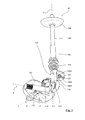
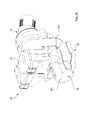
- FIG. 1 shows a combination valve 10 In the illustration parts of the housing and the air ducts have been omitted in order to better represent the functionality.
- the combination valve 10 has a low-pressure exhaust gas recirculation valve 11 and an intake air throttle 12.
- the low-pressure exhaust gas recirculation valve 11 is arranged in an exhaust gas inlet 14.
- the exhaust gas inlet 14 may be connected, for example, to the exhaust tract downstream of the turbine of a turbocharger.
- the low-pressure exhaust gas is removed in a diesel engine after the diesel particulate filter and preferably passed through a low-pressure exhaust gas recirculation cooler to reduce the exhaust gas temperature.
- the low-pressure exhaust gas recirculation valve 11 is in the in FIG. 1 shown embodiment designed as a linearly movable poppet valve. In the position shown, the valve disk is located in the valve seat and thus closes off the exhaust gas inlet 14.
- the intake air throttle 12 has an intake air throttle valve 121 arranged in an intake air passage with an intake air inlet 16, downstream of an air filter (not shown), for example, in the intake air passage.
- an air throttle valve 121 Upon actuation of the intake air throttle 12, the angular position of the intake air throttle valve 121 changes within the intake air passage, thus reducing the effective cross-section within the intake air passage. This results in a partial pressure gradient from the intake air inlet 16 to the outlet 18. This in turn increases the influx of exhaust gas via the exhaust gas inlet 14.
- the supplied exhaust gas strikes the intake air. This is usually followed by an EGR mixer. There, the supplied exhaust gas is mixed with the intake air.
- FIG. 2 shows the kinematic element 100 with parts of intake air throttle 12 and low-pressure exhaust gas recirculation valve 11.
- the kinematics element 100 has a main body 1001, which extends substantially along an axis Y as an elongated cuboid.
- a first cage 110 is attached at a front end of the elongated in the Y direction cuboid.
- the inside of the first cage 110 has essentially the shape of a slot, whose narrow sides are closed by circles and whose diameters correspond to the width of the oblong hole.
- the longitudinal sides of the oblong hole extend essentially parallel to one another.
- the second cage 120 Perpendicular to the expansion plane of the first cage 110, the second cage 120 extends substantially along an axis X.
- the second cage 120 has a substantially cuboidal geometry in the interior.
- the geometry tapers. This is for example in FIG. 3 good to see.
- the cages 110, 120 are arranged substantially at 90 ° to each other. This implies that the engaging in the cages 110, 120 cranks are also offset in its plane of movement by 90 °.
- the drive pin 113 In the first cage 110 engages a drive pin 113 of a drive crank 112 a.
- the drive pin 113 is supported by means of a ball bearing.
- the diameter of the ball bearing drive journal 113 substantially corresponds to the width of the slot of the cage 110.
- the power crank 112 rotates about an axis X and is driven, for example, by a motor (not shown).
- the drive journal 113 describes a circular segment path.
- the drive pin 113 moves within the cage 110 between two end positions and thereby moves the kinematic element 100 linearly along the axis Y. There is no or little play of the drive pin 113 in the direction of the Y axis.
- the intake throttle valve 121 is rotatably mounted about an axis Z and has a driven crank 122.
- An output pin 123 of the output crank 122 engages in the second cage 120 a.
- the second cage 120 sets the output crank 122 in rotation about the axis Z and thus moves the intake air throttle 12 or its intake air throttle valve 121.
- the output crank 122 is coupled to a torsion spring 124.
- the torsion spring 124 embodied here by way of example as a cylindrical torsion spring exerts a rotational force on the output crank 122 in such a way that the output pin 123 bears against the second cage 120.
- a position is shown in which the output pin 123 rests against a first portion 1201 of the second cage 120.
- the first section 1201 is the section 1201 of the second cage 120 along the axis Y in the direction of the first cage 110.
- the low-pressure exhaust gas recirculation valve 11 has a valve rod 130, at whose end facing away from the kinematic element 100 end a valve plate 131 is provided.
- the valve rod 130 is slidably mounted within a sleeve 132.
- the sleeve 132 is fixedly arranged relative to the kinematic element 100 and serves as a guide for the valve rod 130.
- At the end of the valve rod 130, which faces the kinematic element 100 there is a stop for a compression spring 114.
- the compression spring 114 is concentric with the axis Y and arranged to the valve rod 130.
- the compression spring 114 is executed here by way of example as a spherical compression spring to allow a small space requirement and ease of manufacture.
- the compression spring 114 exerts a spring force on the valve rod 130 and thus also on the valve disk 131 along the axis Y in the direction of the kinematic element 100 and thus presses the valve disk 131 in the direction of a valve seat. Valve rod 130 and valve plate 131 thus follow a movement of the kinematic element 100 along the axis Y immediately.
- position of the kinematic element 100 corresponds to a wide opening of the low-pressure exhaust gas recirculation valve 11 and a relatively strong closed position of the intake air throttle 12th
- Both the compression spring 114 and the torsion spring 124 act rectilinearly on the kinematic element 100 and exert a force that pushes it along the axis Y in the direction of the drive crank 112.
- the compression spring 114 is supported on the sleeve 132 from.
- the torsion spring 124 is supported on a housing section, not shown.
- the intake air throttle 12 jammed - for example, by icing or high thermal load - lifts in such a described movement of the kinematic element 100 along the axis Y in the direction of the drive crank 112 of the output pin 123 of the first portion 1201 of the second cage 120th with continued movement of the kinematic element 100 from the second section 1202.
- This idle stroke makes it possible to accelerate the entire mass moved with the kinematic element 100, so that a certain momentum transfer takes place upon impact of the driven pin 123 on the second section 1202 of the second cage 120, so that breakaway can take place from the icing or clamping position of the intake air throttle 12. It is thus possible to exert a considerable breakaway force on the intake air throttle 12 via the drive crank 112.
- the end position of the intake air throttle 12 is already reached. This can be achieved for example by a stop for a movable part of the intake air throttle 12. If the kinematics element 100 then continues its movement, the output pin 123 also lifts off from the first section 1201. The thus resulting idle stroke can be used to ensure that when opening the low-pressure exhaust gas recirculation valve 11 from its closed position initially the intake air throttle 12 remains in its open position. Only after completion of the idle stroke of the output pin 123 contacts the second cage 120 at its first portion 1201 and thus initiates the closing operation of the intake air throttle 12 a.
- FIGS. 4 and 5 an alternative embodiment of a kinematic element 200.
- the basic embodiment is identical to that of the kinematic element 100, so that a description of the structure need not be repeated, but reference is made to the corresponding explanations to the kinematic element 100.
- the kinematic element 200 does not have a closed cage 120. Instead, an abutment driver structure 220 is provided.
- a stop 2201 is arranged with respect to the movement axis Y of the kinematic element 200 with respect to a driver 2202. Between stop 2201 and driver 2202 engages a driven pin 123 of the output crank 122 of the intake air throttle 12 a.
- the output crank 122 is set in rotation about the axis Z and the intake air throttle 12 or its intake air throttle flap 121 is moved.
- a torsion spring 124 exerts a force on the output crank 122, so that in the present embodiment of the kinematic element 200 the output crank 122 or the output pin 123 abuts against the stop 2201.
- the restoring force applied by the torsion spring 124 is not sufficient to move the intake air throttle 12 so that the driven pin 123 abuts against the stop 2201. This can occur, for example, in the case of icing of the intake air throttle 12, in the event of jamming or if the torsion spring 124 breaks.
- the kinematic element 200 has already covered the possible between the stop 2201 and the driver 2202 for the output pin 123 distance, so running the idle stroke.
- the driver 2202 thus meets FIG. 4 after a "swing recovery" on the rigidly connected to the intake air throttle 12 output pin 123 and tears it with, so that the kinematics 200 in the FIG. 5 shown position occupies.
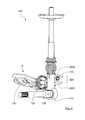
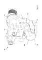
- FIG. 6 shows a perspective view of an intake air throttle 312 according to the invention.
- FIG. 7 is the intake air throttle 312 in an exemplary embodiment of an intake air throttle 20, FIG. 8 integrated in an exemplary embodiment of a combination valve 30.
- Air ducts have been omitted to better represent the shape of the intake air throttle 312.
- FIGS. 7 to 14 are also parts of the housing and parts of the air ducts omitted to represent the functionality can.
- the intake air throttle 20 has an intake air intake passage 16 and an exhaust 18, and is disposed, for example, in the intake air passage after an air cleaner (not shown).
- the intake air throttle 312 has a throttle shaft 3121 provided with a storage surface 3122 of the intake air throttle 312 at one in the FIGS. 6 to 11 upper attachment point 3123 and a lower attachment point 3124 is connected.
- the throttle shaft 3121 is in the FIGS. 6 to 11 is rotatably supported about an axis Z and is driven by a drive 13.
- the airflow facing away from outer surface 3125 of the intake throttle valve 312 has a parallel to the axis Z extending first rib 3126 and a perpendicular to the axis Z extending second rib 3127.
- the basic shape of the storage area 3122 is complex.
- the airflow facing inner surface 3128 is convex, corresponds in part to a cylindrical shape and partially a dome shape. While in the area of the second rib 3127, the storage area 3122 is substantially spherical or dome-shaped, the storage area 3122 extends in the region of the attachment locations 3123, 3124 substantially parallel to one another and into the FIGS. 6 to 11 horizontal.
- the horizontal cross section of the intake air throttle 312 is comparatively small at the attachment points 3123, 3124, while it is greatest in the region of the horizontal second rib 3127.
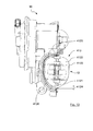
- FIG. 7 the intake air throttle 312 is integrated with an intake air throttle 20 into which FIGS. 8 to 11
- the intake air throttle 312 is shown integrated into a combination valve 30.
- the inner surface 161 of the intake air passage having the intake air inlet 16 is shown partially ripped open. It is in the FIGS. 7 and 8th It will be appreciated that the intake air throttle 312 is located in a cavity 162 of the intake air passage. At the same time, the bearing of the intake air throttle valve 312 in the region of the lower attachment point 3124 in the cavity 162.
- the shaft 3121 of the intake throttle valve 312 is driven in the case of the combination valve 30 by a driven crank 122 of a kinematic element 100 and 200, as already explained above has been.
- the shaft 3121 may be driven directly by the drive 13. Due to the fact that the intake air throttle 312 covers only half of the inner circumference of the intake air passage, the risk of icing is reduced.
- the vertical first rib 3126 in the open position of the intake air throttle 312 is the relevant point at which icing with the inner surface 161 of the flow channel can take place. Compared to the total area of the intake air throttle 312, this area is small and thus the breakaway torque also significantly smaller than in conventional throttle body geometries.
- FIG. 8 While in FIG. 8 the intake throttle valve 312 is shown in the open position, it is located in the FIG. 9 in a partially closed stowage position.
- the Figures 10 and 11 show the stowage position ( FIG. 10 ) and the open position ( FIG. 11 ) from a different perspective. Due to the adapted to the internal geometry of the intake air duct shape of the intake air throttle 312 results in the open position of FIG. 11 a particularly low pressure drop, since only the shaft 3121 protrudes into the air flow. All other parts of the intake air throttle 312, such as bearings or the storage area 3122 itself, are located in the cavity 162 and thus outside of the air flow.
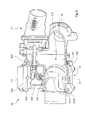
- FIGS. 1 and 8 to 11 show two perspective views of a combination valve according to the invention 10.
- the general structure of the combination valve 10 corresponds to that of the FIGS. 1 and 8 to 11 described combination valves. Identical or comparable features are therefore designated by the same reference numerals. It will be to avoid of repetitions, only the parts of the combination valve 10 which are relevant to the present invention are described. In the representation of the combination valve 10 parts of the housing and the air ducts have been omitted in order to better represent the functionality.
- the combination valve 10 has a low-pressure exhaust gas recirculation valve 11 and an intake air throttle 12.
- the low-pressure exhaust gas recirculation valve 11 is arranged in an exhaust gas inlet channel 14 of the combination valve 10.
- the intake air throttle 12 is disposed in an intake air intake passage having an intake air inlet 16 of the combination valve 10.
- the intake air intake passage is shown cut along its flow direction.
- the intake air throttle 12 has an intake air throttle 412.
- the intake air throttle 412 has a throttle shaft 4121 and a storage surface 4122.
- the storage area 4122 is rotatable about the longitudinal axis Z of the throttle shaft 4121. Upon actuation of the intake air throttle 412, its angular position in the intake air intake passage changes.
- the in the Figures 12 and 13 shown position corresponds to a closed or stowed position in which the intake air throttle valve 412 generates a maximum back pressure in the intake air intake passage.
- a rotated by 90 ° about the longitudinal axis Z position of the storage area 4122 is the intake air throttle 412 in the open position and the generated back pressure is minimal.
- the circumference 4123 of the intake air throttle 412 is adapted in geometry to the geometry of the inner surface 161 of the intake air intake passage. Between the inner surface 161 and the periphery 4123 of the intake air throttle 412, a gap 4124 is provided. In certain embodiments, as in FIG. 13 illustrates that the gap may not be formed uniformly wide over the entire circumference 4123 of the intake throttle valve 412. In an upper region 4125 and in a lower region 4126, the gap is particularly wide, while it is significantly smaller in an intermediate region. Such a division of the gap widths is particularly useful when the combination valve occupies a preferred position in which an ice formation is to be feared.
- This principle of a gap formation between the intake air throttle valve and the inner wall or the inner surface of the surrounding air duct can of course also with the alternative embodiment of the flap shape of FIGS. 6 to 11 or / and with the configuration of the kinematic elements 100, 200 for particularly favorable power transmission for a breakaway of the intake air throttle in Klemmungs- / icing case are combined advantageously.
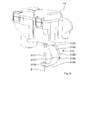
- FIGS. 8 and 9 shown embodiment of a combination valve 30 has a two-stage sealing concept with at least three dynamic seals.
- a first seal 301 is located between the intake air intake passage and a kinematics room 302.
- the movable elements are arranged, which are provided for driving the low-pressure exhaust gas recirculation valve 11 and the intake air throttle 12.
- a kinematics element 100, 200, a driven crank 122 for actuating an intake air throttle valve 121, 312, 412, a drive crank 112 for moving the kinematic element 100, 200 are arranged in the kinematics space 302, as shown by way of example in the previously described figures.
- the first seal 301 is a shaft seal for sealing the kinematics space 302 against the intake air inlet 16 and the flow space between the Intake air inlet 16 and the outlet 18 and is in particular on the throttle shaft, which serves to move the storage area of the intake air throttle attached.
- a second seal 303 seals the kinematics space 302 against the Akturatorraum 304, in which the drive 13 is arranged from.
- a third seal 305 also seals the kinematics chamber 302, but against the region of the low-pressure exhaust gas recirculation valve 11.
- the actuator of the low-pressure exhaust gas recirculation valve 11 may be provided a shaft seal or a rod seal.
- the third seal 305 as a rod seal it may itself be formed in two stages and constructed of a gap seal and a rod seal. Between gap seal and rod seal the storage of the rod can be arranged.
Landscapes
- Engineering & Computer Science (AREA)
- Chemical & Material Sciences (AREA)
- Combustion & Propulsion (AREA)
- Mechanical Engineering (AREA)
- General Engineering & Computer Science (AREA)
- Control Of Throttle Valves Provided In The Intake System Or In The Exhaust System (AREA)
Abstract
Die Erfindung betrifft eine Ansaugluftdrossel für einen Verbrennungsmotor, mit einem Ansauglufteinlass sowie einem Auslass, wobei zwischen dem Ansauglufteinlass und dem Auslass eine zwischen einer Offenposition und einer Stauposition bewegbare Ansaugluftdrosselklappe für die Steuerung eines Druckgefälles eines Fluidstroms von dem Ansauglufteinlass zu dem Auslass angeordnet ist, wobei die Ansaugluftdrossel zwischen dem Ansauglufteinlass und dem Auslass eine Strömungskanalinnengeometrie aufweist und die Grundform der Ansaugluftdrosselklappe zumindest teilweise einem Ausschnitt der Strömungskanalinnengeometrie der Ansaugluftdrossel entspricht.The invention relates to an intake throttle for an internal combustion engine, having an intake air inlet and an outlet, wherein between the intake air inlet and the outlet a movable between an open position and a stowed position Ansaugluftdrosselklappe for controlling a pressure gradient of a fluid flow from the intake air inlet is arranged to the outlet Intake air throttle between the intake air inlet and the outlet has a flow channel inner geometry and the basic shape of the intake air throttle corresponds at least partially to a section of the flow channel inner geometry of the intake air throttle.
Description
Die vorliegende Erfindung betrifft eine Ansaugluftdrossel für einen Verbrennungsmotor und ein Kombiventil mit Niederdruck-Abgasrückführungsventil und einer solchen Ansaugluftdrossel.The present invention relates to an intake air throttle for an internal combustion engine and a combination valve with low-pressure exhaust gas recirculation valve and such an intake air throttle.
Um die NOx-Emission von Dieselmotoren und den CO2-Ausstoß von Ottomotoren zu reduzieren, ist es ein Ziel, die Verbrennungstemperatur im Brennraum zu senken. Zu diesem Zweck wird der dem Verbrennungsmotor zugeführten Reinluft Abgas zugegeben. Dies führt im Falle von Dieselmotoren zu einer Absenkung der Reaktiongeschwindigkeit und damit der Verbrennungstemperatur. Bei Ottomotoren können Ladungswechselverluste vermieden und ebenfalls NOx-Emissionen verringert werden. Man unterscheidet bei der Abgasrückführung (AGR) zwischen einer Hochdruck-AGR und einer Niederdruck-AGR. Bei der Hochdruck-AGR erfolgt die Entnahme des Abgases vor der Turbine eines Turboladers. Das entnommene Abgas wird stromabwärts von Verdichter und Ansaugluftdrossel eingeleitet. Bei der Niederdruck-AGR wird das zu entnehmende Abgas nach der Abgasnachbehandlung entnommen und vor einem Turbolader zugemischt.In order to reduce the NO x emissions of diesel engines and the CO 2 emissions of gasoline engines, it is a goal to lower the combustion temperature in the combustion chamber. For this purpose, the pure air supplied to the internal combustion engine exhaust gas is added. In the case of diesel engines, this leads to a lowering of the reaction speed and thus of the combustion temperature. In gasoline engines, charge cycle losses can be avoided and also NO x emissions can be reduced. A distinction is made in the exhaust gas recirculation (EGR) between a high-pressure EGR and a low-pressure EGR. In the case of the high-pressure EGR, the removal of the exhaust gas takes place in front of the turbine of a turbocharger. The extracted exhaust gas is introduced downstream of the compressor and the intake air throttle. In the case of the low-pressure EGR, the exhaust gas to be taken off is taken off after the exhaust gas aftertreatment and admixed in front of a turbocharger.
Die vorliegende Erfindung befasst sich mit der Niederdruck-AGR.The present invention is concerned with low pressure EGR.
Es ist im Stand der Technik bekannt, ein Niederdruck-AGR-Ventil und eine Ansaugluftdrossel baulich so zu kombinieren, dass beide Steuerelemente zusammen wirken. Wird eine größere Menge an AGR-Gas benötigt, wird die Ansaugluftdrossel schrittweise geschlossen. Das Verringern des wirksamen Querschnitts im Ansaugtrakt durch ein Schließen der Ansaugluftdrossel erzeugt lokal einen partiellen Unterdruck und ermöglicht so eine größere Entnahme beziehungsweise Zuführung von Abgas.It is known in the art to structurally combine a low pressure EGR valve and an intake throttle so that both controls operate together. If a larger amount of EGR gas is required, the intake throttle is gradually closed. Reducing the effective cross-section in the intake tract by closing the intake air throttle locally generates a partial negative pressure and thus allows greater removal or supply of exhaust gas.
Um eine möglichst hohe Effizienz des Verbrennungsmotors zu gewährleisten, wird herkömmlicherweise die Ansaugluftdrossel so gestaltet, dass sie einerseits einen hohen Staudruck erzeugen kann und andererseits in der geöffneten Stellung geringe Druckverluste erzeugt. Bei den herkömmlichen Ansaugluftdrosseln tritt immer wieder das Problem auf, dass die Ansaugluftdrossel in der geöffneten Stellung vereist und dann bis zu einem Auftauen unbeweglich in der geöffneten Stellung verbleibt. Die auf die Ansaugluftdrossel ausübbaren Kräfte reichen in der Regel nicht für ein Losbrechen der Ansaugluftdrossel.To ensure the highest possible efficiency of the internal combustion engine, conventionally, the intake throttle is designed so that on the one hand can generate a high back pressure and on the other hand generates low pressure losses in the open position. In the conventional intake air throttles, the problem repeatedly arises that the intake air throttle ices in the open position and then remains immovable in the open position until thawing. The exercisable on the intake air throttle forces are usually not sufficient for a breakaway of the intake air throttle.
Der vorliegenden Erfindung liegt die Aufgabe zugrunde, eine Ansaugluftdrossel sowie ein Kombiventil mit einer Ansaugluftdrossel mit minimalem Druckverlust und verbesserten Vereisungseigenschaften anzugeben.The present invention has for its object to provide an intake air throttle and a combination valve with an intake air throttle with minimal pressure loss and improved icing.
Eine die erfindungsgemäße Aufgabe lösende Ansaugluftdrossel für einen Verbrennungsmotor weist einen Ansauglufteinlass, einen Auslass und zwischen dem Ansauglufteinlass und dem Auslass eine zwischen einer Offenposition und einer Stauposition bewegbare, insbesondere drehbare, Ansaugluftdrosselklappe für die Steuerung eines Druckgefälles eines Fluidstroms von dem Ansauglufteinlass zu dem Auslass auf.An intake air throttle for an internal combustion engine which achieves the object according to the invention has an intake air inlet, an outlet and between the intake air inlet and the outlet a, in particular rotatable, intake air throttle valve movable between an open position and a stowed position for controlling a pressure gradient of a fluid flow from the intake air inlet to the outlet.
Erfindungsgemäß weist die Ansaugluftdrossel zwischen dem Ansauglufteinlass und dem Auslass eine Strömungskanalinnengeometrie auf, wobei die Grundform der Ansaugluftdrosselklappe zumindest teilweise einem Ausschnitt der Strömungskanalinnengeometrie der Ansaugluftdrossel entspricht. Durch das Anformen der Ansaugluftdrosselklappe an die Strömungskanalinnengeometrie kann einerseits in der Offenposition der durch die Ansaugluftdrosselklappe bewirkte Staudruck minimiert werden. Gleichzeitig bewirkt diese Ausgestaltung, dass die Ansaugluftdrosselklappe lediglich einem Teil der Innenfläche des Strömungskanals in der Offenstellung so nahe ist, dass eine Vereisung mit diesem erfolgen kann. Insgesamt wird somit die Losbrechkraft im Vereisungsfall reduziert, da die mit der Innenfläche des Strömungskanals vereiste Fläche verkleinert ist.According to the invention, the intake air throttle between the intake air inlet and the outlet has a flow channel internal geometry, wherein the basic shape of the intake air throttle valve at least partially corresponds to a section of the flow channel internal geometry of the intake air throttle. By molding the intake throttle valve to the flow passage internal geometry, on the one hand in the open position the dynamic pressure caused by the intake throttle valve can be minimized. At the same time, this embodiment causes the intake throttle valve to be so close to only a part of the inner surface of the flow passage in the open position that icing can occur therewith. Overall, therefore, the breakaway force is reduced in the event of icing, since the iced with the inner surface of the flow channel surface is reduced.
Eine Ausführungsform der Erfindung sieht vor, dass die Strömungskanalinnengeometrie im Wesentlichen zylindrisch ist und die Grundform der Ansaugluftdrosselklappe zumindest teilweise ein Zylindermantelflächenausschnitt ist. Insbesondere kann vorgesehen sein, dass die Grundform der Ansaugluftdrosselklappe zumindest teilweise einen Mantelflächenabschnitt eines Halbzylinders darstellt. Generell ist es selbstverständlich möglich, die Strömungskanalinnengeometrie innerhalb gewisser Grenzen frei zu gestalten. Entsprechend kann auch die Grundform der Ansaugluftdrosselklappe entsprechend frei gestaltet sein.An embodiment of the invention provides that the flow channel inner geometry is substantially cylindrical and the basic shape of the intake air throttle valve at least partially a cylinder surface cutout is. In particular, it can be provided that the basic shape of the intake air throttle valve at least partially represents a lateral surface section of a half cylinder. In general, it is of course possible to make the flow channel interior geometry within certain limits freely. Accordingly, the basic shape of the intake throttle valve can be designed according to free.
Bei einer einem Halbzylinder ähnlichen Ausgestaltung der Ansaugluftdrosselklappe kann die Lagerung der Ansaugluftdrosselklappe, insbesondere für eine Welle zur Drehung der Ansaugluftdrosselklappe, in einem Bereich senkrecht zu der Achse des Halbzylinders vorgesehen sein.In a configuration of the intake air throttle valve similar to a half cylinder, the bearing of the intake air throttle valve, in particular for a shaft for rotating the intake air throttle valve, may be provided in a region perpendicular to the axis of the half cylinder.
Als Alternative zu der halbzylinderförmigen Ausgestaltung kann vorgesehen sein, dass die Strömungskanalinnengeometrie und/oder die Grundform der Ansaugluftdrosselklappe zumindest teilweise kalottenförmig sind. Eine kugel- oder kalottenförmige Form ist der vorgesehenen Drehbewegung der Ansaugluftdrosselklappe anpassbar.As an alternative to the semi-cylindrical configuration, it can be provided that the flow channel internal geometry and / or the basic shape of the intake air throttle valve are at least partially dome-shaped. A spherical or dome-shaped shape is adaptable to the intended rotational movement of the intake air throttle.
Eine vorteilhafte Ausführungsform der Erfindung sieht vor, dass die Ansaugluftdrosselklappe in der Offenposition eine dem Fluidstroms zugewandte Innengeometrie und eine dem Fluidstroms abgewandte Außengeometrie aufweist, wobei die Außengeometrie zumindest eine Rippe, vorzugsweise zwei senkrecht zueinander angeordnete Rippen aufweist. Die Rippe kann zum einen eine Verstärkung der Flächenstabilität der Ansaugluftdrosselklappe darstellen. Zum anderen kann die Rippe in der Offenposition die Fläche minimieren, die zwischen der Ansaugluftdrosselklappe und der inneren Oberfläche des Strömungskanals verreist wird. Die sich bei Unterschreiten des Taupunktes niederschlagende Feuchtigkeit bewirkt bei einem Unterschreiten des Gefrierpunkts nur dann ein Verklemmen der Ansaugluftdrosselklappe, wenn die sich bildende Eisschicht die Ansaugluftdrosselklappe mit der Innenfläche des Strömungskanals verbindet. Wenn also der Innenfläche des Strömungskanals die Oberfläche einer Rippe am nächsten ist, wird lediglich die Rippe mit der Innenfläche des Strömungskanals verreisen. Der Rest der Oberfläche der Ansaugluftdrosselklappe bleibt frei und dass Losbrechmoment nach einem Vereisen ist verringert.An advantageous embodiment of the invention provides that, in the open position, the intake air throttle valve has an inner geometry facing the fluid flow and an outer geometry facing away from the fluid flow, the outer geometry having at least one rib, preferably two ribs arranged perpendicular to one another. On the one hand, the rib can represent an increase in the surface stability of the intake air throttle valve. On the other hand, the rib in the open position can minimize the area traveled between the intake air throttle and the inner surface of the flow channel. The precipitation when falling below the dew point moisture causes a fall below the freezing point only jamming of the intake air throttle valve when the forming ice layer connects the intake air throttle with the inner surface of the flow channel. Thus, if the inner surface of the flow channel is closest to the surface of a rib, only the rib will travel with the inner surface of the flow channel. The rest of the surface of the intake air throttle remains free and the breakaway torque after icing is reduced.
Eine besonders bevorzugte Ausführungsform der Erfindung sieht vor, dass im Bereich der Ansaugluftdrosselklappe in der Strömungskanalinnengeometrie eine Kavität zur zumindest teilweisen Aufnahme der Ansaugluftdrosselklappe vorgesehen ist. Die Kavität kann so ausgebildet sein, dass die Kavität in der Offenposition der Ansaugluftdrosselklappe diese so aufnimmt, dass in den Strömungskanal nur noch lediglich die zur Bewegung der Ansaugluftdrosselklappe notwendige Mechanik, wie beispielsweise eine Welle, ragt. Auf diese Weise ist der Druckverlust in der Offenposition der Ansaugluftdrosselklappe minimal.A particularly preferred embodiment of the invention provides that a cavity for at least partially receiving the intake air throttle valve is provided in the region of the intake air throttle flap in the flow channel internal geometry. The cavity can be designed such that the cavity in the open position of the intake air throttle valve receives it so that only the mechanism necessary for moving the intake air throttle flap, such as a shaft, protrudes into the flow passage. In this way, the pressure loss in the open position of the intake air throttle is minimal.
Dieser Erfindungsgedanke kann auch in einem Kombiventil für einen Verbrennungsmotor seinen Niederschlag finden. Das erfindungsgemäße Kombiventil weist ein Niederdruck-Abgasrückführungsventil und eine erfindungsgemäße Ansaugluftdrossel auf. Dabei kann insbesondere vorgesehen sein, dass das Kombiventil einen Abgaseinlass und einen Ansauglufteinlass aufweist, wobei zwischen dem Abgaseinlass und dem Auslass das Niederdruck-Abgasrückführungsventil und zwischen dem Ansauglufteinlass und dem Auslass die Ansaugluftdrosselklappe angeordnet sind, wobei das Kombiventil ein Kinematikelement aufweist, das gemeinsam das Niederdruck-Abgasrückführungsventil und die Ansaugluftdrossel bzw. die Drosselklappe betätigt. Dabei kann das Kinematikelement vorzugsweise einen Käfig, einen Anschlag und einen Mitnehmer aufweisen, wobei in den Käfig ein Antriebselement, insbesondere eine Antriebskurbel zur Bewegung des Kinematikelements sowie des Niederdruck-Abgasrückführungsventil eingreift und zwischen den Anschlag und den Mitnehmer ein Abtriebselement, insbesondere eine Abtriebskurbel zur Bewegung der Ansaugluftdrossel eingreift. Die gemeinsame Bewegung des Niederdruck-Abgasrückführungsventils und der Ansaugluftdrossel kann vorteilhaft bei einem Losbrechen einer vereisten Ansaugluftdrossel sein.This idea of the invention can also be found in a combination valve for an internal combustion engine. The combination valve according to the invention has a low-pressure exhaust gas recirculation valve and an intake air throttle according to the invention. In this case, it can be provided, in particular, that the combination valve has an exhaust gas inlet and an intake air inlet, wherein the low-pressure exhaust gas recirculation valve is arranged between the exhaust gas inlet and the outlet, and the intake air throttle valve between the intake air inlet and the outlet, wherein the combined valve has a kinematics element which together the low pressure Exhaust gas recirculation valve and the intake air throttle or the throttle operated. In this case, the kinematic element preferably has a cage, a stop and a driver, wherein in the cage a drive element, in particular a drive crank for moving the kinematic element and the low pressure exhaust gas recirculation valve engages and between the stop and the driver an output element, in particular a driven crank for movement the intake air throttle engages. The joint movement of the low-pressure exhaust gas recirculation valve and the intake air throttle may be advantageous in a breakaway of an icy intake air throttle.
Es wird nun die Erfindung anhand der beigefügten Zeichnungen erläutert. Es zeigen:
- Figur 1
- eine perspektivische Teilansicht einer erfindungsgemäßen Ausführungsform eines Kombiventils;
- Figur 2
- eine perspektivische Ansicht eines Kinematikelements des in
Figur 1 gezeigten Kombiventils; - Figur 3
- eine weitere perspektivische Ansicht des Kinematikelements der
Figur 2 ; - Figur 4
- eine perspektivische Ansicht einer alternativen Ausführungsform eines Kinematikelements der
Figur 2 in einer ersten Stellung; - Figur 5
- das Kinematikelement der
Figur 4 in einer zweiten Stellung; - Figur 6
- eine perspektivische Ansicht einer alternativen Ausführungsform einer Ansaugluftdrosselklappe, insbesondere für ein Kombiventil;
- Figur 7
- die Ansaugluftdrosselklappe der
Figur 6 in einer beispielhaften Ausführungsform einer Ansaugluftdrossel; - Figur 8
- die Ansaugluftdrosselklappe der
Figur 6 in einer beispielhaften Ausführungsform eines Kombiventils; - Figur 9
- die beispielhafte Ausführungsform des Kombiventils der
Figur 8 mit einer anderen Stellung der Ansaugluftdrosselklappe; Figur 10- eine perspektivische Ansicht des Kombiventils der
Figur 8 mit der Ansaugluftdrosselklappe in einer Stauposition; Figur 11- die
Ansicht der Figur 10 mit der Ansaugluftdrosselklappe in einer Offenposition; Figur 12- eine erste perspektivische Ansicht eines erfindungsgemäßen Kombiventils in einer seitlichen Aufrissdarstellung;
Figur 13- eine zweite perspektivische Ansicht des Kombiventils der
Figur 12
- FIG. 1
- a partial perspective view of an embodiment of a combination valve according to the invention;
- FIG. 2
- a perspective view of a kinematic element of in
FIG. 1 shown combination valve; - FIG. 3
- another perspective view of the kinematics of the
FIG. 2 ; - FIG. 4
- a perspective view of an alternative embodiment of a kinematic element of
FIG. 2 in a first position; - FIG. 5
- the kinematic element of
FIG. 4 in a second position; - FIG. 6
- a perspective view of an alternative embodiment of an intake air throttle, in particular for a combination valve;
- FIG. 7
- the intake throttle valve
FIG. 6 in an exemplary embodiment of an intake air throttle; - FIG. 8
- the intake throttle valve
FIG. 6 in an exemplary embodiment of a combination valve; - FIG. 9
- the exemplary embodiment of the combination valve of
FIG. 8 with another position of the intake throttle valve; - FIG. 10
- a perspective view of the combination valve of
FIG. 8 with the intake air throttle in a stowed position; - FIG. 11
- the view of
FIG. 10 with the intake air throttle in an open position; - FIG. 12
- a first perspective view of a combination valve according to the invention in a side elevational view;
- FIG. 13
- a second perspective view of the combination valve of
FIG. 12 ,
Das Niederdruck-Abgasrückführungsventil 11 ist in einem Abgaseinlass 14 angeordnet. Der Abgaseinlass 14 kann beispielsweise mit dem der Turbine eines Turboladers nachgeordneten Abgastrakt verbunden sein. Beispielsweise wird die Niederdruck-Abgasluft bei einem Dieselmotor nach dem Dieselpartikelfilter entnommen und vorzugsweise noch durch einen Niederdruck-Abgasrückführungs-Kühler zur Reduzierung der Abgastemperatur geleitet. Das Niederdruck-Abgasrückführungsventil 11 ist in der in
Die Ansaugluftdrossel 12 weist eine in einem Ansaugluftkanal mit einem Ansauglufteinlass 16 angeordnete Ansaugluftdrosselklappe 121 auf, beispielsweise im Ansauglufttrakt einem Luftfilter (nicht dargestellt) nachgeordnet. Bei einer Betätigung der Ansaugluftdrossel 12 verändert sich die Winkelstellung der Ansaugluftdrosselklappe 121 innerhalb des Ansaugluftkanals und verringert so den wirksamen Querschnitt innerhalb des Ansaugluftkanals. Es entsteht ein partielles Druckgefälle vom Ansauglufteinlass 16 zum Auslass 18. Dies erhöht wiederum den Zustrom von Abgas über den Abgaseinlass 14. Im Auslass 18 trifft das zugeführte Abgas auf die Ansaugluft. Es schließt sich in der Regel ein AGR-Mischer an. Dort wird das zugeführte Abgas mit der Ansaugluft gemischt.The
Das Kinematikelement 100 weist einen Grundkörper 1001 auf, der sich im Wesentlichen entlang einer Achse Y als langgestreckter Quader erstreckt. An einem stirnseitigen Ende des in Y-Richtung langgestreckten Quaders ist ein erster Käfig 110 angebracht. Die Innenseite des ersten Käfigs 110 besitzt im Wesentlichen die Form eines Langlochs, dessen schmale Seiten durch Kreise abgeschlossen sind und deren Durchmesser der Breite des Langlochs entsprechen. Die Längsseiten des Langlochs verlaufen im Wesentlichen parallel zueinander Senkrecht zu der Ausdehnungsebene des ersten Käfigs 110 erstreckt sich der zweite Käfig 120, im Wesentlichen entlang einer Achse X. Der zweite Käfig 120 besitzt im Inneren eine im Wesentlichen quaderförmige Geometrie. An der dem Grundkörper 1001 des Kinematikelements 100 abgewandten Seite des Käfigs 120 verjüngt sich die Geometrie. Dies ist beispielsweise in
Die Käfige 110, 120 sind im Wesentlichen im 90° Winkel zueinander angeordnet. Dies bedingt, dass die in die Käfige 110, 120 eingreifenden Kurbeln in ihrer Bewegungsebene ebenfalls um 90° versetzt sind.The
In den ersten Käfig 110 greift ein Antriebszapfen 113 einer Antriebskurbel 112 ein. Der Antriebszapfen 113 ist mittels einer Kugellagerung gelagert. Der Durchmesser des Antriebszapfens 113 mit Kugellagerung entspricht im Wesentlichen der Breite des Langlochs des Käfigs 110. Die Antriebskurbel 112 dreht sich um eine Achse X und wird beispielsweise durch einen Motor (nicht dargestellt) angetrieben. Bei der Rotation der Antriebskurbel 112 um die Achse X beschreibt der Antriebszapfen 113 eine Kreissegmentbahn. Dabei bewegt sich der Antriebszapfen 113 innerhalb des Käfigs 110 zwischen zwei Endpositionen und bewegt dabei das Kinematikelement 100 linear entlang der Achse Y. Dabei ist kein oder wenig Spiel des Antriebszapfens 113 in Richtung der Achse Y vorgesehen.In the
Die Ansaugluftdrosselklappe 121 ist um eine Achse Z drehbar gelagert und weist eine Abtriebskurbel 122 auf. Ein Abtriebszapfen 123 der Abtriebskurbel 122 greift in den zweiten Käfig 120 ein. Bei der linearen Bewegung des Kinematikelements 100 versetzt der zweite Käfig 120 die Abtriebskurbel 122 in eine Drehung um die Achse Z und bewegt damit die Ansaugluftdrossel 12 beziehungsweise deren Ansaugluftdrosselklappe 121. Die Abtriebskurbel 122 ist mit einer Drehfeder 124 gekoppelt. Die hier beispielhaft als zylindrische Torsionsfeder ausgebildete Drehfeder 124 übt eine Drehkraft auf die Abtriebskurbel 122 dergestalt aus, dass der Abtriebszapfen 123 an dem zweiten Käfig 120 anliegt. In der
Das Niederdruck-Abgasrückführungsventil 11 weist eine Ventilstange 130 auf, an deren von dem Kinematikelement 100 wegweisenden Ende ein Ventilteller 131 vorgesehen ist. Die Ventilstange 130 ist innerhalb einer Hülse 132 verschiebbar gelagert. Die Hülse 132 ist ortsfest relativ zu dem Kinematikelement 100 angeordnet und dient als Führung für die Ventilstange 130. An dem Ende der Ventilstange 130, das dem Kinematikelement 100 zugewandt ist, befindet sich ein Anschlag für eine Druckfeder 114. Die Druckfeder 114 ist konzentrisch zur Achse Y und zur Ventilstange 130 angeordnet. Die Druckfeder 114 ist hier beispielhaft als sphärische Druckfeder ausgeführt, um einen geringen Bauraumbedarf und eine leichte Herstellbarkeit zu ermöglichen. Die Druckfeder 114 übt eine Federkraft auf die Ventilstange 130 und damit auch auf den Ventilteller 131 entlang der Achse Y in Richtung des Kinematikelements 100 aus und drückt somit den Ventilteller 131 in Richtung eines Ventilsitzes. Ventilstange 130 und Ventilteller 131 folgen somit einer Bewegung des Kinematikelements 100 entlang der Achse Y unmittelbar.The low-pressure exhaust
Die in
Sowohl die Druckfeder 114 als auch die Drehfeder 124 wirken gleichgerichtet auf das Kinematikelement 100 und üben eine Kraft aus, die es entlang der Achse Y in Richtung Antriebskurbel 112 drückt. Die Druckfeder 114 stützt sich dabei an der Hülse 132 ab. Die Drehfeder 124 stützt sich an einem nicht gezeigten Gehäuseabschnitt ab. Das Vorsehen zweier unabhängiger Federkräfte, die auf zwei verschiedene kinematische Wege auf das Kinematikelement 100 einwirken, stellt ein Sicherheitsmerkmal dar. Des Weiteren erlaubt diese Anordnung eine deutliche Reduzierung des Bewegungsspiels und reduziert die Toleranzkette innerhalb der Anordnung substantiell.Both the
Bei einer Bewegung des Kinematikelements 100 entlang der Achse Y in Richtung der Antriebskurbel 112 folgt der Abtriebszapfen 123 dem zweiten Käfig 120 und liegt dabei an dem ersten Abschnitt 1201 an, da die Drehfeder 124 eine entsprechende Kraft auf die Abtriebskurbel 122 ausübt. Folglich bewegt sich die Ansaugluftdrossel 12 in Richtung ihrer Offenstellung. Gleichzeitig drückt die Druckfeder 114 die Ventilstange 130 entlang der Achse Y in Richtung der Antriebskurbel 112. Der Ventilteller 131 des Niederdruck-Abgasrückführungsventils 11 bewegt sich folglich in Richtung seiner Schließstellung.Upon movement of the
Ist aufgrund bestimmter Umstände die Ansaugluftdrossel 12 verklemmt - beispielsweise durch eine Vereisung oder eine hohe thermische Belastung - hebt sich bei einer derartigen beschriebenen Bewegung des Kinematikelements 100 entlang der Achse Y in Richtung der Antriebskurbel 112 der Abtriebszapfen 123 von dem ersten Abschnitt 1201 des zweiten Käfigs 120 ab und wird bei fortgesetzter Bewegung des Kinematikelements 100 von dem zweiten Abschnitt 1202 mitgenommen. Dieser Leerhub ermöglicht ein Beschleunigen der gesamten mit dem Kinematikelement 100 bewegten Masse, sodass beim Auftreffen des Abtriebszapfens 123 auf den zweiten Abschnitt 1202 des zweiten Käfigs 120 ein gewisser Bewegungsimpulsübertrag stattfindet und so ein Losbrechen aus der Vereisungs- beziehungsweise Verklemmungsposition der Ansaugluftdrossel 12 stattfinden kann. Es ist somit möglich, über die Antriebskurbel 112 eine beträchtliche Losbrechkraft auf die Ansaugluftdrossel 12 auszuüben.If due to certain circumstances, the
Des Weiteren kann vorgesehen sein, dass bevor das Kinematikelement 100 seinen unteren Endpunkt der Bewegung erreicht, bereits die Endstellung der Ansaugluftdrossel 12 erreicht wird. Dies kann beispielsweise durch einen Anschlag für ein bewegliches Teil der Ansaugluftdrossel 12 erreicht werden. Setzt das Kinematikelement 100 dann seine Bewegung fort, hebt sich ebenfalls der Abtriebszapfen 123 von dem ersten Abschnitt 1201 ab. Der sich so ergebende Leerhub kann dazu benützt werden, dass bei dem Öffnen des Niederdruck-Abgasrückführventils 11 aus seiner Schließstellung zunächst die Ansaugluftdrossel 12 in ihrer Offenstellung verharrt. Erst nach Beendigung des Leerhubs kontaktiert der Abtriebszapfen 123 den zweiten Käfig 120 an seinem ersten Abschnitt 1201 und leitet damit den Schließvorgang der Ansaugluftdrossel 12 ein.Furthermore, it can be provided that, before the
Im Unterschied zu der in den
In den
Es wird zunächst auf die Ansaugluftdrosselklappe 312, gezeigt in
Die Ansaugluftdrossel 20 weist einen Ansauglufteinlasskanal 16 und einen Auslass 18 auf und ist beispielsweise im Ansauglufttrakt nach einem Luftfilter (nicht dargestellt) angeordnet. Die Ansaugluftdrosselklappe 312 weist eine Drosselklappenwelle 3121 auf, die mit einer Staufläche 3122 der Ansaugluftdrosselklappe 312 an einer in den
In
Während in
Die
Das Kombiventil 10 weist ein Niederdruck-Abgasrückführungsventil 11 und eine Ansaugluftdrossel 12 auf. Das Niederdruck-Abgasrückführungsventil 11 ist in einem Abgaseinlasskanal 14 des Kombiventils 10 angeordnet. Die Ansaugluftdrossel 12 ist in einem Ansauglufteinlasskanal mit einem Ansauglufteinlass 16 des Kombiventils 10 angeordnet. Der Ansauglufteinlasskanal ist entlang seiner Durchströmungsrichtung geschnitten dargestellt. Die Ansaugluftdrossel 12 weist eine Ansaugluftdrosselklappe 412 auf. Die Ansaugluftdrosselklappe 412 weist eine Drosselklappenwelle 4121 sowie eine Staufläche 4122 auf. Die Staufläche 4122 ist um die Längsachse Z der Drosselklappenwelle 4121 drehbar. Bei einer Betätigung der Ansaugluftdrosselklappe 412 verändert sich ihre Winkelstellung in dem Ansauglufteinlasskanal. Die in den
Der Umfang 4123 der Ansaugluftdrosselklappe 412 ist in seiner Geometrie der Geometrie der Innenfläche 161 des Ansauglufteinlasskanals angepasst. Zwischen der Innenfläche 161 und dem Umfang 4123 der Ansaugluftdrosselklappe 412 ist ein Spalt 4124 vorgesehen. Dabei kann bei bestimmten Ausführungsformen, wie in
Dieses Prinzip eines Spaltausbildung zwischen der Ansaugluftdrosselklappe und der Innenwand beziehungsweise der Innenfläche des umgebenden Luftkanals kann selbstverständlich auch mit der alternativen Ausführungsform der Klappenform der
Die in den
Eine erste Dichtung 301 befindet sich zwischen dem Ansauglufteinlasskanal und einem Kinematikraum 302.A
In dem Kinematikraum 302 sind die beweglichen Elemente angeordnet, die zur Ansteuerung des Niederdruck-Abgasrückführungsventils 11 und der Ansaugluftdrossel 12 vorgesehen sind. Insbesondere sind in dem Kinematikraum 302 ein Kinematikelement 100, 200, eine Abtriebskurbel 122 zur Betätigung einer Ansaugluftdrosselklappe 121, 312, 412, eine Antriebskurbel 112 zur Bewegung des Kinematikelements 100, 200 angeordnet, wie sie in den vorhergehend beschriebenen Figuren exemplarisch dargestellt sind.In the
Die erste Dichtung 301 ist eine Wellendichtung zur Abdichtung des Kinematikraums 302 gegen den Ansauglufteinlass 16 beziehungsweise den Strömungsraum zwischen dem Ansauglufteinlass 16 und dem Auslass 18 und ist insbesondere an der Drosselklappenwelle, die zur Bewegung der Staufläche der Ansaugluftdrosselklappe dient, angebracht.The
Eine zweite Dichtung 303 dichtet den Kinematikraum 302 gegen den Akturatorraum 304, in welchem der Antrieb 13 angeordnet ist, ab.A
Eine dritte Dichtung 305 dichtet ebenfalls den Kinematikraum 302 ab, jedoch gegen den Bereich des Niederdruck-Abgasrückführungsventils 11. Je nach Ausführung des Betätigungselements des Niederdruck-Abgasrückführungsventils 11 kann eine Wellendichtung oder eine Stangendichtung vorgesehen sein. Bei einer Ausbildung der dritten Dichtung 305 als Stangendichtung kann diese selbst zweistufig ausgebildet sein und aus einer Spaltdichtung und einer Stangendichtung aufgebaut sein. Zwischen Spaltdichtung und Stangendichtung kann die Lagerung der Stange angeordnet sein.A
Claims (10)
einem Ansauglufteinlass (16) sowie
einem Auslass (18), wobei
zwischen dem Ansauglufteinlass (16) und dem Auslass (18) eine zwischen einer Offenposition und einer Stauposition bewegbare Ansaugluftdrosselklappe (121, 312, 412) für die Steuerung eines Druckgefälles eines Fluidstroms von dem Ansauglufteinlass (16) zu dem Auslass (18) angeordnet ist,
wobei die Ansaugluftdrossel (12, 20) zwischen dem Ansauglufteinlass (16) und dem Auslass (18) eine Strömungskanalinnengeometrie aufweist und eine Grundform der Ansaugluftdrosselklappe (121, 312, 412) zumindest teilweise einem Ausschnitt der Strömungskanalinnengeometrie der Ansaugluftdrossel (12, 20) entspricht.Intake air throttle (12, 20) for an internal combustion engine, with
an intake air inlet (16) as well
an outlet (18), wherein
between the intake air inlet (16) and the outlet (18) is disposed an intake air throttle (121, 312, 412) movable between an open position and a stowed position for controlling a pressure gradient of a fluid flow from the intake air inlet (16) to the outlet (18);
wherein the intake air throttle (12, 20) has a flow channel internal geometry between the intake air inlet (16) and the outlet (18) and a basic shape of the intake air throttle (121, 312, 412) at least partially corresponds to a section of the flow channel internal geometry of the intake air throttle (12, 20).
einem Abgaseinlass (14), wobei
zwischen dem Abgaseinlass (14) und dem Auslass (18) das Niederdruck-Abgasrückführungsventil (11) angeordnet ist,
wobei das Kombiventil (10, 30) ein Kinematikelement (100, 200) aufweist, das gemeinsam das Niederdruck-Abgasrückführungsventil (11) und die Ansaugluftdrossel (12, 20) betätigt.Combination valve (10, 30) according to claim 9, with
an exhaust gas inlet (14), wherein
between the exhaust inlet (14) and the outlet (18), the low-pressure exhaust gas recirculation valve (11) is arranged,
wherein the combination valve (10, 30) comprises a kinematic element (100, 200) which operates in common the low-pressure exhaust gas recirculation valve (11) and the intake air throttle (12, 20).
Priority Applications (1)
| Application Number | Priority Date | Filing Date | Title |
|---|---|---|---|
| EP15290116.1A EP3093476A1 (en) | 2015-04-30 | 2015-04-30 | Intake air throttle for a combustion engine and combination valve with low pressure exhaust gas recirculation valve and intake air throttle |
Applications Claiming Priority (1)
| Application Number | Priority Date | Filing Date | Title |
|---|---|---|---|
| EP15290116.1A EP3093476A1 (en) | 2015-04-30 | 2015-04-30 | Intake air throttle for a combustion engine and combination valve with low pressure exhaust gas recirculation valve and intake air throttle |
Publications (1)
| Publication Number | Publication Date |
|---|---|
| EP3093476A1 true EP3093476A1 (en) | 2016-11-16 |
Family
ID=53180671
Family Applications (1)
| Application Number | Title | Priority Date | Filing Date |
|---|---|---|---|
| EP15290116.1A Withdrawn EP3093476A1 (en) | 2015-04-30 | 2015-04-30 | Intake air throttle for a combustion engine and combination valve with low pressure exhaust gas recirculation valve and intake air throttle |
Country Status (1)
| Country | Link |
|---|---|
| EP (1) | EP3093476A1 (en) |
Citations (3)
| Publication number | Priority date | Publication date | Assignee | Title |
|---|---|---|---|---|
| US6367773B1 (en) * | 1999-10-07 | 2002-04-09 | Aisan Kogyo Kabushiki Kaisha | Throttle valve control device |
| EP1947312A1 (en) * | 2007-01-16 | 2008-07-23 | Hitachi, Ltd. | Butterfly valve device |
| US20120145134A1 (en) * | 2010-12-09 | 2012-06-14 | Denso Corporation | Exhaust gas recirculation system |
-
2015
- 2015-04-30 EP EP15290116.1A patent/EP3093476A1/en not_active Withdrawn
Patent Citations (3)
| Publication number | Priority date | Publication date | Assignee | Title |
|---|---|---|---|---|
| US6367773B1 (en) * | 1999-10-07 | 2002-04-09 | Aisan Kogyo Kabushiki Kaisha | Throttle valve control device |
| EP1947312A1 (en) * | 2007-01-16 | 2008-07-23 | Hitachi, Ltd. | Butterfly valve device |
| US20120145134A1 (en) * | 2010-12-09 | 2012-06-14 | Denso Corporation | Exhaust gas recirculation system |
Similar Documents
| Publication | Publication Date | Title |
|---|---|---|
| DE102010008411B4 (en) | Turbine for an exhaust gas turbocharger | |
| EP1071871B1 (en) | Exhaust gas turbocharger turbine | |
| EP3455477B1 (en) | Turbine for a turbocharger with two scrolls housing and valve arrangement for scroll connexion and wastegate control | |
| EP1762712A2 (en) | Bypass valve for Internal combustion engines | |
| DE102011089777A1 (en) | Supercharger for internal combustion engine of motor car, has valve flap and crank arm mechanically connected with each other by ball-and-socket joint that is formed such that flap is rotatable around predetermined flap backlash angle | |
| DE102015212381B4 (en) | Exhaust gas turbocharger with a wastegate device | |
| EP1530671B1 (en) | Exhaust gas turbocharger for an internal combustion engine | |
| WO2006024495A1 (en) | Valve, especially rotary piston valve, and exhaust gas return system comprising such a valve | |
| EP3615787B1 (en) | Valve for an internal combustion engine | |
| DE19816840C2 (en) | Internal combustion engine with several exhaust gas turbochargers that can be optionally switched on and off | |
| WO2015173255A1 (en) | Piston machine with cooling function | |
| EP1746263B1 (en) | Valve system for a heat exchanger | |
| DE102005041146A1 (en) | Rotary valve piston for regulating the temperature and quantity of recycled exhaust gases in combustion engines comprises a valve housing and a regulating element having a conical casing surface | |
| DE102012003709A1 (en) | Exhaust gas guide assembly for rechargeable or superchargeable internal combustion engine, has closing body, which is transferred from closed position into open position, and sealing element for sealing exhaust gas housing | |
| DE102011117339A1 (en) | Exhaust gas turbocharger with a wastegate valve | |
| DE19621414C2 (en) | Screw compressor with built-in bypass duct | |
| EP3093481A1 (en) | Intake air throttle for a combustion engine and combination valve with low pressure exhaust gas recirculation valve and intake air throttle | |
| EP3093476A1 (en) | Intake air throttle for a combustion engine and combination valve with low pressure exhaust gas recirculation valve and intake air throttle | |
| DE112015003531B4 (en) | Opening / Schliessventilstruktur | |
| EP3093480A1 (en) | Combination valve with low pressure exhaust gas recirculation and intake air throttle for a combustion engine | |
| EP3093479A1 (en) | Intake air throttle for a combustion engine and combination valve | |
| DE102004003211A1 (en) | Inlet compressor for a combustion engine has compressor wheel and axial and radial air openings with actuated blocking devices | |
| DE102011011451B4 (en) | Actuating device for an exhaust gas turbocharger | |
| DE102004003210A1 (en) | Inlet compressor for a combustion engine has compressor wheel in axial channel with additional radial channel and blocking devices having eccentric cam operation | |
| EP3093477A1 (en) | Combination valve with low pressure exhaust gas recirculation valve and intake air throttle for a combustion engine |
Legal Events
| Date | Code | Title | Description |
|---|---|---|---|
| PUAI | Public reference made under article 153(3) epc to a published international application that has entered the european phase |
Free format text: ORIGINAL CODE: 0009012 |
|
| AK | Designated contracting states |
Kind code of ref document: A1 Designated state(s): AL AT BE BG CH CY CZ DE DK EE ES FI FR GB GR HR HU IE IS IT LI LT LU LV MC MK MT NL NO PL PT RO RS SE SI SK SM TR |
|
| AX | Request for extension of the european patent |
Extension state: BA ME |
|
| 17P | Request for examination filed |
Effective date: 20161129 |
|
| RBV | Designated contracting states (corrected) |
Designated state(s): AL AT BE BG CH CY CZ DE DK EE ES FI FR GB GR HR HU IE IS IT LI LT LU LV MC MK MT NL NO PL PT RO RS SE SI SK SM TR |
|
| 17Q | First examination report despatched |
Effective date: 20170928 |
|
| STAA | Information on the status of an ep patent application or granted ep patent |
Free format text: STATUS: THE APPLICATION IS DEEMED TO BE WITHDRAWN |
|
| 18D | Application deemed to be withdrawn |
Effective date: 20190430 |