EP3092963A1 - Kopplungsvorrichtung zum koppeln einer stange an ein knochenverankerungselement und knochenverankerungsvorrichtung mit solch einer kopplungsvorrichtung - Google Patents
Kopplungsvorrichtung zum koppeln einer stange an ein knochenverankerungselement und knochenverankerungsvorrichtung mit solch einer kopplungsvorrichtung Download PDFInfo
- Publication number
- EP3092963A1 EP3092963A1 EP15167435.5A EP15167435A EP3092963A1 EP 3092963 A1 EP3092963 A1 EP 3092963A1 EP 15167435 A EP15167435 A EP 15167435A EP 3092963 A1 EP3092963 A1 EP 3092963A1
- Authority
- EP
- European Patent Office
- Prior art keywords
- clamping element
- coupling device
- pressure element
- receiving part
- clamping
- Prior art date
- Legal status (The legal status is an assumption and is not a legal conclusion. Google has not performed a legal analysis and makes no representation as to the accuracy of the status listed.)
- Granted
Links
Images


Classifications
-
- A—HUMAN NECESSITIES
- A61—MEDICAL OR VETERINARY SCIENCE; HYGIENE
- A61B—DIAGNOSIS; SURGERY; IDENTIFICATION
- A61B17/00—Surgical instruments, devices or methods, e.g. tourniquets
- A61B17/56—Surgical instruments or methods for treatment of bones or joints; Devices specially adapted therefor
- A61B17/58—Surgical instruments or methods for treatment of bones or joints; Devices specially adapted therefor for osteosynthesis, e.g. bone plates, screws, setting implements or the like
- A61B17/68—Internal fixation devices, including fasteners and spinal fixators, even if a part thereof projects from the skin
- A61B17/70—Spinal positioners or stabilisers ; Bone stabilisers comprising fluid filler in an implant
- A61B17/7001—Screws or hooks combined with longitudinal elements which do not contact vertebrae
- A61B17/7002—Longitudinal elements, e.g. rods
-
- A—HUMAN NECESSITIES
- A61—MEDICAL OR VETERINARY SCIENCE; HYGIENE
- A61B—DIAGNOSIS; SURGERY; IDENTIFICATION
- A61B17/00—Surgical instruments, devices or methods, e.g. tourniquets
- A61B17/56—Surgical instruments or methods for treatment of bones or joints; Devices specially adapted therefor
- A61B17/58—Surgical instruments or methods for treatment of bones or joints; Devices specially adapted therefor for osteosynthesis, e.g. bone plates, screws, setting implements or the like
- A61B17/68—Internal fixation devices, including fasteners and spinal fixators, even if a part thereof projects from the skin
- A61B17/70—Spinal positioners or stabilisers ; Bone stabilisers comprising fluid filler in an implant
- A61B17/7001—Screws or hooks combined with longitudinal elements which do not contact vertebrae
- A61B17/7035—Screws or hooks, wherein a rod-clamping part and a bone-anchoring part can pivot relative to each other
- A61B17/7037—Screws or hooks, wherein a rod-clamping part and a bone-anchoring part can pivot relative to each other wherein pivoting is blocked when the rod is clamped
-
- A—HUMAN NECESSITIES
- A61—MEDICAL OR VETERINARY SCIENCE; HYGIENE
- A61B—DIAGNOSIS; SURGERY; IDENTIFICATION
- A61B17/00—Surgical instruments, devices or methods, e.g. tourniquets
- A61B17/56—Surgical instruments or methods for treatment of bones or joints; Devices specially adapted therefor
- A61B17/58—Surgical instruments or methods for treatment of bones or joints; Devices specially adapted therefor for osteosynthesis, e.g. bone plates, screws, setting implements or the like
- A61B17/68—Internal fixation devices, including fasteners and spinal fixators, even if a part thereof projects from the skin
- A61B17/683—Internal fixation devices, including fasteners and spinal fixators, even if a part thereof projects from the skin comprising bone transfixation elements, e.g. bolt with a distal cooperating element such as a nut
-
- A—HUMAN NECESSITIES
- A61—MEDICAL OR VETERINARY SCIENCE; HYGIENE
- A61B—DIAGNOSIS; SURGERY; IDENTIFICATION
- A61B17/00—Surgical instruments, devices or methods, e.g. tourniquets
- A61B17/56—Surgical instruments or methods for treatment of bones or joints; Devices specially adapted therefor
- A61B17/58—Surgical instruments or methods for treatment of bones or joints; Devices specially adapted therefor for osteosynthesis, e.g. bone plates, screws, setting implements or the like
- A61B17/68—Internal fixation devices, including fasteners and spinal fixators, even if a part thereof projects from the skin
- A61B17/70—Spinal positioners or stabilisers ; Bone stabilisers comprising fluid filler in an implant
- A61B17/7074—Tools specially adapted for spinal fixation operations other than for bone removal or filler handling
- A61B17/7083—Tools for guidance or insertion of tethers, rod-to-anchor connectors, rod-to-rod connectors, or longitudinal elements
-
- A—HUMAN NECESSITIES
- A61—MEDICAL OR VETERINARY SCIENCE; HYGIENE
- A61B—DIAGNOSIS; SURGERY; IDENTIFICATION
- A61B17/00—Surgical instruments, devices or methods, e.g. tourniquets
- A61B17/56—Surgical instruments or methods for treatment of bones or joints; Devices specially adapted therefor
- A61B2017/564—Methods for bone or joint treatment
-
- A—HUMAN NECESSITIES
- A61—MEDICAL OR VETERINARY SCIENCE; HYGIENE
- A61B—DIAGNOSIS; SURGERY; IDENTIFICATION
- A61B17/00—Surgical instruments, devices or methods, e.g. tourniquets
- A61B17/56—Surgical instruments or methods for treatment of bones or joints; Devices specially adapted therefor
- A61B2017/567—Joint mechanisms or joint supports in addition to the natural joints and outside the joint gaps
-
- A—HUMAN NECESSITIES
- A61—MEDICAL OR VETERINARY SCIENCE; HYGIENE
- A61B—DIAGNOSIS; SURGERY; IDENTIFICATION
- A61B17/00—Surgical instruments, devices or methods, e.g. tourniquets
- A61B17/56—Surgical instruments or methods for treatment of bones or joints; Devices specially adapted therefor
- A61B17/58—Surgical instruments or methods for treatment of bones or joints; Devices specially adapted therefor for osteosynthesis, e.g. bone plates, screws, setting implements or the like
- A61B17/68—Internal fixation devices, including fasteners and spinal fixators, even if a part thereof projects from the skin
- A61B2017/681—Alignment, compression, or distraction mechanisms
Definitions
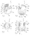
- the pressure element 6 is configured to be inserted into the receiving part 5 through the lower opening 56, whereby the second portion 63 is compressed during insertion.
- the pressure element may be inserted through the first end 5a and the passage 51.
- the outer diameter of the cylindrical first portion 61 of the pressure element 6 is smaller than the inner diameter of the passage 51 to such an extent that the clamping element 7 fits there-between. Because the second portion 63 of the pressure element 6 has an outer diameter that is smaller than an inner diameter of the accommodation space 55 and because the second portion 63 has a flexible wall, the second portion 63 can expand within the accommodation space 55 when the screw head 3 is inserted.
- the insertion force for inserting the head 3 into the receiving part 5 should not be too high.
- the achieved friction of the head 3 with respect to the pressure element 6 after insertion of the head might not be strong enough for convenient handling.
- the clamping element 7 is actuated in a next step using a tool 150 as shown in Figs. 15e and 15f .
- the tool 150 may be formed as a tubular rod with engagement portions at the front side that are arranged and sized so as to fit in the engagement portions 75 of the clamping element 7.
- the clamping element 7 is rotated by rotating the tool 150 so that the pins 9a, 9b are guided in the helical grooves 73a, 73b. Thereby, the clamping element 7 advances downward until its inner surface portion 72 contacts the outer first surface portion 65 of the pressure element 6.
- Fig. 15f depicts a partial cross-sectional view which illustrates how the associated groove 73b has moved relative to the mounted pin 9b.
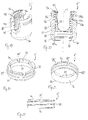
- the receiving part 5' comprises an internal thread 90 that extends from the end of the internal thread 54 in the direction of the accommodation space 55 to an axial height of approximately slightly below the bottom of the U-shaped recess 52.
- the internal thread 90 may be separated from the internal thread 54 by the undercut portion 54a.
- a thread pitch of the internal thread 90 is substantially the same as a thread pitch of the internal thread 54 and an outer diameter of the internal thread 90 is smaller than an inner diameter of the internal thread 54.
- the shape of the thread may be different from the shape of the internal thread 54.
- the thread flanks may have a triangular cross-section or any other cross-section.
- the dimensions of the threads should be such that the clamping element can be screwed through the upper portion of the passage 51 with the internal thread 54 into the portion with the thread 90. It should be noted, that in this embodiment, the receiving part 6' does not need to have pins.
- the clamping element 7' comprises an external thread 73' provided on its outer cylindrical surface that is configured to cooperate with the internal thread 90 of the receiving part 5'.
- the clamping element may have a plurality of engagement recesses 75'. In particular the number of engagement recesses 75' may be greater than in the first embodiment.
- the advancement structure in the form of the cooperating threads 73', 90 also provides a step less advancement of the clamping element 7' relative to the receiving part 5.'
- the threaded connection between the clamping element 7' and the receiving part 5' acts as a securing structure that inhibits inadvertent movement of the clamping element 7' relative to the receiving part 5'.
- the clamping element 7' is mounted by screwing it from the first end 5a of the receiving part 5' downward until it has an axial position that still allows to move the pressure element 6 upward to insert the head 3. Screwing-in the clamping element 7' renders the assembly simple and safe, as jamming of the clamping element in the passage 51 is prevented thereby.
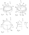
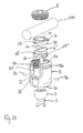
- the bone anchoring device differs from the first embodiment in the design of the coupling device and in particular in the design of the pressure element. Parts, portions and elements of the third embodiment that are identical or highly similar to those of the first embodiment, are marked with the same reference numerals and the description thereof will not be repeated.
- the coupling device comprises the receiving part 5 and the clamping element 7 of the first embodiment and a modified pressure element 6'.
- the flexible second portion 63' of the pressure element 6' comprises one single vertical slit 67' that is provided in a circumferential direction at an angle of substantially 90° relative to a longitudinal axis of the V-shaped rod support surface 62.
- An upper portion of the pressure element 6' that is between the horizontal recess 68' and the cylindrical portion 61 has a substantially spherical outer surface that is slightly recessed with respect to the ring 65a.
- the ring 65a has a slightly increased outer diameter forming a circumferential edge 65b.
- the use of the bone anchoring device is analogous to the use of the bone anchoring devices according to the previous embodiments.
- the horizontal slit 68' in connection with the vertical slit 67' renders the lower portion of the pressure element 6 more flexible. Therefore, an insertion force for the head 3 may be decreased.
- the frictional force to hold the inserted head 3 in the pressure element and the receiving part may be smaller. By means of the clamping element 7, the frictional force can be increased.
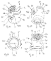
- the receiving part 5" includes on each leg 53a, 53b at one side from the central axis C opposite horizontal slits 501a, 501b that extend substantially perpendicular to the central axis C and are open towards the outer surface of the legs 53a, 53b.
- the recesses 501a, 501b may have a substantially square or rectangular cross-section with a size adapted to accommodate at least a portion of the clamping element 7" therein.
- the recesses 501a, 501b are located at an axial position that is approximately at the lower end of the internal thread 54 which allows to mount the clamping element from the side through the U-shaped recess 52.
- the grooves 62a, 62b extend substantially parallel to longitudinal axis of the rod-supporting surface 62.
- An inner surface of the legs 61a, 61 b is substantially flat.
- the legs 61a, 61 b comprise each a collar portion 600a, 600b.
- the collar portion is shaped so as to fit in a corresponding cutout in the receiving part 5" in the region of the horizontal recesses 501a, 501b as shown in particular in Fig. 33 .
- the legs 61a, 61b each comprise an elongate through-hole 601 a, 601 b the longitudinal axis of which is substantially parallel to the central axis C.
- the clamping element 7" is shaped as an open ring having free ends 70a, 70b and a slot 700 therebetween, so that the ring can act as a snap ring. More in detail, the clamping element 7" extends in circumferential direction slightly more than 180° around the central axis C. The slot 700 may be smaller or may be larger as shown. Further, the clamping element 7" has a substantially cylindrically shaped outer wall with an axial length that is such that the clamping element 7 fits approximately into the recessed region between the first portion 61' and the second portion 63' of the pressure element 6" as shown in Fig. 32 .
- the pressure element 6" is inserted into the receiving part 5" from the first end 5a.
- the legs 61a, 61b may be slightly flexed towards each other such that the pressure element can be maintained at a desired axial position.
- the clamping element 7" is inserted into the slits 501a, 501b of the receiving part 5" until it extends around the pressure element 6" just beneath the cylindrical first portion 61'.
- the protrusion 730 is aligned with the center of the substantially U-shaped recess and the rod-supporting surface 62 is also aligned with the U-shaped recess 52 of the receiving part 5".
- One of the slits 67 is located at a circumferential position corresponding to the center of the rod-supporting 62 of the pressure element 6".
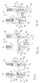
- the corresponding protrusion 721 at the inner surface 720 of the clamping element 7" can engage the widened portion 68 of the slit 67 as depicted in Fig. 46c . Thereafter, as shown in Fig. 46d , the pressure element 6" and the clamping element 7" are moved downward together as indicated by the arrow al.
- the elongate through-holes 601a, 601b overlap with the bores 59a', 59b', so that the pins 9a', 9b' can be inserted into the bores and extend into the through-holes 601a, 601b.
- the clamping element 7" is rotated in the clockwise direction around the central axis C (arrow c1).
- the rotation can be effected using a tool (not shown) that engages the protrusion 730.
- the rounded protrusions 721 move out of the recesses 68 of the pressure element and press against the flexible second surface portion 63' of the pressure element 6".
- the clamping force onto the head 3 is increased.
- the rotational movement is limited by the abutment of the protrusions 730 against the sidewall of the shallow recess 502.
- the pins 9a', 9b' prevent the pressure element 6" from escaping out of the receiving part 5".
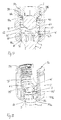
- the bone anchoring element is identical to the previous embodiments.
- the receiving part 5"', the clamping element 7'" and the pressure element 6'" are manufactured as a monolithic piece and separated after manufacturing.
- the pressure element has a shape like the pressure element in the first embodiment.
- the clamping element is similar to the clamping element of the first and second embodiment, however, instead of the two grooves 73a, 73b the clamping element 7"' comprises on its outer surface two helical projections 7000a, 7000b. These helical projections are configured to engage a corresponding helical grooves 9000a, 9000b in the receiving part 5"'.
- the clamping element 7"' is monolithically connected to the pressure element 6'" at predetermined breaking points P.
- the predetermined breaking points have a size such that by engagement of the clamping element 7"' with a tool that cooperates with the recesses 75 and rotating the clamping element, the predetermined breaking points P break so that the clamping element 7'" and the pressure element 6"' become separated.
- the clamping element 7'" is connected to the receiving part 5'" monolithically at predetermined breaking points Q as shown in Figs. 48 and 50 , wherein the size of the breaking points Q is such that by rotation of the clamping element with a tool the connection between the receiving part 5'" and the clamping element 7'" breaks at the predetermined breaking points Q.
- a method for manufacturing the coupling device may be an additive manufacturing method such as selective laser sintering, selective laser melting, electron beam-sintering and electron beam-melting.
- locking elements all kinds of locking devices can be used, such as bayonet-type locking devices, two-part locking devices that allow to clamp the rod and the head independently with two locking elements, outer locking nuts, etc..
Landscapes
- Health & Medical Sciences (AREA)
- Orthopedic Medicine & Surgery (AREA)
- Neurology (AREA)
- Life Sciences & Earth Sciences (AREA)
- Surgery (AREA)
- Heart & Thoracic Surgery (AREA)
- Engineering & Computer Science (AREA)
- Biomedical Technology (AREA)
- Nuclear Medicine, Radiotherapy & Molecular Imaging (AREA)
- Medical Informatics (AREA)
- Molecular Biology (AREA)
- Animal Behavior & Ethology (AREA)
- General Health & Medical Sciences (AREA)
- Public Health (AREA)
- Veterinary Medicine (AREA)
- Surgical Instruments (AREA)
Priority Applications (8)
| Application Number | Priority Date | Filing Date | Title |
|---|---|---|---|
| EP15167435.5A EP3092963B1 (de) | 2015-05-12 | 2015-05-12 | Kopplungsvorrichtung zum koppeln einer stange an ein knochenverankerungselement und knochenverankerungsvorrichtung mit solch einer kopplungsvorrichtung |
| JP2016093654A JP6785059B2 (ja) | 2015-05-12 | 2016-05-09 | ロッドを骨固定要素に連結するための連結装置、および骨固定装置 |
| CN201610302621.4A CN106137364B (zh) | 2015-05-12 | 2016-05-09 | 联接装置以及骨锚固装置 |
| US15/152,044 US9839446B2 (en) | 2015-05-12 | 2016-05-11 | Coupling device for coupling a rod to a bone anchoring element and bone anchoring device with such a coupling device |
| US15/818,278 US10271877B2 (en) | 2015-05-12 | 2017-11-20 | Coupling device for coupling a rod to a bone anchoring element and bone anchoring device with such a coupling device |
| US16/356,293 US10779863B2 (en) | 2015-05-12 | 2019-03-18 | Coupling device for coupling a rod to a bone anchoring element and bone anchoring device with such a coupling device |
| US16/996,425 US11638597B2 (en) | 2015-05-12 | 2020-08-18 | Coupling device for coupling a rod to a bone anchoring element and bone anchoring device with such a coupling device |
| US18/119,489 US20230277222A1 (en) | 2015-05-12 | 2023-03-09 | Coupling device for coupling a rod to a bone anchoring element and bone anchoring device with such a coupling device |
Applications Claiming Priority (1)
| Application Number | Priority Date | Filing Date | Title |
|---|---|---|---|
| EP15167435.5A EP3092963B1 (de) | 2015-05-12 | 2015-05-12 | Kopplungsvorrichtung zum koppeln einer stange an ein knochenverankerungselement und knochenverankerungsvorrichtung mit solch einer kopplungsvorrichtung |
Publications (2)
| Publication Number | Publication Date |
|---|---|
| EP3092963A1 true EP3092963A1 (de) | 2016-11-16 |
| EP3092963B1 EP3092963B1 (de) | 2017-07-12 |
Family
ID=53175339
Family Applications (1)
| Application Number | Title | Priority Date | Filing Date |
|---|---|---|---|
| EP15167435.5A Active EP3092963B1 (de) | 2015-05-12 | 2015-05-12 | Kopplungsvorrichtung zum koppeln einer stange an ein knochenverankerungselement und knochenverankerungsvorrichtung mit solch einer kopplungsvorrichtung |
Country Status (4)
| Country | Link |
|---|---|
| US (5) | US9839446B2 (de) |
| EP (1) | EP3092963B1 (de) |
| JP (1) | JP6785059B2 (de) |
| CN (1) | CN106137364B (de) |
Cited By (3)
| Publication number | Priority date | Publication date | Assignee | Title |
|---|---|---|---|---|
| CN110013298A (zh) * | 2018-01-10 | 2019-07-16 | 比德尔曼技术有限责任两合公司 | 多轴骨锚固装置以及器械和多轴骨锚固装置的系统 |
| IT202000020935A1 (it) * | 2020-09-04 | 2022-03-04 | Tsunami Medical S R L | Dispositivo peduncolare |
| WO2023215480A1 (en) * | 2022-05-04 | 2023-11-09 | Corelink, Llc | Bone screw for attaching rod to bone |
Families Citing this family (27)
| Publication number | Priority date | Publication date | Assignee | Title |
|---|---|---|---|---|
| US9980753B2 (en) * | 2009-06-15 | 2018-05-29 | Roger P Jackson | pivotal anchor with snap-in-place insert having rotation blocking extensions |
| AU2010260521C1 (en) * | 2008-08-01 | 2013-08-01 | Roger P. Jackson | Longitudinal connecting member with sleeved tensioned cords |
| US9993269B2 (en) * | 2011-07-15 | 2018-06-12 | Globus Medical, Inc. | Orthopedic fixation devices and methods of installation thereof |
| EP2893890B1 (de) * | 2014-01-13 | 2016-11-02 | Biedermann Technologies GmbH & Co. KG | Kupplungsvorrichtung zur Verbindung einer Stange an ein Knochenverankerungselement und polyaxiale Knochenverankerungsvorrichtung |
| EP3092962B1 (de) * | 2015-05-12 | 2017-10-04 | Biedermann Technologies GmbH & Co. KG | Instrument zur verwendung mit einer polyaxialen knochenverankerungsvorrichtung und system mit dem instrument und polyaxiale knochenverankerungsvorrichtung |
| EP3092963B1 (de) * | 2015-05-12 | 2017-07-12 | Biedermann Technologies GmbH & Co. KG | Kopplungsvorrichtung zum koppeln einer stange an ein knochenverankerungselement und knochenverankerungsvorrichtung mit solch einer kopplungsvorrichtung |
| EP3120791B1 (de) | 2015-07-24 | 2017-11-22 | Biedermann Technologies GmbH & Co. KG | Polyaxiale knochenverankerungsvorrichtung und instrument zur verwendung damit |
| US10368916B2 (en) * | 2017-01-11 | 2019-08-06 | Warsaw Orthopedic, Inc. | Spinal implant system and methods of use |
| US20180216745A1 (en) * | 2017-02-02 | 2018-08-02 | Fisher Controls International Llc | Modular valve trim assemblies for control valves |
| WO2018191131A1 (en) * | 2017-04-10 | 2018-10-18 | Life Spine, Inc. (A Delaware Corporation) | Modular bone screw |
| US20210128201A1 (en) * | 2017-04-10 | 2021-05-06 | Life Spine, Inc. | Bottom loading polyaxial screw |
| US10781846B2 (en) * | 2017-06-19 | 2020-09-22 | Divergent Technologies, Inc. | 3-D-printed components including fasteners and methods for producing same |
| EP3476340B1 (de) * | 2017-10-25 | 2021-06-02 | Biedermann Technologies GmbH & Co. KG | Polyaxiale knochenverankerungsvorrichtung |
| US10258385B1 (en) * | 2017-12-12 | 2019-04-16 | Spinal Llc | Bottom loading polyaxial ball and socket fastener with blocking ring with notched split ring |
| EP3708097B1 (de) | 2017-12-22 | 2023-06-14 | Biedermann Technologies GmbH & Co. KG | Vorrichtung zur polyaxialen knochenverankerung und system eines instruments und eine vorrichtung zur polyaxialen knochenverankerung |
| WO2019130197A1 (en) * | 2017-12-29 | 2019-07-04 | Pirelli Tyre S.P.A. | Tyre for vehicle wheels comprising an anchoring element of an object to an inner surface of the tyre and process for producing said tyre |
| EP3536271B1 (de) * | 2018-03-06 | 2022-05-04 | Biedermann Technologies GmbH & Co. KG | Vorrichtung zur polyaxialen knochenverankerung und system eines instruments und eine vorrichtung zur polyaxialen knochenverankerung |
| US11241259B2 (en) | 2018-08-30 | 2022-02-08 | Zimmer Biomet Spine, Inc. | Bone anchor |
| US11234738B2 (en) | 2018-11-16 | 2022-02-01 | Roger P. Jackson | Pivotal bone anchor assembly having a deployable collet insert with internal pressure ring |
| US11559333B2 (en) * | 2019-01-21 | 2023-01-24 | Zimmer Biomet Spine, Inc. | Bone anchor |
| US10864090B2 (en) * | 2019-04-23 | 2020-12-15 | Warsaw Orthopedic, Inc. | Spinal implant system and methods of use |
| EP3785649B1 (de) | 2019-08-30 | 2022-08-03 | Biedermann Technologies GmbH & Co. KG | Knochenverankerungsvorrichtung |
| WO2021127251A1 (en) | 2019-12-17 | 2021-06-24 | Jackson Roger P | Bone anchor assembly with closed ring retainer and internal snap ring |
| EP3878386B1 (de) * | 2020-03-12 | 2023-08-30 | Biedermann Technologies GmbH & Co. KG | Kopplungsvorrichtung zur verwendung mit einem knochenverankerungselement und knochenverankerungsvorrichtung mit solch einer kopplungsvorrichtung |
| EP4074271A1 (de) | 2021-04-15 | 2022-10-19 | Biedermann Technologies GmbH & Co. KG | Polyaxiale knochenverankerungsvorrichtung |
| US11828380B2 (en) | 2021-07-23 | 2023-11-28 | Fisher Controls International Llc | Valve bodies and methods of manufacturing the same |
| US20230301686A1 (en) * | 2022-03-25 | 2023-09-28 | Globus Medical, Inc. | Stabilizing bones using screws and rods |
Citations (8)
| Publication number | Priority date | Publication date | Assignee | Title |
|---|---|---|---|---|
| US5882350A (en) * | 1995-04-13 | 1999-03-16 | Fastenetix, Llc | Polyaxial pedicle screw having a threaded and tapered compression locking mechanism |
| US6248105B1 (en) | 1997-05-17 | 2001-06-19 | Synthes (U.S.A.) | Device for connecting a longitudinal support with a pedicle screw |
| US20070167949A1 (en) * | 2004-10-20 | 2007-07-19 | Moti Altarac | Screw systems and methods for use in stabilization of bone structures |
| US20120046701A1 (en) * | 2009-03-12 | 2012-02-23 | Euros | Spinal implant with a lockable ball joint |
| US20130096622A1 (en) | 2011-08-18 | 2013-04-18 | Timo Biedermann | Polyaxial bone anchoring device |
| US20140257411A1 (en) * | 2013-03-08 | 2014-09-11 | Warsaw Orthopedic, Inc. | Bone fastener and methods of use |
| US8926671B2 (en) | 2009-02-20 | 2015-01-06 | Biedermann Technologies Gmbh & Co. Kg | Receiving part for receiving a rod for coupling the rod to a bone anchoring element and a bone anchoring device with such a receiving part |
| EP2851021A1 (de) * | 2013-09-19 | 2015-03-25 | Biedermann Technologies GmbH & Co. KG | Kupplungsvorrichtung für die Verbindung einer Stange in einem Knochenverankerungselement, polyaxiale Knochenverankerungsvorrichtung und modulare Stabilisierungsvorrichtung |
Family Cites Families (12)
| Publication number | Priority date | Publication date | Assignee | Title |
|---|---|---|---|---|
| CN2803295Y (zh) * | 2004-07-30 | 2006-08-09 | 先锋实验室公司 | 脊柱固定系统 |
| US9980753B2 (en) * | 2009-06-15 | 2018-05-29 | Roger P Jackson | pivotal anchor with snap-in-place insert having rotation blocking extensions |
| US7901437B2 (en) * | 2007-01-26 | 2011-03-08 | Jackson Roger P | Dynamic stabilization member with molded connection |
| US20100160980A1 (en) * | 2007-07-26 | 2010-06-24 | Biotechni America Spine Group, Inc. | Spinal fixation assembly |
| ES2378588T3 (es) * | 2008-12-30 | 2012-04-16 | Biedermann Motech Gmbh | Parte de recepción para recibir una varilla para acoplar la varilla en un elemento de anclaje óseo y dispositivo de anclaje óseo con tal parte de recepción |
| EP2753252A1 (de) * | 2009-06-15 | 2014-07-16 | Jackson, Roger P. | Polyaxialer knochenanker mit pop-on-schaft und presssitzfixierung mit niedrigprofilkantensperre |
| CA2774471A1 (en) * | 2009-10-05 | 2011-04-14 | James L. Surber | Polyaxial bone anchor with non-pivotable retainer and pop-on shank, some with friction fit |
| US9358047B2 (en) * | 2011-07-15 | 2016-06-07 | Globus Medical, Inc. | Orthopedic fixation devices and methods of installation thereof |
| US8888827B2 (en) * | 2011-07-15 | 2014-11-18 | Globus Medical, Inc. | Orthopedic fixation devices and methods of installation thereof |
| EP2570090B1 (de) * | 2011-09-15 | 2015-04-01 | Biedermann Technologies GmbH & Co. KG | Mehrachsige Knochenverankerungsvorrichtung mit vergrößertem Schwenkwinkel |
| EP2764840B1 (de) * | 2013-02-11 | 2017-05-03 | Biedermann Technologies GmbH & Co. KG | Kopplungsanordnung zum Koppeln einer Stange an ein Knochenverankerungselement und Knochenverankerungsvorrichtung mit einer derartigen Kopplungsanordnung |
| EP3092963B1 (de) * | 2015-05-12 | 2017-07-12 | Biedermann Technologies GmbH & Co. KG | Kopplungsvorrichtung zum koppeln einer stange an ein knochenverankerungselement und knochenverankerungsvorrichtung mit solch einer kopplungsvorrichtung |
-
2015
- 2015-05-12 EP EP15167435.5A patent/EP3092963B1/de active Active
-
2016
- 2016-05-09 JP JP2016093654A patent/JP6785059B2/ja active Active
- 2016-05-09 CN CN201610302621.4A patent/CN106137364B/zh not_active Expired - Fee Related
- 2016-05-11 US US15/152,044 patent/US9839446B2/en active Active
-
2017
- 2017-11-20 US US15/818,278 patent/US10271877B2/en active Active
-
2019
- 2019-03-18 US US16/356,293 patent/US10779863B2/en active Active
-
2020
- 2020-08-18 US US16/996,425 patent/US11638597B2/en active Active
-
2023
- 2023-03-09 US US18/119,489 patent/US20230277222A1/en active Pending
Patent Citations (9)
| Publication number | Priority date | Publication date | Assignee | Title |
|---|---|---|---|---|
| US5882350A (en) * | 1995-04-13 | 1999-03-16 | Fastenetix, Llc | Polyaxial pedicle screw having a threaded and tapered compression locking mechanism |
| US6248105B1 (en) | 1997-05-17 | 2001-06-19 | Synthes (U.S.A.) | Device for connecting a longitudinal support with a pedicle screw |
| US20070167949A1 (en) * | 2004-10-20 | 2007-07-19 | Moti Altarac | Screw systems and methods for use in stabilization of bone structures |
| US8926671B2 (en) | 2009-02-20 | 2015-01-06 | Biedermann Technologies Gmbh & Co. Kg | Receiving part for receiving a rod for coupling the rod to a bone anchoring element and a bone anchoring device with such a receiving part |
| US20120046701A1 (en) * | 2009-03-12 | 2012-02-23 | Euros | Spinal implant with a lockable ball joint |
| US8951294B2 (en) | 2009-03-12 | 2015-02-10 | Euros | Spinal implant with a lockable ball joint |
| US20130096622A1 (en) | 2011-08-18 | 2013-04-18 | Timo Biedermann | Polyaxial bone anchoring device |
| US20140257411A1 (en) * | 2013-03-08 | 2014-09-11 | Warsaw Orthopedic, Inc. | Bone fastener and methods of use |
| EP2851021A1 (de) * | 2013-09-19 | 2015-03-25 | Biedermann Technologies GmbH & Co. KG | Kupplungsvorrichtung für die Verbindung einer Stange in einem Knochenverankerungselement, polyaxiale Knochenverankerungsvorrichtung und modulare Stabilisierungsvorrichtung |
Cited By (6)
| Publication number | Priority date | Publication date | Assignee | Title |
|---|---|---|---|---|
| CN110013298A (zh) * | 2018-01-10 | 2019-07-16 | 比德尔曼技术有限责任两合公司 | 多轴骨锚固装置以及器械和多轴骨锚固装置的系统 |
| EP3510954A1 (de) * | 2018-01-10 | 2019-07-17 | Biedermann Technologies GmbH & Co. KG | Vorrichtung zur polyaxialen knochenverankerung und system eines instruments und eine vorrichtung zur polyaxialen knochenverankerung |
| US11123108B2 (en) | 2018-01-10 | 2021-09-21 | Biedermann Technologies Gmbh & Co. Kg | Polyaxial bone anchoring device and system including an instrument and a polyaxial bone anchoring device |
| US11937853B2 (en) | 2018-01-10 | 2024-03-26 | Biedermann Technologies Gmbh & Co. Kg | Polyaxial bone anchoring device and system including an instrument and a polyaxial bone anchoring device |
| IT202000020935A1 (it) * | 2020-09-04 | 2022-03-04 | Tsunami Medical S R L | Dispositivo peduncolare |
| WO2023215480A1 (en) * | 2022-05-04 | 2023-11-09 | Corelink, Llc | Bone screw for attaching rod to bone |
Also Published As
| Publication number | Publication date |
|---|---|
| US20190274739A1 (en) | 2019-09-12 |
| US10779863B2 (en) | 2020-09-22 |
| US20160331412A1 (en) | 2016-11-17 |
| US11638597B2 (en) | 2023-05-02 |
| US20210030447A1 (en) | 2021-02-04 |
| JP6785059B2 (ja) | 2020-11-18 |
| JP2016209588A (ja) | 2016-12-15 |
| US20180132903A1 (en) | 2018-05-17 |
| US9839446B2 (en) | 2017-12-12 |
| US20230277222A1 (en) | 2023-09-07 |
| US10271877B2 (en) | 2019-04-30 |
| CN106137364A (zh) | 2016-11-23 |
| EP3092963B1 (de) | 2017-07-12 |
| CN106137364B (zh) | 2020-09-01 |
Similar Documents
| Publication | Publication Date | Title |
|---|---|---|
| EP3092963B1 (de) | Kopplungsvorrichtung zum koppeln einer stange an ein knochenverankerungselement und knochenverankerungsvorrichtung mit solch einer kopplungsvorrichtung | |
| US10022158B2 (en) | Coupling assembly for coupling a rod to a bone anchoring element, kit of such a coupling assembly different rod receiving elements and bone anchoring device | |
| EP2764840B1 (de) | Kopplungsanordnung zum Koppeln einer Stange an ein Knochenverankerungselement und Knochenverankerungsvorrichtung mit einer derartigen Kopplungsanordnung | |
| EP2455028B1 (de) | Polyaxiale Knochenverankerungsvorrichtung | |
| EP2679179B1 (de) | Knochenverankerungsvorrichtung | |
| JP5415722B2 (ja) | 骨固定装置 | |
| US11207106B2 (en) | Polyaxial bone anchoring device | |
| EP1741396B1 (de) | Knochenverankerungsvorrichtung | |
| US9155568B2 (en) | Bone anchoring device | |
| US20150196338A1 (en) | Coupling assembly for coupling a rod to a bone anchoring element, and polyaxial bone anchoring device | |
| EP2221013A1 (de) | Aufnahmeteil für die Aufnahme einer Stange zur Kopplung der Stange in einem Knochenverankerungselement und eine Knochenverankerungsvorrichtung mit einem derartigen Aufnahmeteil | |
| CN109700491B (zh) | 多轴线骨锚固装置 | |
| CN112438789A (zh) | 骨锚固装置 | |
| CN112971953A (zh) | 联接装置以及用于将联接装置布置在骨锚固件的头部上的器械 |
Legal Events
| Date | Code | Title | Description |
|---|---|---|---|
| PUAI | Public reference made under article 153(3) epc to a published international application that has entered the european phase |
Free format text: ORIGINAL CODE: 0009012 |
|
| 17P | Request for examination filed |
Effective date: 20160315 |
|
| AK | Designated contracting states |
Kind code of ref document: A1 Designated state(s): AL AT BE BG CH CY CZ DE DK EE ES FI FR GB GR HR HU IE IS IT LI LT LU LV MC MK MT NL NO PL PT RO RS SE SI SK SM TR |
|
| AX | Request for extension of the european patent |
Extension state: BA ME |
|
| GRAP | Despatch of communication of intention to grant a patent |
Free format text: ORIGINAL CODE: EPIDOSNIGR1 |
|
| INTG | Intention to grant announced |
Effective date: 20170119 |
|
| GRAS | Grant fee paid |
Free format text: ORIGINAL CODE: EPIDOSNIGR3 |
|
| GRAA | (expected) grant |
Free format text: ORIGINAL CODE: 0009210 |
|
| AK | Designated contracting states |
Kind code of ref document: B1 Designated state(s): AL AT BE BG CH CY CZ DE DK EE ES FI FR GB GR HR HU IE IS IT LI LT LU LV MC MK MT NL NO PL PT RO RS SE SI SK SM TR |
|
| REG | Reference to a national code |
Ref country code: GB Ref legal event code: FG4D |
|
| REG | Reference to a national code |
Ref country code: CH Ref legal event code: EP Ref country code: CH Ref legal event code: NV Representative=s name: NOVAGRAAF INTERNATIONAL SA, CH |
|
| REG | Reference to a national code |
Ref country code: AT Ref legal event code: REF Ref document number: 907596 Country of ref document: AT Kind code of ref document: T Effective date: 20170715 |
|
| REG | Reference to a national code |
Ref country code: IE Ref legal event code: FG4D |
|
| REG | Reference to a national code |
Ref country code: DE Ref legal event code: R096 Ref document number: 602015003488 Country of ref document: DE |
|
| REG | Reference to a national code |
Ref country code: NL Ref legal event code: MP Effective date: 20170712 |
|
| REG | Reference to a national code |
Ref country code: LT Ref legal event code: MG4D |
|
| REG | Reference to a national code |
Ref country code: AT Ref legal event code: MK05 Ref document number: 907596 Country of ref document: AT Kind code of ref document: T Effective date: 20170712 |
|
| PG25 | Lapsed in a contracting state [announced via postgrant information from national office to epo] |
Ref country code: SE Free format text: LAPSE BECAUSE OF FAILURE TO SUBMIT A TRANSLATION OF THE DESCRIPTION OR TO PAY THE FEE WITHIN THE PRESCRIBED TIME-LIMIT Effective date: 20170712 Ref country code: NO Free format text: LAPSE BECAUSE OF FAILURE TO SUBMIT A TRANSLATION OF THE DESCRIPTION OR TO PAY THE FEE WITHIN THE PRESCRIBED TIME-LIMIT Effective date: 20171012 Ref country code: HR Free format text: LAPSE BECAUSE OF FAILURE TO SUBMIT A TRANSLATION OF THE DESCRIPTION OR TO PAY THE FEE WITHIN THE PRESCRIBED TIME-LIMIT Effective date: 20170712 Ref country code: NL Free format text: LAPSE BECAUSE OF FAILURE TO SUBMIT A TRANSLATION OF THE DESCRIPTION OR TO PAY THE FEE WITHIN THE PRESCRIBED TIME-LIMIT Effective date: 20170712 Ref country code: LT Free format text: LAPSE BECAUSE OF FAILURE TO SUBMIT A TRANSLATION OF THE DESCRIPTION OR TO PAY THE FEE WITHIN THE PRESCRIBED TIME-LIMIT Effective date: 20170712 Ref country code: FI Free format text: LAPSE BECAUSE OF FAILURE TO SUBMIT A TRANSLATION OF THE DESCRIPTION OR TO PAY THE FEE WITHIN THE PRESCRIBED TIME-LIMIT Effective date: 20170712 Ref country code: AT Free format text: LAPSE BECAUSE OF FAILURE TO SUBMIT A TRANSLATION OF THE DESCRIPTION OR TO PAY THE FEE WITHIN THE PRESCRIBED TIME-LIMIT Effective date: 20170712 |
|
| PG25 | Lapsed in a contracting state [announced via postgrant information from national office to epo] |
Ref country code: PL Free format text: LAPSE BECAUSE OF FAILURE TO SUBMIT A TRANSLATION OF THE DESCRIPTION OR TO PAY THE FEE WITHIN THE PRESCRIBED TIME-LIMIT Effective date: 20170712 Ref country code: LV Free format text: LAPSE BECAUSE OF FAILURE TO SUBMIT A TRANSLATION OF THE DESCRIPTION OR TO PAY THE FEE WITHIN THE PRESCRIBED TIME-LIMIT Effective date: 20170712 Ref country code: ES Free format text: LAPSE BECAUSE OF FAILURE TO SUBMIT A TRANSLATION OF THE DESCRIPTION OR TO PAY THE FEE WITHIN THE PRESCRIBED TIME-LIMIT Effective date: 20170712 Ref country code: IS Free format text: LAPSE BECAUSE OF FAILURE TO SUBMIT A TRANSLATION OF THE DESCRIPTION OR TO PAY THE FEE WITHIN THE PRESCRIBED TIME-LIMIT Effective date: 20171112 Ref country code: BG Free format text: LAPSE BECAUSE OF FAILURE TO SUBMIT A TRANSLATION OF THE DESCRIPTION OR TO PAY THE FEE WITHIN THE PRESCRIBED TIME-LIMIT Effective date: 20171012 Ref country code: RS Free format text: LAPSE BECAUSE OF FAILURE TO SUBMIT A TRANSLATION OF THE DESCRIPTION OR TO PAY THE FEE WITHIN THE PRESCRIBED TIME-LIMIT Effective date: 20170712 Ref country code: GR Free format text: LAPSE BECAUSE OF FAILURE TO SUBMIT A TRANSLATION OF THE DESCRIPTION OR TO PAY THE FEE WITHIN THE PRESCRIBED TIME-LIMIT Effective date: 20171013 |
|
| REG | Reference to a national code |
Ref country code: DE Ref legal event code: R097 Ref document number: 602015003488 Country of ref document: DE |
|
| PG25 | Lapsed in a contracting state [announced via postgrant information from national office to epo] |
Ref country code: CZ Free format text: LAPSE BECAUSE OF FAILURE TO SUBMIT A TRANSLATION OF THE DESCRIPTION OR TO PAY THE FEE WITHIN THE PRESCRIBED TIME-LIMIT Effective date: 20170712 Ref country code: DK Free format text: LAPSE BECAUSE OF FAILURE TO SUBMIT A TRANSLATION OF THE DESCRIPTION OR TO PAY THE FEE WITHIN THE PRESCRIBED TIME-LIMIT Effective date: 20170712 |
|
| PLBE | No opposition filed within time limit |
Free format text: ORIGINAL CODE: 0009261 |
|
| STAA | Information on the status of an ep patent application or granted ep patent |
Free format text: STATUS: NO OPPOSITION FILED WITHIN TIME LIMIT |
|
| PG25 | Lapsed in a contracting state [announced via postgrant information from national office to epo] |
Ref country code: SM Free format text: LAPSE BECAUSE OF FAILURE TO SUBMIT A TRANSLATION OF THE DESCRIPTION OR TO PAY THE FEE WITHIN THE PRESCRIBED TIME-LIMIT Effective date: 20170712 Ref country code: SK Free format text: LAPSE BECAUSE OF FAILURE TO SUBMIT A TRANSLATION OF THE DESCRIPTION OR TO PAY THE FEE WITHIN THE PRESCRIBED TIME-LIMIT Effective date: 20170712 Ref country code: EE Free format text: LAPSE BECAUSE OF FAILURE TO SUBMIT A TRANSLATION OF THE DESCRIPTION OR TO PAY THE FEE WITHIN THE PRESCRIBED TIME-LIMIT Effective date: 20170712 Ref country code: IT Free format text: LAPSE BECAUSE OF FAILURE TO SUBMIT A TRANSLATION OF THE DESCRIPTION OR TO PAY THE FEE WITHIN THE PRESCRIBED TIME-LIMIT Effective date: 20170712 |
|
| 26N | No opposition filed |
Effective date: 20180413 |
|
| PG25 | Lapsed in a contracting state [announced via postgrant information from national office to epo] |
Ref country code: SI Free format text: LAPSE BECAUSE OF FAILURE TO SUBMIT A TRANSLATION OF THE DESCRIPTION OR TO PAY THE FEE WITHIN THE PRESCRIBED TIME-LIMIT Effective date: 20170712 |
|
| REG | Reference to a national code |
Ref country code: BE Ref legal event code: MM Effective date: 20180531 |
|
| PG25 | Lapsed in a contracting state [announced via postgrant information from national office to epo] |
Ref country code: MC Free format text: LAPSE BECAUSE OF FAILURE TO SUBMIT A TRANSLATION OF THE DESCRIPTION OR TO PAY THE FEE WITHIN THE PRESCRIBED TIME-LIMIT Effective date: 20170712 |
|
| REG | Reference to a national code |
Ref country code: IE Ref legal event code: MM4A |
|
| PG25 | Lapsed in a contracting state [announced via postgrant information from national office to epo] |
Ref country code: LU Free format text: LAPSE BECAUSE OF NON-PAYMENT OF DUE FEES Effective date: 20180512 |
|
| PG25 | Lapsed in a contracting state [announced via postgrant information from national office to epo] |
Ref country code: IE Free format text: LAPSE BECAUSE OF NON-PAYMENT OF DUE FEES Effective date: 20180512 Ref country code: FR Free format text: LAPSE BECAUSE OF NON-PAYMENT OF DUE FEES Effective date: 20180531 |
|
| PG25 | Lapsed in a contracting state [announced via postgrant information from national office to epo] |
Ref country code: BE Free format text: LAPSE BECAUSE OF NON-PAYMENT OF DUE FEES Effective date: 20180531 |
|
| PG25 | Lapsed in a contracting state [announced via postgrant information from national office to epo] |
Ref country code: MT Free format text: LAPSE BECAUSE OF NON-PAYMENT OF DUE FEES Effective date: 20180512 |
|
| PG25 | Lapsed in a contracting state [announced via postgrant information from national office to epo] |
Ref country code: TR Free format text: LAPSE BECAUSE OF FAILURE TO SUBMIT A TRANSLATION OF THE DESCRIPTION OR TO PAY THE FEE WITHIN THE PRESCRIBED TIME-LIMIT Effective date: 20170712 |
|
| PG25 | Lapsed in a contracting state [announced via postgrant information from national office to epo] |
Ref country code: PT Free format text: LAPSE BECAUSE OF FAILURE TO SUBMIT A TRANSLATION OF THE DESCRIPTION OR TO PAY THE FEE WITHIN THE PRESCRIBED TIME-LIMIT Effective date: 20170712 |
|
| PG25 | Lapsed in a contracting state [announced via postgrant information from national office to epo] |
Ref country code: MK Free format text: LAPSE BECAUSE OF NON-PAYMENT OF DUE FEES Effective date: 20170712 Ref country code: HU Free format text: LAPSE BECAUSE OF FAILURE TO SUBMIT A TRANSLATION OF THE DESCRIPTION OR TO PAY THE FEE WITHIN THE PRESCRIBED TIME-LIMIT; INVALID AB INITIO Effective date: 20150512 Ref country code: RO Free format text: LAPSE BECAUSE OF FAILURE TO SUBMIT A TRANSLATION OF THE DESCRIPTION OR TO PAY THE FEE WITHIN THE PRESCRIBED TIME-LIMIT Effective date: 20170712 Ref country code: CY Free format text: LAPSE BECAUSE OF FAILURE TO SUBMIT A TRANSLATION OF THE DESCRIPTION OR TO PAY THE FEE WITHIN THE PRESCRIBED TIME-LIMIT Effective date: 20170712 |
|
| PG25 | Lapsed in a contracting state [announced via postgrant information from national office to epo] |
Ref country code: AL Free format text: LAPSE BECAUSE OF FAILURE TO SUBMIT A TRANSLATION OF THE DESCRIPTION OR TO PAY THE FEE WITHIN THE PRESCRIBED TIME-LIMIT Effective date: 20170712 |
|
| P01 | Opt-out of the competence of the unified patent court (upc) registered |
Effective date: 20230525 |
|
| PGFP | Annual fee paid to national office [announced via postgrant information from national office to epo] |
Ref country code: DE Payment date: 20230531 Year of fee payment: 9 Ref country code: CH Payment date: 20230602 Year of fee payment: 9 |
|
| PGFP | Annual fee paid to national office [announced via postgrant information from national office to epo] |
Ref country code: GB Payment date: 20230515 Year of fee payment: 9 |