EP3092147B1 - Electric charging device, electric connection device, system and method for charging a vehicle battery - Google Patents
Electric charging device, electric connection device, system and method for charging a vehicle battery Download PDFInfo
- Publication number
- EP3092147B1 EP3092147B1 EP14799439.6A EP14799439A EP3092147B1 EP 3092147 B1 EP3092147 B1 EP 3092147B1 EP 14799439 A EP14799439 A EP 14799439A EP 3092147 B1 EP3092147 B1 EP 3092147B1
- Authority
- EP
- European Patent Office
- Prior art keywords
- charging
- arm
- head
- vehicle
- lifting device
- Prior art date
- Legal status (The legal status is an assumption and is not a legal conclusion. Google has not performed a legal analysis and makes no representation as to the accuracy of the status listed.)
- Active
Links
- 238000000034 method Methods 0.000 title description 10
- 238000011161 development Methods 0.000 description 10
- 230000018109 developmental process Effects 0.000 description 10
- 238000013461 design Methods 0.000 description 3
- 241000446313 Lamella Species 0.000 description 2
- 238000013459 approach Methods 0.000 description 2
- 230000008901 benefit Effects 0.000 description 2
- 238000010586 diagram Methods 0.000 description 2
- 240000001973 Ficus microcarpa Species 0.000 description 1
- 241000826860 Trapezium Species 0.000 description 1
- 238000007792 addition Methods 0.000 description 1
- 238000005452 bending Methods 0.000 description 1
- 230000008859 change Effects 0.000 description 1
- 235000019504 cigarettes Nutrition 0.000 description 1
- 230000001419 dependent effect Effects 0.000 description 1
- 238000001514 detection method Methods 0.000 description 1
- 238000006073 displacement reaction Methods 0.000 description 1
- 230000000694 effects Effects 0.000 description 1
- 230000005484 gravity Effects 0.000 description 1
- 230000003993 interaction Effects 0.000 description 1
- 238000005259 measurement Methods 0.000 description 1
- 230000008569 process Effects 0.000 description 1
- 238000012545 processing Methods 0.000 description 1
- 230000001681 protective effect Effects 0.000 description 1
- 239000007787 solid Substances 0.000 description 1
Images


Classifications
-
- B—PERFORMING OPERATIONS; TRANSPORTING
- B60—VEHICLES IN GENERAL
- B60L—PROPULSION OF ELECTRICALLY-PROPELLED VEHICLES; SUPPLYING ELECTRIC POWER FOR AUXILIARY EQUIPMENT OF ELECTRICALLY-PROPELLED VEHICLES; ELECTRODYNAMIC BRAKE SYSTEMS FOR VEHICLES IN GENERAL; MAGNETIC SUSPENSION OR LEVITATION FOR VEHICLES; MONITORING OPERATING VARIABLES OF ELECTRICALLY-PROPELLED VEHICLES; ELECTRIC SAFETY DEVICES FOR ELECTRICALLY-PROPELLED VEHICLES
- B60L53/00—Methods of charging batteries, specially adapted for electric vehicles; Charging stations or on-board charging equipment therefor; Exchange of energy storage elements in electric vehicles
- B60L53/30—Constructional details of charging stations
-
- B—PERFORMING OPERATIONS; TRANSPORTING
- B60—VEHICLES IN GENERAL
- B60L—PROPULSION OF ELECTRICALLY-PROPELLED VEHICLES; SUPPLYING ELECTRIC POWER FOR AUXILIARY EQUIPMENT OF ELECTRICALLY-PROPELLED VEHICLES; ELECTRODYNAMIC BRAKE SYSTEMS FOR VEHICLES IN GENERAL; MAGNETIC SUSPENSION OR LEVITATION FOR VEHICLES; MONITORING OPERATING VARIABLES OF ELECTRICALLY-PROPELLED VEHICLES; ELECTRIC SAFETY DEVICES FOR ELECTRICALLY-PROPELLED VEHICLES
- B60L53/00—Methods of charging batteries, specially adapted for electric vehicles; Charging stations or on-board charging equipment therefor; Exchange of energy storage elements in electric vehicles
- B60L53/10—Methods of charging batteries, specially adapted for electric vehicles; Charging stations or on-board charging equipment therefor; Exchange of energy storage elements in electric vehicles characterised by the energy transfer between the charging station and the vehicle
- B60L53/14—Conductive energy transfer
- B60L53/16—Connectors, e.g. plugs or sockets, specially adapted for charging electric vehicles
-
- B—PERFORMING OPERATIONS; TRANSPORTING
- B60—VEHICLES IN GENERAL
- B60L—PROPULSION OF ELECTRICALLY-PROPELLED VEHICLES; SUPPLYING ELECTRIC POWER FOR AUXILIARY EQUIPMENT OF ELECTRICALLY-PROPELLED VEHICLES; ELECTRODYNAMIC BRAKE SYSTEMS FOR VEHICLES IN GENERAL; MAGNETIC SUSPENSION OR LEVITATION FOR VEHICLES; MONITORING OPERATING VARIABLES OF ELECTRICALLY-PROPELLED VEHICLES; ELECTRIC SAFETY DEVICES FOR ELECTRICALLY-PROPELLED VEHICLES
- B60L53/00—Methods of charging batteries, specially adapted for electric vehicles; Charging stations or on-board charging equipment therefor; Exchange of energy storage elements in electric vehicles
- B60L53/10—Methods of charging batteries, specially adapted for electric vehicles; Charging stations or on-board charging equipment therefor; Exchange of energy storage elements in electric vehicles characterised by the energy transfer between the charging station and the vehicle
- B60L53/14—Conductive energy transfer
- B60L53/18—Cables specially adapted for charging electric vehicles
-
- B—PERFORMING OPERATIONS; TRANSPORTING
- B60—VEHICLES IN GENERAL
- B60L—PROPULSION OF ELECTRICALLY-PROPELLED VEHICLES; SUPPLYING ELECTRIC POWER FOR AUXILIARY EQUIPMENT OF ELECTRICALLY-PROPELLED VEHICLES; ELECTRODYNAMIC BRAKE SYSTEMS FOR VEHICLES IN GENERAL; MAGNETIC SUSPENSION OR LEVITATION FOR VEHICLES; MONITORING OPERATING VARIABLES OF ELECTRICALLY-PROPELLED VEHICLES; ELECTRIC SAFETY DEVICES FOR ELECTRICALLY-PROPELLED VEHICLES
- B60L53/00—Methods of charging batteries, specially adapted for electric vehicles; Charging stations or on-board charging equipment therefor; Exchange of energy storage elements in electric vehicles
- B60L53/30—Constructional details of charging stations
- B60L53/35—Means for automatic or assisted adjustment of the relative position of charging devices and vehicles
- B60L53/36—Means for automatic or assisted adjustment of the relative position of charging devices and vehicles by positioning the vehicle
-
- H—ELECTRICITY
- H01—ELECTRIC ELEMENTS
- H01R—ELECTRICALLY-CONDUCTIVE CONNECTIONS; STRUCTURAL ASSOCIATIONS OF A PLURALITY OF MUTUALLY-INSULATED ELECTRICAL CONNECTING ELEMENTS; COUPLING DEVICES; CURRENT COLLECTORS
- H01R13/00—Details of coupling devices of the kinds covered by groups H01R12/70 or H01R24/00 - H01R33/00
- H01R13/62—Means for facilitating engagement or disengagement of coupling parts or for holding them in engagement
- H01R13/629—Additional means for facilitating engagement or disengagement of coupling parts, e.g. aligning or guiding means, levers, gas pressure electrical locking indicators, manufacturing tolerances
- H01R13/631—Additional means for facilitating engagement or disengagement of coupling parts, e.g. aligning or guiding means, levers, gas pressure electrical locking indicators, manufacturing tolerances for engagement only
- H01R13/6315—Additional means for facilitating engagement or disengagement of coupling parts, e.g. aligning or guiding means, levers, gas pressure electrical locking indicators, manufacturing tolerances for engagement only allowing relative movement between coupling parts, e.g. floating connection
-
- H—ELECTRICITY
- H01—ELECTRIC ELEMENTS
- H01R—ELECTRICALLY-CONDUCTIVE CONNECTIONS; STRUCTURAL ASSOCIATIONS OF A PLURALITY OF MUTUALLY-INSULATED ELECTRICAL CONNECTING ELEMENTS; COUPLING DEVICES; CURRENT COLLECTORS
- H01R2201/00—Connectors or connections adapted for particular applications
- H01R2201/26—Connectors or connections adapted for particular applications for vehicles
-
- Y—GENERAL TAGGING OF NEW TECHNOLOGICAL DEVELOPMENTS; GENERAL TAGGING OF CROSS-SECTIONAL TECHNOLOGIES SPANNING OVER SEVERAL SECTIONS OF THE IPC; TECHNICAL SUBJECTS COVERED BY FORMER USPC CROSS-REFERENCE ART COLLECTIONS [XRACs] AND DIGESTS
- Y02—TECHNOLOGIES OR APPLICATIONS FOR MITIGATION OR ADAPTATION AGAINST CLIMATE CHANGE
- Y02T—CLIMATE CHANGE MITIGATION TECHNOLOGIES RELATED TO TRANSPORTATION
- Y02T10/00—Road transport of goods or passengers
- Y02T10/60—Other road transportation technologies with climate change mitigation effect
- Y02T10/70—Energy storage systems for electromobility, e.g. batteries
-
- Y—GENERAL TAGGING OF NEW TECHNOLOGICAL DEVELOPMENTS; GENERAL TAGGING OF CROSS-SECTIONAL TECHNOLOGIES SPANNING OVER SEVERAL SECTIONS OF THE IPC; TECHNICAL SUBJECTS COVERED BY FORMER USPC CROSS-REFERENCE ART COLLECTIONS [XRACs] AND DIGESTS
- Y02—TECHNOLOGIES OR APPLICATIONS FOR MITIGATION OR ADAPTATION AGAINST CLIMATE CHANGE
- Y02T—CLIMATE CHANGE MITIGATION TECHNOLOGIES RELATED TO TRANSPORTATION
- Y02T10/00—Road transport of goods or passengers
- Y02T10/60—Other road transportation technologies with climate change mitigation effect
- Y02T10/7072—Electromobility specific charging systems or methods for batteries, ultracapacitors, supercapacitors or double-layer capacitors
-
- Y—GENERAL TAGGING OF NEW TECHNOLOGICAL DEVELOPMENTS; GENERAL TAGGING OF CROSS-SECTIONAL TECHNOLOGIES SPANNING OVER SEVERAL SECTIONS OF THE IPC; TECHNICAL SUBJECTS COVERED BY FORMER USPC CROSS-REFERENCE ART COLLECTIONS [XRACs] AND DIGESTS
- Y02—TECHNOLOGIES OR APPLICATIONS FOR MITIGATION OR ADAPTATION AGAINST CLIMATE CHANGE
- Y02T—CLIMATE CHANGE MITIGATION TECHNOLOGIES RELATED TO TRANSPORTATION
- Y02T90/00—Enabling technologies or technologies with a potential or indirect contribution to GHG emissions mitigation
- Y02T90/10—Technologies relating to charging of electric vehicles
- Y02T90/12—Electric charging stations
-
- Y—GENERAL TAGGING OF NEW TECHNOLOGICAL DEVELOPMENTS; GENERAL TAGGING OF CROSS-SECTIONAL TECHNOLOGIES SPANNING OVER SEVERAL SECTIONS OF THE IPC; TECHNICAL SUBJECTS COVERED BY FORMER USPC CROSS-REFERENCE ART COLLECTIONS [XRACs] AND DIGESTS
- Y02—TECHNOLOGIES OR APPLICATIONS FOR MITIGATION OR ADAPTATION AGAINST CLIMATE CHANGE
- Y02T—CLIMATE CHANGE MITIGATION TECHNOLOGIES RELATED TO TRANSPORTATION
- Y02T90/00—Enabling technologies or technologies with a potential or indirect contribution to GHG emissions mitigation
- Y02T90/10—Technologies relating to charging of electric vehicles
- Y02T90/14—Plug-in electric vehicles
Definitions
- the present invention relates to an electrical charging device for charging a battery of a vehicle, an electrical connection device of a vehicle for charging a battery of the vehicle, a system for charging a battery of a vehicle and a method for charging a battery of a vehicle.
- Hybrid and electric vehicles use batteries, at least in part, to power their powertrain. If the battery of a vehicle is empty, it can be recharged at a charging station using a charging device.
- Automated conductive charging systems require a charging head, for example a plug, of the charging device to be guided precisely to a receiving head, for example a socket, of a connection device on a vehicle.
- Vehicles often have different locations for the receiving head due to their different designs. Uniformity is also not guaranteed by arranging a receiving head on the underbody of the vehicle, since vehicles are of different heights and the underbody of vehicles is therefore at different heights from a base area on which the vehicle is standing. Vehicles are usually only positioned precisely and sometimes at an angle by their vehicle drivers with an error of around +-10cm.
- the task of guiding the charging head to the receiving head can be managed, for example, by technically complex robots, for example with target detection, measurement and image processing systems.
- U.S. 2011 066 515 A1 describes an automatic plug-in station for charging electric and hybrid vehicles.
- the vehicle is positioned over a trap door.
- a positioning system recognizes the position of a socket on the vehicle.
- a plug extends and retracts vertically for plugging and unplugging into and out of the socket and is connected to a power source. Based on the detected position of the connector socket on the vehicle, the connector can be displaced horizontally in two dimensions, so that the connector enters the connector socket when extended vertically.
- the D1 ( U.S. 2013/076902 A1 ) relates to a charging station with an apparatus for charging the batteries of electric vehicles, which consists of a base plate, a lifting device connected thereto and a robotic arm.
- the robotic arm projects from the lifting device and has a device at the end remote from the lifting device which can be coupled to a plug connector on the electric vehicle.
- the robotic arm is designed in such a way that the device at the end of the robotic arm can be moved in three dimensions.
- the state of the art according to D2 ( U.S. 2011/181241 A1 ) relates to a charging system particularly suitable for charging the batteries of electrified motor vehicles with a charging head having a plurality of contacts which mate with a series of socket contacts on board the vehicle.
- the charging head is held from above and can be lowered onto the socket contacts on board the vehicle via a power operated system.
- the state of the art according to D3 ( U.S. 5,306,999A ) relates to an electric vehicle charging station for charging an electric vehicle.
- the electric vehicle charging station includes a base unit having an electrical control box coupled to an electrical cord and a retractable support arm having an electrical cord and an electrical connector. This arm can move between a retracted position and an extended position.
- the support arm assembly can be fitted with various support arms and/or linkages that allow it to move vertically and horizontally.
- the prior art D4 ( U.S. 5,495,159 ) relates to a charging system for driverless vehicles, the charging system having a rotatable electrode unit, the electrode unit being able to be contacted via a shaft with the charging socket of the vehicle by rotating the electrode unit around the shaft and extending it accordingly in order to make contact with the charging socket .
- the present invention discloses a loading device having the features of patent claim 1.
- an electric charging device for charging a battery of a vehicle, comprising: a lifting device to which a charging head is coupled; where the Charging head has a first plurality of first electrical contacts on or on a first surface of the charging head, which are at least partially connectable to an energy source for charging the battery; an actuator, by means of which the lifting device can be actuated in such a way that the charging head can be moved at least partially in a first direction, which is essentially perpendicular to the first surface; further wherein the lifting device is configured such that the loading head is movable in a second direction along the abutment surface upon impact in the first direction on an abutment surface by continued actuation of the lifting device by the actuator.
- a vehicle electrical connector for charging a battery of the vehicle, comprising: a receiving head having a second plurality of second electrical contacts on or on a second surface of the connector; guide means for receiving a loading head applied to the attachment device and moving substantially parallel to the second surface and for guiding the moving loading head and the receiving head into a predetermined positional relationship to each other; wherein if the charging head and the receiving head are substantially in the predetermined positional relationship to each other, the battery of the vehicle is chargeable via the second electrical contacts.
- a charging system for charging a battery of a vehicle is provided with: an electric charging device according to the invention installed outside the vehicle; and an electrical connection device according to the invention formed on the vehicle; wherein the charging head of the charging device is designed in such a way that it can be inserted into the guide device of the connection device and the first electrical contacts can be placed at least partially on the second electrical contacts for charging the battery.
- a method for charging a battery of a vehicle comprising: Actuating a lifting device by means of an actuator such that a charging head connected to the lifting device moves at least partially in a first direction which is substantially perpendicular to a first surface of the charging head, a first plurality of first electrical contacts being formed on the first surface , which are at least partially connected to a power source; and further such that if the loading head encounters an abutment surface in the first direction, the loading head moves in a second direction along the abutment surface; guiding the loading head moving along the abutment surface by means of guide means into a predetermined loading position with respect to a receiving head having second electrical contacts; and charging the battery of the vehicle from the power source via the first and second electrical contacts.
- a system for charging a battery of a vehicle can be provided with little technical effort, which can be actuated with an actuator, in particular with exactly one single actuator, such that when the vehicle is in a position within a predetermined area around a charging device, a charging head of the charging device is automatically guided to a receiving head on the vehicle.
- the vehicle can be guided into the predetermined area by means of a navigation or parking assistance system, for example.
- the actuator of the loading device has the effect that the loading head attached to the lifting device is first lifted onto the underbody of the vehicle and then automatically, pressed against the underbody, is moved along it.
- the height of The underbody of the vehicle does not have to be known, nor does it have to assume a specific value. Rather, the charging device can be used flexibly in a large number of vehicles without any adjustment. It may suffice if the height of the underbody assumes values in a specific value range.
- a single actuator causes a linear movement of a part of the lifting device, in particular a slider, which in turn causes the remaining movement of the loading device as described above.
- the charging device is technically particularly simple, robust and reliable.
- Charging on the underside of the vehicle has the advantage that disruptive interaction with the charging system or with the charging device is made more difficult. Furthermore, the design freedom of the vehicle manufacturer is not restricted by this solution.
- a connection device is designed on the vehicle in such a way that the moving charging head impinging on it is guided to the predetermined charging position of the charging head with respect to the receiving head even if there is a certain lateral offset.
- this is done purely mechanically without electronic elements.
- On the charging device side only the single actuator is preferably used.
- the first electrical contacts are designed as lamellae which are parallel to one another and are perpendicular to the first surface. As a result, the first contacts can be contacted in a particularly stable manner with corresponding contacts of a connecting device.
- At least one of the lamellae has a different length compared to the remaining lamellae. Contact can be made by pushing the lamellae into guide slots with contacts along the lamellae. Due to the different length of the at least one lamella, this first contact can be contacted earlier, later, longer or shorter than the contacting of the remaining first contacts.
- At least one of the lamellae is offset from the remaining lamellae in a direction along the lamellae. Due to the different length of the at least one lamella, this first contact can be contacted earlier or later than the remaining first contacts.
- the loading head is coupled to the lifting device via a first arm; wherein the first arm is coupled at a first end to the loading head via a first spring; and coupled at a second end to the remainder of the lifting means via a second spring.
- the actuator and the lifting device are designed in such a way that the lifting device can be actuated to move the loading head in that a linear movement of a slide of the lifting device is caused by the actuator.
- Linear movements are particularly simple and easy to control. The technical elements required for this are simple, not technically complex, robust and reliable.
- connection device According to a preferred development of the connection device according to the invention, the second electrical contacts are arranged parallel to one another, spaced apart in a direction parallel to the second surface. As a result, charging heads with first contacts arranged parallel to one another can be used for contacting the connection device.
- the receiving head is designed to be movable with respect to the vehicle and is connected to the vehicle via at least one spring.
- the at least one spring can exert a restoring force when the receiving head is deflected from a rest position.
- the connecting device can be automatically displaced in such a way that the charging head and the receiving head can be brought into the predetermined positional relationship with one another, that is to say that the first and second contacts can contact one another.
- Figure 1A 12 shows a schematic side view of an electric charging device 10 for charging a battery of a vehicle according to a first embodiment of a first aspect of the present invention in a first state.
- a charging head 12 has a first plurality of electrical contacts 14 on a first surface 13 of the charging head 12 .
- the electrical contacts 14 are in the form of lamellae which are parallel to one another and are perpendicular to the first surface 13 . Seen from the side, the slats are trapezoidal strips, the longer of the two parallel sides of the trapezium being connected to the first surface 13 in each case.
- the charging device 10 is set up on a base G, for example the ground, a floor, a vehicle floor or any other suitable flat surface. is advantageous mounting the charging device 10 on a surface that is lower than the ground and parallel to it, or in a recess, for example in the ground of a parking lot.
- the charging device 10 in a compartment or a cavity in a bump, can be protected, for example, from rainwater when puddles form.
- the first surface 13 is substantially parallel to the base G and faces away from it. When placed on the ground, the first surface 13 therefore points upwards.
- the loading head 12 is coupled to a lifting device 11 which can be actuated by means of an actuator 16 in order to move the loading head 12 .
- the loading head 12 is rotatably coupled to the rest of the lifting device 11 via a first arm 21 as part of the lifting device 11 .
- the loading head 12 is coupled via a first pivot 41 with a first torsion spring 31 to a first end of the first arm 21 such that the axis of the first torsion spring 31 is parallel to the first surface 13 .
- the first pivot joint 41 is formed on a side surface 15 of the loading head 12 which faces away from the first surface 13 .
- the charging head 12 can be tilted about the axis of the first torsion spring in a first angular range by means of the first torsion spring 31 , the first surface 13 lying parallel to the base surface G in the rest position.
- the first angle range is between -90° and +90°, advantageously between -45° and +45°, in particular between -30° and +30°.
- the first arm 21 is rotatably coupled at a second end of the first arm 21 by a second torsion spring 32 at a second joint 42 to the remainder of the lifter 11 .
- the axis of rotation of the second pivot joint 42 is parallel to the axis of rotation of the first pivot joint 41.
- the actuator 16 is designed as an electric motor for rotating a shaft W according to the first embodiment.
- the shaft W is positively connected to a guide 18 of the lifting device 11, which is designed as a thin solid or hollow cylinder with a screw thread on the outer shell in some cases.
- a slide 20 of the lifting device 11 is mounted on the guide 18 by means of an internal screw thread which engages in the screw thread of the guide 18 .
- Two second arms 22 of the lifting device 11 are rotatably mounted on the slider 20 at respective first ends of the second arms 22 via two third pivot joints 43 .
- the axes of rotation of the third pivot joints 43 are collinear and parallel to the axes of rotation of the first and second pivot joints 41, 42.
- the second arms 22 are connected via at least one fourth pivot joint 44 to a third arm 23 of the lifting device 11 rotatably coupled.
- the third arm 23 is rotatably coupled to the first arm 21 at a first end of the third arm 23 via the second pivot 42 having the second torsion spring 32 .
- the fourth pivot 44 is disposed on the third arm 23 between the first end of the third arm 23 and a second end of the third arm.
- the fourth pivot joint 44 is preferably located closer to the first end of the third arm 23 than to the midpoint between the first and second ends of the third arm 23 and also closer to the first end than to the second end of the third arm 23.
- the axis of rotation of the fourth pivot 44 is parallel to the pivot axes of the first, second and third pivots 41, 42, 43.
- the third arm 23 is rotatably coupled to a first bearing block 17 of the lifting device 11 via a fifth pivot joint 45 .
- the guide 18 is rotatably supported at a first end of the guide 18, the guide not having a screw thread on the supported portion of its outer casing.
- the bearing block 17 is firmly connected to the base G.
- the axis of rotation of the fifth pivot joint 45 is parallel to the axes of rotation of the first, second, third and fourth pivot joints 41, 42, 43, 44.
- the axis of rotation DA of the guide 18 - and thus at the same time of the winch W - lies in a conceivable plane which is vertical lies on the axes of rotation of all pivot joints 41, 42, 43, 44, 45.
- the slider 20 By connecting the slider 20 via the third joint 43, the second arm 22, the fourth joint 44, the third arm 23, the fifth joint 45 and the bearing block 17, the slider 20 is also with rotation D of the shaft W and the guide 18 cannot be rotated by the actuator 16 at its screw thread around the guide 18, but instead performs a linear movement LB when rotating D.
- the linear movement LB can take place between the first bearing block 17 and a second bearing block 19 .
- the slider 20 can move away from the first bearing block 17 at most as far as the combined length of the second and third arms 22, 23 allow.
- the guide 18 is rotatably supported on the second bearing block 19 at a second end of the guide 18 and is connected to the shaft W.
- the first electrical contacts 14 are at least partially connected to an energy source E via at least one cable. At least one of the first electrical contacts 14 can also be connected to a first control device of the charging device 10 via a further cable. Control and/or data signals can thus be transmitted to the vehicle to be charged by means of this first contact 14 .
- One or more of the cables may be inside the first arm 21 designed as a hollow profile and in the interior of the third arm 23 designed as a hollow profile and be connected to the energy source arranged under the base G via the interior of the bearing block 17 .
- One or more cables can also be routed along the outside of the arms 21 and/or 23 . The cable can advantageously only be fixed at two points on the arms 21, 23 so that it is loose enough to allow bending and/or stretching movements of the arms relative to one another.
- the energy source E can simultaneously provide the energy for the actuator 16, here an electric rotary motor.
- Figure 1A 1 shows a state in which the slider 20 has been linearly moved from the second bearing block 19 toward the first bearing block 17 by the rotation D of the shaft W as the actuation of the lifter 11 .
- An angle ⁇ between the base G as the first leg and the third arm 23 as the second leg and/or an angle ⁇ between the guide 18 as the first leg and the third arm 23 as the second leg can change, for example, from 0° to more than 90° ° increase.
- the turning D continues to move the first arm 21 with the charging head 12 .
- the spring stiffness of the second torsion spring 32 is set in relation to the weight of the first arm 21 and the loading head 12 such that the first arm 21 initially rises essentially like an extension of the third arm 23 with the latter.
- the first arm 21 is longer than the second arm 23, for example three times as long.
- the loading head 12 at the first end of the first arm 21 initially moves on a circular path with a small deflection in relation to the base area, i.e. partially, preferably mainly in a first direction R1, which is perpendicular to the first surface 13 stands. If the base G is the ground, the loading head 12 moves mainly upwards.
- Figure 1B 12 shows a schematic side view of an electric charging device 10 for charging a battery of a vehicle according to the first aspect of the present invention in a second state.
- a vehicle F with an underbody U is positioned above the loading device 10 at an initially unknown height. If the loading head 12 hits during its movement, as in relation to FIG Figure 1A described, the underbody U as a stop surface, the movement in the first direction R1 is inhibited. The loading head 12 is then moved along a second direction R2, which is substantially parallel to the first surface 13 and perpendicular to the first direction R1, due to the further movement of the third arm 23 pressed against the underbody U.
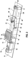
- FIG. 2 12 shows an oblique plan view of the loading device 10 according to the first aspect of the present invention.
- FIG 3 shows a detailed view of the charging head 12 of the charging device 10 according to the first aspect of the present invention.
- a first plurality of first electrical contacts 14 is formed on the first surface 13 of the charging head 12 with the width B and the length L.
- the first contacts 14 are designed as lamellae which are arranged parallel to one another and to the length L of the charging head 12 and are perpendicular to the first surface 13 .
- the charging head 12 is brought up to a connecting device 110 along the second direction R2 parallel to the slats and the length L.
- Some or all of the lamellae of the first contacts 14 can have different lengths. They can also be offset from one another, in part or all, along the second direction R2. As a result, when the charging head 12 is brought up to the connecting device 110 , a time-staggered contacting and/or decontacting of the various first electrical contacts 14 can result. For example, an electrical first contact 14, which is connected to a first control device of the charging device 10, can first be contacted with a second electrical contact of the connection device 110, which is connected to a second control device of the connection device 110. If, for example, one of the control devices sends an abort signal output, about the actuator 16 can be controlled by the first control device to reverse the direction of rotation D.
- the charging device can be designed flexibly for charging with direct current or with alternating current. Information about whether charging is to take place with direct or alternating current or another type of current can be transmitted, for example, when a first contact 14 is contacted for the first time.
- first contacts 14 are formed on the charging head 12, ie the first plurality is five.
- the first plurality can also be, for example, seven or more.
- Five and seven contacts can meet current standards for 1- and 3-phase charging with direct current. The majority can also be an even number and can be four or six, for example.
- One or more of the first contacts 14 can be configured for transmitting data and/or control signals, as a ground line, as a high-voltage line, as a low-voltage line, etc.
- FIG. 1 shows a schematic plan view from below of an electrical connection device 110 of a vehicle for charging a battery of the vehicle according to a first embodiment of the second aspect of the present invention.
- the connection device 110 according to the first embodiment of the second aspect and the charging device 10 according to the first embodiment of the first aspect can together represent an embodiment of the charging system according to the invention.
- the connection device 110 is arranged on the underbody U of the vehicle.
- a plate P of the connecting device 110 is mounted on or around two rods 102 arranged parallel to one another in such a way that it can be displaced along the rods 102 .
- the connecting device 110 is connected to the rest of the vehicle via the rods 102 .
- the rods 102 can be hollow inside. Cables can run within the bars 102 between the vehicle, in particular a battery of the vehicle, and the connection device and electrically couple them to one another.
- the displaceability of the plate P on the rods 102 is reduced by at least one spring 104 arranged parallel to the rods 102 .
- the restoring force means a spring force which counteracts a deflection of the plate P and thus also of the receiving head 112 from their respective rest position.
- a receiving head 112 is formed on plate P of the connecting device 110 , which has a second plurality of second electrical contacts 114 on a second surface 113 of the plate P .
- the second electrical contacts 114 are at least partially electrically connected to the battery of the vehicle via the cables within the bars 102 .
- One or more second contacts 114 can also be connected to a control device of the vehicle, by means of which the charging of the battery can be controlled.
- the second surface 113 faces away from the vehicle.
- the receiving head 112 is surrounded by guide means 118 on the second surface 113 of the plate P, which serves to guide a loading head 12 of a loading device 10 according to the invention to a predetermined loading position with respect to the receiving head 112.
- the guide means 118 can be described in plan as having a "three-tiered symmetrical hourglass shape" with the receiving head 112 at the most recent location at the center of the hourglass.
- the guide device 118 thus forms a channel K which tapers in the direction of the receiving head 112 in a V-shape or funnel-shaped at both ends of the channel until the width of the channel K essentially corresponds to the width of the receiving head 112 .
- the width of the receiving head 112 is essentially equal to the width B of the charging head 12 according to the invention, so that the channel K can be completely traversed by the charging head 12 of the charging device 10 according to the invention.
- the receiving head 112 is formed in a section K ⁇ of the channel K with a constant width.
- the charging head 12 of the charging device 10 will not accurately move toward the receiving head 112 in a desired target direction R2 ⁇ when moving along the second direction R2 pressed against the underbody of the vehicle, as in relation to FIG Figure 1B described.
- the desired direction R2' lies along a longitudinal axis of the channel K, in particular along an axis of symmetry as the longitudinal axis.
- the second direction R2 is fixed by the arms 21 and 23.
- the loading head 12 hits the V-shaped interior of the channel of the guide device 118 during its movement and presses against a channel inner wall 119 in the second direction R2, a force can be exerted in a third or fourth direction R3, R4 perpendicular to the target direction R2 'and parallel to the second surface 113 arise.
- the plate P of the connecting device 110 can be displaced along the rods 102 in the third or fourth direction R3, R4 accordingly, until the loading head 12 enters the section K ⁇ with constant Width of the channel K occurs.
- the charging head 12 is attached to the underbody U of the vehicle, more precisely to the plate P of the connecting device 110 pressed.
- a torque can also be applied - in addition or as an alternative to the above Paragraph described forces - are exerted on the plate P.
- the plate is as in the following Figures 4B and 4C 1, is suspended from the rods 102 by a pivot 132 so that the torque can cause the receiving head 112 to align favorably.
- the desired direction R2 ⁇ defined in relation to the receiving head 112 can be brought into agreement with the second direction R2.
- the springs 104 are tensioned or compressed accordingly. In a rest position, the springs 104 keep the duct K aligned towards the desired direction R2', which is advantageously the forward travel direction of the vehicle.
- Figure 4B 12 shows a schematic plan view from above of the electrical connection device 110 of a vehicle for charging a battery of the vehicle according to the first embodiment of the second aspect of the present invention.
- the panel P is connected to a yoke 130 by a pivot 132 at a back surface 133 of the panel P which is remote from the surface 113 .
- pivot 132 is located over a center of gravity of panel P .
- the two rods 102 are passed through the yoke 130 parallel to one another and parallel to the plate P in such a way that the yoke 130, which is fixedly connected to the plate P, can move along the rods 102. This allows the panel P to slide along the rods 102 as described above.
- the panel P is rotatable by the pivot 132 about a pivot axis perpendicular to the second surface 113 and perpendicular to the rear face 133 of the panel P to facilitate entry of the loading head 12 into the constant-width section K'.
- Figure 4C shows a schematic plan view from the front, in particular from the target direction R2 ⁇ , of an electrical connection device of a vehicle for charging a battery of the vehicle according to the first embodiment of the second aspect of the present invention.
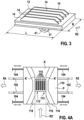
- Figure 5A shows a schematic detailed view from above, ie from the direction of the vehicle, of the receiving head 112 of the connection device 110 according to the first embodiment of the second aspect of the present invention.
- the ten second electrical contacts 114 are parallel to and spaced apart from each other and perpendicular to the second surface 113 .
- the second contacts 114 are each formed as electrically conductive strips within the five guide slots 116 .
- the two second contacts 114 arranged within the same guide slot 116 are each connected to one another via two clip-shaped leaf springs 122, one leaf spring 122 at each of the two longitudinal ends of the two strips.
- the ten leaf springs 122 each exert a spring force urging each strip toward the opposite strip within the same guide slot. A particularly good contact is thus possible if a first contact 14 is inserted between each of the two strips.
- the strips In the longitudinal direction of the second electrical contacts 114, i.e. in particular in a direction along the channel K of the connecting device 110, the strips have edges 117 that are bevelled towards the inside of the respective guide slot 116, so that the first electrical contacts 14 can be inserted even more easily between the two second Contacts 114 in the guide slot 116 can penetrate.
- the first electrical contacts 14 can serve a variety of functions.
- one or more of the second contacts 114 can be configured for transmitting data and/or control signals, as a protective line, as a phase line, as a high-voltage line, as a low-voltage line, etc.
- the second electrical contacts 114 can also be formed within the guide slots 116 as strips of equal length. However, some or all of them can also have different lengths. They may also, with respect to a direction along the guide slots 116, be partially or all offset from each other. As a result, if the first electrical contacts 14 are all designed approximately the same way, it can be achieved that different contacts are made at different times, approximately in the same way as in relation to FIG 3 described.
- At least one of the second electrical contacts 114 is connected directly or indirectly to the battery for charging the battery of the vehicle.
- a charging device can be embodied as part of connecting device 110 of the vehicle, which, via a predetermined one of the second electrical contacts 114, upon contact with a predetermined one of the first electrical contacts 14, by means of the first control device of charging device 10 and/or by means of the second control device of connecting device 110 is controllable.
- the charging of the battery can be controlled by means of the charging device via, for example, two further predetermined second electrical contacts 114 .
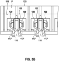
- Figure 5B shows a schematic detailed view from the front of a receiving head of the connection device according to the first embodiment of the second aspect of the present invention.
- edges of the second contacts 114 that are parallel to the plate P and point away from the plate P also have bevels 117' pointing in the direction of the interior of a respective guide slot 116, so that the first electrical contacts 14 even more easily between the two second contacts 114 can penetrate into the guide slot 116.
- FIG. 6 shows a schematic flow diagram of an exemplary method.
- a first method step S01 the lifting device 11 is actuated by means of the actuator 16 in such a way that the loading head 12 connected to the lifting device 11 moves at least partially in the first direction R1 and further in such a way that, if the loading head in the first direction hits a stop surface, the loading head (12) moves in the second direction R2.
- a second method step S01 the charging head 12 moving along the stop surface U, P is guided by the guide device 118 into the predetermined charging position with respect to the receiving head 112 with the second electrical contacts 114.
- a third method step S03 the battery of the vehicle F is charged via the first and second electrical contacts 14, 114 from the energy source.
- FIG. 7 12 shows a charging head 12' of an electric charging device for charging a battery of the vehicle according to a second embodiment of the first aspect of the present invention.
- the charging head 12 'according to the second embodiment is a variant of the charging head 12 according to the first embodiment, wherein on the first surface 13 three first electrical contacts 14-1, 14-2, 14-3, or 14-i , are trained.
- a conductive torus is formed on the first surface 13, which is divided by two electrically insulating insulating blocks 51, 52 into two electrically separate areas, each of which represents a single first contact 14-1, 14-2.
- Another first contact 14-3 is formed as an arch between the insulating blocks 51, 52 and is electrically contacted via connections inside the insulating blocks 51, 52.
- FIG 8 11 shows an electrical connection device 110' of a vehicle for charging a battery of the vehicle according to a second embodiment of the second aspect of the present invention.
- the electrical connection device 110' is designed to accommodate the charging head 12' according to the second embodiment of the first aspect of the present invention and is essentially a variant of the connection device 110.
- the connection device 110' has a guide device 118', the channel K" of which is in the In contrast to the channel K of the guide device 118, it is not V-shaped on both sides, but tapers in a trumpet shape on both sides towards the receiving head 112' of the connecting device 110'.
- the receiving head 112' has three second electrical contacts 114-1, 114-2, 114-3, or 114 for short -i, Two of the second contacts 114-1, 114-2 are formed on inner walls of the channel K" and one directly on the plate P of the terminal device 110' in the middle of the channel K" between the second contacts 114-1, 114-2.
- the contacts 114-1, 114-2, 114-3 are protected by a cover 108 which is slidably suspended on four springs 106.
- connection device 110′ according to the second embodiment of the second aspect and the charging device 10′ according to the second embodiment of the second aspect of the present invention can together represent a second embodiment of the charging system according to the invention.
- the second contact 114-1 contacts the first contact 14-1
- the second contact 114-2 contacts the first contact 14-2
- the second contact 114-3 contacts the first contact 14-3.
- the torus of the loading head 12' is inserted completely into the channel K'' of the guide device 118'.
- the cover 106 is automatically pushed back in the process.
- first and second torsion springs 31, 32 other springs can also be used, such as spiral springs with longitudinal axes perpendicular to the axes of rotation of the first and second pivot joints 41, 42.
- the guide can also be designed with a smooth, lubricated outer surface and the slider can be designed with a smooth inner surface.
- the actuator can be a linear actuator, for example a pneumatic actuator or a magnetic actuator.
- the guide of the loading device can also have a further spring, by which a counter force acts on the slide when it approaches the first bearing block.
- the charging head of the charging device can be protected by a cover which is spring-loaded onto the charging head 12; 12' is suspended.
- the cover can be designed and the springs can be selected in such a way that when the charging head is pressed against the guide device of the connecting device, for example, the cover is automatically pushed back around the first electrical contacts 14; 14-i to release.
- the connection device 110; 110' may be protected by a spring suspended cover which when pressing the loading head 12; 12' is automatically slid back onto the cover to expose the second electrical contacts 114; 114-i to release.
- insides of the covers on the charging head 12; 12' and at the receiving head 112; 112' may be shaped so that the contacts 14, 114; 14-i, 114-i are covered in a form-fitting manner.
- the form-fitting covering can be achieved by a cover which is like a negative for the respective contacts 14, 114; 14-i, 114-i. That is, the first contacts 14; 14-i are covered with a shape similar to the second contacts 114; 114-i is pronounced and vice versa.
- the charger itself can also be placed in a pit or housing which is closed at the top by a drop or sliding door, for example to protect the charger from rain.
- a coarse sensor system can be provided, which determines whether a vehicle to be loaded is located in the predetermined area around the loading device. If this is the case, the drop or sliding door is opened automatically and the actuator of the loading device is then actuated.
Description
Die vorliegende Erfindung betrifft eine elektrische Ladevorrichtung zum Laden einer Batterie eines Fahrzeugs, eine elektrische Anschlussvorrichtung eines Fahrzeugs zum Laden einer Batterie des Fahrzeugs, ein System zum Laden einer Batterie eines Fahrzeugs sowie ein Verfahren zum Laden einer Batterie eines Fahrzeugs.The present invention relates to an electrical charging device for charging a battery of a vehicle, an electrical connection device of a vehicle for charging a battery of the vehicle, a system for charging a battery of a vehicle and a method for charging a battery of a vehicle.
Hybrid- und Elektrofahrzeug greifen zumindest teilweise auf Batterien zurück, um ihren Antriebsstrang mit Energie zu versorgen. ist die Batterie eines Fahrzeugs entleert, kann sie an einer Ladestation mittels einer Ladevorrichtung erneut geladen werden.Hybrid and electric vehicles use batteries, at least in part, to power their powertrain. If the battery of a vehicle is empty, it can be recharged at a charging station using a charging device.
Die möglichst automatische Positionierung des Fahrzeugs bezüglich der Ladevorrichtung und der möglichst automatische Anschluss der Ladevorrichtung an das Fahrzeug zum Laden der Batterie umfassen einige technische Herausforderungen. Automatisierte konduktive Ladesysteme benötigen eine präzise Hinführung eines Ladekopfes, beispielsweise eines Steckers, der Ladevorrichtung an einen Empfangskopf, beispielsweise einer Steckerbuchse, einer Anschlussvorrichtung an einem Fahrzeug.Positioning the vehicle with respect to the charging device as automatically as possible and connecting the charging device to the vehicle for charging the battery as automatically as possible involves some technical challenges. Automated conductive charging systems require a charging head, for example a plug, of the charging device to be guided precisely to a receiving head, for example a socket, of a connection device on a vehicle.
Fahrzeuge weisen häufig aufgrund ihrer unterschiedlichen Designs unterschiedliche Positionen für den Empfangskopf auf. Auch durch eine Anordnung eines Empfangskopf am Unterboden des Fahrzeugs ist keine Einheitlichkeit gewährleistet, da Fahrzeuge unterschiedlich hoch sind und somit der Unterboden von Fahrzeugen unterschiedlich hoch von einer Grundfläche entfernt ist, auf der das Fahrzeug steht. Üblicherweise werden Fahrzeug von ihren Fahrzeugführern nur bis auf einen Fehler von etwa +-10cm präzise und teilweise auch schräg positioniert. Die Aufgabe der Hinführung des Ladekopfs an den Empfangskopf kann beispielsweise von technisch aufwändigen Robotern, etwa mit Zielerfassungs-, Mess- und Bildverarbeitungssystemen, bewältigt werden.Vehicles often have different locations for the receiving head due to their different designs. Uniformity is also not guaranteed by arranging a receiving head on the underbody of the vehicle, since vehicles are of different heights and the underbody of vehicles is therefore at different heights from a base area on which the vehicle is standing. Vehicles are usually only positioned precisely and sometimes at an angle by their vehicle drivers with an error of around +-10cm. The task of guiding the charging head to the receiving head can be managed, for example, by technically complex robots, for example with target detection, measurement and image processing systems.
In der
Die D1 (
Der Stand der Technik nach D2 (
Der Stand der Technik nach D3 (
Der Stand der Technik D4 (
Die vorliegende Erfindung offenbart eine Ladevorrichtung mit den Merkmalen des Patentanspruchs 1.The present invention discloses a loading device having the features of patent claim 1.
Demgemäß ist eine elektrische Ladevorrichtung zum Laden einer Batterie eines Fahrzeugs vorgesehen, mit: einer Hebeeinrichtung, mit welcher ein Ladekopf gekoppelt ist; wobei der Ladekopf an oder auf einer ersten Oberfläche des Ladekopfs eine erste Mehrzahl von ersten elektrischen Kontakten aufweist, welche zum Laden der Batterie zumindest zum Teil mit einer Energiequelle verbindbar sind; einem Aktor, mittels welchem die Hebeeinrichtung derart aktuierbar ist, dass der Ladekopf zumindest teilweise in eine erste Richtung, welche im Wesentlichen senkrecht auf der ersten Oberfläche steht, bewegbar ist; wobei weiterhin die Hebeeinrichtung derart ausgebildet ist, dass der Ladekopf bei einem Stoßen in der ersten Richtung auf eine Anschlagsfläche durch fortgeführtes Aktuieren der Hebeeinrichtung durch den Aktor in eine zweite Richtung entlang der Anschlagsfläche bewegbar ist.Accordingly, there is provided an electric charging device for charging a battery of a vehicle, comprising: a lifting device to which a charging head is coupled; where the Charging head has a first plurality of first electrical contacts on or on a first surface of the charging head, which are at least partially connectable to an energy source for charging the battery; an actuator, by means of which the lifting device can be actuated in such a way that the charging head can be moved at least partially in a first direction, which is essentially perpendicular to the first surface; further wherein the lifting device is configured such that the loading head is movable in a second direction along the abutment surface upon impact in the first direction on an abutment surface by continued actuation of the lifting device by the actuator.
Weiterhin ist als Beispiel, um die Erfindung zu verstehen, eine elektrische Anschlussvorrichtung eines Fahrzeugs zum Laden einer Batterie des Fahrzeugs vorgesehen, mit: einem Empfangskopf, welcher an oder auf einer zweiten Oberfläche der Anschlussvorrichtung eine zweite Mehrzahl von zweiten elektrischen Kontakten aufweist; einer Führungseinrichtung zum Aufnehmen eines an die Anschlussvorrichtung angelegten und sich im Wesentlichen parallel zu der zweiten Oberfläche bewegenden Ladekopfs und zum Führen des sich bewegenden Ladekopfs und des Empfangskopfs in eine vorbestimmte Lagebeziehung zueinander; wobei, falls der Ladekopf und der Empfangskopf sich im Wesentlichen in der vorbestimmten Lagebeziehung zueinander befinden, die Batterie des Fahrzeugs über die zweiten elektrischen Kontakte ladbar ist.Furthermore, by way of example, to understand the invention, there is provided a vehicle electrical connector for charging a battery of the vehicle, comprising: a receiving head having a second plurality of second electrical contacts on or on a second surface of the connector; guide means for receiving a loading head applied to the attachment device and moving substantially parallel to the second surface and for guiding the moving loading head and the receiving head into a predetermined positional relationship to each other; wherein if the charging head and the receiving head are substantially in the predetermined positional relationship to each other, the battery of the vehicle is chargeable via the second electrical contacts.
Weiterhin ist als Beispiel, um die Erfindung zu verstehen, ein Ladesystem zum Laden einer Batterie eines Fahrzeugs vorgesehen mit:
einer außerhalb des Fahrzeugs installierten erfindungsgemäßen elektrischen Ladevorrichtung; und einer an dem Fahrzeug ausgebildeten erfindungsgemäßen elektrischen Anschlussvorrichtung; wobei der Ladekopf der Ladevorrichtung derart ausgebildet ist, dass er in die Führungseinrichtung der Anschlussvorrichtung einführbar ist und zum Laden der Batterie die ersten elektrischen Kontakte an die zweiten elektrischen Kontakte zumindest teilweise anlegbar sind.Furthermore, as an example to understand the invention, a charging system for charging a battery of a vehicle is provided with:
an electric charging device according to the invention installed outside the vehicle; and an electrical connection device according to the invention formed on the vehicle; wherein the charging head of the charging device is designed in such a way that it can be inserted into the guide device of the connection device and the first electrical contacts can be placed at least partially on the second electrical contacts for charging the battery.
Außerdem als Beispiel, um die Erfindung zu verstehen, ein Verfahren zum Laden einer Batterie eines Fahrzeugs vorgesehen mit:
Aktuieren einer Hebeeinrichtung mittels eines Aktors derart, dass ein mit der Hebeeinrichtung verbundener Ladekopf sich zumindest teilweise in eine erste Richtung bewegt, welche im Wesentlichen senkrecht auf einer ersten Oberfläche des Ladekopfs steht, wobei an der ersten Oberfläche eine erste Mehrzahl von ersten elektrischen Kontakten ausgebildet ist, welche zumindest teilweise mit einer Energiequelle verbunden sind; und weiterhin derart, dass, falls der Ladekopf in der ersten Richtung auf eine Anschlagsfläche stößt, sich der Ladekopf in eine zweite Richtung entlang der Anschlagsfläche bewegt; Führen des sich entlang der Anschlagsfläche bewegenden Ladekopfs mittels einer Führungseinrichtung in eine vorbestimmte Ladeposition bezüglich einem Empfangskopf mit zweiten elektrischen Kontakten; und Laden der Batterie des Fahrzeugs über die ersten und zweiten elektrischen Kontakte aus der Energiequelle.Also provided, by way of example in order to understand the invention, is a method for charging a battery of a vehicle comprising:
Actuating a lifting device by means of an actuator such that a charging head connected to the lifting device moves at least partially in a first direction which is substantially perpendicular to a first surface of the charging head, a first plurality of first electrical contacts being formed on the first surface , which are at least partially connected to a power source; and further such that if the loading head encounters an abutment surface in the first direction, the loading head moves in a second direction along the abutment surface; guiding the loading head moving along the abutment surface by means of guide means into a predetermined loading position with respect to a receiving head having second electrical contacts; and charging the battery of the vehicle from the power source via the first and second electrical contacts.
Die der vorliegenden Erfindung zu Grunde liegende Erkenntnis besteht darin, dass mit technisch geringem Aufwand ein System zum Laden einer Batterie eines Fahrzeugs bereitstellbar ist, welches mit einem Aktor, insbesondere mit genau einem einzigen Aktor, derart aktuierbar ist, dass bei einer Position des Fahrzeugs innerhalb eines vorbestimmten Bereichs um eine Ladevorrichtung ein Ladekopf der Ladevorrichtung automatisch zu einem Empfangskopf an dem Fahrzeug hingeführt wird. Das Fahrzeug kann in den vorbestimmten Bereich beispielsweise mittels eines Navigations- oder Parkassistenzsystems geleitet werden.The finding on which the present invention is based is that a system for charging a battery of a vehicle can be provided with little technical effort, which can be actuated with an actuator, in particular with exactly one single actuator, such that when the vehicle is in a position within a predetermined area around a charging device, a charging head of the charging device is automatically guided to a receiving head on the vehicle. The vehicle can be guided into the predetermined area by means of a navigation or parking assistance system, for example.
Der Aktor der erfindungsgemäßen Ladevorrichtung bewirkt, dass der an der Hebeeinrichtung befestigte Ladekopf zunächst an den Unterboden des Fahrzeugs angehoben wird und dann automatisch, an den Unterboden angepresst, an diesem entlang bewegt wird. Die Höhe des Unterbodens des Fahrzeugs muss weder bekannt sein noch muss sie einen bestimmten Wert annehmen. Vielmehr ist die Ladevorrichtung flexibel bei einer Vielzahl von Fahrzeugen ohne jegliche Anpassung einsetzbar. Es kann genügen, wenn die Höhe des Unterbodens Werte in einem bestimmten Wertebereich annimmt.The actuator of the loading device according to the invention has the effect that the loading head attached to the lifting device is first lifted onto the underbody of the vehicle and then automatically, pressed against the underbody, is moved along it. The height of The underbody of the vehicle does not have to be known, nor does it have to assume a specific value. Rather, the charging device can be used flexibly in a large number of vehicles without any adjustment. It may suffice if the height of the underbody assumes values in a specific value range.
Vorteilhafterweise bewirkt ein einzelner Aktor eine lineare Bewegung eines Teils der Hebeeinrichtung, insbesondere eines Gleiters, welche ihrerseits die restliche Bewegung der Ladevorrichtung, wie oben beschrieben, bewirkt. Die Ladevorrichtung ist dadurch technisch besonders einfach, robust und zuverlässig.Advantageously, a single actuator causes a linear movement of a part of the lifting device, in particular a slider, which in turn causes the remaining movement of the loading device as described above. As a result, the charging device is technically particularly simple, robust and reliable.
Das Laden an der Unterseite des Fahrzeugs hat den Vorteil, dass störende Interaktion mit dem Ladesystem bzw. mit der Ladevorrichtung erschwert ist. Weiterhin ist die Designfreiheit der Fahrzeughersteller durch diese Lösung nicht eingeengt.Charging on the underside of the vehicle has the advantage that disruptive interaction with the charging system or with the charging device is made more difficult. Furthermore, the design freedom of the vehicle manufacturer is not restricted by this solution.
Erfindungsgemäß ist an dem Fahrzeug eine Anschlussvorrichtung derart ausgebildet, dass der auf sie auftreffende, sich bewegende Ladekopf auch bei einem gewissen seitlichen Versatz zu der vorbestimmten Ladeposition des Ladekopfs bezüglich des Empfangskopf hingeführt wird. Auf Seiten der Anschlussvorrichtung geschieht dies rein mechanisch ohne elektronische Elemente. Auf Seiten der Ladevorrichtung wird vorzugsweise weiterhin nur der einzige Aktor verwendet.According to the invention, a connection device is designed on the vehicle in such a way that the moving charging head impinging on it is guided to the predetermined charging position of the charging head with respect to the receiving head even if there is a certain lateral offset. On the part of the connection device, this is done purely mechanically without electronic elements. On the charging device side, only the single actuator is preferably used.
Vorteilhafte Ausführungsformen und Weiterbildungen ergeben sich aus den Unteransprüchen sowie aus der Beschreibung unter Bezugnahme auf die Figuren.Advantageous embodiments and developments result from the dependent claims and from the description with reference to the figures.
Gemäß der Erfindung der elektrischen Ladevorrichtung sind die ersten elektrischen Kontakte als zueinander parallele, senkrecht auf der ersten Oberfläche stehende Lamellen ausgebildet. Die ersten Kontakte sind hierdurch besonders stabil mit entsprechenden Kontakten einer Anschlussvorrichtung kontaktierbar.According to the invention of the electrical charging device, the first electrical contacts are designed as lamellae which are parallel to one another and are perpendicular to the first surface. As a result, the first contacts can be contacted in a particularly stable manner with corresponding contacts of a connecting device.
Gemäß einer weiteren bevorzugten Weiterbildung weist zumindest eine der Lamellen eine unterschiedliche Länge im Vergleich zu den restlichen Lamellen auf. Die Kontaktierung kann durch Einschieben der Lamellen in Führungsschlitze mit Kontakten längs der Lamellen erfolgen. Durch die unterschiedliche Länge der zumindest einen Lamelle kann die Kontaktierung dieses ersten Kontakts früher, später, länger oder kürzer erfolgen als die Kontaktierung der restlichen ersten Kontakte.According to a further preferred development, at least one of the lamellae has a different length compared to the remaining lamellae. Contact can be made by pushing the lamellae into guide slots with contacts along the lamellae. Due to the different length of the at least one lamella, this first contact can be contacted earlier, later, longer or shorter than the contacting of the remaining first contacts.
Gemäß einer weiteren bevorzugten Weiterbildung ist zumindest eine der Lamellen in einer Richtung längs der Lamellen versetzt von den restlichen Lamellen angeordnet. Durch die unterschiedliche Länge der zumindest einen Lamelle kann die Kontaktierung dieses ersten Kontakts früher oder später erfolgen als die Kontaktierung der restlichen ersten Kontakte.According to a further preferred development, at least one of the lamellae is offset from the remaining lamellae in a direction along the lamellae. Due to the different length of the at least one lamella, this first contact can be contacted earlier or later than the remaining first contacts.
Gemäß einer weiteren bevorzugten Weiterbildung ist der Ladekopf über einen ersten Arm mit der Hebeeinrichtung gekoppelt; wobei der erste Arm an einem ersten Ende über eine erste Feder mit dem Ladekopf gekoppelt ist; und an einem zweiten Ende über eine zweite Feder mit der restlichen Hebeeinrichtung gekoppelt ist. Hierdurch kann der Ladekopf mittels einer Rückstellkraft an die Anschlagsfläche des Fahrzeugs pressbar und gleichzeitig entlang der Anschlagsfläche bewegbar sein. Gleichzeitig wird vermieden, dass der Ladekopf zu stark an die Anschlagsfläche gepresst werden kann oder dass er aufgrund seines Gewichts nicht an die Anschlagsfläche emporgehoben werden kann.According to a further preferred development, the loading head is coupled to the lifting device via a first arm; wherein the first arm is coupled at a first end to the loading head via a first spring; and coupled at a second end to the remainder of the lifting means via a second spring. As a result, the charging head can be pressed against the stop surface of the vehicle by means of a restoring force and at the same time can be moved along the stop surface. At the same time, it is avoided that the loading head can be pressed too hard against the stop surface or that it cannot be lifted up against the stop surface due to its weight.
Gemäß einer weiteren bevorzugten Weiterbildung sind der Aktor und die Hebeeinrichtung derart ausgebildet, dass die Hebeeinrichtung zum Bewegen des Ladekopfs dadurch aktuierbar ist, dass eine lineare Bewegung eines Gleiters der Hebeeinrichtung durch den Aktor bewirkt wird. Lineare Bewegungen sind besonders einfach und leicht zu kontrollieren. Die dazu benötigten technischen Elemente sind einfach, technisch wenig aufwändig, robust und zuverlässig.According to a further preferred development, the actuator and the lifting device are designed in such a way that the lifting device can be actuated to move the loading head in that a linear movement of a slide of the lifting device is caused by the actuator. Linear movements are particularly simple and easy to control. The technical elements required for this are simple, not technically complex, robust and reliable.
Gemäß einer bevorzugten Weiterbildung der erfindungsgemäßen Anschlussvorrichtung sind die zweiten elektrischen Kontakte parallel zueinander, in einer Richtung parallel zu der zweiten Oberfläche, beabstandet angeordnet. Hierdurch sind Ladeköpfe mit zueinander parallel angeordneten ersten Kontakten für die Kontaktierung der Anschlussvorrichtung verwendbar.According to a preferred development of the connection device according to the invention, the second electrical contacts are arranged parallel to one another, spaced apart in a direction parallel to the second surface. As a result, charging heads with first contacts arranged parallel to one another can be used for contacting the connection device.
Gemäß einer weiteren bevorzugten Weiterbildung ist der Empfangskopf bezüglich des Fahrzeugs bewegbar ausgebildet und über mindestens eine Feder mit dem Fahrzeug verbunden. Die mindestens eine Feder kann eine Rückstellkraft bei Auslenkungen des Empfangskopfs aus einer Ruhelage ausüben. Hierdurch kann die Anschlussvorrichtung automatisch so verschoben werden, dass der Ladekopf und der Empfangskopf in die vorbestimmte Lagebeziehung zueinander bringbar sind, das heißt dass die ersten und zweiten Kontakte einander kontaktieren können.According to a further preferred development, the receiving head is designed to be movable with respect to the vehicle and is connected to the vehicle via at least one spring. The at least one spring can exert a restoring force when the receiving head is deflected from a rest position. As a result, the connecting device can be automatically displaced in such a way that the charging head and the receiving head can be brought into the predetermined positional relationship with one another, that is to say that the first and second contacts can contact one another.
Die obigen Ausgestaltungen und Weiterbildungen lassen sich, sofern sinnvoll, beliebig miteinander kombinieren. Weitere mögliche Ausgestaltungen, Weiterbildungen und Implementierungen der Erfindung umfassen auch nicht explizit genannte Kombinationen von zuvor oder im Folgenden bezüglich der Ausführungsbeispiele beschriebenen Merkmalen der Erfindung. Insbesondere wird dabei der Fachmann auch Einzelaspekte als Verbesserungen oder Ergänzungen zu der jeweiligen Grundform der vorliegenden Erfindung hinzufügen.The above configurations and developments can be combined with one another as desired, insofar as this makes sense. Other possible configurations, developments and implementations of the invention also include combinations of features of the invention described above or below with regard to the exemplary embodiments that are not explicitly mentioned. In particular, the person skilled in the art will also add individual aspects as improvements or additions to the respective basic form of the present invention.
Die vorliegende Erfindung wird nachfolgend anhand der in den schematischen Figuren der Zeichnungen dargestellten Ausführungsbeispiele näher erläutert. Es zeigen:
- Fig. 1A
- eine schematische Seitenansicht einer elektrischen Ladevorrichtung zum Laden einer Batterie eines Fahrzeugs gemäß einer ersten Ausführungsform eines ersten Aspekts der vorliegenden Erfindung in einem ersten Zustand;
- Fig. 1B
- eine schematische Seitenansicht einer elektrischen Ladevorrichtung zum Laden einer Batterie eines Fahrzeugs gemäß der ersten Ausführungsform des ersten Aspekts der vorliegenden Erfindung in einem zweiten Zustand;
- Fig. 2
- zeigt eine schräge Draufsicht auf die Ladevorrichtung gemäß der ersten Ausführungsform des ersten Aspekts der vorliegenden Erfindung;
- Fig. 3
- eine Detailansicht des Ladekopfs der Ladevorrichtung gemäß der ersten Ausführungsform des ersten Aspekts der vorliegenden Erfindung;
- Fig. 4A
- eine schematische Draufsicht von unten auf eine elektrische Anschlussvorrichtung eines Fahrzeugs zum Laden einer Batterie des Fahrzeugs gemäß einer ersten Ausführungsform eines zweiten Aspekts der vorliegenden Erfindung;
- Fig. 4B
- eine schematische Draufsicht von oben auf die elektrische Anschlussvorrichtung eines Fahrzeugs zum Laden einer Batterie des Fahrzeugs gemäß der ersten Ausführungsform des zweiten Aspekts der vorliegenden Erfindung;
- Fig. 4C
- eine schematische Draufsicht von vorne auf eine elektrische Anschlussvorrichtung eines Fahrzeugs zum Laden einer Batterie des Fahrzeugs gemäß der ersten Ausführungsform des zweiten Aspekts der vorliegenden Erfindung;
- Fig. 5A
- eine schematische Detailansicht von oben auf den Empfangskopf der Anschlussvorrichtung gemäß der ersten Ausführungsform des zweiten Aspekts der vorliegenden Erfindung;
- Fig. 5B
- eine schematische Detailansicht von vorne auf den Empfangskopf der Anschlussvorrichtung gemäß der ersten Ausführungsform des zweiten Aspekts der vorliegenden Erfindung;
- Fig. 6
- ein schematisches Flussdiagramm eines erfindungsgemäßen Verfahrens gemäß einem dritten Aspekt der vorliegenden Erfindung;
- Fig. 7
- eine elektrische Ladevorrichtung eines Fahrzeugs zum Laden einer Batterie des Fahrzeugs gemäß einer zweiten Ausführungsform des ersten Aspekts der vorliegenden Erfindung; und
- Fig. 8
- eine elektrische Anschlussvorrichtung eines Fahrzeugs zum Laden einer Batterie des Fahrzeugs gemäß einer zweiten Ausführungsform des zweiten Aspekts der vorliegenden Erfindung.
- Figure 1A
- a schematic side view of an electric charging device for charging a battery of a vehicle according to a first embodiment of a first aspect of the present invention in a first state;
- Figure 1B
- a schematic side view of an electric charging device for charging a battery of a vehicle according to the first embodiment of the first aspect of the present invention in a second state;
- 2
- Fig. 12 shows an oblique plan view of the loading device according to the first embodiment of the first aspect of the present invention;
- 3
- a detailed view of the charging head of the charging device according to the first embodiment of the first aspect of the present invention;
- Figure 4A
- a schematic plan view from below of an electrical connection device of a vehicle for charging a battery of the vehicle according to a first embodiment of a second aspect of the present invention;
- Figure 4B
- a schematic plan view from above of the electrical connection device of a vehicle for charging a battery of the vehicle according to the first embodiment of the second aspect of the present invention;
- Figure 4C
- a schematic plan view from the front of an electrical connection device of a vehicle for charging a battery of the vehicle according to the first embodiment of the second aspect of the present invention;
- Figure 5A
- a schematic detailed view from above of the receiving head of the connection device according to the first embodiment of the second aspect of the present invention;
- Figure 5B
- a schematic detailed view from the front of the receiving head of the connection device according to the first embodiment of the second aspect of the present invention;
- 6
- a schematic flow diagram of an inventive method according to a third aspect of the present invention;
- 7
- a vehicle electric charging device for charging a battery of the vehicle according to a second embodiment of the first aspect of the present invention; and
- 8
- an electrical connection device of a vehicle for charging a battery of the vehicle according to a second embodiment of the second aspect of the present invention.
In allen Figuren sind gleiche bzw. funktionsgleiche Elemente und Vorrichtungen - sofern nichts anderes angegeben ist - mit denselben Bezugszeichen versehen.Identical or functionally identical elements and devices are provided with the same reference symbols in all figures—unless otherwise stated.
Ein Ladekopf 12 weist an einer ersten Oberfläche 13 des Ladekopfs 12 eine erste Mehrzahl von elektrischen Kontakten 14 auf. Die elektrischen Kontakte 14 sind als zueinander parallele, senkrecht auf der ersten Oberfläche 13 stehende Lamellen ausgebildet. Die Lamellen sind, von der Seite her gesehen, trapezförmige Streifen, wobei jeweils die längere der beiden parallelen Seiten der Trapeze mit der ersten Oberfläche 13 verbunden ist. Die Ladevorrichtung 10 ist auf einer Grundfläche G, beispielsweise dem Erdboden, einem Fußboden, einem Fahrzeugboden oder einer sonstigen geeigneten ebenen Fläche, aufgestellt. Vorteilhaft ist ein Anbringen der Ladevorrichtung 10 auf einer im Vergleich zum Erdboden abgesenkten und zu diesem parallelen Fläche oder in einer Versenkung etwa im Boden eines Parkplatzes. Bei einer weiterhin vorteilhaften Ausbildung der Ladevorrichtung 10 in einem Fach oder einer Aushöhlung in einer Bodenwelle kann die Ladevorrichtung 10 beispielsweise vor Regenwasser bei Pfützenbildung geschützt sein. Die erste Oberfläche 13 ist im Wesentlichen parallel zu der Grundfläche G und weist von dieser fort. Bei einer Aufstellung auf dem Erdboden weist die erste Oberfläche 13 also nach oben.A charging
Der Ladekopf 12 ist an eine Hebeeinrichtung 11 gekoppelt, welche mittels eines Aktors 16 aktuierbar ist, um den Ladekopf 12 zu bewegen. Der Ladekopf 12 ist über einen ersten Arm 21 als Teil der Hebeeinrichtung 11 mit der restlichen Hebeeinrichtung 11 drehbar gekoppelt. Der Ladekopf 12 ist über ein erstes Drehgelenk 41 mit einer ersten Torsionsfeder 31 an ein erstes Ende des ersten Arms 21 derart gekoppelt, dass die Achse der ersten Torsionsfeder 31 parallel zu der ersten Oberfläche 13 liegt. Das erste Drehgelenk 41 ist an einer Seitenfläche 15 des Ladekopfs 12 ausgebildet, welche von der ersten Oberfläche 13 abgewandt ist. Mittels der ersten Torsionsfeder 31 ist der Ladekopf 12 um die Achse der ersten Torsionsfeder in einem ersten Winkelbereich kippbar, wobei in der Ruhelage die erste Oberfläche 13 parallel zu der Grundfläche G liegt. Der erste Winkelbereich liegt zwischen -90° und +90°, vorteilhafterweise zwischen -45° und +45°, insbesondere zwischen -30° und +30°. Der erste Arm 21 ist an einem zweiten Ende des ersten Arms 21 mittels einer zweiten Torsionsfeder 32 an einem zweiten Gelenk 42 mit der restlichen Hebeeinrichtung 11 drehbar gekoppelt. Die Drehachse des zweiten Drehgelenks 42 ist parallel zu der Drehachse des ersten Drehgelenks 41.The
Der Aktor 16 ist gemäß der ersten Ausführungsform als Elektromotor zum Drehen einer Welle W ausgebildet. Die Welle W ist schlüssig mit einer Führung 18 der Hebeeinrichtung 11 verbunden, welche als dünner Voll- oder Hohlzylinder mit teilweise einem Schraubengewinde am Außenmantel ausgebildet ist. Auf die Führung 18 ist ein Gleiter 20 der Hebeeinrichtung 11 mittels eines inneren Schraubengewindes montiert, welches in das Schraubengewinde der Führung 18 eingreift.The
An dem Gleiter 20 sind zwei zweite Arme 22 der Hebeeinrichtung 11 an jeweils ersten Enden der zweiten Arme 22 über zwei dritte Drehgelenke 43 drehbar montiert. Die Drehachsen der dritten Drehgelenke 43 sind kollinear und parallel zu den Drehachsen des ersten und zweiten Drehgelenks 41, 42. An jeweils zweiten Enden der zweiten Arme 22 sind die zweiten Arme 22 über mindestens ein viertes Drehgelenk 44 mit einem dritten Arm 23 der Hebeeinrichtung 11 drehbar gekoppelt. Der dritte Arm 23 ist an einem ersten Ende des dritten Arms 23 über das zweite Drehgelenk 42 mit der zweiten Torsionsfeder 32 mit dem ersten Arm 21 drehbar gekoppelt. Das vierte Drehgelenk 44 ist an dem dritten Arm 23 zwischen dem ersten Ende des dritten Arms 23 und einem zweiten Ende des dritten Arms angeordnet. Das vierte Drehgelenk 44 befindet sich vorzugsweise näher an dem ersten Ende des dritten Arms 23 als an dem Mittelpunkt zwischen dem ersten und zweiten Ende des dritten Arms 23 und auch näher an dem ersten Ende als an dem zweiten Ende des dritten Arms 23. Die Drehachse des vierten Drehgelenks 44 ist parallel zu den Drehachsen der ersten, zweiten und dritten Drehgelenke 41, 42, 43.Two
An dem zweiten Ende des dritten Arms 23 ist der dritte Arm 23 mit einem ersten Lagerblock 17 der Hebeeinrichtung 11 über ein fünftes Drehgelenk 45 drehbar gekoppelt. In dem ersten Lagerblock 17 ist drehbar die Führung 18 an einem ersten Ende der Führung 18 gelagert, wobei die Führung an dem gelagerten Abschnitt ihres Außenmantels kein Schraubgewinde aufweist. Der Lagerblock 17 ist fest mit der Grundfläche G verbunden. Die Drehachse des fünften Drehgelenks 45 ist parallel zu den Drehachsen der ersten, zweiten, dritten und vierten Drehgelenke 41, 42, 43, 44. Die Drehachse DA der Führung 18 - und damit gleichzeitig der Winde W - liegt in einer denkbaren Ebene, welche senkrecht auf den Drehachsen aller Drehgelenke 41, 42, 43, 44, 45 liegt.At the second end of the
Durch die Verbindung des Gleiter 20 über das dritte Gelenk 43, den zweiten Arm 22, das vierte Gelenk 44, den dritten Arm 23, das fünfte Gelenk 45 und den Lagerblock 17 ist der Gleiter 20 auch bei einem Drehen D der Welle W und der Führung 18 durch den Aktor 16 nicht an seinem Schraubgewinde um die Führung 18 drehbar, sondern führt bei dem Drehen D stattdessen eine lineare Bewegung LB aus. Die lineare Bewegung LB kann zwischen dem ersten Lagerblock 17 und einem zweiten Lagerblock 19 stattfinden. Der Gleiter 20 kann sich von dem ersten Lagerblock 17 höchstens so weit entfernen, wie es die kombinierte Länge des zweiten und dritten Arms 22, 23 erlauben. An dem zweiten Lagerblock 19 ist die Führung 18 an einem zweiten Ende der Führung 18 drehbar gelagert und mit der Welle W verbunden.By connecting the
Die ersten elektrischen Kontakte 14 sind über mindestens ein Kabel zumindest teilweise mit einer Energiequelle E verbunden. Zumindest einer der ersten elektrischen Kontakte 14 kann auch über ein weiteres Kabel mit einer ersten Steuereinrichtung der Ladevorrichtung 10 verbunden sein. Mittels dieses ersten Kontakts 14 sind somit Steuer- und/oder Datensignale an das zu ladende Fahrzeug übertragbar. Ein oder mehrere der Kabel können im Inneren des als Hohlprofil ausgebildeten ersten Arms 21 sowie im Inneren des als Hohlprofil ausgebildeten dritten Arms 23 verlaufen und über das Innere des Lagerblocks 17 mit der unter der Grundfläche G angeordneten Energiequelle verbunden sein. Ein oder mehrere Kabel können auch außen an den Armen 21 und/oder 23 entlang geführt werden. Das Kabel kann dabei vorteilhafterweise nur an zwei Punkten an den Armen 21, 23 fixiert werden, sodass es locker genug ist, um Beug- und/oder Streckbewegungen der Arme relativ zueinander zuzulassen. Die Energiequelle E kann gleichzeitig die Energie für den Aktor 16, hier einen elektrischen Drehmotor, bereitstellen.The first
In
Da der dritte Arm 23 über die zweite Torsionsfeder 32 an den ersten Arm 21 gekoppelt ist, wird durch das Drehen D weiterhin der erste Arm 21 mit dem Ladekopf 12 bewegt. Die Federhärte der zweiten Torsionsfeder 32 ist dabei in Bezug auf das Gewicht des ersten Arms 21 und des Ladekopfs 12 so eingestellt, dass der erste Arm 21 sich zunächst im Wesentlichen wie eine Verlängerung des dritten Arms 23 mit diesem hebt. Der erste Arm 21 ist länger als der zweite Arm 23 ausgebildet, beispielsweise dreimal so lang. Damit bewegt sich der Ladekopf 12 an dem ersten Ende des ersten Arms 21 aufgrund des Drehens D zunächst auf einer Kreisbahn mit einer kleinen Auslenkung in Bezug auf die Grundfläche, also teilweise, vorzugsweise hauptsächlich in eine erste Richtung R1, welche senkrecht auf der ersten Oberfläche 13 steht. Ist die Grundfläche G der Erdboden, bewegt sich der Ladekopf 12 also hauptsächlich nach oben.Since the
Bei dem erfindungsgemäßen Einsatz der Ladevorrichtung 10 ist oberhalb der Ladevorrichtung 10 ein Fahrzeug F mit einem Unterboden U in zunächst unbekannter Höhe positioniert. Trifft der Ladekopf 12 während seiner Bewegung, wie in Bezug auf
An der ersten Oberfläche 13 des Ladekopfs 12 mit der Breite B und der Länge L ist eine erste Mehrzahl von ersten elektrischen Kontakten 14 ausgebildet. Die ersten Kontakte 14 sind als parallel zueinander und zu der Länge L des Ladekopfs 12 angeordnete Lamellen ausgebildet, welche senkrecht auf der ersten Oberfläche 13 stehen. Erfindungsgemäß wird der Ladekopf 12 entlang der zweiten Richtung R2 parallel zu den Lamellen und der Länge L an eine Anschlussvorrichtung 110 herangeführt.A first plurality of first
Die Lamellen der ersten Kontakte 14 können, zum Teil oder alle, unterschiedlich lang sein. Sie können auch entlang der zweiten Richtung R2, zum Teil oder alle, versetzt voneinander angeordnet sein. Dadurch kann sich bei dem Heranführen des Ladekopfs 12 an die Anschlussvorrichtung 110 eine zeitlich versetzte Kontaktierung und/oder Dekontaktierung der verschiedenen ersten elektrischen Kontakte 14 ergeben. Beispielsweise kann ein elektrischer erster Kontakt 14, welcher mit einer ersten Steuereinrichtung der Ladevorrichtung 10 verbunden ist, zuerst mit einem zweiten elektrischen Kontakt der Anschlussvorrichtung 110 kontaktiert werden, welcher mit einer zweiten Steuereinrichtung der Anschlussvorrichtung 110 verbunden ist. Wird dabei beispielsweise von einer der Steuereinrichtungen ein Abbruchsignal ausgegeben, kann etwa der Aktor 16 von der ersten Steuereinrichtung gesteuert werden, den Drehsinn des Drehens D umzukehren.Some or all of the lamellae of the
Die Ladevorrichtung kann flexibel zum Laden mit Gleichstrom oder mit Wechselstrom ausgebildet sein. Informationen darüber, ob mit Gleich- oder Wechselstrom oder einer sonstigen Art von Strom geladen werden soll, können etwa bei der zeitlich ersten Kontaktierung eines ersten Kontakts 14 übermittelt werden.The charging device can be designed flexibly for charging with direct current or with alternating current. Information about whether charging is to take place with direct or alternating current or another type of current can be transmitted, for example, when a
Gemäß
Die Anschlussvorrichtung 110 ist am Unterboden U des Fahrzeugs angeordnet. Eine Platte P der Anschlussvorrichtung 110 ist derart an oder um zwei parallel zueinander angeordneten Stäben 102 gelagert, dass sie entlang der Stäbe 102 verschiebbar ist. Über die Stäbe 102 ist die Anschlussvorrichtung 110 mit dem restlichen Fahrzeug verbunden. Die Stäbe 102 können innen hohl sein. Kabel können innerhalb der Stäbe 102 zwischen dem Fahrzeug, insbesondere einer Batterie des Fahrzeugs, und der Anschlussvorrichtung verlaufen und diese elektrisch aneinander ankoppeln. Die Verschiebbarkeit der Platte P auf den Stäben 102 wird durch mindestens eine, parallel zu den Stäben 102 angeordnete Feder 104 vermindert. Gemäß
Gemäß der beschriebenen Ausführungsform des zweiten Aspekts ist an Platte P der Anschlussvorrichtung 110 ein Empfangskopf 112 ausgebildet, welcher eine zweite Mehrzahl von zweiten elektrischen Kontakten 114 auf einer zweiten Oberfläche 113 der Platte P aufweist. Über die Kabel innerhalb der Stäbe 102 sind die zweiten elektrischen Kontakte 114 zumindest teilweise mit der Batterie des Fahrzeugs elektrisch verbunden. Ein oder mehrere zweite Kontakte114 können auch mit einer Steuereinrichtung des Fahrzeugs verbunden sein, mittels welcher das Laden der Batterie steuerbar ist.According to the described embodiment of the second aspect, a receiving
Die zweite Oberfläche 113 ist von dem Fahrzeug abgewandt. Der Empfangskopf 112 ist von einer Führungseinrichtung 118 auf der zweiten Oberfläche 113 der Platte P umgeben, welche dazu dient, einen Ladekopf 12 einer erfindungsgemäßen Ladevorrichtung 10 in eine vorbestimmte Ladeposition bezüglich des Empfangskopfs 112 zu führen. Gemäß der in Bezug auf
Üblicherweise wird sich der Ladekopf 12 der Ladevorrichtung 10 nicht genau in einer gewünschten Soll-Richtung R2` auf den Empfangskopf 112 zubewegen, wenn er sich entlang der zweiten Richtung R2 angepresst an den Unterboden des Fahrzeugs bewegt, wie in Bezug auf
Trifft der Ladekopf 12 während seiner Bewegung auf das V-förmige Innere des Kanals der Führungseinrichtung 118 und presst er in der zweiten Richtung R2 gegen eine Kanalinnenwand 119, kann eine Kraft in eine dritte oder vierte Richtung R3, R4 senkrecht zu der Soll-Richtung R2' und parallel zu der zweiten Oberfläche 113 entstehen. Dadurch kann die Platte P der Anschlussvorrichtung 110 entlang der Stäbe 102 entsprechend in die dritte oder vierte Richtung R3, R4 verschoben werden, bis der Ladekopf 12 in den Abschnitt K` mit gleichbleibender Breite des Kanals K eintritt. Daraufhin findet keine Verschiebung in die dritte oder vierte Richtung R3, R4 mehr statt und der Ladekopf 12 trifft genau in einer vorbestimmten Ausrichtung auf den Empfangskopf 112. Der Ladekopf 12 wird erfindungsgemäß an den Unterboden U des Fahrzeugs, genauer an die Platte P der Anschlussvorrichtung 110 gepresst.If the
Trifft der Ladekopf 12 während seiner Bewegung in die zweite Richtung R2 derart auf die Führungseinrichtung 118, dass zwischen der zweiten Richtung R2 und der Soll-Richtung R2' ein nicht-verschwindender Winkel besteht, kann auch ein Drehmoment - zusätzlich oder alternativ zu den im vorangehenden Absatz beschriebenen Kräften - auf die Platte P ausgeübt werden. Die Platte ist, wie in den folgenden
Wie in
In
Gemäß
In longitudinaler Richtung der zweiten elektrischen Kontakte 114, insbesondere also in einer Richtung längs des Kanals K der Anschlussvorrichtung 110, weisen die Streifen zum Inneren des jeweiligen Führungsschlitzes 116 hin abgeschrägte Kanten 117 auf, sodass die ersten elektrischen Kontakte 14 noch leichter zwischen die je zwei zweiten Kontakte 114 in dem Führungsschlitz 116 eindringen können.In the longitudinal direction of the second
Die fünf Führungsschlitze 116, die zehn Blattfedern 122, die zwanzig Schrauben 120 und die zehn zweiten elektrischen Kontakte 114 sind gemäß der vorliegenden Ausführungsform alle gleich ausgebildet. Der Übersichtlichkeit halber wurden daher in
Wie in Bezug auf
Auch die zweiten elektrischen Kontakte 114 können innerhalb der Führungsschlitze 116 als jeweils gleich lange Streifen ausgebildet sein. Sie können aber auch, zum Teil oder alle, unterschiedliche Längen aufweisen. Sie können auch, bezüglich einer Richtung längs der Führungsschlitze 116, zum Teil oder alle voneinander versetzt angeordnet sein. Dadurch sind, falls die ersten elektrischen Kontakte 14 etwa alle gleichartig ausgebildet sind, erreicht werden, dass verschiedene Kontakte zeitlich versetzt hergestellt werden, etwa analog wie in Bezug auf
Zumindest einer der zweiten elektrischen Kontakte 114 ist zum Laden der Batterie des Fahrzeugs mit der Batterie, mittelbar oder unmittelbar verbunden. Es kann als Teil der Anschlussvorrichtung 110 des Fahrzeugs eine Ladevorrichtung ausgebildet sein, welche über einen vorbestimmten der zweiten elektrischen Kontakte 114 bei Kontakt mit einem vorbestimmten der ersten elektrischen Kontakte 14 mittels der ersten Steuereinrichtung der Ladevorrichtung 10 und/oder mittels der zweiten Steuereinrichtung der Anschlussvorrichtung 110 steuerbar ist. Mittels der Ladevorrichtung ist das Laden der Batterie über beispielsweise zwei weitere vorbestimmte zweite elektrische Kontakte 114 steuerbar.At least one of the second
In einem ersten Verfahrensschritt S01 wird die Hebeeinrichtung 11 mittels des Aktors 16 derart aktuiert, dass der mit der Hebeeinrichtung 11 verbundene Ladekopf 12 sich zumindest teilweise in die erste Richtung R1 bewegt und weiterhin derart, dass, falls der Ladekopf in der ersten Richtung auf eine Anschlagsfläche stößt, sich der Ladekopf (12) in die zweite Richtung R2 bewegt.In a first method step S01, the lifting
In einem zweiten Verfahrensschritt S01 wird der sich entlang der Anschlagsfläche U, P bewegende Ladekopfs 12 mittels der Führungseinrichtung 118 in die vorbestimmte Ladeposition bezüglich dem Empfangskopf 112 mit den zweiten elektrischen Kontakten 114 geführt.In a second method step S01, the charging
In einem dritten Verfahrensschritt S03 wird die Batterie des Fahrzeugs F über die ersten und zweiten elektrischen Kontakte 14, 114 aus der Energiequelle geladen.In a third method step S03, the battery of the vehicle F is charged via the first and second
Bei dem Ladekopf 12' gemäß der zweiten Ausführungsform handelt es sich um eine Variante des Ladekopfs 12 gemäß der ersten Ausführungsform, wobei auf der ersten Oberfläche 13 drei erste elektrische Kontakte 14-1, 14-2, 14-3, oder kurz 14-i, ausgebildet sind. Dazu ist auf der ersten Oberfläche 13 ein leitender Torus ausgebildet, welcher durch zwei elektrisch isolierende Isolierblöcke 51, 52 in zwei elektrisch voneinander getrennte Bereiche geteilt wird, von denen jeder einen einzelnen erster Kontakt 14-1, 14-2 darstellt. Zwischen den Isolierblöcken 51, 52 ist ein weiterer erster Kontakt 14-3 als Bogen ausgebildet und über Verbindungen im Inneren der Isolierblöcke 51, 52 elektrisch kontaktiert.The charging head 12 'according to the second embodiment is a variant of the charging
Die elektrische Anschlussvorrichtung 110' ist zur Aufnahme des Ladekopfs 12' gemäß der zweiten Ausführungsform des ersten Aspekts der vorliegenden Erfindung ausgebildet und ist im Wesentlichen eine Variante der Anschlussvorrichtung 110. Die Anschlussvorrichtung 110' weist eine Führungseinrichtung 118' auf, deren Kanal K" sich im Gegensatz zum Kanal K der Führungseinrichtung 118 nicht beidseitig v-förmig, sondern beidseitig trompetenförmig zum Empfangskopf 112' der Anschlussvorrichtung 110' verjüngt. Der Empfangskopf 112' weist drei zweite elektrische Kontakte 114-1, 114-2, 114-3, oder kurz 114-i, auf. Zwei der zweiten Kontakte 114-1, 114-2 sind an Innenwänden des Kanals K" ausgebildet und einer direkt an der Platte P der Anschlussvorrichtung 110' in der Mitte des Kanals K" zwischen den zweiten Kontakten 114-1, 114-2. Die Kontakte 114-1, 114-2, 114-3 sind durch eine Abdeckung 108 geschützt, welche an vier Federn 106 verschiebbar aufgehängt ist.The electrical connection device 110' is designed to accommodate the charging head 12' according to the second embodiment of the first aspect of the present invention and is essentially a variant of the
Die Anschlussvorrichtung 110' gemäß der zweiten Ausführungsform des zweiten Aspekts und die Ladevorrichtung 10' gemäß der zweiten Ausführungsform des zweiten Aspekts der vorliegenden Erfindung können gemeinsam eine zweite Ausführungsform des erfindungsgemäßen Ladesystems darstellen.The
Dabei kontaktiert in der vorbestimmten Ladeposition der zweite Kontakt 114-1 den ersten Kontakt 14-1, der zweite Kontakt 114-2 den ersten Kontakt 14-2 und der zweite Kontakt 114-3 den ersten Kontakt 14-3. Der Torus des Ladekopfs 12' wird dazu vollständig in den Kanal K" der Führungseinrichtung 118' eingeführt. Dabei wird die Abdeckung 106 automatisch zurückgeschoben.In this case, in the predetermined charging position, the second contact 114-1 contacts the first contact 14-1, the second contact 114-2 contacts the first contact 14-2 and the second contact 114-3 contacts the first contact 14-3. For this purpose, the torus of the loading head 12' is inserted completely into the channel K'' of the guide device 118'. The
Obwohl die vorliegende Erfindung anhand bevorzugter Ausführungsbeispiele vorstehend beschrieben wurde, ist sie darauf nicht beschränkt, sondern auf vielfältige Art und Weise modifizierbar. Insbesondere lässt sich die Erfindung in mannigfaltiger Weise verändern oder modifizieren, ohne vom Kern der Erfindung abzuweichen.Although the present invention has been described above on the basis of preferred exemplary embodiments, it is not limited thereto but can be modified in a variety of ways. In particular, the invention can be changed or modified in many ways without departing from the essence of the invention.
Beispielsweise können statt der ersten und zweiten Torsionsfedern 31, 32 auch andere Federn verwendet werden, etwa Spiralfedern mit Längsachsen senkrecht zu den Drehachsen der ersten und zweiten Drehgelenke 41, 42.For example, instead of the first and second torsion springs 31, 32, other springs can also be used, such as spiral springs with longitudinal axes perpendicular to the axes of rotation of the first and second pivot joints 41, 42.
Die Führung kann auch als eine glatte, geschmierte Außenfläche ausgebildet sein und der Gleiter kann mit einer glatten Innenseite ausgebildet sein. Der Aktor kann in diesem Fall ein linearer Aktor sein, beispielsweise ein pneumatischer Aktor oder ein magnetischer Aktor. Die Führung der Ladevorrichtung kann auch eine weitere Feder aufweisen, durch welche eine Gegenkraft auf den Gleiter wirkt, wenn er sich dem ersten Lagerblock nähert.The guide can also be designed with a smooth, lubricated outer surface and the slider can be designed with a smooth inner surface. In this case, the actuator can be a linear actuator, for example a pneumatic actuator or a magnetic actuator. The guide of the loading device can also have a further spring, by which a counter force acts on the slide when it approaches the first bearing block.
Der Ladekopf der Ladevorrichtung kann durch eine Abdeckung geschützt sein, welche mit Federn an dem Ladekopf 12; 12' aufgehängt ist. Die Abdeckung kann so ausgebildet und die Federn können so gewählt sein, dass bei Anpressen des Ladekopfs etwa gegen die Führungseinrichtung der Anschlussvorrichtung die Abdeckung automatisch zurückgeschoben wird um die ersten elektrischen Kontakte 14; 14-i freizugeben. Auch die Anschlussvorrichtung 110; 110' kann durch eine an Federn aufgehängte Abdeckung geschützt sein, welche bei Anpressen des Ladekopfs 12; 12' an die Abdeckung automatisch zurück geschoben wird, um die zweiten elektrischen Kontakte 114; 114-i freizugeben.The charging head of the charging device can be protected by a cover which is spring-loaded onto the charging
Innenseiten der Abdeckungen an dem Ladekopf 12; 12' und an dem Empfangskopf 112; 112' können so geformt sein, dass die Kontakte 14, 114; 14-i, 114-i formschlüssig abgedeckt werden. Dadurch kann eine Ablagerung von kleinen Fremdobjekten an den Kontakten 14, 114; 14-i, 114-i, beispielsweise von Zigarettenstummeln, verhindert werden. Das formschlüssige Abdecken kann durch eine Abdeckung erreicht werden, welche wie ein Negativ zu den jeweiligen Kontakten 14, 114; 14-i, 114-i geformt ist. Das heißt, die ersten Kontakte 14; 14-i werden abgedeckt mit einer Form, welche wie die zweiten Kontakte 114; 114-i ausgeprägt ist und umgekehrt.insides of the covers on the charging
Die Ladevorrichtung kann auch selbst in ein Grube oder einem Gehäuse angeordnet sein, welche bzw. welches nach oben durch eine Fall- oder Schiebetür verschlossen ist, beispielweise um die Ladevorrichtung vor Regen zu schützen. Eine grobe Sensorik kann vorgesehen sein, welche feststellt, ob sich ein zu ladendes Fahrzeug in dem vorbestimmten Bereich um die Ladevorrichtung befindet. Ist dies der Fall, wird automatisch die Fall- oder Schiebetür geöffnet und daraufhin der Aktor der Ladevorrichtung betätigt.The charger itself can also be placed in a pit or housing which is closed at the top by a drop or sliding door, for example to protect the charger from rain. A coarse sensor system can be provided, which determines whether a vehicle to be loaded is located in the predetermined area around the loading device. If this is the case, the drop or sliding door is opened automatically and the actuator of the loading device is then actuated.
Claims (4)
- Electrical charging apparatus (10) for charging a battery of a vehicle, havinga lifting device (11) to which a charging head (12; 12') is coupled;- wherein the lifting device (11) is constructed as follows:- an actuator (16) and a slider (20), wherein the actuator (16) linearly moves the slider (20) on a shaft (18);- a first arm (21), on the end of which the charging head (12) is coupled via a rotary joint (41);- a second arm (22), the first end of which is connected to a rotary joint (43) of the slider (20) via a rotary joint (44) and the second end of which is connected to a third arm (23) via a rotary joint (44);- the first end of the third arm (23) is connected to the first arm (21) via a rotary joint (32), and the second end is connected to a positionally fixed bearing block (17) via a rotary joint (45);- the axes of rotation of the rotary joints (32, 41, 43, 44, 45) are parallel to one another,wherein, on a first surface (13) of the charging head (12; 12'), the charging head (12; 12') has a first plurality of first electrical contacts (14; 14-1; 14-2; 14-3), at least some of which are connectable to an energy source for the purpose of charging the battery; and havingthe actuator (16), by means of which the lifting device (11) is able to be actuated in such a way that the charging head (12; 12') is at least partially movable in a first direction (R1), which is substantially perpendicular to the first surface (13) ;wherein furthermore the lifting device (11) is designed in such a way that, if the charging head (12) comes into contact with a stop surface (U, P), the movement in the original movement direction (R1) is inhibited and, owing to the further movement of the third arm (23), the charging head (12) is moved pressed against the underbody and along a second direction (R2), which is oriented substantially parallel to the first surface (13) and perpendicular to the first direction (R1),whereinthe first plurality of the first electrical contacts (14) are in the form of mutually parallel lamellae which are perpendicular to the first surface (13).
- Electrical charging apparatus (10) according to Claim 1, characterized in that at least one of the lamellae has a different length in comparison with the rest of the lamellae, and/or in that at least one of the lamellae is arranged offset from the rest of the lamellae in a direction (R2) along the lamellae.
- Electrical charging apparatus (10) according to either of Claims 1 and 2, characterized in that the charging head (12) is coupled to the lifting device (11) via a first arm (21); wherein the first arm (21) is coupled at a first end to the charging head (12) via a first spring (31) and is coupled at a second end to the rest of the lifting device (11) via a second spring (32).
- Electrical charging apparatus (10) according to one of preceding Claims 1 to 3, characterized in that the actuator (16) and the lifting device (11) are designed in such a way that the lifting device (11) is able to actuated in that a linear movement (LB) of a slider (20) of the lifting device (11) is effected by the actuator (16).
Applications Claiming Priority (2)
| Application Number | Priority Date | Filing Date | Title |
|---|---|---|---|
| DE102014200290.7A DE102014200290A1 (en) | 2014-01-10 | 2014-01-10 | Electric charging device, electrical connection device, system and method for charging a battery of a vehicle |
| PCT/EP2014/074735 WO2015104080A1 (en) | 2014-01-10 | 2014-11-17 | Electric charging device, electric connection device, system and method for charging a battery of a vehicle |
Publications (2)
| Publication Number | Publication Date |
|---|---|
| EP3092147A1 EP3092147A1 (en) | 2016-11-16 |
| EP3092147B1 true EP3092147B1 (en) | 2023-06-14 |
Family
ID=51903915
Family Applications (1)
| Application Number | Title | Priority Date | Filing Date |
|---|---|---|---|
| EP14799439.6A Active EP3092147B1 (en) | 2014-01-10 | 2014-11-17 | Electric charging device, electric connection device, system and method for charging a vehicle battery |
Country Status (5)
| Country | Link |
|---|---|
| US (1) | US10017062B2 (en) |
| EP (1) | EP3092147B1 (en) |
| CN (1) | CN106061790B (en) |
| DE (1) | DE102014200290A1 (en) |
| WO (1) | WO2015104080A1 (en) |
Families Citing this family (42)
| Publication number | Priority date | Publication date | Assignee | Title |
|---|---|---|---|---|
| US10286793B2 (en) * | 2016-02-05 | 2019-05-14 | Faraday & Future Inc. | Autonomous vehicle charging station connection |
| US10071645B2 (en) | 2016-02-05 | 2018-09-11 | Faraday&Future Inc. | Autonomous vehicle charging station connection |
| US10625611B2 (en) * | 2016-03-03 | 2020-04-21 | Clearpath Robotics Inc. | Electric vehicle charging interface device |
| EP3582992B1 (en) | 2017-02-15 | 2021-02-03 | Volvo Truck Corporation | An arrangement and method for active alignment control of a contact element |
| US9963028B1 (en) * | 2017-02-21 | 2018-05-08 | Ford Global Technologies, Llc | Battery support structure for electrified vehicle |
| BE1025448B1 (en) | 2017-08-01 | 2019-03-04 | Alexander Adrianus Henricus Gerardus Heestermans | System for connecting vehicles to an electric charging station |
| AT520449B1 (en) | 2017-09-27 | 2019-04-15 | Nrg X Charging Systems Gmbh | Component for a charging device and charging device hereby |
| GB2567629B (en) * | 2017-10-13 | 2022-09-21 | Urban Electric Networks Ltd | Retractable charging station |
| EP3552861B1 (en) * | 2018-04-10 | 2023-11-29 | Hager-Electro Sas | Method for positioning an electric vehicle on a charging spot and related charging spot |
| DE102018112494B4 (en) * | 2018-05-24 | 2023-03-16 | Schunk Transit Systems Gmbh | Contact device and rapid charging system |
| NO346644B1 (en) * | 2019-02-19 | 2022-11-14 | Autostore Tech As | A storage system, a container vehicle and a charging station for the storage system and a method of charging the container vehicle. |
| DE102018211507A1 (en) * | 2018-07-11 | 2020-01-16 | Bayerische Motoren Werke Aktiengesellschaft | Charging device for charging a battery of an electrically operated motor vehicle |
| DE102018123350A1 (en) * | 2018-09-21 | 2020-03-26 | Webasto SE | Charging device for charging an electric vehicle |
| US11609350B2 (en) * | 2018-10-12 | 2023-03-21 | Magseis Ff Llc | Modular seismic unit storage system with gantry robot and charging magazine |
| CN109278719A (en) * | 2018-10-18 | 2019-01-29 | 博众精工科技股份有限公司 | A kind of expanding type charging storehouse of automobile electrical changing station |
| CN109278721A (en) * | 2018-10-18 | 2019-01-29 | 博众精工科技股份有限公司 | A kind of lifting connecting mechanism of automobile electrical changing station |
| WO2020089381A1 (en) * | 2018-10-31 | 2020-05-07 | Hirschmann Automotive Gmbh | Device and method for conductive charging |
| US10821847B2 (en) * | 2018-11-06 | 2020-11-03 | Abb Schweiz Ag | Systems and methods for underside charging of electrical vehicles |
| US10951044B2 (en) * | 2018-11-06 | 2021-03-16 | Abb Schweiz Ag | System and method for electrical vehicle charging system |
| US11718194B2 (en) | 2018-11-06 | 2023-08-08 | Jaro Fleet Technologies, Inc. | Charging system for electric vehicles |
| CN109291819A (en) * | 2018-11-07 | 2019-02-01 | 深圳精智机器有限公司 | A kind of vertical charging equipment of new-energy automobile |
| DE202019102347U1 (en) | 2019-04-26 | 2019-05-06 | Igus Gmbh | Device for supplying a consumer |
| US11465517B2 (en) | 2019-05-16 | 2022-10-11 | Abb Schweiz Ag | Electric charging connection for heavy vehicles |
| US11007889B2 (en) * | 2019-08-22 | 2021-05-18 | Ford Global Technologies, Llc | Automatic, hands-free conductive charging system for electric vehicle applications |
| US11014465B2 (en) * | 2019-09-24 | 2021-05-25 | Abb Schweiz Ag | Method and apparatus for automatic charging of electric vehicles |
| DE102019125783A1 (en) | 2019-09-25 | 2019-12-05 | Audi Ag | Energy supply arrangement for supplying a motor vehicle with electrical energy via a conductive plug connection and method for operating a power supply arrangement |
| DE102019125784B4 (en) | 2019-09-25 | 2021-02-11 | Audi Ag | Charging socket for an energy supply arrangement, corresponding energy supply arrangement and method for operating a charging socket |
| DE102019007712A1 (en) * | 2019-11-07 | 2021-05-12 | Kostal Automobil Elektrik Gmbh & Co. Kg | System for conductive charging of a motor vehicle |
| EP3822043B1 (en) | 2019-11-12 | 2023-11-01 | Prodrive Technologies Innovation Services B.V. | Manipulator for handsfree charging electric vehicles |
| DE102019007874A1 (en) | 2019-11-13 | 2020-07-23 | Daimler Ag | Motor vehicle contacting system for transmitting electrical energy for charging a traction battery with an enlarged charging connection external to the vehicle to compensate for an inaccurate positioning of the motor vehicle |
| DE102019132408B4 (en) * | 2019-11-29 | 2021-11-04 | Dr. Ing. H.C. F. Porsche Aktiengesellschaft | Charging interface with an electromagnetically movable cover for electrically charging a traction battery of a motor vehicle and motor vehicle with such a charging interface |
| GB2590980B (en) * | 2020-01-13 | 2022-01-26 | Albright Product Design Ltd | Deployable Electric Vehicle Charging point |
| NL2025529B1 (en) | 2020-05-08 | 2021-11-23 | Prodrive Tech Bv | Manipulator for handsfree charging electric vehicles |
| DE102020116623A1 (en) | 2020-06-24 | 2021-12-30 | Webasto SE | Vehicle unit and ground unit for charging a battery of an electric vehicle |
| CN112117594B (en) * | 2020-09-24 | 2021-03-23 | 如皋市卓凡电子元件有限公司 | New energy automobile charging socket subassembly |
| NL2028211B1 (en) | 2021-05-12 | 2022-11-30 | Prodrive Tech Innovation Services B V | Manipulator for positioning an energy transfer unit for charging a vehicle and charging station for the same |
| CN113479084B (en) * | 2021-05-24 | 2023-09-19 | 国网浙江省电力有限公司嵊泗县供电公司 | Reasonable distribution electric automobile charging field |
| FR3123266A1 (en) * | 2021-05-31 | 2022-12-02 | Electricfil Automotive | Device for electrical connection by magnetic induction and method for electrically recharging a battery of electrical accumulators of a motor vehicle |
| CN113635796B (en) * | 2021-07-28 | 2023-12-15 | 电莫愁科技(北京)有限公司 | Buried lifting structure, charging pile with buried lifting structure and use method |
| WO2023138774A1 (en) * | 2022-01-20 | 2023-07-27 | Schunk Transit Systems Gmbh | Positioning device and fast charging system |
| CN114590151B (en) * | 2022-02-17 | 2023-12-01 | 天达(深圳)新能源科技有限公司 | Just, accomodate charging pile for new energy automobile |
| DE102022104892A1 (en) | 2022-03-02 | 2023-09-07 | Schaeffler Technologies AG & Co. KG | Device for the transmission of electrical power and/or signals between two components mounted so as to be rotatable relative to one another about an axis of rotation |
Citations (14)
| Publication number | Priority date | Publication date | Assignee | Title |
|---|---|---|---|---|
| FR2688350A1 (en) * | 1992-03-09 | 1993-09-10 | Marechal Exploit Procedes | Electrical connection device and, more particularly, a charging (load) connector |
| US5306999A (en) * | 1993-01-15 | 1994-04-26 | Hubbell Incorporated | Electric vehicle charging station |
| US5495159A (en) * | 1993-03-09 | 1996-02-27 | Yugen Kaisha Takuma Seiko | Charging apparatus for driverless transporting vehicle |
| CH688598A5 (en) * | 1993-10-05 | 1997-11-28 | Ernst Erb | Battery recharging and parking bay for electromobile |
| JP2005255144A (en) * | 2004-02-14 | 2005-09-22 | Kazumichi Fujioka | Ground power feeding device |
| DE202009010275U1 (en) * | 2009-03-31 | 2009-10-15 | Baack, Tim | Parking with integrated charging function |
| US20100235006A1 (en) * | 2009-03-12 | 2010-09-16 | Wendell Brown | Method and Apparatus for Automatic Charging of an Electrically Powered Vehicle |
| DE102009015603A1 (en) * | 2009-04-02 | 2010-10-14 | Siemens Aktiengesellschaft | Shore connection for ships with a articulated crane |
| US20110066515A1 (en) * | 2009-09-16 | 2011-03-17 | Horvath Ronald F | Automated electric plug-in station for charging electric and hybrid vehicles |
| US20110181241A1 (en) * | 2010-01-22 | 2011-07-28 | Badger Berkley C | Battery pack charging system with manually maneuvered charge head |
| DE102010028126A1 (en) * | 2010-04-22 | 2011-10-27 | Bfu Ag | Device and method for charging electric buffers in vehicles |
| DE102011082092A1 (en) * | 2011-09-02 | 2013-03-07 | Bayerische Motoren Werke Aktiengesellschaft | Device for the automated production and separation of a charging connection in a plug-in vehicle |
| US20130076902A1 (en) * | 2011-09-26 | 2013-03-28 | Universite Laval | Robotically operated vehicle charging station |
| CN103425073A (en) * | 2013-09-02 | 2013-12-04 | 重庆文理学院 | Automatic telescopic control system of charging plug |
Family Cites Families (14)
| Publication number | Priority date | Publication date | Assignee | Title |
|---|---|---|---|---|
| US5504991A (en) * | 1995-01-19 | 1996-04-09 | Parmley, Sr.; Daniel W. | Apparatus and method for connecting and securing battery packs to battery powered vehicles and/or battery charging devices |
| AU2001287025A1 (en) * | 2000-09-05 | 2002-03-22 | Tara Investments, Llc | System and method for power generation |
| US8307967B2 (en) * | 2007-07-04 | 2012-11-13 | Satyajit Patwardhan | Widely deployable charging system for vehicles |
| DE102009006982A1 (en) | 2008-02-01 | 2009-08-06 | Continental Teves Ag & Co. Ohg | Charging system for charging e.g. battery of hybrid vehicle such as plug-in hybrid vehicle, in garage, has robot unit automatically attaching charging device to interface based on position detected by detector unit |
| US7999506B1 (en) | 2008-04-09 | 2011-08-16 | SeventhDigit Corporation | System to automatically recharge vehicles with batteries |
| EP2564486B1 (en) * | 2010-04-26 | 2020-09-16 | Proterra Inc. | Systems and methods for automatic connection and charging of an electric vehicle at a charging station |
| CN102152746B (en) | 2011-04-21 | 2013-04-10 | 郭仲秋 | Pavement charging and charged device series for electric vehicle |
| TW201249073A (en) * | 2011-05-23 | 2012-12-01 | Shen Yang Technology Entpr Co Ltd | Enclosed energy multi-circulation system and operating method thereof |
| US9770993B2 (en) * | 2013-05-31 | 2017-09-26 | GM Global Technology Operations LLC | Electric vehicle charging station |
| CN103419674A (en) * | 2013-09-02 | 2013-12-04 | 重庆文理学院 | Vertical lifting automatic control instrument for charging arm of electric automobile |
| JP6361329B2 (en) * | 2014-07-04 | 2018-07-25 | 三菱自動車工業株式会社 | Battery pack cable connection structure |
| US9056555B1 (en) * | 2014-10-21 | 2015-06-16 | Wesley Zhou | Vehicle charge robot |
| US9868421B2 (en) * | 2015-06-17 | 2018-01-16 | Ample, Inc. | Robot assisted modular battery interchanging system |
| US9815377B2 (en) * | 2015-07-06 | 2017-11-14 | Hon Hai Precision Industry Co., Ltd. | Battery charging apparatus and method for charging electric vehicle |
-
2014
- 2014-01-10 DE DE102014200290.7A patent/DE102014200290A1/en active Pending
- 2014-11-17 EP EP14799439.6A patent/EP3092147B1/en active Active
- 2014-11-17 CN CN201480077098.9A patent/CN106061790B/en active Active
- 2014-11-17 US US15/110,282 patent/US10017062B2/en active Active
- 2014-11-17 WO PCT/EP2014/074735 patent/WO2015104080A1/en active Application Filing
Patent Citations (14)
| Publication number | Priority date | Publication date | Assignee | Title |
|---|---|---|---|---|
| FR2688350A1 (en) * | 1992-03-09 | 1993-09-10 | Marechal Exploit Procedes | Electrical connection device and, more particularly, a charging (load) connector |
| US5306999A (en) * | 1993-01-15 | 1994-04-26 | Hubbell Incorporated | Electric vehicle charging station |
| US5495159A (en) * | 1993-03-09 | 1996-02-27 | Yugen Kaisha Takuma Seiko | Charging apparatus for driverless transporting vehicle |
| CH688598A5 (en) * | 1993-10-05 | 1997-11-28 | Ernst Erb | Battery recharging and parking bay for electromobile |
| JP2005255144A (en) * | 2004-02-14 | 2005-09-22 | Kazumichi Fujioka | Ground power feeding device |
| US20100235006A1 (en) * | 2009-03-12 | 2010-09-16 | Wendell Brown | Method and Apparatus for Automatic Charging of an Electrically Powered Vehicle |
| DE202009010275U1 (en) * | 2009-03-31 | 2009-10-15 | Baack, Tim | Parking with integrated charging function |
| DE102009015603A1 (en) * | 2009-04-02 | 2010-10-14 | Siemens Aktiengesellschaft | Shore connection for ships with a articulated crane |
| US20110066515A1 (en) * | 2009-09-16 | 2011-03-17 | Horvath Ronald F | Automated electric plug-in station for charging electric and hybrid vehicles |
| US20110181241A1 (en) * | 2010-01-22 | 2011-07-28 | Badger Berkley C | Battery pack charging system with manually maneuvered charge head |
| DE102010028126A1 (en) * | 2010-04-22 | 2011-10-27 | Bfu Ag | Device and method for charging electric buffers in vehicles |
| DE102011082092A1 (en) * | 2011-09-02 | 2013-03-07 | Bayerische Motoren Werke Aktiengesellschaft | Device for the automated production and separation of a charging connection in a plug-in vehicle |
| US20130076902A1 (en) * | 2011-09-26 | 2013-03-28 | Universite Laval | Robotically operated vehicle charging station |
| CN103425073A (en) * | 2013-09-02 | 2013-12-04 | 重庆文理学院 | Automatic telescopic control system of charging plug |
Also Published As
| Publication number | Publication date |
|---|---|
| WO2015104080A1 (en) | 2015-07-16 |
| CN106061790B (en) | 2018-10-23 |
| US10017062B2 (en) | 2018-07-10 |
| CN106061790A (en) | 2016-10-26 |
| EP3092147A1 (en) | 2016-11-16 |
| US20160332525A1 (en) | 2016-11-17 |
| DE102014200290A1 (en) | 2015-07-16 |
Similar Documents
| Publication | Publication Date | Title |
|---|---|---|
| EP3092147B1 (en) | Electric charging device, electric connection device, system and method for charging a vehicle battery | |
| AT520449B1 (en) | Component for a charging device and charging device hereby | |
| EP3347231B1 (en) | Positioning unit for a charging station and contacting method | |
| EP3140151A1 (en) | Vehicle charging station comprising an articulated arm | |
| WO2019166212A1 (en) | Plug-in system for charging an electrical energy store | |
| DE102014226755A1 (en) | Device and method for electrically connecting a charging station with a charging socket of a vehicle | |
| WO2016012172A1 (en) | Vehicle charging station comprising a supply-contact device mounted on an arm | |
| AT516079A1 (en) | Vehicle charging station with a bipartite manipulator | |
| AT520872B1 (en) | pantograph head device | |
| EP3271208B2 (en) | Data transmission device and device for conductive transmission of electrical energy | |
| DE102014213831A1 (en) | Charging device for an electrically rechargeable vehicle | |
| DE102013225196A1 (en) | Device for supplying equipment | |
| WO2020058525A1 (en) | Charging device for charging an electric vehicle | |
| DE102020202537A1 (en) | Charging system and method for charging an electric vehicle | |
| DE102020104832A1 (en) | Charging system, charging device, mobile device and insertion section for a mobile device | |
| DE102012006836A1 (en) | Combined parking and charging device i.e. maneuver multi-story car park, for e.g. small electrical car in urban area, has set of containment assemblies comprising charging units for charging storage unit of vehicles with electrical power | |
| EP4017757A1 (en) | Charging robot and charging apparatus for charging an electrical energy store of a vehicle, and vehicle, the electrical energy store of which can be charged with such a charging apparatus | |
| DE102019130551A1 (en) | Vehicle unit with a charging connection and charging system for charging a battery of an electric vehicle | |
| DE102016115288A1 (en) | Charging station, in particular for a cleaning device | |
| DE3151560A1 (en) | Arrangement for automatically connecting a coupling part assigned to a vehicle and a stationary coupling part for an electrical connecting line, and a plug-in coupling for this | |
| DE102020202533A1 (en) | Charging system and method for autonomous charging of an electric vehicle | |
| DE102019214662A1 (en) | Charging station for an energy storage device on the vehicle | |
| DE102020200292B4 (en) | Device and method for automatically charging an electrically powered motor vehicle | |
| DE202017103306U1 (en) | Charging device for charging an electric vehicle | |
| DE102019007060A1 (en) | Charging device for electrical connection to a charging port of a motor vehicle |
Legal Events
| Date | Code | Title | Description |
|---|---|---|---|
| PUAI | Public reference made under article 153(3) epc to a published international application that has entered the european phase |
Free format text: ORIGINAL CODE: 0009012 |
|
| 17P | Request for examination filed |
Effective date: 20160810 |
|
| AK | Designated contracting states |
Kind code of ref document: A1 Designated state(s): AL AT BE BG CH CY CZ DE DK EE ES FI FR GB GR HR HU IE IS IT LI LT LU LV MC MK MT NL NO PL PT RO RS SE SI SK SM TR |
|
| AX | Request for extension of the european patent |
Extension state: BA ME |
|
| STAA | Information on the status of an ep patent application or granted ep patent |
Free format text: STATUS: REQUEST FOR EXAMINATION WAS MADE |
|
| DAX | Request for extension of the european patent (deleted) | ||
| RAP1 | Party data changed (applicant data changed or rights of an application transferred) |
Owner name: ROBERT BOSCH GMBH |
|
| STAA | Information on the status of an ep patent application or granted ep patent |
Free format text: STATUS: EXAMINATION IS IN PROGRESS |
|
| 17Q | First examination report despatched |
Effective date: 20200703 |
|
| STAA | Information on the status of an ep patent application or granted ep patent |
Free format text: STATUS: EXAMINATION IS IN PROGRESS |
|
| STAA | Information on the status of an ep patent application or granted ep patent |
Free format text: STATUS: EXAMINATION IS IN PROGRESS |
|
| REG | Reference to a national code |
Ref country code: DE Ref legal event code: R079 Ref document number: 502014016611 Country of ref document: DE Free format text: PREVIOUS MAIN CLASS: B60L0011180000 Ipc: B60L0053160000 Ref country code: DE Ref legal event code: R079 Free format text: PREVIOUS MAIN CLASS: B60L0011180000 Ipc: B60L0053160000 |
|
| GRAP | Despatch of communication of intention to grant a patent |
Free format text: ORIGINAL CODE: EPIDOSNIGR1 |
|
| STAA | Information on the status of an ep patent application or granted ep patent |
Free format text: STATUS: GRANT OF PATENT IS INTENDED |
|
| RIC1 | Information provided on ipc code assigned before grant |
Ipc: H01R 13/631 20060101ALI20230228BHEP Ipc: B60L 53/36 20190101ALI20230228BHEP Ipc: B60L 53/35 20190101ALI20230228BHEP Ipc: B60L 53/30 20190101ALI20230228BHEP Ipc: B60L 53/18 20190101ALI20230228BHEP Ipc: B60L 53/16 20190101AFI20230228BHEP |
|
| INTG | Intention to grant announced |
Effective date: 20230328 |
|
| GRAS | Grant fee paid |
Free format text: ORIGINAL CODE: EPIDOSNIGR3 |
|
| GRAA | (expected) grant |
Free format text: ORIGINAL CODE: 0009210 |
|
| STAA | Information on the status of an ep patent application or granted ep patent |
Free format text: STATUS: THE PATENT HAS BEEN GRANTED |
|
| AK | Designated contracting states |
Kind code of ref document: B1 Designated state(s): AL AT BE BG CH CY CZ DE DK EE ES FI FR GB GR HR HU IE IS IT LI LT LU LV MC MK MT NL NO PL PT RO RS SE SI SK SM TR |
|
| REG | Reference to a national code |
Ref country code: CH Ref legal event code: EP |
|
| REG | Reference to a national code |
Ref country code: DE Ref legal event code: R096 Ref document number: 502014016611 Country of ref document: DE |
|
| REG | Reference to a national code |
Ref country code: AT Ref legal event code: REF Ref document number: 1579007 Country of ref document: AT Kind code of ref document: T Effective date: 20230715 |
|
| REG | Reference to a national code |
Ref country code: LT Ref legal event code: MG9D |
|
| REG | Reference to a national code |
Ref country code: NL Ref legal event code: MP Effective date: 20230614 |
|
| PG25 | Lapsed in a contracting state [announced via postgrant information from national office to epo] |
Ref country code: SE Free format text: LAPSE BECAUSE OF FAILURE TO SUBMIT A TRANSLATION OF THE DESCRIPTION OR TO PAY THE FEE WITHIN THE PRESCRIBED TIME-LIMIT Effective date: 20230614 Ref country code: NO Free format text: LAPSE BECAUSE OF FAILURE TO SUBMIT A TRANSLATION OF THE DESCRIPTION OR TO PAY THE FEE WITHIN THE PRESCRIBED TIME-LIMIT Effective date: 20230914 Ref country code: ES Free format text: LAPSE BECAUSE OF FAILURE TO SUBMIT A TRANSLATION OF THE DESCRIPTION OR TO PAY THE FEE WITHIN THE PRESCRIBED TIME-LIMIT Effective date: 20230614 |
|
| PG25 | Lapsed in a contracting state [announced via postgrant information from national office to epo] |
Ref country code: RS Free format text: LAPSE BECAUSE OF FAILURE TO SUBMIT A TRANSLATION OF THE DESCRIPTION OR TO PAY THE FEE WITHIN THE PRESCRIBED TIME-LIMIT Effective date: 20230614 Ref country code: NL Free format text: LAPSE BECAUSE OF FAILURE TO SUBMIT A TRANSLATION OF THE DESCRIPTION OR TO PAY THE FEE WITHIN THE PRESCRIBED TIME-LIMIT Effective date: 20230614 Ref country code: LV Free format text: LAPSE BECAUSE OF FAILURE TO SUBMIT A TRANSLATION OF THE DESCRIPTION OR TO PAY THE FEE WITHIN THE PRESCRIBED TIME-LIMIT Effective date: 20230614 Ref country code: LT Free format text: LAPSE BECAUSE OF FAILURE TO SUBMIT A TRANSLATION OF THE DESCRIPTION OR TO PAY THE FEE WITHIN THE PRESCRIBED TIME-LIMIT Effective date: 20230614 Ref country code: HR Free format text: LAPSE BECAUSE OF FAILURE TO SUBMIT A TRANSLATION OF THE DESCRIPTION OR TO PAY THE FEE WITHIN THE PRESCRIBED TIME-LIMIT Effective date: 20230614 Ref country code: GR Free format text: LAPSE BECAUSE OF FAILURE TO SUBMIT A TRANSLATION OF THE DESCRIPTION OR TO PAY THE FEE WITHIN THE PRESCRIBED TIME-LIMIT Effective date: 20230915 |
|
| PG25 | Lapsed in a contracting state [announced via postgrant information from national office to epo] |
Ref country code: FI Free format text: LAPSE BECAUSE OF FAILURE TO SUBMIT A TRANSLATION OF THE DESCRIPTION OR TO PAY THE FEE WITHIN THE PRESCRIBED TIME-LIMIT Effective date: 20230614 |
|
| PG25 | Lapsed in a contracting state [announced via postgrant information from national office to epo] |
Ref country code: SK Free format text: LAPSE BECAUSE OF FAILURE TO SUBMIT A TRANSLATION OF THE DESCRIPTION OR TO PAY THE FEE WITHIN THE PRESCRIBED TIME-LIMIT Effective date: 20230614 |
|
| PG25 | Lapsed in a contracting state [announced via postgrant information from national office to epo] |
Ref country code: IS Free format text: LAPSE BECAUSE OF FAILURE TO SUBMIT A TRANSLATION OF THE DESCRIPTION OR TO PAY THE FEE WITHIN THE PRESCRIBED TIME-LIMIT Effective date: 20231014 |
|
| PG25 | Lapsed in a contracting state [announced via postgrant information from national office to epo] |
Ref country code: SM Free format text: LAPSE BECAUSE OF FAILURE TO SUBMIT A TRANSLATION OF THE DESCRIPTION OR TO PAY THE FEE WITHIN THE PRESCRIBED TIME-LIMIT Effective date: 20230614 Ref country code: SK Free format text: LAPSE BECAUSE OF FAILURE TO SUBMIT A TRANSLATION OF THE DESCRIPTION OR TO PAY THE FEE WITHIN THE PRESCRIBED TIME-LIMIT Effective date: 20230614 Ref country code: RO Free format text: LAPSE BECAUSE OF FAILURE TO SUBMIT A TRANSLATION OF THE DESCRIPTION OR TO PAY THE FEE WITHIN THE PRESCRIBED TIME-LIMIT Effective date: 20230614 Ref country code: PT Free format text: LAPSE BECAUSE OF FAILURE TO SUBMIT A TRANSLATION OF THE DESCRIPTION OR TO PAY THE FEE WITHIN THE PRESCRIBED TIME-LIMIT Effective date: 20231016 Ref country code: IS Free format text: LAPSE BECAUSE OF FAILURE TO SUBMIT A TRANSLATION OF THE DESCRIPTION OR TO PAY THE FEE WITHIN THE PRESCRIBED TIME-LIMIT Effective date: 20231014 Ref country code: EE Free format text: LAPSE BECAUSE OF FAILURE TO SUBMIT A TRANSLATION OF THE DESCRIPTION OR TO PAY THE FEE WITHIN THE PRESCRIBED TIME-LIMIT Effective date: 20230614 Ref country code: CZ Free format text: LAPSE BECAUSE OF FAILURE TO SUBMIT A TRANSLATION OF THE DESCRIPTION OR TO PAY THE FEE WITHIN THE PRESCRIBED TIME-LIMIT Effective date: 20230614 |
|
| PGFP | Annual fee paid to national office [announced via postgrant information from national office to epo] |
Ref country code: IT Payment date: 20231130 Year of fee payment: 10 Ref country code: FR Payment date: 20231123 Year of fee payment: 10 |
|
| PG25 | Lapsed in a contracting state [announced via postgrant information from national office to epo] |
Ref country code: PL Free format text: LAPSE BECAUSE OF FAILURE TO SUBMIT A TRANSLATION OF THE DESCRIPTION OR TO PAY THE FEE WITHIN THE PRESCRIBED TIME-LIMIT Effective date: 20230614 |